24 minute read
STRUCTURAL SUSTAINABILITY


sustainability and preservation as they pertain to structural engineering
MCEO estimates that $51,000 was saved on superstructure costs by using repurposed steel beams.
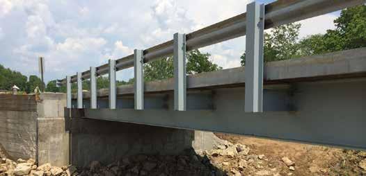
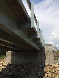
The Green Valley Road Bridge is the fifth structure to be replaced with repurposed steel beams in Muskingum County.
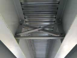
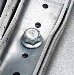
County engineers face a daunting balancing act when it comes to keeping their roads and bridges in service. Today’s transportation needs are much more demanding than what the current Sustainable BridgeBuilding Practices infrastructure can handle. This is especially true when it comes to repairing or replacing bridges. Most of the bridge inventory in state Repurposing Steel to and local jurisdictions is classified as short span, Replace Short Span Bridges less than 140 feet in length. Here’s where the balancing act comes in – on one side of the scale is the safety of the people who travel across the By Douglas R. Davis, P.E., P.S. bridges. On the other side of the scale is a very tight budget that makes it necessary to prioritize which bridges get fixed, and how quickly. Throw into that mix the increased demand for using sustainable products and strict environmental guidelines when federal funding is involved, and the county engineer must make some tough Douglas R. Davis is a County choices. Since safety is always the priority, it Engineer in Muskingum County, takes some creative thinking and innovative Ohio. He can be reached at solutions to meet the ever-increasing public davis.mceo@rrohio.com. demand for efficient roadways. The team at the Muskingum County Engineers Office (MCEO) in Zanesville, Ohio has come up with an effective sustainable solution for building more cost-effective short span bridges. MCEO selects steel for many of its short span bridges and, whenever possible, uses repurposed steel beams removed from bridges taken out of service. The Green Valley Road Bridge near Zanesville is a good example of this plan in action. The original Green Valley Road Bridge, built in 1951, was a 52-foot span painted-steel pony truss with reinforced concrete deck.It was replaced due to its poor condition, a 10-ton load limit, and the need for a structure that would allow crane access to construct a bridge project and a new electric transmission line downstream. The new bridge was fabricated with repurposed W33x141 beams salvaged from a previous bridge replacement in the county. The beams were cut to length, cleaned of previous attachments, and mocked up on skew at the county’s facility. Two rows of bolted diagonal cross-frames were fabricated from angle members that were connected to web stiffeners welded to the beams. Upon completion of fabrication, the structure was disassembled, abrasive-blasted, primed and painted. Completed in 2014, the new Green Valley Road Bridge is 52 feet long and 20 feet wide with five beam lines, four feet on center, covered with a nine-inch-thick composite reinforced concrete deck on a 10-degree skew installed on rehabilitated concrete and masonry abutments. It is the county’s fifth bridge to be replaced with repurposed steel beams. MCEO estimates that $51,000 was saved in superstructure costs by using repurposed beams versus new beams for this project.
Requirements for Repurposing Steel Beams
MCEO chooses repurposed steel when the span length, beam size and hydraulic opening allow. The challenge in using recycled or repurposed beams is finding beams that are long enough and shallow enough to carry the required load for the span. Beam sizing may require several iterations to find the right application and is impacted by
the span, spacing, loading, required vertical clearance, water opening (if over water), beam self-weight, and steel strength. The first step in the selection process is determining if the beam can carry the load. The age and strength of the salvaged beam must be considered when evaluating applications. The age of the steel can provide clues to the steel’s strength; however, lab testing of beam samples should be used if no other information (such as record drawings or invoices) is available. A deeper/taller beam may be required for the same span if a weaker grade of steel is encountered. A few other selection requirements must then be verified, such as if the span is over a road, can traffic pass under the bridge? If the span is over water, can flow resulting from storms clear the bridge without flooding the way?
Saving Costs While Being Sustainable
The beams for the Green Valley Road Bridge were selected from MCEO’s most successful salvage project – the 2005 repurposing of a 326-foot-long, three-beam line, five-span bridge on Pleasant Valley Road. From the Pleasant Valley Road Bridge, MCEO salvaged three W33x130, 33 ksi beams, approximately 48 feet long; and 12 W33X141, 33 ksi beams, approximately 60 feet long. In addition to the Green Valley Road Bridge, these beams were used to construct a 55-foot long x 24-footwide bridge on Rural Dale Road in 2005 and a 38-foot-long x 16-foot-wide bridge on North Branch Road in 2015 – essentially constructing three new bridges from one source. Repurposing can save more than 80 percent of the cost of purchasing new beams while extending the life of a steel beam. At the end of the beam’s extended life, it can be recycled again and again into new steel products. MCEO saved $51,000 with the Green Valley Road Bridge and $40,000 with the North Branch Road Bridge. If not for the salvaged steel, the county would not have been able to replace the North Branch Road Bridge, but instead would have been forced to close it due to its condition and the lack of available funding to purchase new beams.
Availability of Steel Beams
Many large beams can be found on the state and federal systems. MCEO prefers to obtain them before they are cut into short lengths so they can be used for crossings that require deep beam sections. Most salvaged beams can be purchased for scrap steel price. It is ideal if the state has a salvage program because if the
Location Span Beam Size Source
Year Replaced
Cost Savings
1 North Branch Road 38 feet 4-W33x130 Pleasant Valley Road 2015 $40,000 2 Green Valley Road 51 feet 5-W33x141 Pleasant Valley Road 2014 $51,000 3 Rural Dale Road 55 feet 6-W33x141 Pleasant Valley Road 2005 $55,000 4 Richey Road 23 feet 6-W12x79 Stock 2012 $20,000
5 Clay Pike Road 53 feet 4-W30-116 2-W27x102 Stock 2007 $52,000 6 Goosecreek Road 16 feet 5-W14x48 Scrap $0.20/lb 2014 $5,000 7 Bush Hill Road 28 feet 5-W14x48 Scrap $0.20/lb 2014 $7,000
TOTAL SAVINGS $230,000

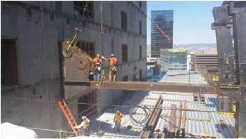
Bridge owners can typically construct short span steel bridges with on-hand tools and equipment using local work crews, saving significant project costs.
beams are taken off of a locally owned bridge that is being replaced with federal dollars and the state does not have a salvage program, then the county must pay for salvaged materials worth more than $5,000 in value. Ohio is considering the development of a salvage program to address this issue. MCEO purchases excess inventoried beams from a local fabricator for reduced costs and rescues beams from the local iron recycling/scrap iron yard. The strong relationships forged over the years with local business owners enables MCEO to purchase beams that are designated as excess stock or slated for recycling. Additionally, MCEO maintains a detailed inventory of existing bridges as part of its repurposing plan. The inventory includes the number, size, length, approximate age and condition of beams available in the yard and throughout the entire existing bridge inventory. MCEO then evaluates the hydraulics for each bridge replacement location to determine the required maximum depth of a repurposed steel beam. When the span length and required vertical clearance under the bridge have been determined, the repurposed beams can be matched for future bridge replacement locations. continued on next page
Recycled steel provides superior durability with minimal impact to the environment.
Steel = Time and Cost Efficiencies in Design and Construction
Approximately 60 percent of Muskingum County’s 409 bridges are constructed with steel. There are 42 steel truss bridges (one built in 1913), three steel girder bridges, 186 steel beam bridges and 19 buried steel structures (corrugated plate/pipe). In addition to its recycling/repurposing advantages, MCEO prefers steel because it provides these cost-saving and time-saving benefits: • Steel is readily available to MCEO as a construction material. • It offers ease of handling, repairability and a uniform fabrication process by
MCEO personnel or a local fabricator. • It is ideal when using local crews.
Many of the bridges in Muskingum
County are over 50 years old. Several of those were built by county crews that set the steel beams with county equipment (no large cranes required, saving significant costs) and repair them with welding or bolting. Many of MCEO’s concrete structures are unrepairable or more costly to repair once they begin to fail due to spalling and reinforcement deterioration. • Steel facilitates ease of load rating. A steel beam bridge can be load rated simply by determining the steel section size and amount of section loss. A concrete structure is more difficult to load rate due to the lack of design drawings showing the amount and location of reinforcement in the structure. • Because of steel’s efficiencies in construction and installation, there is a shorter time required for road closures.
What’s Involved When Using Federal Funding for Local Bridge Projects?
County engineers do not have enough local funds to properly maintain their infrastructure. As a result, they seek federal dollars, which brings with it federal environmental requirements and oversight by the U.S. Fish and Wildlife Service (USFWS), the U.S. Army Corps of Engineers (USACE), and the U.S. Environmental Protection Agency (USEPA). Federally endangered and threatened species (such as bats) limit tree cutting from April through September, which can delay the start of projects. Waterways with over 10 square miles of drainage area may be habitat for freshwater mussels which require, at a minimum, a mussel survey. If mussels are located, then relocation and a check-up to determine their health one year after relocation are required. Small percidae fish (known as darters) spawn in the spring and can delay in-water work until after July 1st. Bald eagle nests can result in restrictions to work around nesting areas and may impact project limits. Work in the waterway falls under the oversight of the U.S. Army Corps of Engineers. Depending on the size, quality and designation as a scenic waterway, permits may need to be obtained to protect water quality and to place fill material in the waterway. The most common USACE permit is required when there is a need for the removal or placement of fill, and is related to section 404 of the Clean Water Act (commonly referred to as a 404 permit). Depending on the length of the waterway to be disturbed, requirements to obtain an individual permit or a general permit will apply. A general permit is straightforward and requires an application and design showing the volume of material to be removed or placed. For a fairly common project requiring only placement of rock channel protection, it can take up to three months to obtain a permit. The application for this permit typically takes 3-6 hours to submit and usually results in a few requests from the USACE for clarification and information before it is issued. An individual permit can take up to a year or more depending on the magnitude of the impact. The Clean Water Act also applies to construction storm water discharges. Projects over one acre in size require a permit and a plan to prevent the release of sediment-laden water from the site. These permits are issued by the state EPA or equivalent. Most bridge projects are located within the flood plain of a waterway and require coordination and a permit for floodplain management under the Federal Emergency Management Agency’s (FEMA) National Flood Insurance Program. The goal of this review is to prevent an increase in the 100-year flood elevation upstream and downstream of the bridge. While securing federal funding is important for rebuilding critical local infrastructure, it can create significant design and construction delays for local jurisdictions.
Training Opportunities and Design Tools Available at No Charge
County engineers are accustomed to meeting challenging demands with creative solutions. Repurposing steel beams is an effective method for MCEO, and Muskingum County will be using repurposed steel well into the future. MCEO has benefited from several helpful training tools for constructing short span steel bridges that are available free of charge from the Short Span Steel Bridge Alliance (SSSBA). These tools include complimentary workshops for county engineers, Departments of Transportation (DOT) personnel, design firms and road supervisors that can be scheduled through each state’s Local Technical Assistance Program/Tribal Technical Assistance Program Centers. Conducted by bridge engineers, the halfday or full-day format covers design tools, case studies, accelerated bridge construction options, practical and cost-effective fabrication, buried steel bridges, recent innovations in protective coatings, and more. Topics can be tailored to the needs and interests of the local agencies. For more information, visit www.shortpsansteelbridges.org. A free web-based design tool developed by the SSSBA provides customized short span steel bridge designs. eSPAN140 delivers preliminary design solutions for individual projects, and the contact information for companies and people who can deliver the bridge. After the user inputs a minimum of three project parameters, a PDF document of steel solutions is delivered within seconds. Since 2012, approximately 2,000 preliminary designs have been generated. More information is available at www.espan140.com. ▪


DON’T BUCKLE
at the Knees
Our new RCKW rigid kneewall connector is a rotational resisting connector that anchors the base of CFS studs to concrete slabs or I-beam flanges. What’s unique about the RCKW clip is its large pre-punched anchor hole that allows ½" diameter concrete screws like our Titen HD® screw anchor. There are also smaller holes to accommodate screw anchorage to structural steel as well as holes that are just the right size for effortless drilling of #12 screws to studs. Used with our heavy 7-gauge RCKWS stiffener, the RCKW connector provides the industry’s highest strength and stiffness values so you won’t ever buckle at the knees. Learn more by calling (800) 999-5099 or visiting our website at strongtie.com/rckw.


Building Blocks
updates and information on structural materials
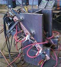
The technological advances in electroslag welding have facilitated its progression from manually fusing vessel joints filled with scrap metal to automatic field-welding of thick steel joints in high rise buildings and long span bridges. The latest version of electroslag welding, ESW-NG (the NG stands for narrow gap – about ¾ inch), is currently accepted by AASHTO for welding common types of bridge steels and is included in the bridge welding code (AWS D1.5: 2010 with interim revisions). This welding method has also satisfied criteria for AISC-defined Demand Critical Welds. A task group is working toward inclusion of ESW-NG welding into the AWS D1.8 Structural Welding Code – Seismic Supplement. An ESW-NG weld consists of coalesced alloycored wire, base metal, and a consumable wire guide. The production of a sound weld requires about one inch of molten slag floating atop a molten weld pool, a motorized flux dispenser, a wire feeder, a water circulator, and a welding power Electroslag Welding: From Shop to Field supply. Either a constant potential DC or a square wave AC welding power supply is well suited for the ESW-NG welding process. Containment of the molten weld and slag pools By Janice J. Chambers, Ph.D., S.E. is provided by a sump, run-off tabs, water-cooled and Brett R. Manning, S.E. copper welding shoes or metal containment plates, and sealant. Welding shoes are detailed for optimal heat transfer and joint orientation. ESW-NG welds are generally single-pass, made in the vertical position, have a deposition rate of about 1 inch per minute, and do not require pre-heat. Defects typically associated with a weld pass, such as slag inclusion and porosity, are very atypical of ESW-NG welds.
Janice J. Chambers is an associate professor of structural engineering at the University of Utah. She may be reached at janice.chambers@utah.edu. Brett R. Manning is a vice president at Schuff Steel. He may be reached at brett.manning@schuff.com.
Process and Development of Electroslag Welding
An initial arc is necessary to commence the ESW welding process. The arc is soon extinguish by predeposited flux. Electric current passing through the slag pool creates a molten resistor that is heated to approximately 3500°F. Hence, ESW is considered to be resistance welding. Advancements made in ESW to achieve the superior physical properties of ESW-NG focused on electrode chemistry, wire guides, flux maintenance, welding shoe architecture, management of heat transfer during the welding process, and automation. ESW Wire Guides and Flux Maintenance During the ESW welding process, wire must be guided into the weld cavity. Consumable metal guides replaced non-consumable guides early in the evolution of ESW. As an ESW weld progresses vertically, a stationary wire guide and the wire it
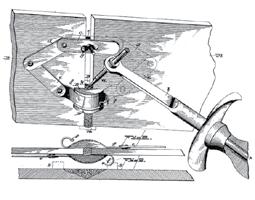
1888 patented welding process resembling electroslag welding used scrap metal as filler material.
is channeling are melted. Metal guides must not make contact with the walls of the joint, which would cause an electric short-circuit. The Linde Division of Union Carbide (Linde) and the Hobart Brothers Company (Hobart) were issued patents that focused on round guide (“guide tube”) profiles. Linde developed a fluxcoated consumable guide tube. The coating insulated the guide from the walls of the joint. Using Linde’s process, the guide tube’s flux liquefaction was unpredictable and the slag pool depth was difficult to manage. A single-wire stationary guide within an ESW weld cavity could create a weld of reasonably uniform properties in joints of up to approximately 2 inches (50 mm) thick. To ensure an even deposition of weld metal across thicker joints, Hobart developed a method of oscillating consumable guides. This method incorporated insulating rings, which prevented electric short-circuiting. An experienced welding operator added flux according to the sounds emitted from the weld pool. Flux


Cross-section of an ESW-NG joint during fabrication and isometric of the contained joint. Box column diaphragm ESW-NG welding.
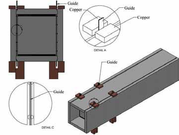
was added when the operator heard the weld excessively arcing. If the weld became too quiet, too much fl ux had been added. Round guides evolved into fl at guides housed with channels for feeding one to multiple wires. Th ese guides eliminated the need for oscillating guides and opened the door for narrowing the welding gap of conventional ESW, from approximately 1.25 inches (32 mm) to ¾ inch (19 mm) used in ESW-NG. Contemporary ESW-NG incorporates automatic wire feeding and fl ux dispensing. Th e wire feed rate is synchronized with guide consumption. About ½ of the required starting fl ux is added to the welding sump before the commencement of welding. Th e balance of the starting fl ux is gradually added during the fi rst minute of welding. As welding progresses vertically, traces of fl ux plate the walls of the welding shoes. Automatic fl ux dispensers maintain a constant-depth slag pool by
ADVERTISEMENT–For Advertiser Information, visit www.STRUCTUREmag.org monitoring variations in electric current and potential. Flux addition is generally very small and constant. Th e required amount of fl ux is about 0.2 ounces (5.5 g) per minute. Welding Shoes and Management of Heat Transfer Side containment has always been used to construct an ESW weld. When possible, ESW-NG welding shoes are constructed of copper, which has very high thermal
TODAY’S STEEL STANDARD
HIGH STRENGTH AND CORROSION RESISTANT REINFORCING STEELS BY MMFX


MMFX Steel offers a family of steel alloys providing high strength (Grades 100 or 120) rebar with varying levels of corrosion resistance under its ChrōmX brand
Solve Rebar Congestion Reduce Placing Time Improve Concrete Placement Lower Cage Weights Lower Rebar Placing Costs Fewer Couplers
Applications Include: High Rise Buildings | Parking Structures | Tunnels | Bridges | Seawalls | Ports
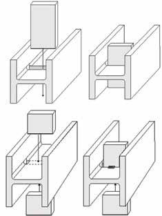
Stiffener plate topology for ESW-NG welding that does not required 180 degree rotation of the girder. Wire guides pass through pre-fabricated slots in web.
conductivity – allowing rapid heat transfer from the base metal. Additional heat retardation is provided by coolant, typically water, that circulates through the channeled body of welding shoes. ESW-NG copper welding shoes are fabricated from solid 1-inch (25 mm) thick copper plate. The finished products are at least 4 inches (100 mm) wide and 12 to 18 inches (300 mm – 450 mm) long. Although rapid heat transfer from the base metal is desirable, if heat escapes from the molten flux and weld pools too rapidly, the weld cross-section will be of exaggerated barrel-shape, or worse, incomplete fusion at the weld corners can occur. The architecture of ESW-NG welding shoes promotes complete and uniform fusion of the weld and base metals across its width. A tri-part welding shoe (Tri-part Shoe) incorporates several features that enable complete fusion at the weld’s corners. A version of the Tri-part Shoe, the Tri-part Articulated (Flex) Shoe, has a flexible enter section that allows the welding shoe to fit snugly against misaligned plates. There are also welding shoes for welding plates of different thickness and a welding shoe for welding T-joints. Welding shoes have also been designed for oblique-angled joints.
Electroslag Welding in the Shop
ESW-NG welds thick plates and cross-sectional elements [from about 1 inch (25 mm) to 6 inches (150 mm) in thickness] much more efficiently than traditional multi-pass arc welding processes such as flux-cored arc welding. However, ESW-NG requires the force of gravity and more instrumentation than conventional arc-welding processes found in the field. Hence, ESW-NG welding has seldom been seen at a construction site, until recently. Shop-Welding of Stiffener, Continuity, and Base Plates The joint formed by a stiffener, continuity, or a base plate and a flange of a wide-flange shape is a T-joint. As welds increase in thickness, so does the expense of typical arc welding processes, because these welds must be made in multiple passes and require preheat. Currently, three stiffener plate configurations are available to ESW-NG welding. The traditional option requires a 180 degree rotation of the girder after completion of welding the first stiffener plate. By fabricating beveled slots entirely or partially through the web of the girder, the need to rotate the girder during stiffener plate welding is eliminated. These slots also have the added advantage of relieving residual stresses existing in rolled shapes near their fillet “k” area. Column stiffener plates were welded with the traditional ESW process in Northern and Southern California buildings prior to 1980. The October 17, 1989 Loma Prieta and January 17, 1994 Northridge earthquakes
Mock-up of instrumented column flange splice. Traditional horizontal FCAW column splices can be rapidly welded at 45 degrees using ESW-NG.
provided real-world comparisons of all of the welding processes used to fabricate steel structures in California. Not one failure or crack propagation was discovered in any of the ESW welds inspected. Box Columns Fabrication The welding of diaphragm plates to the interior walls of box columns using arc welding methods is labor-intensive, particularly welding the final of the four welds needed to attach these plates. With the introduction of ESW’s “key-hole” welding method, this process was made simpler. Holes are cut through two parallel box column plates in line with the centerline of the seam weld gap, where a sump and run-off tabs are installed. A wire guide is inserted to commence the ESW welding process. The vertical rate of rise required to produce a sound keyhole weld is about 1 inch per minute (26 mm/minute). Today, not just the final, but all diaphragm welds of box columns may be quickly made using ESW-NG.
Taking ESW-NG to the Field
Rarely was conventional ESW seen at the site of a major structural engineering project.
engineering manual
STEEL DECK INSTITUTE s ®
DIAPHRAGM DESIGN
EDITION 4
NEW
STEEL DECK INSTITUTE s ®
The Fourth Edition of the SDI Diaphragm Design Manual (DDM04) complies with the requirements of the new ANSI/AISI S310-2013 North American Standard for the Design of Profi led Steel Diaphragm Panels. It includes new and expanded design examples and diaphragm strength tables.
NOW AVAILABLE
One notable ESW field application occurred welding heavy column flange splices of thick plates in a steel fabrication shop. during the construction of the New Orleans, large W-shapes, since joints oriented 45-50 It can economically weld stiffener, conLouisiana Mercedes-Benz Superdome, circa degrees from vertical can be successfully tinuity, and base plates to the flanges of 1975. With the immergence of ESW-NG, welded with ESW-NG. It takes 30 hours or steel shapes, and attach diaphragms to the electroslag welding is now a highly-compet- more to splice a heavy-column using FCAW. inside walls of box columns. Modern techitive option for welding thick steel joints in In comparison, it takes about 30 minutes or nological advances in ESW, embodied in the field. less to weld both flanges of any thickness ESW-NG, has also expanded its role to the East Span, San Francisco – Oakland Bay Bridge Tower The first ESW-NG field-welding occurred material using ESW-NG. Conclusion construction site of a major high-rise building and bridge construction. ESW-NG is proving itself to be the most cost-effective choice at many connections, for the reliable during the construction of the East span of the Electroslag welding may no longer be production of thick welds in steel bridges San Francisco/Oakland Bay Bridge (complete considered as simply one option to splice and buildings.▪ early in 2014), the world’s longest selfanchored suspension (SAS) bridge. The base of its single tower consists of twenty (20), 33-foot (10 m) long ESW-NG welds STRUCTURAL STEEL that join steel plates, up to four inches (100 mm) in thickness. Five uniquely BENDING EXPERTS oriented joints required custom welding -Angle -Flat Bar -Square Bar -Wide Flange -Channel -Square Tubing-Tee -Rectangular Tubing -Round Tube & Pipe -Round Bar -Rail -Plate shoes. Thirty-six-foot (11 m) long guides channeled two 3⁄32-inch (2.4 mm) diameter alloy-cored wires into the molten slag and weld pools as three shoes on each side of the joint were leap-frogged in unison ahead of the pools. The ESW-NG welds were completed in 60 days. Less than 5% of the total length of the welds required repairs. Weld defects were generally due to variations (on the shallow side) in the optimal slag pool depth. The Wilshire Grand Hotel, Los Angeles, California The tallest skyscraper in California, The Wilshire Grand Hotel, is under construction in downtown Los Angeles. Its lateral force resisting system consists of a concrete core, buckling-restrained outrigger braces (BRBs), and perimeter belt trusses. ESW-NG welds joined gusset plates for Lower Outrigger BRBs to the structure. These BRB ESW-NG joints are approximately 12 feet high x 2.75 inches thick (3.6 m x 7 cm). ESW-NG welds up to 49 inches (149 cm) long and 5 inches (15 cm) thick also joined the flanges of the chord and diagonal members of the Lower Belt truss to the face of box columns. This issue contains an article on the Wilshire Grand and two prior issues (December 2014 and August 2015) of STRUCTURE tracked construction of the Wilshire Grand. General Field-welding of Building Structures ESW-NG is poised for common use -Curved Roof Trusses -Canopies -Store Fronts -Spiral Staircases -Modern Art Structures -Pedestrian Bridges -Signage -and MORE! in the field-erection phase of steel con- Located in TOLL-FREE: (866) 252-4628 struction. It is particularly ideal for Tualatin, Oregon WWW.ALBINACO.COM