64 minute read
CODES AND STANDARDS
updates and discussions related to codes and standards This article is the conclusion of a twopart series which discusses special inspection provisions for wood construction found in Chapter 17 of the International Building Code (IBC). Although the IBC is in use or adopted in 50 states, the District of Columbia, Guam, Northern Marianas Islands, New York City, the U.S. Virgin Islands, and Puerto Rico, each state and jurisdiction may not adopt the same edition of the code and/or make amendments to the code. Included are examples of special inspection provisions from California, Washington, and Wisconsin based on the 2012 IBC. The previous article (Part 1, STRUCTURE, January 2016) provided an overview of the special inspection provisions for wood construction found in the 2015 IBC.
State of California
Prior to adopting the IBC as a model code, the 2001 California Building Code (CBC) used the 1997 Uniform Special Inspections for Wood Construction Building Code as a model code. Special inspection for wood construction was only required for prefabricated structural elements and not for seismic and Part 2 wind force resisting systems and components. However, structural observation was required for By David P. Tyree, P.E., C.B.O., James B. Smith, P.E., and Michelle Kam-Biron P.E, S.E. buildings in seismic zones 3 and 4. It wasn’t until the 2007 CBC that California transitioned to the 2006 IBC as the model code. The 2007 CBC was the first edition that included provisions for special inspection of seismic and wind force resisting systems and components. California Agencies, Boards, Commissions and Departments David P. Tyree is the Central Although this article is based on the 2015 IBC, Regional Manager, James B. California has yet to adopt the 2015 IBC as its Smith is the Midwest Regional model code and is in the process of developing Manager, and Michelle Kam- California Amendments, which will eventually Biron is the Director of Education become the 2016 CBC. The CBC is part of at the American Wood Council, the California Code of Regulations, Title 24, also Washington, DC. referred to as the California Building Standards Code, and is published in its entirety every three years by order of the California legislature. The California legislature delegated authority to various state agencies, boards, commissions and departments to create building regulations to implement the state’s statutes. A city, county, or city and county may establish more restrictive building standards reasonably necessary because of local climatic, geological, or topographical conditions. The current 2013 CBC and California Residential Code (CRC) use the 2012 IBC and 2012 International Residential Code (IRC) as its model codes. Chapter 17, Structural Tests and Special Inspections, includes amendments from adopting
Special inspection provisions for construction are found in Chapter 17 of the International Building Code (IBC).
state agencies, including: California Building Standards Commission (State owned buildings, including University and State College buildings and all buildings not otherwise regulated by other state agencies), Department of Housing and Community Development (HCD) 1 & 2 (hotels, motels, apartments, dwellings and permanent buildings within mobile home parks), and Office of Statewide Health Planning and Development (OSHPD) 2 & 3 (skilled nursing facilities & clinics). Chapter 17, Structural Tests and Special Inspections, also includes amendments from adopting state agencies, including: Division of the State Architect-Structural Safety (public schools), Division of the State Architect-Structural Safety/ Community Colleges (community colleges) and OSHPD 1 & 4 (acute-care hospitals and correctional treatment centers). However, there are no significant California Amendments for wood in Chapter 17A. Significant California Amendments to IBC Chapter 17 What follows are several significant amendments to IBC Chapter 17: OSHPD 2: 1704.2.3 Statement of Special Inspection provision requires special inspections for conventional light-frame construction of Section 2308. HCD 1: 1704.2.4 Report requirements references provisions for the construction and inspection of factory-built housing. OSHPD 2: 1705.5.3 Manufactured trusses and assemblies expands the scope of inspection for manufactured trusses and assemblies, and does not limit this to trusses with a clear span greater than or equal to 60 feet. Continuous inspection and a report are required for lumber species, grades, and moisture content; type of glue, temperature, and gluing procedure; type of metal members and metal plate connectors; and workmanship.
City of Los Angeles Th e City of Los Angeles (COLA), Los Angeles Municipal Code (LAMC) Sixth Edition, Chapter IX Building Regulations, Article 1 Buildings, is the Los Angeles Building Code (LABC). Th e LABC adopts by reference portions of the 2013 CBC and 2012 IBC and is amended by Ordinance Number 182850. COLA Special Inspection Signifi cant amendments in the LABC, including 91.1704.2 Special Inspections, require a Registered Deputy Inspector (RDI) rather than just an approved agency as stated in the CBC. In addition, the RDI shall demonstrate competence to the satisfaction of the Superintendent of Building rather than to the building offi cial. Per Division 2 Defi nitions and Abbreviations of the LABC, the Superintendent of Building is the General Manager of the Department of Building and Safety of the City of Los Angeles or a duly authorized representative. COLA has a certifi cation/license requirement for RDIs as required by the Chapter for structural wood. Additional sections provide extensive requirements beyond the ICB or CBC; however, there are no specifi c changes related to the inspection process. Th ere are no LABC amendments to subsection IBC or CBC subsection 1705.5 Wood Construction of Section 1705 Required Verifi cation and Inspection. COLA Structural Observation COLA section 91.1704.5. Structural Observations clarifi es that the registered design professional in responsible charge for the structural design may perform structural observations and he/she may delegate responsibility for structural observations to another registered design professional. Also included are requirements for the owner or owner’s representative to coordinate a preconstruction meeting with the engineer or architect responsible for the structural design, structural observer, contractor, aff ected subcontractors, and deputy inspectors. Th e structural observer is to preside over the meeting. Th e purpose of the meeting is to identify the major structural elements and connections that aff ect the vertical and lateral load systems of the structure, and to review scheduling of the required observations. Th e LABC exempts one-story wood framed Group R-3 and Group U Occupancies less than 2000 square feet in area from structural observation that are not in Risk Category III or IV, provided the adjacent grade is not steeper than 1 unit vertical in 10 units horizontal (10% sloped), and assigned to Seismic Design Category A through D. Th e City of Los Angeles’ website contains an extensive library of Building and Safety Forms such as Registered Deputy Building Inspectors Certificate of Compliance, Structural Observation Report Form, Architects or Engineers Certifi cate of Compliance, Deputy Correction Notice, etc for use, as applicable, by the design professional.
State of Washington
Th e Washington Association of Building Offi cials (WABO) developed a Special Inspection Registration Program to create a uniform method of determining qualifi cations of special inspection agencies and special inspectors. Th e voluntary registration program is designed to provide a means of documenting special inspection and testing qualifi cations, and competency in various types of work cited in the IBC. Th e current list of special inspection categories includes: • Reinforced Concrete (RC) • Prestressed Concrete (PC) • Shotcrete (SC) • Structural Masonry (SM) • Structural Steel and Bolting (SSB) • Structural Welding (SW) • Spray-applied Fire-resistive Materials (FP) • Lateral Wood (LW) • Cold-Formed Steel Framing (CF) • Proprietary Anchors (PA) For the purposes of this article, the focus will be on the Lateral Wood category. Development of the Lateral Wood Special Inspection (LWSI) registration program was initiated by WABO a decade ago. Th e fi rst version employed the special inspection requirements in Chapter 17 of the 2003 IBC. Th is program was a natural addition to WABO’s existing Special Inspection Registration Program (SIRP) which already met other code-mandated needs for special inspections. Since that time, LWSI materials have been updated as new editions of the code are adopted. Washington currently adopts and modifi es the 2012 edition of the IBC. Because critical details in the lateral force resisting framing of wood buildings are beyond the normal scope of conventional framing inspections, this program specifi cally targets critical building components in multi-story wood buildings that must be properly installed to withstand seismic and high-wind events. Th e program aids in increasing the uniformity and quality of inspection procedures, and establishes inspector credentials. Th e developmental committee, consisting of code offi cials, engineers, and architects,
SIGN UP FOR A FREE TRIAL TODAY
TILT-WERKS.COM Tilt-Werks is a Unique & Powerful New Technology
• Developed specifically for the tilt-up industry • Web based — Can be accessed anywhere, anytime Tilt-Werks Automatically Generates:
• Structural design for all walls/panels • Panel design/shop drawings • Panel reinforcing design & placing drawings • Complete panel reinforcing cut list • Material quantities & cost estimates • Dayton Superior product parts list & pricing • Building Information
Models (BIM)
provided tools to assist in the facilitation of the program and to outline the responsibilities of the LWSI inspector. Those responsibilities include: General • Authority to carry out requirements of the enforcing jurisdiction. • Notify the jurisdiction about the type of inspection in accordance with jurisdiction requirements. • Present for continuous inspection during execution of all work for which the special inspector has been engaged. • Verify that the local jurisdiction inspectors have approved the conditions at the site when required. • Submit periodic written and verbal progress reports to the local jurisdiction as required. • Notify the contractor when discrepancies occur. • Notify the building official of uncorrected discrepancies. • Verify that structural plan changes are properly documented, and approved by the enforcing jurisdiction. • Maintain records of work inspected, including discrepancies and actions taken. • Submit final compliance reports. Technical • Identify lateral force resisting systems for conformance, including shear walls, diaphragms, chords, sub-diaphragms, hold-downs, connectors, and drag struts. • Verify placement of plates, shear walls, diaphragms, squash blocks, hold-downs, strapping, beams, and columns. • Verify stud spacing, blocking, panel material and orientation, nail size and spacing, anchor bolt spacing, location, strap-size and location, and use of glue. Material Identification • Verify wood species and grade, dimensions, sheathing material, and engineered lumber applications. • Verify fasteners, including nails, staples, screws, and bolts for size, type, grade, and location. • Verify hardware, including holddowns, straps, ties, rods, nuts, anchors, engineered systems, and prefabricated panel size types and location. Verifying that the hardware specified on the plans has been installed. Reviewing and verifying manufacturer installation procedures. Workmanship • Verify the proper use of materials, including appropriate cutting, notching, nailing, and member alignment. • Verify material condition, including member damage, shipping, handling, weather impacts, and hardware. • Verify any associated testing that should occur including pullout tests for epoxied anchor bolts. • Review plans for associated general requirements and details for foundations, connections, beams and columns, shear walls, and diaphragms. Through this program, local building jurisdictions can easily ascertain and approve credentials of prospective special inspectors. The program also oversees and certifies quality control agencies where inspectors are employed.
State of Wisconsin
Wisconsin has had a state-wide commercial building code since their Safe Place Statutes were first put in place in 1913. The ensuing Wisconsin Commercial Building Code (WCBC) was developed and went into effect in 1914. Although the use of model codes was being considered in the late 1970s, it was not until 1998 that the State of Wisconsin began the rulemaking process that would consider the then proposed I-Codes for adoption as the state-wide WCBC. Early editions of the WCBC aligned the plan review arm of enforcement with a few of the larger cities that had building inspection departments and with the State agency assigned stewardship of the Safe Place Statutes. Inspections were conducted by those larger cities and the State agency staff. State law placed the greatest responsibility for safe places on the owner, and safe construction of those buildings on supervision by architects or engineers. Understanding the limited role that building departments were expected to take in the requirement for providing a safe place, the Administration section of the WCBC included language to reinforce that it is the responsibility of the owner and architect. By 1976, the WCBC added language to clarify the Wisconsin design professional’s responsibility to ensure that all commercial buildings over 50,000 cubic feet total volume were constructed in accordance with the design plans and comply with the WCBC. The WCBC requirements for a supervising professional cover all aspects of the code. Registered architects and professional engineers functioning as supervising professionals can hire specialists to monitor/inspect special aspects of a project that are deemed critical. The WCBC only included specifics associated with pile foundations and protection of adjoining property (underpinning). At the time the model code provisions associated with Special Inspections were being considered in 1999, it was determined that the methodology in place in Wisconsin corresponded to and in some ways exceeded the provisions for Special Inspection that existed in Chapter 17 of the 2000 International Building Code. Accordingly, the entirety of IBC Chapter 17 was removed from state-wide adoption. Shortly after the first adoption, it was recognized that there were many provisions within Chapter 17 that would be advantageous to users of the code while not conflicting with the state’s Supervising Professional methodology. Accordingly, when the 2006 edition of the IBC was adopted in 2008, the important provisions for in-situ load testing and preconstruction load testing were included. Wisconsin currently adopts and modifies the 2009 IBC by only specifying requirements in IBC sections 1711 (Design Strengths of Materials), 1712 (Alternative Test Procedure), 1713 (Test Safe Load), 1714 (In-situ Load Tests), 1715 (Preconstruction Load Tests) and 1716 (Material and Test Standards). The provisions normally associated with special inspections elsewhere in the United States are currently excluded. Even though the original intent was to allow local municipalities the option to adopt the excluded provisions, the changes made within 2013 Act 270 established the WCBC as a uniform code. Accordingly, the administrative rules that create the WCBC will have to be changed in order to use the Special Inspection program outlined in IBC Chapter 17 or allow programs as implemented in the States of California and Washington. The State of Wisconsin is currently in the middle of their process to evaluate the 2015 edition of the IBC for adoption as the statewide uniform commercial building code.
Conclusion
Each state and jurisdiction can make amendments to the code. Chapter 17 of the IBC dealing with special inspections is not immune from this practice. This article provides perspectives from the states of California, Washington, Wisconsin, and the City of Los Angeles regarding special inspection provisions for wood construction. Structural engineers play an important role in the special inspection process, and all owners and design professionals should be aware of the importance of special inspection in providing a safe, code-compliant building.▪
SLIDING ROOF DESIGN
Frida Restaurant in Torrance, California
By Dilip Khatri, Ph.D., S.E.
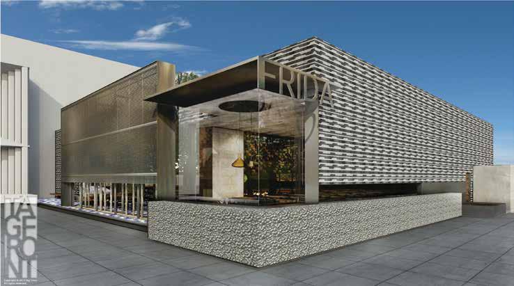
Figure 1. Architectural rendering of front corner elevation of Frida Restaurant.
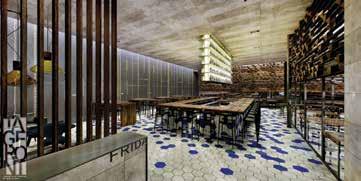
One of the most satisfying aspects of being a structural engineer is to see your project constructed. Even more satisfying is knowing you contributed to making something unique, creative, and aesthetically pleasing to society. Inspiration and gratifi cation are rare in any professional endeavor, and the author is pleased to be part of the team that has made this project a reality. Th e Frida Restaurant defi nitely brings home that feeling of accomplishment, as the Structural Engineer (SE) staff have worked tirelessly with the Architect, Tag Front Design, to meet the design challenges. As this article is written in November 2015, the contractor is completing the fi nal phase of this restaurant for its Grand Opening by December 15, 2015, and by time of publication the restaurant will be serving customers at the Fashion Mall Plaza in Torrance, California. Why is everyone so excited and proud of this retail project? Several reasons come to mind, but one striking feature of this architecturalengineered design is the roof structure. It is designed to “slide open and closed” similar to a convertible rooftop on a car. Figures 1 through 5 provide illustrations on the creative design concept from the Architect. Th e roof has perimeter skylights that allow natural light to illuminate the interior areas to create a warm spatial eff ect, which enhances the dining experience. Perimeter skylights that run the entire length of the roof diaphragm (on both sides) create diaphragm shear transfer issues, which posed structural engineering design challenges. Th e client wanted an interior space that was “free of columns” and had full opening on all sides, with glass and other architectural features. Th is eliminated the possible use of a standard shear wall system. An interior bar design is “suspended” from the ceiling with no visible support from the fl oor (Figure 2). Tag Front designed an open fl oor plan that is free of visible column supports, but follows no standard grid. Specifi cally, the fl oor plan does not follow a standard rectilinear grid system with columns at even spacing. Th e support system is irregular, and with certain columns taking loading with eccentricity/torsional components to the lateral beams.
Structural Design Solutions
Th e selection for the lateral force resisting system (LFRS) was steel moment frames with hollow structural steel tube (HSS) columns and tube beams in both directions, connected with ordinary moment frame connections. Th e HSS columns provided equal moment capacity along both axes, which allowed the design to be balanced effi ciently, due to
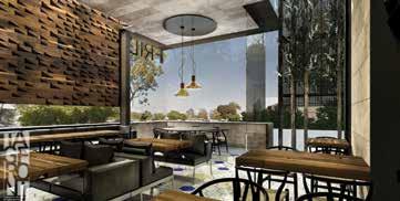
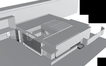
Figure 4. 3D isometric showing sliding roof over garden area.
the irregular grid layout. Certain column locations are positioned with eccentric loading from the roof support and/or beam locations, which required extra design effort to make them work. Foundation design utilized spread footings with base moment connections through a pedestal design interconnected with grade beams. Seismic considerations were important, as the site is classified Seismic Design Category “D”. Fortunately, no liquefaction or unusual soil conditions were present. The sliding roof design created additional dead load demand on the structure, which resulted in 16-inch square HSS sections that carry beam spans of up to 20 feet, in order to meet the Architect/Owner criteria of an open floor plan. The additional dead load also resulted in large footings and grade beams because the base moments were high, due to the large loads (when compared to typical single story retail buildings) and long spans of the supporting beams. Lateral drift was critical in the stiffness design of the LFRS to reduce any possible impact to the adjacent mall structure. On the interior, the open floor design is further enhanced by the unique bar design, which is suspended from the ceiling. This consists of structural tubes welded together and “hangs” from a ceiling beam with no support from the foundation. A lateral analysis of the Bar support structure had to prove that the drift did not exceed certain limits so as to endanger the occupants from flying bottles. Similar to the bar, the fire place is designed within a fully-suspended wall with no direct support from the foundation. A steel support beam with a specially fabricated plate cross section was designed to serve this purpose.
Retractable Roof Design
This project’s most unique feature is the retractable/sliding roof design, which allows the owner to cover the patio seating area, depending on the weather conditions. The sliding roof is elevated approximately four feet above the rest of the roof plane, which creates some challenges for diaphragm shear transfer and produces torsional bending moments on the supporting beams. The roof structure is supported on two rail beams (i.e., two structural tubes) on both sides, which then transfer the load to vertical tube columns resting on the roof diaphragm beams. Seismic loads do not govern, but the wind loads are substantially higher than the dead loads. The analysis encompassed the use of torsional load transfer with vertical tubes to support the sliding roof through an elevated steel moment frame on top of the building moment frame system. Certainly this is one of the most unique designs the author has worked on in recent years. Because of timing issues and tight schedules, the sliding roof has to be installed after the restaurant’s opening date in December 2015 and will be completed in the first quarter of 2016.
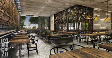
Figure 5. Interior rendering with open space and no column interference.
Tight time frames, short turnarounds, and a critical schedule all characterize the stress level on this project. Structural engineering design is never done in a vacuum, and the SE team collaborated very closely with Tag Front Design and the Contractor to work out the details. During construction there are always change orders, RFIs, and designconstruction issues that must be addressed promptly, sometimes leading to heated “discussions”, but at the end of the day the problems must be solved. The author must admit, even after 33 years in the profession, we are always perpetual students of structural engineering. Every project brings new lessons that hopefully make us sharper engineers for the next project. The Frida project definitely taught new solutions to old problems and reemphasized the team relationship with the Owner, Architect, and Contractor. Perhaps the most important contribution that SEs can make to this working relationship is to be available and open to new ideas. Often, our initial reaction when we see the Architect’s concept is to rethink our proposal! However, a project like this is too delicious of a challenge. Be grateful for the experience. The author discovered that collaboration is not just about being a good engineer, but being open to other people’s ideas and suggestions.▪
Dilip Khatri, Ph.D., S.E., is the Principal of Khatri International Inc. and Khatri Construction Company located in Pasadena, California. He has served as an expert witness for several construction-law firms and as an insurance/forensic investigator of structural failures. He serves as a member of STRUCTURE’s Editorial Board and may be reached at dkhatri@aol.com.
All photos courtesy of Tag Front Design.
Project Team
Structural Engineer: Khatri International Inc., Pasadena, CA Owner: Frida Restaurant, Beverly Hills, CA Architect: Tag Front Design, West Hollywood, CA Contractor: Ck2d Construction Roof Manufacturer: Rollamatic Roofs, Inc. Roof Structural Design: Ficcadenti, Waggoner, & Castle
CROWNING ACHIEVEMENT
By Gerard M. Nieblas, S.E., LEED AP, Peter J. Maranian, S.E. and Jeff Lubberts, P.E.
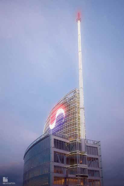
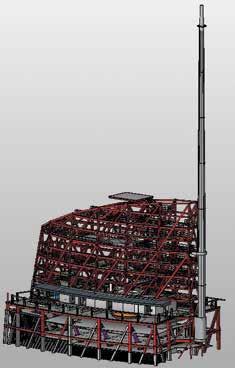
The crowning achievement on the Wilshire Grand project will be the Crown Sail and Spire that set atop the roof of the building. By any measure the crown sail and spire are a building unto themselves. Typically, engineers place structures over rigid bases that are 10x stiffer than the structure above. This allows the structure to be designed as if on a rigid base. With the Wilshire Grand project, engineers set a stiff structure on top of a flexible one. This resulted in a sail and spire with very high seismic design requirements from upper mode effects produced by the supporting 73-story building.
Project Description
The Wilshire Grand Project is approximately 2,000,000 square feet with 900 hotel rooms, 400,000 square feet of office space and 45,000 square feet of retail space. The 5 level subterranean parking covers the entire site and will accommodate 1,100 vehicles. The structure will have a rooftop pool with ocean views, pressurized double decker elevators, an architectural roof top sail and a 300-foot tall architectural spire. The Tower structure is 73 stories, with the lower floors comprised of office space and the upper 40 floors as hotel rooms. The lateral system for the building is a concrete core wall with concrete-filled steel box columns and structural steel framing outside the footprint of the core. The lateral system of the Tower is extremely slender. In the transverse building direction the core wall is 30 feet wide and nearly 1,000 feet tall. Along the height of the structure there are buckling restrained braced frames to reduce the overturning demands of the core wall on the mat foundation, and to stiffen the structure for transverse wind and seismic drift.
Sail Structural System
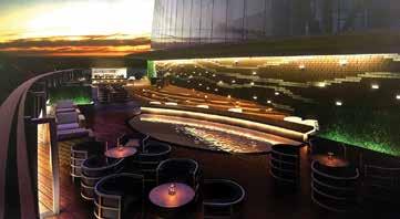
The base of the sail is founded on the 73rd floor with the sky bar and reflective pool. The sail houses the uppermost elevators and elevator machine room along with the tactical approach, building maintenance unit (BMU) #1 on the 75th level, BMU #2 on the 76th level, and catwalks for access to LED lighting.
Sail and Spire with KAL logo. Courtesy of AC Martin.
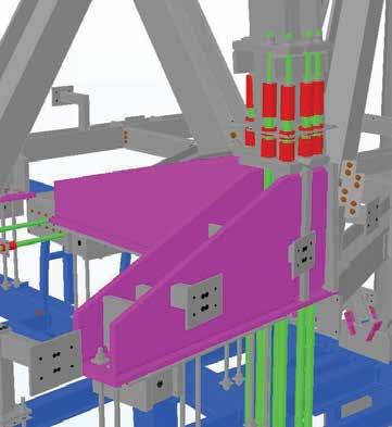
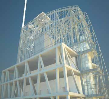
Artist rendering of Sail and Spire. Courtesy of AC Martin. Top connection of spire to sail. Courtesy of Schuff Steel.
The structural system for the sail is a three dimensional space truss. The sail is approximately 100 feet tall and has a structural steel weight of about 900 tons, with a plan area of about 5,000 square feet. The lateral forces from the Maximum Considered Earthquake (MCE) are 4.25G in the North-South direction and 5G in the east-west direction. These seismic forces induce uplifts on the wide flange columns as much as 3,800 kips. These high seismic demands are a result of higher mode effects from the supporting tower. These column bases were anchored with what are normally used as rock anchors (DYWIDAGs). These columns have 8 (150ksi), 2½-inch (2.8-inch OD) anchors embedded into the concrete 14 feet. One of the many design challenges for the support of the sail were the effects of long term creep and shrinkage of the concrete core wall. Portions of the sail are supported directly off the concrete core wall and the edges of the sail extend over the structural steel framing. Over the next 100 years, the concrete core wall will creep and shrink approximately 2 inches more than the elastic shortening of the steel columns. The sail columns at the edges of the steel framing are designed with a 5-inch gap between the bottom of the column and the floor (that would normally support the column). This gap is necessary to keep these columns from pushing down on the steel framing from concrete creep, concrete shrinkage and MCE deflections.
Spire
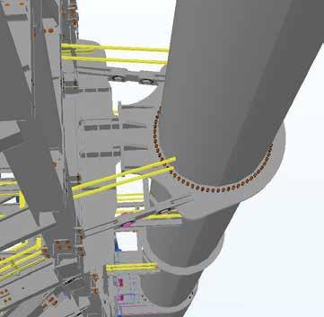
of the spire is a light beacon. It is a tapered stainless steel circular section with perforated holes. Long term creep and shrinkage of the concrete core wall created support problems for the spire. The lateral restraint of the spire on the 75th level has large steel pins with hinges to allow the sail structure to move downward with creep and shrinkage from the supporting core wall below. From transverse MCE loads, the maximum horizontal reaction is 660 kips per pin. All of the vertical loads of the spire are supported on the 73rd level. The spire will be erected in 40 sections and bolted together. The bottom sections of the spire are joined together with 144 11/8-inch A490 bolts. The spire will be subject to wind loading over many, many years. To compensate for fatigue over the life of the structure, wind stresses were limited to 10ksi for the 50 year wind event. Ancillary welds to the spire for ladders and maintenance were also prohibited to prevent any adverse effects from welding. All ancillary attachments to the spire will be in drilled and tapped holes with rounded edges. The rounded edges reduce stress concentrations and allow for a more uniform layer of galvanization. After galvanization, the welds will be peened to relieve residual tensile stresses. The process of peening induces residual compressive stresses in the peened surface. These surface compressive stresses provide better resistance to metal fatigue and to corrosion.
The total height of the spire is 300 feet. The spire is supported vertically off the 72nd floor and is restrained horizontally from wind and seismic forces at the 75th level in the sail. The spire cantilevers 217 feet, with an 83-foot backspan. The spire tapers along its height. At the base, the spire is 6½ feet in diameter and 3.33 feet in diameter at the top. The uppermost 17 feet
BMU’s
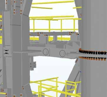
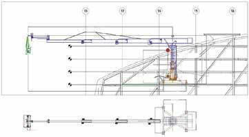
There are two building maintenance units housed in the sail. BMU #1 is on the 75th level and BMU #2 is on the 76th level. Each of these BMUs fold outward and telescope upward to clear the sail and maintain the exterior of the structure below. continued on next page
Hinged connection of spire to sail. Courtesy of Schuff Steel. Plan views of BMUs. Courtesy of Skyrider/GinD.
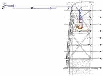
Section of BMU. Courtesy of Skyrider/GinD.
Plan at BMU. Courtesy of Skyrider/GinD.
BMU extended at Tower. Courtesy of Skyrider/GinD.
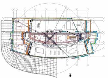
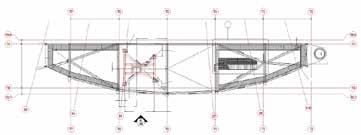
The building maintenance units for the structure are massive. Their dead weights are approximately 128,000 pounds each. When considering the earthquake response of the BMUs on the sail, they place a 6G demand (700 kip singular reaction) on the sail from 1.5MCE. The BMU arms extend approximately 100 feet to reach the longitudinal edges of the structure. These BMUs need to accommodate a sloping curtainwall. On the north face of the structure, the building skin (and structural columns) slopes 6 feet horizontally in three floors. On the west face of the structure, the building slopes over 45 feet horizontally along its height. On the east face, the upper portions of the structure extend out past the lower cantilevered portions below. The BMUs have to, in effect, reach under an overhang.
Conclusion
The Crown Sail and Spire will be the crowning achievement of the Wilshire Grand Project. This will be the tallest building west of the Mississippi. Outside of New York and Chicago, it will be the tallest building in the United States. This building will redefine the skyline of Los Angeles. With its elegant sail atop the structure, it will be the only building in Los Angeles without a flat top roof.▪ Gerard M. Nieblas, S.E., LEED AP, is President of Brandow & Johnston Inc. Peter J. Maranian, S.E., is a Principal and Jeff Lubberts, P.E., is a Project Manager at Brandow & Johnston. Gerard may be reached at gnieblas@bjsce.com.
Project Team
Structural Engineers of Record: Brandow & Johnston Inc. Owner: Hanjin Group Architect: AC Martin Inc. General Contractor: Turner Construction
Structural Consultant for Performance Based Design:
Thornton Tomasetti
Marriott Marquis Renovation
By Virginia Mosquera, Ph.D., P.E.
Supporting world’s largest LED billboard installation at the crossroads of the world required quick coordination and immediate solutions to confl icts.
The iconic Marriott Marquis hotel, located at the center of Times Square, was recently renovated to display the world’s largest high-defi nition LED billboard (Figure 1). At fi ve stories tall, this gigantic screen spans the entire width of the building (a full city block, from West 45th Street to West 46th Street on Broadway), wrapping partway around its sides. Th e renovation also included converting the two underground parking levels and fi rst two above grade-levels to prime double-height retail spaces, the remodeling of back-of-theater rooms, and the creation of new rooftop space off ering coveted views of the New Year’s Eve ball dropping.
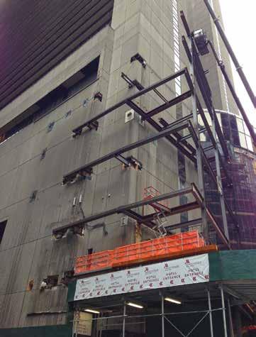
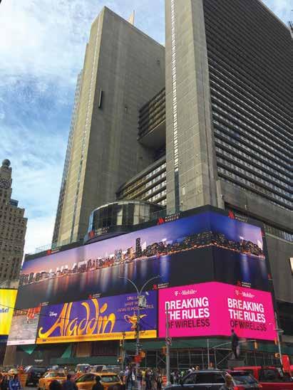
Figure 1. Marriott Marquis building featuring the world’s largest high defi nition LED sign.
Project Background
In 1985, as part of the revitalization of Times Square, the Marriott Marquis Hotel, designed by the Architect John Portman, opened. Th e 574-foot-tall hotel is one of the largest in Manhattan, with 49 fl oors, 1,946 rooms, a 1,500-seat theater, more than 100,000 square feet of event space, and a revolving roof top restaurant. Th e structural engineer, Weidlinger Associates, Inc. (now Th ornton Tomasetti), used structural steel framing composed of built-up columns, rolled wide fl ange columns, and rolled wide fl ange beams supporting the metal-deck with concrete topping fl oor system. Th e hotel features a large atrium with 12 elevators around a concrete core. Standard steel trusses were used at selected locations. Steel Vierendeel trusses were used throughout the building to allow for desirable long spans without having open-rooms interrupted with cross-members. Since the time the Marriot Marquis opened, Times Square has blossomed into one of the most visited tourist attractions in the world, becoming a commercial center fi lled with signage, theaters, and stores. Vornado Realty Trust, which owns multiple retail properties throughout New York City, signed a lease to redevelop the retail space at the Marriott Marquis and install the largest, most technologically advanced LED sign in order to display advertisements in the heart of Times Square. Th ey hired H3 Hardy Collaboration Architecture as the architect; Weidlinger Associates as the structural engineer; and Turner for construction management.
LED Sign Support
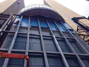
Figure 3. Vierendeel truss.
points for the various existing conditions around the building, and assess and reinforce the existing steel-framed structure for the new additional load of the LED screen and its back-up structure. The original building façade consisted of precast panels attached to the perimeter steel beams. Some openings through the panels had already been created to support light signage around the building. Since each of these openings are costly, connection points to the existing framing were minimized and, where possible, connections from previous signage and existing openings in the precast façade were used. On the north and south faces of the LED sign, corresponding to the 45th and 46th Street facades, the building columns are set back about 8 feet from the façade and cantilever beams extend from these columns to support the existing façade. The support of the new screen was created by extending the cantilever beams. In the instances when the cantilever beams were found not to have the additional capacity required to support the new loading, the beams were reinforced using top and bottom steel plates. The LED screen is five stories tall and is located between levels 3 and 8. The supporting framing for the sign along Broadway was divided into three sections (Figure 2). On the north and south sections, the existing façade was set-back from the property line; at these two areas, the hotel requested open-terraces overlooking Times Square to be constructed on the 8th floor. On the south side, moment frames were constructed along the property line that provided support to both the LED sign and the south terrace. On the north side, a combination of new framing along the property line and framing cantilevering out of existing columns was used. For economy, existing connections and precast openings were also used on the north and south sides of the Broadway facade. In the middle section, above level 6, the existing façade protruded and had to be demolished to install and support the LED sign. The framing in the middle portion of the Broadway façade consisted of hangers suspended from the floors above, and did not have the capacity to support the new load; therefore, the existing structure in this area could not be used. To accommodate the absence of connection points on this portion of the façade and satisfy the stringent limitations on the deflections of members supporting the LED screen, a vierendeel truss was used (Figure 3). The truss spans 57 feet horizontally and has vertical supports only at the existing columns at level 3. It is connected horizontally at only a few discrete points within its 75-foot height to reduce displacement produced by wind loads. The vierendeel truss was selected
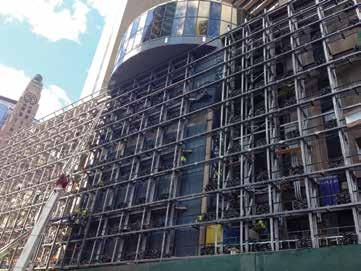
Figure 4. Installation of LED sign.
as the most efficient solution to span the distances between the supports, creating a structure that was robust for both the vertical load and the wind load. The LED screen consists of approximately 6- by 8-foot interlocking panels that connect to a secondary or back-up structure connected to the supporting structure described previously. The supporting structure had to be designed for the deflection limits required to accommodate the LED screen; however, it was also very important in the design to control the relative deflections at different support points within the width and height of the screen to avoid having issues during and after the installation of the screen panels. For this reason, sandbags with the same weight as the LED screens were stacked on the back-up structure of the LED sign, allowing for adjustments to be made before the installation of the LED screen and resulting in a successful procedure (Figure 4).
Interior Work
Achieving the developer’s intent to create ample top-quality retail spaces required the conversion of both underground parking levels and the first two above-ground levels into double-height spaces. To accomplish this, the cellar level and second floor were demolished, making the foundation wall and columns supporting the 44-story tower span twice their original design height (Figure 5, page 36). Both the columns and the foundation walls had to be reinforced; the column reinforcing consisted of plates welded to the column flanges, while the additional demand on the foundation wall was resolved by building a steel frame adjacent to the wall. This provided a mid-span support for the wall to bear on the dry-packed horizontal steel members of the frame. An important aspect of this work was to devise a sequencing scheme for the reinforcement of the columns and foundation wall that allowed for the demolition of the floor level and also ensured the safety of the structure at all stages. Different types of reinforcing options were evaluated. The main two factors that determined the column reinforcing used were that plating would cause minimum space intrusion and guarantee the stability of structure at all construction stages. The existing columns had the strong-axis capacity to span the two levels, however the weak-axis capacity was insufficient; therefore, the demolition and reinforcing scheme chosen consisted of initially demolishing only the deck and beams bracing the column on its strong axis, then providing
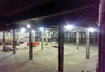
Figure 5. New double story space with reinforced columns.
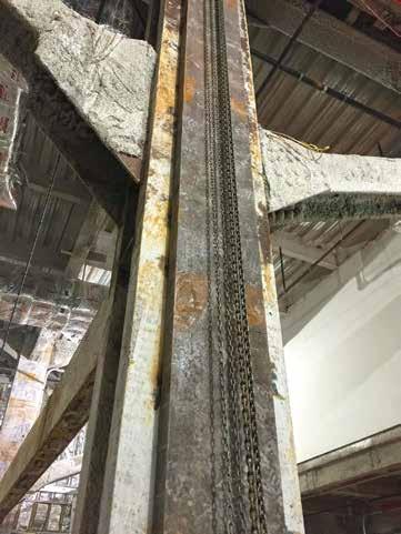
the flange plate reinforcing. Once the reinforcement was installed, the increased column section would have sufficient axial capacity in the weak axis to allow for proceeding to demolish the beams that were bracing the columns on the weak axis. That reinforcing scheme was typical at the two basement levels. Some of the columns on the first two levels above grade also had to be reinforced to allow for double height spaces. These columns were very critical to the structure as they were part of both a vierendeel truss lateral system for the building in one direction and a bracing system used for gravity in the other direction. The moment connected beam of the Vierendeel needed to be removed to allow for an open space. Since these columns were critical to the building, plating sequencing needed special care. Plates on each side of the beam were temporarily installed on the column to provide the required axial capacity. After the beam removal, a plate centered on the column flange was installed that would not protrude as much from the column as the temporary side plates (Figure 6). The structural interior work also included the floor demolition and design of new beams and reinforcing of existing beams to support stairs, as well as framing evaluation for infill loading at multiple locations in the building. The engineer also devised reinforcement solutions to meet head-height requirements, reducing the depth of a number of beams by as much as 1 foot.
Additional Challenges
Fortunately, the original architectural and structural drawings were available, which helped the design process significantly. However, as in all renovation projects, some conditions in the field are different
Demos at www.struware.com
Wind, Seismic, Snow, etc. Struware’s Code Search program calculates these and other loadings for all codes based on the IBC or ASCE7 in just minutes (see online video). Also calculates wind loads on rooftop equipment, signs, walls, chimneys, trussed towers, tanks and more. ($195.00). CMU or Tilt-up Concrete Walls Analyze solid walls for out of plane loading and panel legs next to or between openings by automatically calculating loads to the wall leg from vertical and horizontal loads at the opening. ($75.00 ea) Floor Vibration Program to analyze floors with steel beams and/or steel joist. Compare up to 4 systems side by side ($75.00). Concrete beam/slab Program to provide bending, shear and/or torsional reinforcing. Quick and easy to use ($45.00). Figure 6. Column reinforcing.
or not exactly as shown on the existing drawings. In some cases, electrical or architectural equipment was found to impede the construction of structural members as intended in the design phase, and changes to the design had to be made on multiple occasions to accommodate the existing conditions. Conditions found in the field made the work more cumbersome and challenging, requiring non-typical solutions. One example is a beam on the terrace floor that could not be connected to the existing framing adjacent to it due to conflicts. A member cantilevering out from an existing moment frame six feet away had to be used to support the edge of the beam, instead of the simple shear connection that would have been typically required. Besides the conditions found in the field, construction deadlines were also a big constraint, especially for the construction related to the LED sign, which had to be finished and running for a holiday completion deadline. For the swift progress and completion of the project, quick coordination among all team members and immediate solutions to conflicts during erection were necessary. The project’s success was due to the efforts of all parties involved in the design and construction phases to realize the owner’s vision.▪
Virginia Mosquera, Ph.D., P.E., is a Senior Project Engineer at Thornton Tomasetti in New York City. Virginia may be reached at VMosquera@ThorntonTomasetti.com.
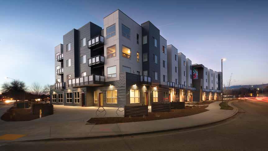
All wood. Mid-rise. Mixed use.
By Wilson Antoniuk, P.E.
The 951 is kinked at a radius of 21 degrees in the middle of the structure. Courtesy of Phil McClain.
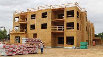
Boise, Idaho has been on numerous “Best of …” lists. This includes number four of “Best Cities to Live In” by Livability. com, number three for “Best River Town in America” by Outside Magazine, “The Best Cities for Men” by Men’s Health Magazine, and the lists go on. To capitalize on this trending city, developer and design architect Glenn Levie conceptualized and developed “The 951” building just steps from the epicenter of downtown Boise. His vision for the structure was to accommodate a unique land layout with a mixed-use space – all under one roof. The all-wood structure is four stories with 74,500 square feet. The first level is 4,100 square feet designed for retail space, with the remainder dedicated to 68 apartments on the upper floors. Seven of the apartments are two-story units that combine a street-level workspace – sometimes called live/work units – with private stairs leading to the living quarters above. The building design was unique and new for the Boise landscape, and one that included numerous engineering challenges along the way. Levie’s architectural vision for the structure had to make use of a land lot that curves with the street. The building is kinked at an angle of 21 degrees in the middle of the structure. The second floor is at a different angle from the first, and the main floor has a clerestory with two stories of open space above. According to AHJ Engineers’ project manager Craig Brasher, the design was further complicated by the first floor needing open area to fit commercial retail space and the upper floors being residential space. Different space usage created a unique design and structural challenge, as first floor walls do not align with the walls above. Furthermore, the apartments had window openings and jogged walls for patios – each floor has different wall jogs, some exterior patios over living space, some patios are cantilevered. The structural complexities of The 951 were varying and unique. To facilitate the projects’ success, General Contractor Steed Construction got their team together with the project engineer and suppliers to vet potential problems early and establish transparent lines of communication.
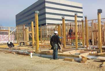
7x7 laminated veneer lumber and laminated strand lumber columns are set in place.
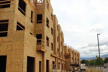
One of the first hurdles was to determine the construction material. The typical construction approach would be for a “concrete podium” design where the main level utilizes concrete walls with the second floor consisting of a suspended concrete slab, and then the floors above would be wood construction. Because of the architectural vision and plans that included the jogged window openings, the concrete podiums just didn’t make sense. There was a need for continuity of materials between all the floors, which wood construction could accomplish. The use of wood was a good solution since it is an economical and renewable resource, and there is regional subcontractor familiarity in working with wood that equates to labor savings during construction. In selecting the wood manufacturer, Brasher based his decision on the following capabilities: ability to manage multiple shop drawings and details, package and deliver laminated veneer lumber (LVL) and I-joist products based on the scheduled construction timeframe, and deliver a complete package. The complexities of the project needed the expertise of a wood manufacturer capable of field support and the organizational depth to problem solve unexpected issues.
Structural Design Challenges, So Many Unique Situations
The main level of The 951 was designed for different usage than that of the upper floors. The main floor required open, flexible space to attract commercial tenants. And remember, the second, third and fourth floors were designed for apartment usage. The result is that vertical loads needed to be concentrated into beams and transferred
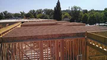
I-joists between the first and second floors. Courtesy of Steed Construction.
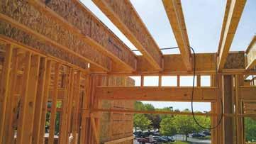
I-joists bearing at an exterior wall and a laminated veneer lumber header over a window opening.
ADVERTISEMENT–For Advertiser Information, visit www.STRUCTUREmag.org
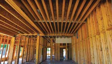
Laminated veneer lumber joists at 16 inches on-center support three stories of bearing walls above.
Carbon Summary Carbon Summary Carbon Summary
Results
VResults
V C
CC OO
O C O
Volume of wood products used: 880 cubic meters (31070 cubic ft) of lumber and sheathing
U.S. and Canadian forests grow this much wood in: 3 minutes
Carbon stored in the wood: 794 metric tons of carbon dioxide
Avoided greenhouse gas emissions: 1688 metric tons of carbon dioxide
Total potential carbon benefit: 2482 metric tons of carbon dioxide
Volume of wood products used: 880 cubic meters (31070 cubic ft) of lumber and sheathing U.S. and Canadian forests grow this much wood in: 3 minutes Carbon stored in the wood: 794 metric tons of carbon dioxide Avoided greenhouse gas emissions: 1688 metric tons of carbon dioxide Total potential carbon benefit: 2482 metric tons of carbon dioxide
Equivalent to:
Project Name: Date: Results from this tool are estimates of average wood volumes only. Detailed life cycle assessments (LCA) are required to accurately determine a building's carbon footprint. Please refer to the References and Notes' for assumptions and other information related to the calculations. 474 cars off the road for a yearEquivalent to: Energy to operate a home for 211 years
Results
Engineered wood packages are delivered to the jobsite based on the construction schedule.
Volume of wood products used: 880 cubic meters (31070 cubic ft) of lumber and sheathingV to columns. Lateral loads were also concentrated into beams and U.S. and Canadian forests grow this much wood in: 3 minutes transferred via the diaphragm to the o set walls below. e lateral loads added up to hold down forces of more than 27,000 pounds and shear wall forces greater than 1,000 plf. ese values Carbon stored in the wood: 794 metric tons of carbon dioxideC required double hold downs for the 2.0E LVL columns and sheathing on each side of many walls. e vertical load values required customfabricated base plates for the 2.0E LVL columns to avoid crushing Avoided greenhouse gas emissions: 1688 metric tons of carbon dioxide C OO wood sill plates. e hold down anchor bolts were embedded into the footings due to high forces and based on the ACI Appendix D calculations. e footings provided the concrete area necessary where Total potential carbon benefit: the foundation wall was too narrow to comply with Appendix D. 2482 metric tons of carbon dioxide e hold down anchor bolts going into the footings required special contractor layout instructions for eld placement.
Equivalent to:Live/Work Spaces Create
Unique Fire-Rating Requirements
474 cars off the road for a year Fire-safe construction for e 951 was complicated due to the mixed usage of the structure. e Type V-A construction required a oneEnergy to operate a home for 211 years hour re rated oor/ceiling assembly for most of the structure. e design team and building owner also wanted to create a oor and ceiling assembly that satis ed the IIC/STC/Vibration rating criteria that was economical and easy to build. To solve the problem, the manufacturer suggested a change in the I-joist size and on-center spacing. e change in design plans would achieve the required re rating and eliminate the need for two layers of gypsum board in the ceiling assembly. e revised plans required redesigning the second, third and fourth-level oor systems to a 24-inch on-center spacing of joists, in addition to increasing the
Project Name: Date: Results from this tool are estimates of average wood volumes only. Detailed life cycle assessments (LCA) are required to accurately determine a building's carbon footprint. Please refer to the References and Notes' for assumptions and other information related to the calculations. 474 cars off the road for a year Energy to operate a home for 211 years
Project Name: The 951 Date: November 19, 2015
Results from this tool are estimates of average wood volumes only. Detailed life cycle assessments (LCA) are required to accurately determine a building's carbon footprint. Please refer to the References and Notes' for assumptions and other information related to the calculations.
As an all-wood structure, The 951 contains: • 230,300 board feet of dimensional lumber to frame the walls • 5,800 sheets of OSB, including wall and roof sheathing, and oor decking • 31,200 lineal feet of I-joists, of various depths and series • 4,650 ft3 of engineered wood products including LVL, PSL and glulam Using the Wood Works Carbon Calculator, the amount of wood used in the structure is input and the output details environmental impacts.
joist ange to 1.5 x 3.5 inches – as compared to a 16-inch on-center with a 2.5-inch ange. ese changes met the one-hour re rating along with reducing the overall number of I-joists, hangers, and blocking required, thus also reducing the labor needed for installation. is is an excellent example of how framing intelligently can help keep material and labor costs down. e new I-joist on-center spacing provided the additional bene t of the larger joist cavities, which helped meet the acoustical criteria.
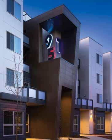
A clerestory balcony off ers unique curb-side aesthetics. Courtesy of Phil McClain. With a four-story structure, a two-hour fi re rating was required at the stairwells and elevator shafts. Th e two layers of gypsum board used to achieve this rating required unique I-joist hangers to perforate through the gypsum board and attach to the supporting LVL beams or walls. Once diffi cult to source, these hangers are becoming more common with the increased use of wood for mid-rise construction. Th e structural complexities of Th e 951 were varying and unique because of the awkward land layout, mixed-use space, and architectural vision. Th e engineering, construction, and wood manufacturer stakeholders communicated early and often to leverage each party’s expertise in solving the structural challenges. Th e result is a beautiful asset to Boise’s urban and contemporary live/work space that is sure to be one of Boise’s best.▪
From Boise, Idaho, Wilson Antoniuk, P.E., is a Technical Representative with RedBuilt™ LLC. Wilson can be contacted at WAntoniuk@redbuilt.com.
Project Team
Structural Engineer: AHJ Engineers, Boise, Idaho Developer and Design Architects: Levie Development Group,
LLC, Encino, California General Contractor: Steed Construction, Eagle, Idaho Engineered Wood Manufacturer: RedBuilt, Boise, Idaho
ADVERTISEMENT–For Advertiser Information, visit www.STRUCTUREmag.org


www.buysuperstud.com/Defl ectionClips or call 800.477.7883
US Patent 6213679; other patents pending


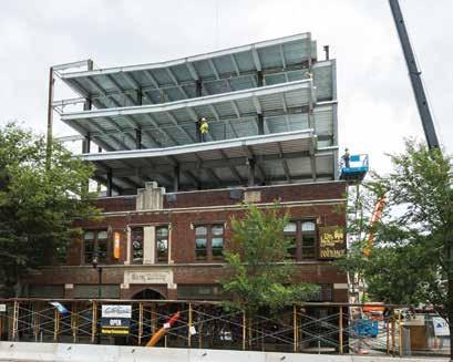
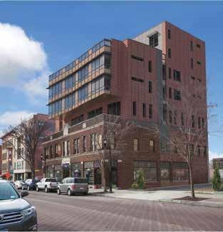
Figure 1a. Carey Building Southeast elevation during steel erection. Courtesy of Gary Hodges Photography. Figure 1b. Carey Building REVIT rendering of Southeast elevation. Rendering courtesy of John Snyder Architects.
THE CAREY BUILDING VERTICAL EXPANSION
By Joseph E. Caza III, P.E. and Michael Palmer, Ph.D., P.E.
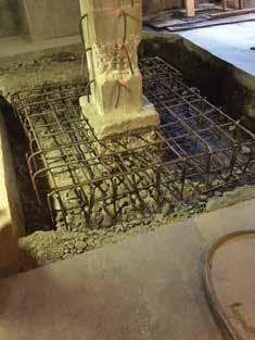
A22,000-square-foot vertical expansion is currently under forces, creating excessive building drift. To maintain the total drift construction at the existing Carey Building located at level to less than L/500, the design required a series of steel braced 314-320 East State Street, Ithaca, NY. The mixed-use frames to pass though the core of the existing and new building building, owned by Travis/Hyde Properties of Ithaca, is (Figure 2). The “overbuild” columns are located directly over the being expanded to accommodate new commercial space and residential existing reinforced concrete columns. To ensure a successful design, apartments while maintaining the current first floor retail space. The the existing structure required an extensive structural analysis to expansion involves the addition of five stories stacked above an existing locate building elements that needed to be bolstered to support the two-story reinforced concrete structure originally constructed in 1922. additional gravity and lateral loads. The expansion will increase the building height from 27 feet 2 inches The first phase of the project was to analyze and reinforce the existing to a height of 81 feet above finished grade. The unique design sup- foundation. Based on initial field investigations, the original foundaports the entire addition on the existing structure by locating the five tion was recognized to be composed of shallow caissons, possibly hand story frame directly over the existing concrete dug. Discovered during construction were columns (Figure 1a and 1b). An important three existing foundation types: strap footfacet of the project was the need to have the ings at the West wall columns, shallow caisson retail space on the first floor remain occupied foundations, and typical spread footings. The and open for business throughout the project. methodology used for the existing foundation The expansion or “overbuild” is composed of redesign, to ensure sufficient bearing capaca steel superstructure with 5½-inch lightweight ity and to mitigate unwanted settlement, was concrete floor slabs on 2-inch composite steel to ensure that the existing foundation did deck. The lightweight concrete system was not support any additional load. The founchosen to create a 2-hour barrier between dation loads increased from a typical load of floors without fireproofing the steel floor deck. 180 kips to a maximum total new foundaThe structure’s lateral restraint is provided by tion load of 360 kips. The decision was made a hybrid lateral force resisting system. The to support this additional load on the new concrete and masonry elevator shaft located foundation elements. The new design requires towards the North East corner of the structure the enlargement of the existing foundations provides the primary lateral restraint. Due to with reinforced concrete “footing extensions” the eccentric position of the shaft, which was doweled into the existing foundations (Figure required to provide the client’s prospective 3 and 4, page 44). tenants open assembly space at multiple floors, A primary concern was the amount of the applied lateral forces do not coincide with reinforcing in the existing foundations. The the center of rigidity of the shear wall system. Figure 2. Center core braced frame existing footing depths vary from 18 and 26 The consequence is additional lateral torsional at basement level. inches; therefore, the only reliable method of
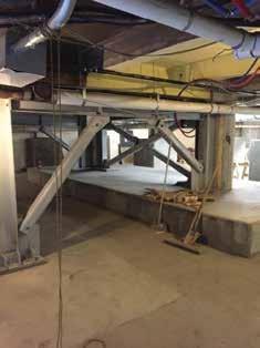
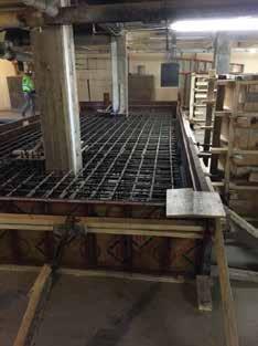
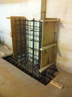
determining the size and location of existing footing reinforcing was by destructive testing. In lieu of extensive destructive field tests, the existing footings were treated as plain concrete when designing the footing extensions. With the assistance of a reinforced concrete collar used to supplement existing column reinforcement at the basement level, most of the footing extensions do not require an additional reinforced concrete “cap” over the existing footings. A concrete cap was required at one braced frame foundation (Figure 5). The additional concrete cap self-weight also serves to completely mitigate foundation uplift at this location. The second phase of the project was to reinforce the existing concrete columns. Ground Penetrating Radar (GPR) testing was successfully performed on each existing column, along with selective destructive visual inspections at each level, to evaluate the existing column reinforcing. The tests proved essential, as no reinforcing was detected in the lower portion of the basement level columns. To support an additional five-story steel structure, the columns were strengthened with a reinforced concrete collar. The collar consists of a 1-foot 4-inch reinforced concrete band wrapping the existing column (Figure 6). The original redesign called for a less intrusive stepped collar, but the as-built collar was found to be more constructible and still allowed for acceptable storage space. The reinforcement within the collar provides the much needed confinement of the existing concrete columns. The collar is also helpful to reduce the moment arm between the center of the existing assumed plain concrete footing and the new footing extensions. The third phase of the project was the placement of the elevator shaft foundation. The foundation was designed with the assistance of underground engineering specialist Brierley Associates, headquartered in Syracuse, NY. The elevator shaft is constructed of 12-inch cast-inplace reinforced concrete up to the new third floor level and 12-inch reinforced masonry to the roof level. As a primary component of the lateral force resisting system, not only is the elevator shaft tasked with providing gravity support for the adjacent framing, but also with resisting wind and seismic event forces. With an aspect ratio of nearly 8V:1H, bending controls the shaft design. Also, the slender elevator shaft walls introduce significant uplift forces to the foundation. To resist the uplift, (8) 8-inch diameter micro-piles were uniformly spaced around the elevator shaft foundation and socketed 25 feet
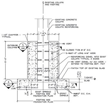
Figure 3. Footing extension reinforcing typical detail.
into bedrock located 30 feet below grade. Problematic to the design was how to transfer the uplift forces between the elevator shaft shear walls and the micro piles. The solution was to weld a series of ½-inch shear studs to the micro piles and extend the pile shaft directly into the elevator foundation walls, thereby lapping the pile casing with the foundation wall vertical reinforcing. The micro-piles also served a critical function during excavation for the elevator pit and pile cap. The elevator shaft is located within 2 feet of an existing column and in close proximity to the earth retaining exterior basement wall. The 8-foot deep excavation necessary for the elevator foundation would undermine both soil bearing elements. A plan was devised to create a support of excavation (SOE) system using the micro pile casings that would extend up to the basement floor elevation and become cast into the foundation wall (Figure 7). The SOE utilizes a typical soldier pile and lagging scheme, with the micro piles serving as the soldier piles. Six-inch WT standoffs were welded to the outside of
the soldier piles to create a void space between the lagging and the micro pile casing. The void space permitted concrete to flow between the lagging and the casing, completely casting the micro pile into the elevator shaft foundation wall. For the Structural Engineer, the design and development of a vertical expansion over an existing structure is a unique opportunity to preserve and reuse the original building’s form and function, while creating new space for a more comprehensive use of the building site.▪ Joseph E. Caza III, P.E. (jec@elwynpalmer.com) is a Professional Engineer and Associate with Elwyn & Palmer Consulting Engineers, PLLC of Ithaca, NY. Michael Palmer, Ph.D., P.E. (mcp@elwynpalmer.com) is a Partner with Elwyn and Palmer Consulting Engineers, PLLC of Ithaca, NY.
Project Team
Structural Engineer: Elwyn & Palmer Consulting Engineers, PLLC Owner: Travis/Hyde Properties, Ithaca, NY Geotechnical Engineer: Elwyn & Palmer Consulting
Engineers, PLLC Foundation Design: Elwyn & Palmer Consulting Engineers,
PLLC with Brierley Associates Architect: John Snyder Architects, Ithaca, NY General Contractor: Lechase Construction, Rochester, NY
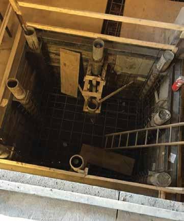
Figure 7. Aerial view of micro pile support of excavation at new elevator shaft.
ADVERTISEMENT–For Advertiser Information, visit www.STRUCTUREmag.org
RFEM 5
Structural Analysis and Design Software
German Engineering Precision
Designed for American Innovation
DOWNLOAD FREE TRIAL
www.dlubal.com
Dlubal Software, Inc. Philadelphia, PA (267) 702-2815 info-us@dlubal.com www.dlubal.com BIM Integration
Dynamic Analysis Non-linear Analysis
Meet Us There
Structural Congress - Phoenix, AZ February 14-16, 2016 NASCC - Orlando, FL April 13-15, 2016

Final plan of trusses.
Historic structures
significant structures of the past
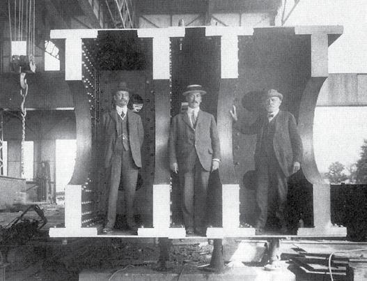
The newly accepted design of the Quebec Bridge maintained the 1,800foot main span with straight upper and lower chords on the anchor and cantilever spans. All of the parts, especially the lower compression chords, were much larger than the Phoenix Bridge/Cooper design. Instead of building the suspended span out from the ends of the two cantilever arms, they decided to build it off site and lift it into place. The suspended span was built starting in May 1916 at Victoria Cove, approximately three miles below the bridge, and was finished in July. The plan was to float it under the bridge and lift it into place, hanging it from suspenders attached to the ends of the cantilever arms. The span, with its length of 650 feet and weight over 5,000 tons, was floated into place on September 11 and connected to the lifting jacks. What happened next, if it hadn’t happened would not be believed, but the Quebec curse reappeared. The official report of the Board of Engineers, which now had H. P. Borden as a member, described the series of events on that fateful day.
“Preparations for floating were completed about September 1, 1916, but the range of tides, at this date, were not suitable. It was felt by the contractor, however, that several days could be spent to advantage in drilling their engineers and men in the various operations and in making a final inspection of the equipment and appliances. The next series of high tides occurred on September 11, and, weather conditions being favourable, the span was floated at Quebec Bridge 3:40 a.m. and by 4:40 a.m. it was being towed out into the river. Four small tugs and one large tug were attached Part 3 to the downstream side, with two small tugs upstream. As the tide was running strong, By Frank Griggs, Jr., Dist. M.ASCE, the tugs had little to do but guide the span D.Eng., P.E., P.L.S. on its trip up the river. At 6:35 a.m. the span reached the bridge site and at 7:40 a.m. the lifting hangers at all four corners had been
Dr. Griggs specializes in the restoration of historic bridges, having restored many 19th Century cast and wrought iron bridges. He was formerly Director of Historic Bridge Programs for Clough, Harbour & Associates LLP in Albany, NY, and is now an independent Consulting Engineer. Dr. Griggs can be reached at fgriggsjr@verizon.net.
Parts 1 and 2 of this article can be found in the December 2015 and January 2016 issues of STRUCTURE magazine. Visit www.STRUCTUREmag.org to read digital versions.
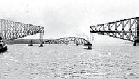
Suspended span collapsing into the St. Lawrence River.
connected. At 8:50 a.m. the jacks began lifting, and during the third lift of two feet the scows floated clear, leaving the span suspended about 20 feet above the water. After another lift of two feet, work was stopped to allow the men a period of rest and breakfast.
Up to this point the entire operation of floating the span and connecting it to the lifting hangers had worked exactly according to schedule. Nothing occurred that had not been foreseen and provided for. There was no wind, and every condition was favourable. As the work remaining to be done was simply a repetition of mechanical operations which had already been successfully performed, it was felt that most difficult part of the work had been satisfactorily accomplished.
At 10:30 a.m. jacking operations were resumed and one more lift made. The pins had been inserted connecting the lifting links to the fixed jacking girders, thus transferring the load directly to the cantilever trusses. The load on the jacks had been released and they were being lowered for another lift when, at 10:50 a.m., a sharp report was heard and the span was seen to slide off its end supports into the river.” Unlike the first failure where there were few eyewitnesses to the collapse, this time the press, photographers and officials of the government and the Board were on hand to witness the failure. Engineering News reported “many prominent engineers from the United States and Canada were on the suspended span when the lifting operations began. At the intermission in the jacking operations, they came ashore. That saved their lives...” They also reported that “both cantilever arms of the structure were thronged with many prominent engineers who had come to see the crowning achievement of the Quebec Bridge’s history.” The first reports of the failure came to Engineering News just before they went to press for their September 14 issue. Based upon limited information, they wrote: “The engineering world was amazed when the

Quebec Bridge 2008.
south cantilever of this great bridge fell nine years ago; but words are inadequate to express its sensations at the news that again this great bridge enterprise has suffered an unprecedented disaster.” Thirteen men were killed this time, with fourteen injured. Once again an intensive investigation into the cause of the accident was launched. It was clear to all that the truss had fallen off of the southwest supporting girder. The designers had used cruciform steel castings at each corner to provide for movements about two perpendicular axes. The investigating team was confident that this was the sole cause of the failure; but, to leave no stone unturned, they investigated three other possible failure mechanisms. The most significant was that of a “failure of the suspended span through some error of design.” Their conclusion was that the failure was indeed due solely to a failure of the casting. The ends of the cantilever spans had deflected seven and one half inches when they were subjected to the load of the suspended span. When the span dropped, the arms were seen “to spring violently upward, setting up severe vibrations and oscillations.” A thorough examination of the structure showed “no evidence of injury or distortion of any kind.” The engineering journals of the world wondered if it would be possible to “raise this span from the bottom of the river, in water about 200 feet deep?” No one had any thought that the span could be reused, but they were discussing reclaiming the truss for its scrap value. The Engineer, London wrote “the span has in all probability fallen more or less in position; and if it is found on inspection to be indeed worth saving, it is not impossible that the arms of the cantilevers may serve as cranes to raise it from the bottom.” This suggestion was not followed, and the span still rests at the bottom of the river. On September 13, 1916, the St. Lawrence Bridge Company accepted full responsibility for the failure and took “immediate steps to replace the span.” The bridge company was in the process of tooling up to make shells for the war effort, but still had enough of the original equipment available to fabricate a new truss which followed the same lines as the previous span with the exception that more nickel steel was included in the upper lateral bracing system. Carnegie Steel was able to fit in the rolling of the new steel for the span even though it to was actively involved in the war effort. The Board and the Bridge Company decided that the entire lifting apparatus would have to be rebuilt due to excessive deformations of the lifting links occasioned by the fall. Work on the new suspended span got under way at Sillery on June 4, 1917, with the span being completed on August 27. It was floated into place on September 17 or just over one year after the failure. This time, however, the erectors were even more careful than they were previously and had modified the end supports for the truss. The new device did away with the necessity for the second pin, which was responsible for the cruciform type of bearing originally used. The span was jacked and lifted into place over the next three days, with the final pins connecting the permanent suspension bars to the centre span being driven at 4 p.m., Thursday, Sept. 20, 1917. The Engineering News-Record which had just been formed by the merging of Engineering News and Engineering Record reported the moment as follows:
“The seventy-fifth lift followed immediately, and locomotive cranes were run out to all four corners with pin-driving cages and pins. At the end of the stroke, at 3:25, the first of eight pins was driven. The clearances were perfect, and each long pin slipped through its eye bars with a few taps from a short rail swung by about ten men. Every ringing blow of the rails stirred the onlookers. And when at 4 o’clock the last foreman shouted, “Right, here!” all restraint among workers and watchers was lost. The crane whistles on the bridge picked up the men’s cheers and the river boats passed the signal down to the City of Quebec, where (by the
Mayor’s proclamation) every whistle and bell and automobile horn was turned loose, and flags and buntings were thrown to the breeze everywhere, for Quebec realized that its dream of thirty years had come true.” continued on page 51


The Engineer, London wrote “one of the greatest, if not the greatest, feat of bridge engineering the world has ever seen was brought to a successful conclusion, on Thursday, September 20, 1917 at 4:01 p.m., when the 10-inch pin connecting the two sections of the Quebec Bridge to the ends of the cantilever arms were driven.” The Canadian Engineer proclaimed “Canadian Engineering Has Triumphed at Quebec.” The dedication of the bridge by the Prince of Wales was similar to that of the Firth of Forth Bridge 29 years earlier. This time, however, no one was knighted, as the project had been from its new start in 1908 a team effort. The main players were Ralph Modjeski who had been a member of the Board from the beginning, C. C. Schneider who had a connection with the bridge from 1907 when he was a consultant to the Royal Commission to his death in early 1916, and C. N. Monsarrat who was chief engineer for over eight years. The engineers, fabricators, and erectors of the St. Lawrence Bridge Company under the leadership of Phelps Johnson had built a bridge with a quality of workmanship unmatched in its day. The bridge was the product of American and Canadian engineering and bridge fabrication. It still carries railroad and highway traffic across the river. The lessons learned were hard ones, but never again would all the responsibility of a major project be placed on the shoulders of one, or even two men, but would be team projects with all members of the team working towards a successful completion. Checking at all stages of construction is now standard practice. Having men on the site during construction, with the authority to act, sadly lacking at Quebec, is also now standard practice. While it is still not possible to test full size compression members such as were designed at Quebec, we are able to test large members and through experience have designed many large compression members for bridges and buildings. As the result of the failure, the United States Congress authorized the construction of a $1,750,000 testing machine designed by A. H. Emery for the United States Bureau of Standards and installed it at the Watertown Arsenal. The bridge, with its 1,800-foot main span, was the longest span bridge in the world for many years and still is the longest span cantilever bridge in the world. In 1987, it was designated an International Historic Civil Engineering Landmark by the American and Canadian Societies of Civil Engineering.▪

State-of-the-Art Products
STRUCTURAL TECHNOLOGIES provides a wide range of custom designed systems which restore and enhance the load-carrying capacity of reinforced concrete and other structure types, including masonry, timber and steel. Our products can be used stand-alone or in combination to solve complex structural challenges.
V-Wrap™
Carbon Fiber System
DUCON®
Micro-Reinforced Concrete Systems
VSL
External Post-Tensioning Systems
Tstrata™
Enlargement Systems
Engineered Solutions
Our team integrates with engineers and owners to produce high value, low impact solutions for repair and retro t of existing structures. We provide comprehensive technical support services including feasibility, preliminary product design, speci cation support, and construction budgets. Contact us today for assistance with your project needs.
www.structuraltechnologies.com +1-410-859-6539
To learn more about Structural Group companies visit www.structuralgroup.com DUCON® trade names and patents are owned by DUCON GmbH and are distributed exclusively in North America by STRUCTURAL TECHNOLOGIES for strengthening and force protection applications. VSL is the registered trademark of VSL International Ltd.


