96 minute read
Advertiser Index


AZZ Galvanizing .................................. 39 Computers & Structures, Inc. ............... 52 Concrete Reinforcing Steel Institute ...... 13 CoreBrace, LLC .................................... 21 CTP, Inc. ................................................. 9 CTS Cement Manufacturing Corp........ 17 ENERCALC, Inc. ................................... 3 Engineering International, Inc. .............. 10 Foundation Performance Association..... 40 Fyfe ....................................................... 22 Halfen, Inc. ........................................... 19 Hayward Baker, Inc. .............................. 25 Integrated Engineering Software, Inc. .... 35 ITW Red Head ..................................... 37 KPFF Consulting Engineers .................... 6 NCSEA ................................................. 11 Polyguard Products, Inc. ........................ 33 Powers Fasteners, Inc. .............................. 2 PT&C Forensic Consulting Serv., P.A. .. 31 QuakeWrap ........................................... 24 RISA Technologies ................................ 51 S-Frame Software, Inc. .......................... 42 SidePlate Systems, Inc. .......................... 23 Simpson Strong-Tie............................... 29 Struware, Inc. ........................................ 14 Subsurface Constructors, Inc. ................ 20
Editorial Board
Chair
Jon A. Schmidt, P.E., SECB
Burns & McDonnell, Kansas City, MO chair@structuremag.org
Craig E. Barnes, P.E., SECB
CBI Consulting, Inc., Boston, MA Mark W. Holmberg, P.E.
Heath & Lineback Engineers, Inc., Marietta, GA Dilip Khatri, Ph.D., S.E.
Khatri International Inc., Pasadena, CA Roger A. LaBoube, Ph.D., P.E.
CCFSS, Rolla, MO Brian J. Leshko, P.E.
HDR Engineering, Inc., Pittsburgh, PA John A. Mercer, P.E.
Mercer Engineering, PC, Minot, ND Brian W. Miller
Davis, CA Evans Mountzouris, P.E.
The DiSalvo Ericson Group, Ridgefi eld, CT Greg Schindler, P.E., S.E.
KPFF Consulting Engineers, Seattle, WA Stephen P. Schneider, Ph.D., P.E., S.E.
BergerABAM, Vancouver, WA John “Buddy” Showalter, P.E.
American Wood Council, Leesburg, VA Amy Trygestad, P.E.
Chase Engineering, LLC, New Prague, MN
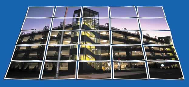
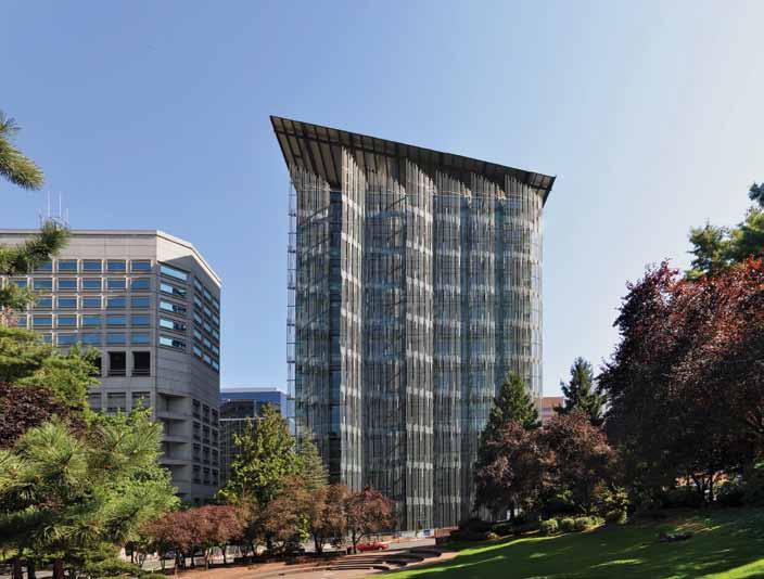
RENOVATION AND REHABILITATION, PORTLAND, OR — PHOTO BY ELIZABETH RICE Targeting LEED PLATINUM
Seattle Tacoma Lacey Portland Eugene Sacramento San Francisco Walnut Creek Los Angeles Long Beach Pasadena Irvine San Diego Boise Phoenix St. Louis Chicago New York
AdvErtising Account MAnAgEr
Interactive Sales Associates Chuck Minor Dick Railton
Eastern Sales Western Sales 847-854-1666 951-587-2982 sales@STRUCTUREmag.org
EditoriAL stAFF
Executive Editor Jeanne Vogelzang, JD, CAE
execdir@ncsea.com
Editor Christine M. Sloat, P.E.
publisher@STRUCTUREmag.org
Associate Editor Nikki Alger
publisher@STRUCTUREmag.org
Graphic Designer Rob Fullmer
graphics@STRUCTUREmag.org Web Developer William Radig
webmaster@STRUCTUREmag.org
STRUCTURE® (Volume 20, Number 7). ISSN 1536-4283. Publications Agreement No. 40675118. Owned by the National Council of Structural Engineers Associations and published in cooperation with CASE and SEI monthly by C3 Ink. The publication is distributed free of charge to members of NCSEA, CASE and SEI; the non-member subscription rate is $65/yr domestic; $35/yr student; $90/yr Canada; $125/yr foreign. For change of address or duplicate copies, contact your member organization(s). Any opinions expressed in STRUCTURE magazine are those of the author(s) and do not necessarily refl ect the views of NCSEA, CASE, SEI, C3 Ink, or the STRUCTURE Editorial Board.
STRUCTURE® is a registered trademark of National Council of Structural Engineers Associations (NCSEA). Articles may not be reproduced in whole or in part without the written permission of the publisher.
Celebrating years 1993-2013
C3 Ink, Publishers
A Division of Copper Creek Companies, Inc. 148 Vine St., Reedsburg WI 53959 P-608-524-1397 F-608-524-4432 Visit STRUCTURE magazine on-line at publisher@STRUCTUREmag.org
Visit STRUCTURE magazine on-line at www.structuremag.orgwww.structuremag.org Visit STRUCTURE magazine online at www.structuremag.org
inFocus new trends, new techniques and current industry issues The Intellectual Virtue of Engineering By Jon A. Schmidt, P.E., SECB
Based on the work of Allison Ross and Nafsikas Athanassoulis, I have identified safety, sustainability, and efficiency as “The Internal Goods of Engineering” (March 2013). Based on the work of Gene Moriarty, I have identified objectivity, care, and honesty as “The Moral Virtues of Engineering” (May 2013). However, I have also acknowledged the potential for dissonance among the individual goods or virtues in each list. How is an engineer supposed to harmonize them when that happens? One way to look at this issue is to recall that engineering involves the exercise of skill (“The Nature of Competence,” March 2012). Rules and maxims can help novices and advanced beginners learn to incorporate safety, sustainability, and efficiency into their designs; but it takes someone who has enough experience to be at least competent, if not proficient, to do so consistently. Successfully integrating all three could be seen as the mark of a true expert. Many philosophers have drawn a strong analogy between virtues and skills (“Virtue as a Skill,” May 2012), so the same terminology applies to those who characteristically exhibit objectivity, care, and honesty in the proper proportions. Ross and Atahanassoulis seem to agree, observing that engineers internalize these goods and virtues to the point that they are able to balance them rightly in particular cases, having developed “a reliable capacity to respond to risk with the appropriate attitude.” They affirm that “professionals acquire, through training and thought, settled dispositions to judge in accordance with their distinctive professional values and thus can be said to exemplify a kind of professional practical wisdom”; i.e., phronesis (“Knowledge, Rationality, and Judgment,” July 2012). This notion strikes me as closely related to a faculty that engineers constantly take for granted but rarely try to explain: engineering judgment. Michael Davis, a philosophy professor at Illinois Institute of Technology, addressed the challenge of delineating exactly what it is in a 2012 paper (“A Plea for Judgment,” Science and Engineering Ethics, Vol. 18, No. 4, pp. 789-808). As he says, “One who otherwise knows what engineers know but lacks ‘engineering judgment’ may be . . . a handy resource much like a reference book or database, but cannot be a competent engineer.” Similar to Ross and Athanassoulis, Davis defines judgment as “the disposition (including the ability) to act as competent members of the discipline act.” It involves more than just (theoretical) knowledge-that or even (technical) knowledge-how; it is “the embodiment of a high likelihood of making certain decisions in the appropriate way at the appropriate time.” Such judgment is neither arbitrary nor algorithmic, and the reference to peers as the benchmark is consistent with the legal notion of the standard of care – the level or quality of services that is ordinarily provided by practitioners of good standing in the same field under similar circumstances. Davis portrays judgment as the key to integrating ethics into any discipline that requires it. “Once we see judgment as central to the discipline, we can also see how central ethics is to its competent practice. There is no good engineering, no good science, and so on without good judgment and no good judgment in these disciplines without ethics.” However, Davis is quick to clarify what kind of ethics he has in mind and reveals a deontological orientation: “I mean those (morally permissible) standards of conduct (rules, principles, or ideals) that apply to members of a group simply because they are members of that group. Engineers need to understand (and practice) engineering ethics to be good engineers, not moral theory, medical ethics, or the like.” As Davis acknowledges, this approach – unlike that of Ross and Athanssoulis – treats applied ethics as a matter of technical rationality (techne), rather than practical judgment (phronesis). Despite recognizing that engineering judgment, like phronesis, is “a disposition to act in an appropriate way,” he defines the latter much more broadly as “the ability reliably to respond to any situation with a course of action that makes life better … Phronesis is (more or less) a global term; judgment is not global … We should speak of the art, craft, or skill of [an engineer] rather than his phronesis when he shows good [engineering] judgment.” Nevertheless, Davis explicitly wonders whether engineering judgment is a virtue, since it admittedly “is a disposition that contributes to living well (both to the engineer’s living well and to others living well).” Ultimately, though, Davis remains worried about the limited scope of judgment in this sense; as he notes, “The traditional virtues (courage, hospitality, truthfulness, and so on) concern the whole of life. No traditional virtue concerns only a single discipline as, for example, engineering judgment does.” Personally, I do not see this as a problem, given MacIntyre’s situation of virtues within distinct practices. Engineering judgment is, in fact, a discipline-specific form of practical judgment, which Aristotle classified as an intellectual virtue – importantly, the one that guides and ultimately unifies the corresponding moral virtues. As Moriarty summarizes:
Phronesis is at work in discerning and choosing appropriate goals of ethical virtue. Thus, ethical virtue without phronesis remains directionless. But, discernment of the good and perfection of deliberation are dependent on having good character. Hence, without ethical virtue, one might have cleverness in figuring out the means to any end, but one would not have phronesis, the virtue of choosing the appropriate means to the right end. This intellectual virtue of practical judgment – i.e., engineering judgment – is thus what makes it possible for engineers steadfastly to achieve their practice’s internal goods of safety, sustainability, and efficiency, while conscientiously exhibiting its moral virtues of objectivity, care, and honesty.▪
Jon A. Schmidt, P.E., SECB (chair@STRUCTUREmag.org), is an associate structural engineer at Burns & McDonnell in Kansas City, Missouri. He chairs the STRUCTURE magazine Editorial Board and the SEI Engineering Philosophy Committee, and shares occasional thoughts at twitter.com/JonAlanSchmidt.
STRUCTURAL PERFORMANCE
performance issues relative to extreme events ONCOMING WIND Along-Wind
Torsional-Wind
Across-Wind
Figure 1: Components of tall building response to wind excitation.
Structural design of tall buildings is driven by forces of nature, including wind and earthquakes. As buildings get taller, windinduced dynamic response dictates the design of the lateral system to meet both serviceability and survivability limit states. Structural engineers rely upon wind tunnel consultants to determine equivalent static loads (ESL) and Across-Wind Response of High-Rise Buildings top fl oor accelerations (TFA). This becomes increasingly important for tall and slender towers where across-wind eff ects Adjusting for Changes in dominate. After the building has been tested, the Mass and Stiffness structural design continues to develop, resulting in changes to the mass and/or the stiff ness. To By Rafi k R. Gerges, P.Eng, Ph.D., S.E., SECB, LEED AP, BSCP and Kal Benuska, P.E., S.E. quantify the increase or decrease in ESL and TFA, the structural engineer needs to send an updated set of dynamic properties to the wind consultant for a new cycle of post-processing. Th is article presents an alternative to this process in the form of design charts that enable the design engineer to adjust ESL and TFA for changes in mass and/or stiff ness. Th e interaction between the design team Rafi k R. Gerges, P.Eng, Ph.D., and the wind consultant could then be saved for S.E., SECB, LEED AP, BSCP, is a Project Manager at John Martin & Associates, Inc., Los Angeles, California. Dr. Gerges can be reached at rgerges@johnmartin.com. Kal Benuska, P.E., S.E., is a Principal Aerodynamic of John A. Martin & Associates, Inc., in Los Angeles, California. Fitted Relationship Mr. Benuska can be reached at benuska@johnmartin.com. f S M ( f )/σ 2 M major design milestones to confi rm wind loads and responses.
How does Wind Excite a Tall Building?
Under the action of wind, tall structures are loaded simultaneously in the along-wind, acrosswind and torsional directions as shown in Figure 1. Th e loads can be broken down into static loads due to mean wind pressure and dynamic loads due to fl uctuating pressure. Th e fl uctuating pressure induces two distinct responses; a low-frequency background component and a resonant component at the fundamental frequency of the structure. While all three sources contribute to the along-wind loading, only the fl uctuating wind pressure – the background and resonant components – results in the across-wind and torsional loadings. TFA is a result of the resonant response only. Th e mean and background components are primarily dependent on the building geometry and the turbulence environment, while the resonant response, in addition to geometry and turbulence, depends on the structure’s dynamic properties; mass, stiff ness and damping.
fp
Design Range
Frequency Ratio
Exposure B Exposure C Exposure D
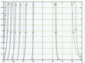
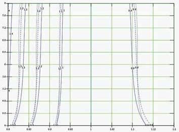
Figure 3: Upper bound for ESL adjustment factor for buildings with square floor plan. Figure 4: Lower bound for ESL adjustment factor for buildings with square floor plan.
o i a t R e c t s p A
Frequency Ratio
Exposure B Exposure C Exposure D
Does the Building Code Address All Three Components?
ASCE 7 provides a comprehensive treatment of the along-wind response of flexible structures based on the Gust Factor Approach. However, ASCE 7, similar to many codes and standards, provides no guidance on the across-wind response and limited guidance on the torsional response.
Are There Any Tools to Estimate Across-Wind Response?
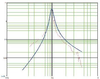
Over the years, wind tunnel testing has provided valuable aerodynamic data for the across-wind response. The across-wind spectra exhibits an evident peak around the Strouhal number, as shown in Figure 2. The Strouhal number is measured in terms of non-dimensional reduced frequency, f * = f x B/UH, where f is the natural frequency of the building, B is the building width perpendicular to the approaching wind and UH is the mean hourly
ADVERTISEMENT–For Advertiser Information, visit www.STRUCTUREmag.org
wind speed at the building height. The structural response peaks when f * matches the peak frequency (Strouhal number), fp. Tall building designers always tune the structural system to have a reduced frequency, at the strength level wind speed, that is greater than fp as shown in Figure 2. Relationships have been developed using curve-fitting to predict the across-wind Power Spectral Density (PSD) as shown in Figure 2, as well as the Root-Mean-Square (RMS) of the base moment coefficient. These relationships take into account the turbulence environment, building aspect ratio and building side ratio. In particular, the model by Gu & Quan is reported to produce a good fit for a wide range of buildings and turbulence environments.
How are Across-Wind Models Used?
Non-dimensional across-wind models can be used to compute wind-induced response of any structure having architectural features and a turbulence environment that are within the limits of the model. The model by Gu & Quan was calibrated for aspect ratios of 4 to 9, side ratios of 0.5 to 2 and four different wind exposures. Using this model, the upper-bound ESL adjustment factor chart is developed and is shown in Figure 3 (page 9) for buildings with a side ratio of 1.0. The adjustment factor is plotted vs. the frequency ratio (original frequency / new frequency) on the horizontal axis and the aspect ratio on the vertical axis. Similarly, a lower-bound ESL adjustment factor chart is shown in Figure 4 (page 9). Figures 3 and 4 indicate that the base moment decreases with an increase in the natural frequency of the structure, but increases more rapidly with a decrease in the natural frequency. This is consistent with the increased slope of the PSD as f * moves toward fp. The charts show a slight dependency on the wind exposure.
230
Structural Design Spreadsheets
www.Engineering-International.com
• Wind Analysis for Tornado and Hurricane Based on 2012 IBC Section 423 & FEMA 361/320.
• Mitigate Lateral Drift for Cantilever Column using Post-Tensioning.
• Moment Connection Design for
Beam to Weak Axis Column Based on AISC 360-10.
o i t R a s s M a
Frequency Ratio
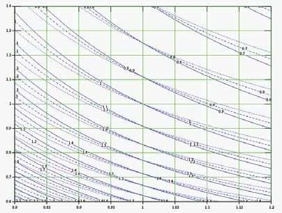
Exposure B Exposure C Exposure D Figure 5: TFA adjustment factor for buildings with square floor plan and aspect ratio of 7.
A TFA adjustment factor chart is shown in Figure 5 for buildings with a side ratio of 1 and an aspect ratio of 7. The adjustment factor is plotted vs. the frequency ratio (original frequency / new frequency) on the horizontal axis and the mass ratio (original mass / new mass) on the vertical axis. Figure 5 indicates that TFA decreases with an increase in frequency and/or mass of the structure, as expected. The dependency on the exposure is insignificant.
Design Example
Consider a 76-story residential concrete tower located in Los Angeles, California. The overall height of the building is about 260 meters (858 feet) with a square floor plan roughly 37 meters (121 feet) on each side. The wind exposure category is close to B as defined by ASCE 7. The lateral system consists of a reinforced concrete shear wall core with rigid outriggers (in one direction), and the gravity system consists of concrete flat plates supported by concrete columns. The resonant wind response, reported by the wind tunnel consultant, was mainly due to across-wind effects, with TFA of 18 milli-g. During the design development phase, the design team learned that the original target strength of 10,000 psi for concrete would not be achievable using local aggregate. The owner asked the design team to reevaluate the structural system using a maximum concrete strength of 7,000 psi. This concrete strength reduction resulted in a stiffness decrease of about 16%, which then reduced the natural frequencies by approximately 8%. Figure 5 shows an increase in TFA of about 12%. From a strength point of view, the force increased by approximately 12-18% based on Figures 3 and 4. Increasing the flexural strength of the shear walls was not an option due to seismic considerations in shear. The design team decided to add post-tensioning to the concrete flat plates in order to reduce their thickness by about 20%. This reduced the generalized mass by about 15%, restoring the building’s original fundamental frequencies so that the wind strength design could remain unchanged. However, the mass decrease also resulted in a TFA increase of about 20% per Figure 5. To deal with this, the design team proposed a damped outrigger system (90° to the rigid outriggers) to increase the sway mode equivalent damping ratio from 1% to 3% (in one direction), thus achieving TFA of 13 milli-g.
Conclusion
Changes in mass and stiffness during design affect a structure’s dynamic response to wind effects, which in turn require revisions to the associated equivalent static loads and top floor acceleration. Charts such as those in Figures 3, 4 and 5 provide a “quick and dirty” tool to estimate the impacts of such changes on strength and serviceability. However, confirmation from revised wind tunnel post-processing is still strongly recommended at design milestones. Engineered damping provides an economical alternative to meet serviceability (and possibly strength) design requirements, even at the final stages of structural design.▪
Practical SolutionS
solutions for the practicing structural engineer
H
WIND
HL
LV
L
RH
VR LV HL
L
RH
VR
(a)
(b) Figure 1: The direction of horizontal column reactions in a single-span rigid frame: (a) from gravity loads; (b) from wind or seismic loads.
Metal building systems (MBS), also known as pre-engineered metal WIND buildings, are proprietary struc H tures designed and manufactured by their suppliers. Metal buildings are extremely HL RH V popular and they account for a substantial per VL R centage of low-rise nonresidential buildings in the L United States. The design of foundations for these (b structures often involves ) special challenges. The Foundations for Metal Building Systems design procedures are often not well understood, because they are not specified in the building codes and technical Finding a Practical design guides. Until the recent publication of Solution for Your Project Foundation and Anchor Design Guide for Metal Building Systems (McGraw-Hill, 2013), there have By Alexander Newman, P.E., F. ASCE been no authoritative books on the subject. As a result, the foundation designs produced by different engineers for the same metal building structure could range from those that cost a trivial amount to those that are quite expensive to construct. This article discusses the reasons for such disparity and misunderstanding and examines the available design options.
Alexander Newman, P.E., F.ASCE, is a forensic and structural consultant in the Boston area. He is the author, most recently, of the Foundation and Anchor Design Guide for Metal Building Systems (McGraw-Hill, 2013). He can be reached at Alexander-Newman@ Outlook.com.
The Main Challenges
Several challenges make foundations for metal building systems different from those used in conventional buildings: • Single-story MBS are extremely lightweight. The total weight of the structure could be between 2 and 5 pounds per square foot (psf), which means that a strong wind results in a net uplift loading on the foundations. • The most popular types of the primary frames used in MBS – gable rigid frames – exert significant horizontal column reactions on the foundations.
Such reactions could be present in some conventional building foundations as well, but rarely at every column, and in combination with uplift. • Because MBS are proprietary structures, the manufacturers often report slightly different column reactions for the buildings with identical loading and configuration.
In the construction projects that use public funding and require competitive bidding, the MBS manufacturers cannot be selected prior to the foundations being designed.
Accordingly, the column reactions must be estimated by the foundation designers, running the risk that the final reactions will exceed those used in the design. • Unfortunately, in many situations the owner of the building decides to procure the metal building superstructure first and design the foundations later, as an afterthought.
Without a structural engineer involved in establishing the design parameters for the
MBS, some manufacturers might choose to provide the cheapest design possible. One such example is a building with fixed-base frame columns, which might result in minor cost savings for the manufacturer but in major cost increases for the foundation vis-à-vis pin-base columns. • The lack of clear design procedures naturally results in uneven design solutions. Some foundation designs for metal buildings have been overly complicated, and some have been barely adequate for the imposed loads (or not adequate at all).
Uplift and Horizontal Column Reactions
In single-story MBS, the dead load is generally insufficient to counteract the effects of wind-generated uplift. In addition, building codes require that no more than 60% of “the dead load likely to be in place” be used in combination with wind uplift (the International Building Code (IBC) “basic” load combination for the allowable stress design method). Thus the weight of the “ballast” must be substantial. For a typical shallow foundation, such as an isolated column footing, the “ballast” consists of the footing, column pedestal (if any), and the soil on the ledges of the footing. Some engineers also include a contribution of the soil frictional resistance.
Quite often, the minimum size of column foundations is dictated by the minimum amount of “ballast,” not by the soil-bearing capacity for downward loads. Th is often comes as a shock to the foundation designers unfamiliar with MBS specifi cs. Th e design example in the sidebar illustrates the process of sizing an isolated column footing for uplift. Gable rigid frames exert horizontal column reactions on the foundations. Th is occurs under gravity loading, when the reactions are numerically the same but act in opposing directions (Figure 1a), as well as under wind or seismic loading, when the reactions usually act in the same direction (Figure 1b).
Some Available Foundation Systems
Th e vertical and horizontal column reactions can be resisted by a variety of foundation systems, such as those listed below and illustrated in Figure 2 (page 14). Properly designed, each system can resist the required level of horizontal and vertical frame reactions. However, experience shows that some systems could be more or less applicable in various circumstances. Each system has advantages and disadvantages, as summarized in Table 1.
Foundation System Cost Reliability Versatility
Tie Rod Hairpins and Slab Ties Low to high Low to high Low to medium
Low Low Low
Moment-Resisting Foundation High High High
Slab with Haunch Medium Low to high Low to medium
Trench Footing Medium to high High High
Mat High High Low
Deep Foundations High High High
Th e table compares cost, reliability and degree of versatility of the selected foundation systems used in pre-engineered buildings. Here, reliability refers to the probability of the foundation system performing as intended for the desired period of time under various fi eld conditions. Th e most reliable systems can tolerate inevitable irregularities in construction, loading and maintenance. Th e overall reliability of a foundation system depends on three factors that defi ne the system’s ability to function in adverse circumstances: • Simplicity of installation. Th e foundations that are diffi cult to install or require a perfect installation tend to
be less reliable, because some placement errors are common and perfection in foundation construction is rare. • Redundancy. Redundant systems have more than one load path for transferring the column reactions to the soil. If one load path is blocked, another path takes over. • Survivability. Can the system maintain its load-carrying capacity after some of the adjoining building elements have become damaged? For example, what happens if the slab on grade is cut or partly removed?
continued on next page
ADVERTISEMENT–For Advertiser Information, visit www.STRUCTUREmag.org

Take Your Place In
The CRSI Honors
RECOGNIZING INNOVATION
in the Design and Construction of Reinforced Concrete Buildings by creating value in any of several ways: – Collaborative Design – Lean Building Methods – Uniquely Inspiring Spaces – Planned Use Adaptability – Material or Systems Efficiency – Whole-Life Sustainability – Structural Resilience
ACKNOWLEDGING THE LEADERS
at Every Stage that Drive Great Outcomes for Building Users: – Building Owners – Program Managers – Design Architects – Structural Engineers – Construction Managers – General Contractors – Construction Industries
Submittals will be accepted online from July 1, 2013 to November 1, 2013 Unlimited submittals per firm, entirely free to CRSI member organizations

HONORS
2013
Presented by

Versatility, as noted in Table 1, is possessed by the systems that can be used with various floor and soil conditions (e.g., floor trenches and pits). Some foundation systems commonly used in MBS are: • Tie rods (Figure 2a). In this intuitively appealing solution, the foundations at the opposite building columns are tied together, “extinguishing” both horizontal column reactions. Tie rod construction ranges from the cheapest and least reliable, such as a couple of reinforcing bars placed in a thickened slab, to the relatively expensive and much more reliable, such as concrete grade beams. The survivability of the former is low, because there is a distinct possibility that the slab on grade will be cut or partly removed at some point, while the grade beams placed below the slab will likely survive such a scenario. There are also the issues of elastic elongation of the tie rod under load and whether the tie rod is considered a “tension- tie member” under the provisions of the American
Concrete Institute standard ACI 318.
The versatility of this system is at the lower end of the spectrum, since tie rods cannot be used in buildings with deep trenches, depressions, and pits. • Hairpins with slab ties (Figure 2b). The general idea behind this design is the same as in the tie-rod system, but the tension force is resisted by distributed steel reinforcement in the floor slab (slab ties) rather than by discrete tie rods. This is the least expensive method of resisting horizontal column reactions and, for this reason, hairpins have been widely used in the past. But the system suffers from multiple disadvantages. Among them is a total reliance on the floor slab, which makes the system vulnerable to the slab being cut or partly removed.
Other issues include construction joints in slabs on grade, where the slab reinforcement generally stops, and even the fundamental issue of treating slabs on grade as structural elements. Slabs on ground are excluded from the scope of ACI 318, except when they transmit lateral forces from other portions of the structure to the soil. If the designer intends to have the slab on grade comply with ACI 318, the slab must be designed and constructed with greater care than the prevalent practices. At the very least, it should be reinforced more substantially than with a layer of light welded-wire fabric, to provide for a minimum percentage of “shrinkage” reinforcement. • Moment-resisting foundations (Figure 2c). These foundations work similarly to cantilevered retaining walls: the weight of the foundation, and any soil on top of it, resists overturning and sliding caused by external horizontal forces. Because it does not depend on a contribution of the slab on grade, the moment-resisting foundation represents one the most reliable systems available. It also is one of the most versatile, since deep trenches, depressions, and pits in the floor – or no floor at all – do not affect its function. The system can even be used in hillside installations, where one end of the building is lower than the
other. However, the design procedures for moment-resisting foundations are relatively lengthy and the construction costs could be high. • Slab with haunch (Figure 2d ). This system has been widely used in residential construction, and some have tried to use it for supporting large pre-engineered buildings as well.
The slab with haunch, also known as a downturned slab, works similarly to the moment-resisting foundation, and a rigorous design would result in the “haunch” of the size similar to the footing of the moment-resisting foundation. Needless to say, this is not the size the proponents of this system hope for. The reliability and versatility of the slab with haunch depends on whether the design relies on the contribution of the slab on grade. If it does, both reliability and versatility would be at the low end of the spectrum, similar to the hairpin system. • Trench footing (Figure 2e). In this design, a deep trench is excavated and filled with concrete. The resulting foundation could be made heavy enough to resist uplift and deep enough to develop passive pressure of the soil. Since the design does not depend on the contribution of the slab on grade, both reliability and versatility of this system are high. Obviously, the trench footings (also known as mass foundations or
StruWare, Inc
Structural Engineering Software
The easiest to use software for calculating wind, seismic, snow and other loadings for IBC, ASCE7, and all state codes based on these codes ($195.00). CMU or Tilt-up Concrete Walls with & without openings ($75.00). Floor Vibration for Steel Bms & Joists ($75.00). Concrete beams with torsion ($45.00).
FH Tie rod
(a)
FH FH Hairpin
FH Column pedestal
(b)
Slab ties
(c)
(d) Figure 2: Common Foundations Used in Metal Building Systems: a) Tie rod; b) Hairpins with slab ties; c) Moment-resisting foundation; d) Slab with haunch.
FHFH Slab onSlab ongradegrade
FHFH
(e)
FHFH Widen trench footing at columns
FH
(e)(e)
Widen trench Widen trench footingfootingat at columnscolumns
FHFH
formless footings) can only be used in the soils that allow for the excavated trench to be stable during construction.
This typically requires clayey soils. • Mats (Figure 2f ). Using mats might be advantageous in metal building foundations bearing on poor soils. According to one rule of thumb, when isolated column footings cover more than 50% of the building’s footprint, mats become economical. Mats are typically reinforced in two directions, both at the top and at the bottom.
Heavyweight mats work well in resisting wind uplift, and their continuous reinforcement solves the problem of
“extinguishing” the horizontal column reactions at the opposite ends of the frames. One challenge of using mats in metal buildings with multiple-span rigid frames is the placement of anchor bolts for interior columns. This often requires placing a separate “mud slab,” which can be used to temporarily support anchor bolts. Mats possess high reliability – they are unlikely to be cut casually – but a low versatility, because they do not work with deep trenches, depressions, and pits. Their cost is relatively high. • Deep foundations (Figure 2g). There are two main types of deep foundations: deep piers (also called caissons, or drilled shafts) and piles. Deep piers typically possess enough dead load to counteract moderate wind uplift.
If additional “ballast” is needed, a contribution of the perimeter grade beams could be considered. The grade beams also engage the passive pressure-resistance of the soil and thus help resist horizontal column reactions. Piles can resist both uplift and horizontal forces in a variety of ways, including friction in cohesive soils and flexure. Because deep foundations generally do not depend on a contribution of the floor slabs, these foundations are both reliable and versatile. But they are also costly and are typically used in only poor soils, particularly those where weak strata are underlain by competent materials. By understanding the advantages and disadvantages of various foundation systems used in pre-engineered buildings, designers should be able to select the foundation design that most closely matches the expected use, configuration and performance of the building as a whole.▪
(f)(f)
Figure 2 (continued): Common Foundations Used in Metal Building Systems: e) Trench footing; f) Mat; g) Deep foundations.
A Simplified Design Example for Sizing an Isolated Column (g)(g) Footing for Downward Forces and Uplift.
Given: Select the size of an isolated column footing to support an interior column of a single-story multiple-span rigid frame. The spacing of the interior columns within the frame is 60 feet; the frames are 25 feet on centers. The following loads act on the roof: 3 psf dead load, 30 psf design roof snow load, and 14 psf wind uplift. The depth of the footing must be at least 3 feet below the floor. The column is supported by a 20 inch by 20 inch concrete pedestal extending to the top of the floor. Use allowable soil bearing capacity of 4000 psf. Assume the average weight of the soil, slab on grade and foundation is 130 lbs/ft3. The building is not located in the flood zone. Use IBC basic load combinations. Solution. The tributary area of the column is 60 x 25 = 1500 (ft2). The design loads on the column are: Design dead load D = 4.5 kips Design snow load S = 45 kips Design wind uplift load W = –21 kips Total downward load D + S = 4.5 + 45 = 49.5 kips Total uplift load on foundation (0.6D + W ) = 0.6 x 4.5 – 21 = –18.3 kips Weight of the soil, slab on grade and foundation is 0.130 kips/ft3 x 3 ft. = 0.39 kips/ft2 (ksf) Net available soil pressure is 4.0 – 0.39 = 3.61 (ksf) Required area of the footing for downward load is 49.5/3.61 = 13.71 (ft2) For downward load only, the sign of the footing is 3.7 feet by 3.7 feet at a minimum. Check stability against wind uplift. Minimum required weight of the foundation, soil on its ledges and tributary slab on grade (Dmin, found) can be is found from: 0.6Dmin, found + W = 0
Dmin, found = 18.3/0.6 = 30.5 (kips) This corresponds to 30.5/0.130 = 234.62 (ft3) of the average weight of “ballast” With the depth of footing 3 feet below the floor, this requires the minimum square footing size of (234.62/3)1/2 = 8.84 (ft.) To reduce the footing size, try lowering the bottom of the footing by 1 foot. Then the minimum required square footing is (234.62/4)1/2 = 7.66 (ft.). To arrive at a nominal size, use 8.0 by 8.0-foot footing, with a depth of: 234.62/(8)2 = 3.67 (ft.). The final footing size is 8.0 ft. x 8.0 ft. x 3 ft. 8 in. deep, as controlled by uplift.
The complete version of this design example, including concrete design for various loading conditions, can be found in the new book, Foundation and Anchor Design Guide for Metal Building Systems (McGraw-Hill, 2013).
(g)
Codes and standards
updates and discussions related to codes and standards
In the CASE Business Practices article titled, “Too Many Codes Spoil the Design? Conflicts and Hidden Requirements Can Hurt You!” published in the September 2012 issue of STRUCTURE® magazine, Kirk A. Haverland wrote about a topic familiar to US engineers in the wind energy industry. Mr. Haverland describes the situation where a professional structural engineer “if presented with the opportunity to design a structure that is a little different” hopefully should be able to do his homework and “research the idiosyncrasies of industry practice, design requirements, different codes and standards, etc.” The piece further describes a problematic scenario where the building code (i.e., “Code” based on 2009 IBC and ASCE 7-05) may not necessarily govern the design. That is, various reference standards are in conflict, and design may be governed by undocumented and un-codified information known only to those engineers “in the know.” Unfortunately, this accurately describes the situation faced by US Wind Farm Tower Design engineers trying to engage in wind turbine support structure analysis, design and permitting.Introducing ASCE/AWEA The primary difficulty is the lack of a dedicated RP2011 wind turbine generator system (WTGS) support structure design standard. The US wind By Nestor A. Agbayani, P.E., S.E., SECB, M. ASCE and Rolando E. Vega, Ph.D., P.E., M. ASCE industry has been developing utility-scale wind farms for over three decades, and yet in that time there has been no clear guidance in the US for the design and permitting of WTGS support structures. The domestic wind industry utilizes foreign design standards used by the European wind turbine original equipment manufacturers (OEM) who had initially dominated the global wind energy market.
Nestor A. Agbayani, P.E., S.E., SECB, M. ASCE, is a Principal Engineer at Agbayani Structural Engineering. Nestor may be reached at nagbayani@sbcglobal.net. Rolando E. Vega, Ph.D., P.E., M. ASCE, is the Director of Renewable Energy Research at the University of Texas at San Antonio, Texas Sustainable Energy Research Institute. Rolando may be reached at Rolando.Vega@utsa.edu.
Introducing RP2011
In the absence of specific domestic design guidelines or standards, demonstrating Code compliance has been a challenge. In 2009, the American Society of Civil Engineers (ASCE) and the American Wind Energy Association (AWEA) formed a joint committee to provide US design guidance. This article introduces one of the results of that effort: a new reference document for the analysis, design and permitting of utility-scale wind farm towers titled ASCE/AWEA RP2011: Recommended Practice for Compliance of Large Land-based Wind Turbine Support Structures (Figure 1). RP2011 is a resource for structural engineers engaged in utility-scale wind farm tower design or permitting. The recommended practices are intended to help engineers establish an appropriate design basis for producing tower and foundation designs that meet established
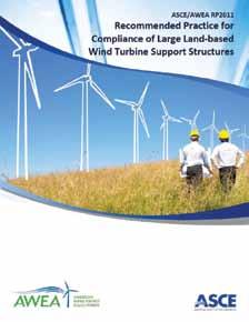
Figure 1: ASCE/AWEA Recommended Practice for Compliance of Large Land-based Wind Turbine Support Structures (ASCE/AWEA RP2011) © The American Wind Energy Association.
wind industry standards and that comply with Code. RP2011 is also intended to assist Authorities Having Jurisdiction (AHJ) who are responsible for permit process plan review of WTGS towers and foundations. RP2011 is available as a free download at the AWEA website: www.awea.org. As an example, this article will describe some of the major idiosyncrasies of wind industry structural design practice for WTGS steel fabricated tube towers. Applying conventional Code provisions alone as a design basis would likely result in an under-designed structure. Similarly, applying Code provisions alone for plan review compliance would be too permissive and give a “pass” to that same under-designed structure. It has been argued that the Code is a minimum standard for compliance and that the wind industry is free to meet a higher standard. Unfortunately, that argument is misapplied, since the Code minimum standard does not capture the correct governing structural design basis in terms of loading, WTGS behavior, and industry norms.
The Tower
The steel fabricated tube tower is currently the most typical structure type in use in the domestic and international utility-scale wind industries. While WTGS machine components may fail and be repaired or replaced through maintenance, the tower support structure must perform more reliably and without failure (Figure 2). At this time, RP2011 addresses only this tower structure type. To most engineers and others who are wind industry outsiders,
the tube tower appears to be a simple structure. In reality, structural engineers “in the know” understand that the simple appearance belies the inherent design complexities.
Primary Design Issues


Wind Design Typical application of the Code’s wind provisions would entail ASCE 7’s Section 6.5 Method 2 – Analytical Procedure. However, this loading may not be the governing wind loading for the WTGS tower. In fact, the Code’s extreme wind (1-in-50 year, 3-second gust) represents only one of many design load combinations (DLC) considered by the wind industry standard IEC 61400-1 published by the International Electrotechnical Commission (IEC). While the Code’s extreme wind may result in high design forces, the turbine OEM’s loads may contain other DLCs that produce even higher design loads that have no parallel in the Code, such as “turbine emergency stop” or “extreme annual operating gust plus electrical fault.” Code loading alone may be insufficient for WTGS tower design. Complete IEC WTGS design loading is obtained from a complex time series simulation, modeling the turbine’s proprietary aerodynamic, mechanical and physical properties. This analysis is usually performed by the turbine OEM’s specialists who compile the design loading into a comprehensive “loads document.” RP2011 Sections 5.4.8 and 5.4.9 provide strategies for reconciling building Code wind design loading with IEC site class extreme loading and recommends appropriate ASCE 7 design parameter values. Section 13 provides guidance on understanding the turbine OEM’s loads document. Section 14 also discusses the differences in wind speed and turbulence intensity profiles between ASCE 7-05 and that of the IEC standard wind site class definitions.


Earthquake Design Applying Code seismic provisions is immediately problematic because a steel fabricated tube WTGS support structure does not appear in ASCE 7-05 Table 15.4-2, Seismic Coefficients for Nonbuilding Structures not Similar to Buildings. Faced with this, the engineer may use engineering judgment to apply the R factor for a similar structure: perhaps a steel stack with R=3, an inverted pendulum with R=2; or a steel pole telecommunications tower with R=1.5. Note that “all other self-supporting structures …” with R=1.25 has a 50 feet height limitation in SDC D and greater, which would be

Figure 2: WTGS with steel fabricated tube tower. Courtesy of Rolando Vega.
too short for utility-scale towers. This is a reasonable approach, but there are other considerations. Virtually all utility-scale WTGS towers are thin-shell steel tubes whose design strength is governed by the limit state of local buckling and, therefore, they have very low ductility and little overstrength. Moreover, there are other unfavorable characteristics: the tower is a single member with no redundancy; the system is top heavy with the wind turbine concentrating up to one-half of the total system mass at the tower top; and, the tower itself has very little inherent structural damping. Finally, the Code earthquake load combinations do not capture the wind industry’s governing earthquake load combination. RP2011 Section 5.4.4.5 recommends the consideration of two earthquake loading conditions: • IBC-compatible loading: gravity plus earthquake. • IEC-compatible loading: gravity plus earthquake plus operational load. For the IBC loading, RP2011 recommends R=1.5 along with the Code design response spectrum adjusted to a 1%-damped spectrum. The earthquake load is used in Code seismic load combinations. The wind turbine is assumed to be at standstill, so there is no effective structural damping contribution from the turbine’s interaction with the wind in the form of aerodynamic damping. For this reason, RP2011 recommends adjustment of the Code’s 5%-damped design response spectrum to a level of 1% damping, resulting in an increase in spectral ordinates by a factor of about 1.4. continued on next page
CONSTRUCTION CEMENT FASTER
STRONGER MORE DURABLE 3000 PSI IN 1 HOUR
Speci ed Worldwide
ADVANCED TECHNOLOGY
• High bond strength • Low shrinkage • High sulfate resistance • Great freeze thaw durability • Long life expectancy • 65% lower carbon footprint
Available in Bags and Bulk
800-929-3030 ctscement.com
For the IEC loading, RP2011 recommends R=1.5 in conjunction with the IEC seismic plus operational load combination that considers the somewhat likely situation where the WTGS is operating in a power production mode when the design earthquake event strikes. In this case, the effective damping contribution from the operational turbine is considered sufficient to allow use of the Code’s standard 5%-damped design response spectrum. However, the operational load of the turbine must be included. One such operational load is the “emergency stop load.” In this scenario, sensors (accelerometers) within the operating turbine detect the excessive tower top motions induced by the earthquake event. The “emergency stop” protocol is triggered, engaging the rotor and yaw brakes to rapidly halt the turbine so that it can ride out the excessive tower top motions. It so happens that this creates large tower design loads. The industry idiosyncrasies do not end here, as there are different ways to combine the earthquake and operational loads. Without an actual full-blown time series simulation, in practice the engineer separately calculates the Code’s design seismic force and then combines these with the maximum operational loads provided by the turbine OEM. Recognizing that these peak loads do not necessarily occur at the same point in time nor in the same direction, RP2011 recommends a square-root-sumof-squares (SRSS) combination. In contrast, the IEC standard suggests an absolute sum of the peak loads, but it recognizes that this is conservative. Fatigue Design At this stage of the design, the engineer may have applied Code wind and earthquake provisions along with the additional related IEC criteria. Nevertheless, the tower or portions of the tower may still be under-designed because fatigue may be the governing design condition. Even if the engineer were to have applied American Institute of Steel Construction (AISC) fatigue provisions, the design would still be unconservative with respect to wind industry practices. RP2011 Section 7.3.1 describes and reconciles Eurocode (EN 1993-1-9) fatigue S-N curves with the AISC (ANSI/AISC 360-05) S-N curves. Section 7.3.2 discusses the additional fatigue safety factors required by IEC that do not appear in AISC. Sections 7.3.4 and 7.3.5 introduce the Miner’s Rule linear damage summation method and the fatigue damage equivalent load (DEL) concept, respectively. The point is worth repeating that fatigue often governs all or part of the WTGS tower. Frequency Separation Assuming all the aforementioned design calculations were performed, the engineer may assume that the tower design is complete. Unfortunately, it is still possible that the tower design may be completely unusable if it does not meet frequency separation criteria. RP2011 Section 5.4.7 states that “to avoid resonance, WTGS should be designed with sufficient separation between system natural frequencies and turbine operational frequencies.” The section provides separation criteria that are in current widespread use in the wind industry practice. Adequate frequency separation is an imperative serviceability condition for WTGS. Upon start of operation, a WTGS with inadequate frequency separation will undergo large and violent backand-forth resonant oscillations. Sensing this, modern turbines will then shut down, preventing any further power production. However, older turbines without such a detection system could reach resonant oscillations large enough to damage or fail the tower. Inadequate frequency separation is remedied during the tower design phase by thickening the tower shell or widening the overall diameter of the lower sections to stiffen the tower, thereby increasing the system mass and natural frequency. Design for Stress Concentrations Localized portions of the wind tower may still be under-designed. In particular, tower shell areas subject to stress concentrations, i.e., “hotspot” stresses, usually require thickening. For example, stress concentrations occur around wall penetrations such as doorways and cable openings. The wind industry utilizes specific methods of finite element analysis (FEA). RP2011 Section 7.4.2 references an International Institute of Welding (IIW) standard, which gives guidelines on FEA mesh sizes and recommended hotspot stress extrapolation functions.
Other Design Issues
Specialized Design Procedures RP2011 Section 7.4 briefly mentions specialized design procedures used in the wind industry for the strength and fatigue design of bolted ring flanges. These bolted flange design methods (such as the “Petersen Model” or “Seidel Method,” so named for their inventor) are more amenable to hand calculation in lieu of FEA. Foundation Design Like the tower, the WTGS foundation design has its idiosyncrasies. RP2011 Section 8.6.1.5 describes “ground gap” limitations that amount to additional overturning stability requirements. One ground gap criterion requires that under IEC DLCs such as normal power production, no ground gap (i.e., zero bearing pressure) shall occur at the foundation-soil contact. Stated differently, this means that the contact stresses under the entire foundation footprint must remain in compression. Another ground gap criterion states that under service extreme loads, the ground gap shall not extend beyond the center of gravity of the foundation bottom area. Fatigue design of a reinforced concrete foundation is atypical in conventional building design, but WTGS foundations must be designed for high-cycle fatigue loading. This includes anchor rods and non-prestressed steel reinforcement bars. RP2011 Section 8.5 mentions a few alternative international standards used in the wind industry.
The Future of RP2011
Although RP2011 is a first-of-its-kind design guidance document for WTGS support structures in the US, as a “recommended practices” document it is certainly far from being a design standard. At this time, there are two goals for RP2011’s future: (1) The first goal would be the evolution of RP2011 or its future successor document into a standard, specifically into an ANSI standard to give the document credibility in the structural engineering community. Next would be an effort to achieve the status of a “code referenced standard” in future editions of the IBC. This would give the standard some “teeth,” i.e., the regulatory authority of Code. (2) The second goal would be the incorporation of future research to address and improve current gray areas in design knowledge. These include the following topics: a more comprehensive scope to include alternative tower structural systems and materials; improved understanding of tower response to earthquake plus operational loads; better understanding of seismic response and performance at near-fault locations; effective supplementary damping systems; improved understanding of concrete anchor bolt resistance to fatigue; a reliability-based soil-structure interaction framework for Load and Resistance Factor Design of WTGS foundations and improved coordination with future Code editions.
Conclusion
WTGS support structure design is subject to many idiosyncratic wind industry practices. It is of critical importance that structural engineers and plan reviewers recognize that many of those practices are beyond Code (from international standards) and may often be above Code (more conservative). RP2011 is an excellent resource to learn about current wind industry design practices and un-codified requirements.▪

Appalachian State University (ASU) Boone, NC
Masonry has a New Edge.
And it’s called HALFEN FK4. Introducing a new adjustable shelf angle with a thermal break.
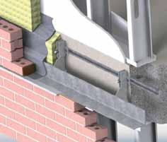
HALFEN FK4 brickwork supports transfer the dead load of the outer brick veneer to the building’s load-bearing structure: an eff cient construction principle developed with the experience of over 80 years of lasting technology. Adjustability HALFEN FK4 brickwork supports provide continuous height adjustment of +/- 13/8 ” which compensates for existing tolerances of the structure as well as installation inaccuracies of wall anchors.
Structural Effi ciency The HALFEN FK4 brickwork supports allow effi cient anchoring of brickwork facades in connection with HALFEN cast-in channels. Reduced Thermal Bridging The HALFEN FK4 brickwork supports are off set from the edge of slab allowing insulation to pass behind. Minimal contact with the building structure means reduced thermal bridging and lower energy loss.
Effi cient Design As the demand for higher energy effi ciency in commercial buildings continues to increase, the cavity between the brick veneer and the substrate is getting larger to allow for more insulation and air space. Along with this increased cavity size, the traditional masonry shelf angle, used to support the brick veneer at the slab edge, is also getting larger and subsequently heavier and more expensive to install. Architects & engineers are looking for a more effi cient support solution. The HALFEN FK4 brickwork supports use a thinner, light weight shelf angle, eliminating brick notching while also allowing for a wider cavity. Quality By using HALFEN FK4 brickwork supports, you profi t from an approved anchoring system, excellent adjustment options and a complete product program covering all aspects of brickwork facade.
Many advantages with one result: HALFEN provides safety, reliability and effi ciency for you and your customers.
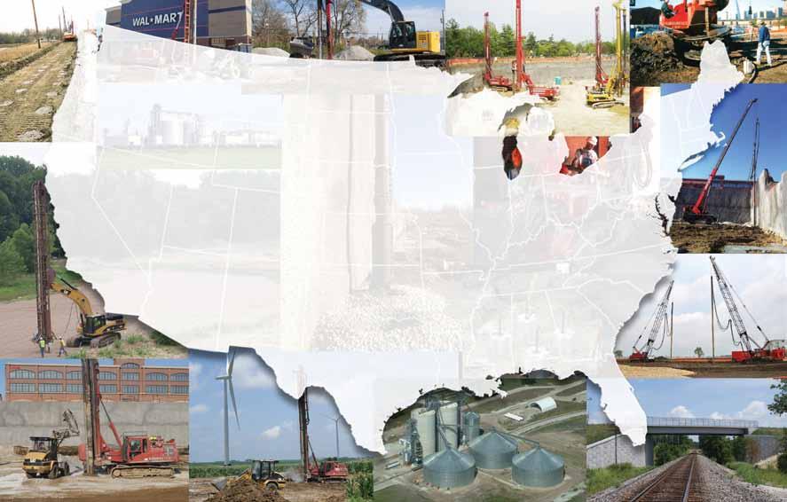


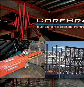
Growing Optimism Spurs Innovation for Seismic Companies
By Larry Kahaner


Growing optimism in the construction industry is bringing provide the most state-of-the-art performance levels and keep our with it new products and services, as companies o er more fabrication processes as economical as possible.” value and advanced features to keep up with customer Other companies see better times, too. “ e construction environdemand and their own competitors. ment is becoming more optimistic. It appears that, as the economy At West Jordan, Utah-based CoreBrace, LLC (www.corebrace.com), continues to recover, construction jobs are returning,” notes Aura Chief Engineer Brandt Saxey says that growth in the steel industry is Joyce, Marketing Communications Manager for Aegion Corporation increasing his sales. “We have continued to see strong growth in the (www.aegion.com), headquartered in St. Louis, Missouri and the steel industry and in particular the use of buckling restrained braces parent company of Fibrwrap Construction Services and Fyfe Co. (BRBs) within that industry. e use of BRB systems can bring the “One new and innovative application for the Tyfo Fibrwrap Systems overall construction cost for a building down, often helping to make on light-frame construction is the Tyfo G Wrap System,” says Joyce. the project more feasible and funding more available. Projects incor- “ e Tyfo G Wrap System utilizes advanced composite materials to porating BRBs often use less steel; o ering not only signi cant cost strengthen existing gypsum walls, and makes them behave like properly savings, but also contributing to true sustainability.” detailed plywood shearwalls. is is critical in strengthening existing e company supplies a large number of braces for typical buildings apartment buildings that su er from what is called soft story or weak such as schools, o ce buildings, and hospitals, but also provides braces story de ciencies.” She adds: “ e Tyfo G Wrap systems allows for for large industrial facilities, existing building retro ts, warehouses, the strengthening of these buildings by applying advanced composite bridges, and essentially any structure that an engineer might be materials over existing painted gypsum wall boards without having to designing, Saxey notes. “As the engineering community continues to tear into the wall. is allows for faster construction schedules and become more familiar with the behavior and advantages that BRBs provide, we see designers continually nding novel uses and new applications for them. is sometimes means that new kinds of performance requirements must be met from engineering and fabrication perspectives, which we work constantly to achieve.” Corebrace recently tested braces speci cally designed for bridge applications as well as near-fault earthquake e ects such as occurred in Christchurch, New Zealand. is testing included braces fabricated out of standard steel, galvanized steel, and stainless steel, and included both pseudo-static and dynamic rates of loading. Adds Saxey: “Each of these different material types produced a unique set of brace performance data, but each can be t for any project type. We’ve also recently tested braces designed speci cally for retro t use. ese braces are installed in two separate pieces and spliced in the middle, allowing them to be brought in ✔ Bolted, Pinned, and Welded Connections— Fully Qualified and Exceeding AISC 341 Requirements BUCKLING RESTRAINED BRACES WWW.COREBRACE.COM 801.280.0701 ADVERTISEMENT–For Advertiser Information, visit www.STRUCTUREmag.org and t-up in tight spaces where the use of ✔ Real-Time Engineering Assistance a traditional brace would not be possible. ✔ Non-linear Modelling Design Guides ese recently tested braces underwent some of the most rigorous testing we have ✔ Maximum QA/QC and Scheduling Control ever performed – far exceeding the AISC- ✔ Integration with RAM Structural System and REVIT 341 code requirements. Our ongoing ✔ New! “Near Fault Effect” Testing R&D program allows us to continually


limits the potential exposure of asbestos or other airborne particles that could be hidden within the walls of these buildings.” Also seeing an improvement is Lyle Simonton, Director of Business Development at Subsurface Constructors in St. Louis, Missouri (www.subsurfaceconstructors.com). “We are seeing a big increase in the use of ground improvement methods in the transportation and commercial sectors. We have performed the design-build of ground improvement solutions for MSE (mechanically stabilized earth) walls for several large DOT projects in several states,” says Simonton. “Additionally, we are seeing several of the big-name retail companies who are building new stores across the country require the use of ground improvement in lieu of remove and replace to speed up construction of these new stores.” At Subsurface, innovation is key, Simonton says. “As a specialty contractor, we must continue to innovate with our equipment and services so marginal sites can be improved economically, while trying to maintain a technological advantage over our competitors.” He adds: “Engineering consultants and the owners they’re working for seem to be spending more time than ever on trying to bring value to their projects. ey’re asking designbuild speciality contractors like us to work closely with them to develop valueadded foundation solutions, which often times means using vibro stone columns/ aggregate piers in lieu of deep foundations or substantial over-excavation.” (See ad on page 20.) Mo Ehsani, President of QuakeWrap Inc. (www.quakewrap.com) in Tucson, Arizona, says that a major concern in seismic retro t of structures is the strengthening and con nement of concrete columns. e company in the early 1990s introduced Fiber Reinforced Polymer (FRP) products which had been successfully used worldwide, he says. However, these repairs use the FRP in what is known as a wet layup procedure, where the fabrics of carbon or glass are saturated in the eld with epoxy resins and wrapped around the column. e method requires the column surface to be smooth, and in some post-earthquake repairs this may take additional time so masons can repair the damaged concrete before wrapping. e technique also requires trained contractors who have prior experience with these products. Now, Ehsani says that QuakeWrap has come up with a new generation of products called PileMedic that make these repairs much faster and easier. “We can now apply heat and pressure to saturated fabrics in our plant to produce a very thin FRP laminate sheet. ese sheets are four feet wide by hundreds of feet long and are sold in rolls. e challenge in this technique has been to make these sheets with thicknesses as little as 0.01 inch; the typical sheet is 0.025 inch and has a tensile strength in excess of 150,000 psi. e relatively exible sheets can be
formed to virtually any shape in the eld. In a typical installation, the sheet is wrapped twice around the column and glued to itself to create a very strong “sonotube”-like shell that leaves a small annular space. is annular space between the shell and the column is lled with grout. e entire operation takes about 1-2 hours.” Videos of these applications are available at www.pilemedic.com. “Like most engineers, we like to solve problems. So we’re continually researching and developing new ideas and asking ‘what can we do better?’.” says Henry Gallart, President of SidePlate (www.sideplate.com), Laguna Hills, California. “CJP welding is expensive and time-consuming, so SidePlate FRAME was developed as an easier way to realize the SidePlate design bene ts without having to do any CJP welds. It’s been a huge success by any measure, but many areas of the US still prefer eld-bolting. e SidePlate bolted connection was the logical follow-up to that.” Adds Gallart: “In April, we unveiled a new low-seismic, R=3 system that is eld-bolted. e industry response has been tremendous. For higher-seismic areas, just a few years ago we developed a new, more economical system called SidePlate FRAME, that uses only llet welds in the shop and eld. e eld-bolted connection is tailored to low-seismic applications and delivers the same SidePlate cost-saving bene ts to the overall design, but also solves many of the t-up issues inherent with other bolted moment connections. For higher-seismic applications, the llet-welded SidePlate FRAME con guration meets all of the AISC criteria for Special Moment Frames, saves cost on the overall design, and saves a signi cant amount of construction cost by eliminating CJP welding.” (See ad on page 23.) Jim Hussin, Director, Hayward Baker, Inc., (www.haywardbaker.com) headquartered in Odenton, Maryland, says that his company is involved in all industries and sectors since nearly all are confronted with geotechnical challenges. “Since its inception over 60 years ago, HBI has established itself in the forefront of geotechnical specialty contracting, evolving and expanding to meet the increasingly complex needs of the construction community. HBI is recognized by the industry to be reliable and innovative experts, and o ers full DesignBuild services for virtually any geotechnical construction application.” Hussin adds: “Soil mixing is a relatively new technology that is growing in use to solve issues related to soft soils and seismic applications. HBI has used this technology to improve ground for a wide variety of structures, especially those subjected to seismic and wind loading.” As for business conditions in general, he notes: “Although not close to the peak levels seen several years ago, Hayward Baker has seen a steady, healthy growth in the construction market over the past couple of years. Hayward Baker has a strong engineering sta and is available to assist SEs with evaluating geotechnical challenges and provide Design-Build services.”▪
STRUCTURE® magazine is planning several additional Special Advertorials in 2013 and 2014. To discuss advertising opportunities, please contact our ad sales representatives Chuck Minor and Dick Railton at
Sales@STRUCTUREmag.org
ADVERTISEMENT–For Advertiser Information, visit www.STRUCTUREmag.org


New York State Capitol Restoration

By Susan L. Knack-Brown, P.E. and Nicholas T. Floyd, P.E.
Figure 1: East elevation of the Capitol. Courtesy of Laurie Donald, Bernstein Associates Photographers, for OGS.
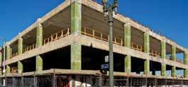
The New York State Capitol, designed in various stages by a succession of architects including Leopold Eidlitz and H.H. Richardson, was built between 1869 and 1899. Th is landmark building illustrates both Second Empire and Richardsonian Romanesque elements and is an architectural masterpiece with ornate carved stone, vibrant paint fi nishes and decorative glass, and decorative tiled fl oors. A number of monumental public spaces such as the Senate and Assembly Chambers, and three monumental staircases (the Assembly, Senate, and Great Western Staircases) help to architecturally defi ne the building. By the late 1990s, the building was losing its luster due to neglect, insensitive major modifi cations and chronic leakage, dating as far back as 1874, that damaged the exterior stone and interior fi nishes. In 1996, the New York State Offi ce of General Services (OGS) embarked upon a study to address the chronic leakage, which grew into a four-phase, 12-year restoration of the roofs and the three staircases, at a cost of approximately $85 million. Th is award winning project has fi nally addressed all of the reported leakage through the roofs, as well as restored to prominence the three monumental staircases by
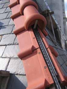
Figure 2a and b: Original mortar-set terra cotta hip installation and new system with stainless steel strut attachments. returning natural light and lost historic features to the spaces. Th is project’s success has also fostered other, separate restoration eff orts within the Capitol that continue OGS’s eff orts to restore the landmark to its original prominence. Accomplishing this project took a team of consultants and contractors from the initial investigation in 1996 through construction in 2012. Success involved a partnership of OGS, contractors, and the design team to ensure quality and craftsmanship befi tting this monumental building.
Architectural Terra Cotta Roofi ng
Th e Capitol has a complex roof arrangement, including several slate and clay tile roofs accented by architectural terra-cotta hips and railings (Figure 1). Th e original hung slate and clay tile roofi ng was replaced in the 1960s, incorporating decking and underlayment for added weather protection, but the terra-cotta was the original material dating to the late 1800s. Th ese terra-cotta units were mortar set directly onto the shingled roofi ng and steel bar stock framing (Figure 2a), and were a source of ongoing leakage that deteriorated the terra-cotta and mortar setting beds and corroded supplemental steel anchors. Prior to this roof project, tiles had been face-fastened with through-anchors and covered with sealant in attempts to address the attachment and leakage concerns; these repairs exacerbated the leakage and resulted in further cracking and degradation of the terra-cotta. Full replacement was deemed necessary. Th e replacement design required a water-tight system, with structurally sound attachments that maintained the original appearance and had durability comparable to the terra-cotta material (approximately 100 years). Th e design team elected to hang the new terra-cotta hip and apron tiles with stainless steel struts and attachment clips, which allowed for a drainable, water-tight copper fl ashing and continuous membrane underlayment below (Figure 2b). In order to attach these struts and provide a continuous substrate for the copper and membrane, the design included new steel framing and clips at each hip, ridge, and fi nial confi guration to carry the terra-cotta loads back to the existing metal roof structure. Th e existing roof planes and framing on the Capitol varied signifi cantly, so the design provided dimensional tolerances in the attachment system by use of the struts (allowing
Figure 3: Granite tower during installation of new substructure and after reinstallation of granite. Figure 4: Assembly Staircase attic before and after installation of new skylight, laylight, and staircase lighting. Before photo courtesy of Laurie Donald, Bernstein Associates Photographers, for OGS.
adjustability along the roof slope) and shims between the various attachment clips (allowing up/down adjustability). The individual terra-cotta tiles were also shimmed off the strut to accommodate variations in the tiles themselves. Finials and ridge tiles were set as more traditional stacked masonry with new stainless steel attachments.
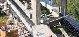
Pyramidal Granite Towers
The Capitol has four pyramidal masonry tower roofs, originally constructed with a granite exterior and a brick masonry vault backup. Chronic leakage plagued the rooms below these towers, which contained a combination of office space and rooms housing sensitive voting equipment and elevator machinery. A successful design solution needed to eliminate all leakage, while retaining the existing granite cladding, an integral part of the exterior appearance, and without relocating the equipment or machinery below. During the initial field investigation, it was observed that each course of granite included a back cut in the stone to interlock successive courses. While helping to interlock the tower structurally, this back slope channeled water runoff into the granite bed joints, exacerbating mortar deterioration and leakage. This systemic issue accounted for the previous pointing and sealant repairs’ failure to provide long-term relief from the ongoing leakage. The design team’s solution was to rebuild the pyramidal roofs as a typical masonry veneer, albeit on a monumental scale. Each pyramidal tower was deconstructed down to the cornice level and all granite units were salvaged, numbered, and stored for reinstallation. The towers were then rebuilt with a steel and precast pyramidal sub-structure on a reinforced-concrete ring beam designed to take the thrust of the new framing (Figure 3). New membrane and copper roofing, and through-wall flashing, were then installed for water management and the original granite was reinstalled with an open drainage cavity. The final appearance of the rebuilt tower exactly matched the original tower from the exterior.
Assembly and Senate Staircase Restoration
Due to safety concerns during World War II, the skylights over the three monumental staircases were painted black. Ongoing leakage through the then dysfunctional skylights prompted their later removal and overclad with copper or slate roofing. In the late 1940s, space pressures within the Capitol prompted the State to infill the upper reaches of the Assembly and Senate Staircases with offices. These major modifications showed little regard for the staircases, as the designs were now out of fashion, and many of the staircases’ iconic features were removed or damaged including hand-blown, hand-painted glass laylights, carved stone features, and decorative paint finishes. The roofing restoration work at the Capitol created an opportunity to replace the skylights over all three staircases and restore natural light to these remarkable public spaces. The Great Western Staircase was part of the first phase of construction. Work here included providing new modern aluminum framed skylights (including providing a new steel structure to support the side skylights where subsequent roof reconfigurations had removed the previous support framing), and restoring the glazing and paint on the original laylight frames that were still intact. The skylight and laylight were unveiled in August 2003. The success of the Great Western Staircases’ restoration paved the way for the state Office of General Services to pursue restoration of the remaining two monumental staircases. These two staircases posed an even greater challenge, as their restoration required removal of the infill construction, which included connecting corridors, floors, and the design and installation of new laylights to replicate the long-since removed original laylight framing and glass. Structural Concerns The staircases are constructed with load bearing masonry stairs and perimeter walls, and each is rectangular in plan with a long dimension of approximately 50 feet. The staircase roofs are constructed with long span iron trusses, perpendicular iron purlin members, and rafters which supported the original skylight glass but had since been modified to support wood decking and roofing. While there was little documentation of the original laylight framing grid pattern or attachment, the thick perimeter masonry walls are capped with a stone cornice that clearly supported the original laylight frame’s perimeter. Remnants of the original laylight framing hangers on the roof trusses were also identified. Using this information, the design team developed a gridded framing structure specific to each laylight that used the same methods of structural support as the original laylight frame (Figure 4). To meet building code requirements and contemporary performance expectations, the new laylight installation included an additional layer
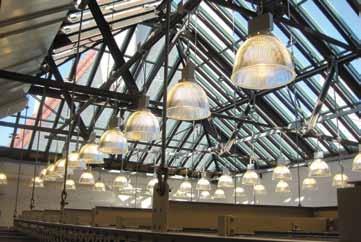
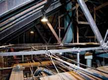
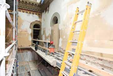
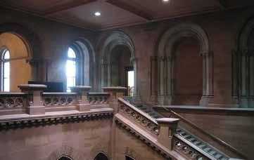
Figure 5: Assembly Staircase before and after restoration work. After photo courtesy of Laurie Donald, Bernstein Associates Photographers, for OGS. Figure 7: Senate Staircase before and after restoration of laminated glass as safety glazing, and the replacement skylight was a contemporary aluminum-framed system with insulating glass units, attached to the existing structure. These necessary upgrades increased work. After photo courtesy of Laurie Donald, Bernstein Associates Photographers, for OGS.the dead load of both the laylight and roof/skylight systems, both of which are supported by the original iron roof trusses. Using historical material property data, initial analysis indicated that portions of the original Senate Staircase would be overstressed by the new laylight and skylight loads. Material testing, including tensile testing, chemical analysis, and Rockwell hardness testing provided quantified material properties that allowed the design team to refine the design and confirm that the trusses could be reused with minimal additional framing to redistribute the loads. In addition to analysis of the new loads, the design considered the consequences of the load reductions resulting from the removal of the infill floor space. Portions of the Capitol already had reported settlement and foundation concerns due to the varved clay layer, and there were concerns that this load reduction could result in swelling of the clay that could cause damage to the existing masonry structure or interior finishes. Fortunately, in both staircases, the design team found that the infill construction represented a reasonably small percentage of the total staircase dead load, minimizing potential concerns. sandstone accents (Figure 5). Within the restored space, this staircase also included an ornately carved stone balcony and wood windows and doors looking into the space from the surrounding circulation areas. Unfortunately, all of these features, along with the laylight and skylight, were removed during the infill work. Restoring them required a careful preservation effort of documenting the painted-over colors and patterns; designing the new wood windows and doors based on remnants of the originals; replicating the detailed sandstone carvings that had been removed or damaged by the infill work; and designing a complimentary laylight based on limited original documentation. Restoring the balcony required not only careful architectural detailing of the carved stonework, but a creative structural design, as it was no longer feasible to deeply embed the supporting stone brackets and floor into the load bearing walls (as was done in the original design). The project design instead utilized a horizontal steel truss fastened to the surrounding masonry walls to support a sandstone stone cladding that mimicked Staircase Finish Work the bracket and floor slab appearance (Figure 6). The stone railing was The Assembly and Senate Staircases’ appearances are in stark contrast to each other. The Assembly Staircase is notable for its lavish, bright polychromatic painted plaster finishes, brightly colored laylight, and carved similarly reinforced with steel posts that were clad with sandstone. In contrast to the lavishly colored Assembly Staircase, the Senate Staircase is monochromatic and constructed with extensively carved red sandstone and capped with an opalescent glass laylight above (Figure 7). Similar to the Assembly Staircase, careful preservation efforts were required to replicate the damaged, intricately carved stone finishes and to clean the exposed stone of both general soiling and of mastics, markings, and staining left behind by the infill construction. The Assembly Staircase restoration was unveiled in January 2012. The Senate Staircase restoration, the final portion of the project, was unveiled by Governor Andrew Cuomo in January 2013.▪
Figure 6: Balcony steel frame and sandstone cladding installation during construction. Courtesy of Laurie Donald, Bernstein Associates Photographers, for OGS. Susan L. Knack-Brown, P.E., is a Principal at Simpson Gumpertz & Heger Inc. (SGH). Susan’s work includes a range of building enclosure investigations and designs, with a specialty in large-scale preservation. She can be reached at slknack@sgh.com. Nicholas T. Floyd, P.E., is a Senior Staff II at SGH. He supervised the roof restoration design and construction administration work on multiple phases of the Capitol restoration project. He can be reached at ntfloyd@sgh.com.


UW Uses Wood Framing to Meet Ambitious Design Goals on a Limited Budget

By Jennifer Cover, MS, P.E.
For the new University of Washington campus buildings, the design team used wood-frame construction to create a community with an iconic identity, exceptional energy effi ciency and integrated sustainability – all within a tight budget.
In 2012, the University of Washington (UW) completed a fi ve-building, $109 million construction project, adding nearly 1,700 student housing beds. Known as West Campus Student Housing – Phase I, the 668,800-square-foot project is the fi rst of four phases planned by UW to add much-needed student housing to its Seattle campus, which has an enrollment of more than 42,000 students. UW’s housing need is great, but budgets were limited since the buildings are owned by the University. Since Seattle’s building code allows fi ve stories of wood over two stories of concrete podium, Mahlum Architects worked with engineers from Coughlin Porter Lundeen to make the most of the urban campus location by using light-frame wood construction to meet both ambitious design goals and the University’s tight budget. As a result, the entire project was constructed for just $177 per square foot.
Traditional Wood Construction
Designed to connect students with their university, West Campus Student Housing – Phase I includes three residential halls (Alder Hall, Elm Hall, and Poplar Hall) and two apartment buildings (known collectively as the Cedar Apartments). Th e decision to use wood was made early in the design process. Mahlum Architects performed some initial cost analysis, even considering concrete at one point because they thought concrete was needed to provide thermal mass. But they quickly found that concrete’s higher cost did not justify the additional thermal mass, which drove their decision to use more cost-eff ective wood framing. All fi ve buildings in West Campus used a combination of fi ve upper fl oors of Type V-A construction over two lower fl oors of Type I-A concrete podium, which is a common construction type in Seattle. Th e two types were separated by a 3-hour rated fl oor assembly and all fl oors were fully sprinklered per NFPA 13. Th e fi ve upper fl oors used 2x4 and 2x6 wood studs in both exterior and interior load-bearing walls and partition walls. Interior shear wall assemblies included plywood sheathing. Floors consisted of engineered wood I-joists and plywood sheathing. Stair treads and stair landings on the primary staircases are constructed from glued laminated beams, and laminated strand lumber (LSL) is used for the rim boards. Roof structures are comprised of engineered wood trusses and plywood sheathing, and heavy timber blocking was used throughout for fi re protection. Th e building’s exteriors were then clad in manganese fl ashed brick extending to grade. Mahlum Architects added wood as a fi nish material on portions of the exterior to add richness and warmth to the material palette, especially around the main building entries. Inside, they used wood paneling, casework and trim for durability and to bring warmth to the public spaces.
Structural Design Strategies Started with Non-load-bearing Exterior Walls
Cost-eff ective design and engineering strategies started with a decision to make the exterior walls essentially non-load-bearing for all fi ve buildings; interior walls provided both primary structure and shear. With a few exceptions (e.g., at the corners) the strategy allowed the design team to space exterior wall studs at 24 inches on-center instead of 16 inches on-center. Th is saved money in material and allowed for more insulation, a decision that will help UW save energy over the life of the structures. In addition, the relatively random window pattern chosen, provided variable load paths in the exterior walls. Interior load bearing walls
alleviated the floor load from the exterior walls, which simplified load path calculations. The non-load bearing exterior walls also allowed for larger windows, which improves daylighting and reduces energy use over the long term.
Brick Fascia Required Careful Structural Detailing
All five structures were fully clad on the exterior with brick, which increased load demands on the structure. Framing members in the exterior walls supporting the brick were sized with a deflection limit of L/600. The design team took great care to make sure that the masonry to wood structure connection was engineered appropriately. Recognizing that shrinkage and compression occurs naturally with both wood framing and brick veneer (albeit at different rates), they anticipated the movement through proper detailing. The International Building Code (IBC) allows brick to be stacked up to 30 feet above the non-combustible foundation when there is a wood stud wall backing the veneer. Above that level, the brick has to be supported every 12 feet. However, to avoid problems caused by incompatible shrinkage between wood and brick systems, the West Campus Housing design team closely evaluated the wood building movement and then chose an interval to hang brick veneer that was specifically compatible with that analysis. They isolated the brick panels at each level by using veneer ledger angles hung from the rim board at each floor above the podium. So, the first story of bricks sits on top of the concrete foundation and is re-supported at the concrete podium slab and then at every level of wood floor framing. Brick wall gaps were detailed at every floor with enough tolerance to allow wood to shrink without causing the brick to crack. The design utilized a 3½ x 12-inch LSL beam set on edge, which spans the same dimension as the floor joist and extends between the interior bearing walls. The LSL carries the ledger angle, while also helping to alleviate the random load path around the windows in the exterior walls.
Seismic Protection
Lateral loading was also a consideration, since Seattle is in a high seismic area. Because wood systems are ductile, Coughlin Porter Lundeen engineers took advantage of wood’s flexible properties to meet the requirements. And, by combining the shear walls and the load-bearing walls, they were able to reduce the size of the required hold-downs. The staggered studs used for acoustical benefits (2x4 studs staggered on a 2x6 plate) also provided an additional advantage. Because the interior shear walls were stacked, floor-to-floor all-thread hold downs and multiple 2x6 compression studs were able to be used, which provided better strength. A standard 2x4 stud wall would not have been able to accommodate the larger 2x6 compression studs. The West Campus Housing design team’s decision to locate the main structural components in the interior of the building was a good strategy. Doing so allowed the designers to save money on materials; it allowed them to combine their shear walls with the load bearing walls, which reduced the size of hold downs.
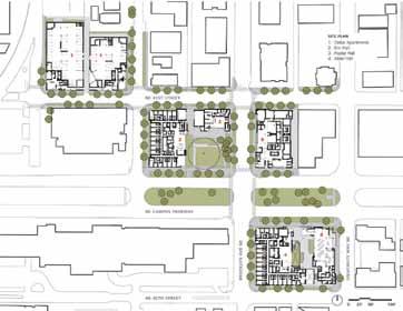
The first of four planned phases, the new UW campus project includes five buidlings, each with five stories of wood-frame construction over a concrete podium.
Acoustics
Acoustics are important for any multi-family housing unit, but particularly so for student housing. Mitigation measures must be weighed against the budget, which is why the design team brought in experts from Seattle-based SSA Acoustics. While the science of sound is fairly complicated, many mitigation measures are relatively simple. For example, SSA recommended a strategic combination of staggered stud and double stud walls to minimize sound transmission between residential units themselves, between the units and common spaces, and between the units and service areas. Because single stud walls would not provide adequate “sound” performance, SSA recommended staggered stud walls between residential units. Since there is no rigid connection between the gypsum board on each side (except at the plate), a staggered stud wall performs better than a single stud wall. Double stud walls perform better than a staggered stud design because plates are separated by an air space; so, double stud walls between residential units and common spaces (lounges, staircases, elevators, etc.) and service areas were used. Little details also count when it comes to acoustics, so all penetrations were sealed using resilient caulk. Whenever possible, junction boxes were located using minimum 24-inch spacing and back to back placement was avoided. When this was not possible, contractors placed putty pads on the backside of the junction boxes. In the floor/ceiling assembly, careful attention was paid to the installation of resilient channels, which are often one of the main causes of failed floor to ceiling assemblies from an acoustical standpoint. In fact, there is a difference of 8 to 10 IIC and STC points between
ADVERTISEMENT–For Advertiser Information, visit www.STRUCTUREmag.org STRUCTURAL ENGINEER (FORENSIC PROJECT ENGINEER)
Leading forensic engineering company is seeking experienced structural engineers for job openings across the U.S.
Offer: Responsibilities: Requirements:
• Competitive salaries • Comprehensive benefits • Provide residential & commercial site investigations to determine origin & cause of structural failures and damages • Investigate/assess damages due to natural catastrophes • Prepare detailed reports
• Professional Engineer license is required
• B.S. in Civil Engineering; M.S. Structural preferred • Min. of 5+ years design/structural engineering experience with commercial, residential, and industrial projects
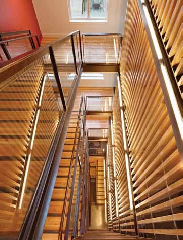
Wood was used as both a structural and finish material throughout the UW project.
assemblies with resilient channels versus those without. Channel installation has fairly straightforward requirements; for example, screws for the gypsum board should never touch the framing behind the resilient channel. Since carpet is the best material for reducing impact noise and footfall impact, carpet was installed throughout the West Campus complex (except in bathrooms and kitchens). Bathrooms and kitchens used a drop ceiling to accommodate ducting and plumbing, which provides additional noise reduction between units. Where the finish floor was stained concrete, a resiliently suspended gypsum wallboard ceiling was installed, using neoprene clips to reduce footfall impact noise below. Fire protection measures often benefit acoustical efforts. Where putty pads were required at electrical boxes for fire code (in 1- or 2-hour fire rated wall assemblies), there was no additional acoustical mitigation required. Penetrations through 1- or 2-hour-rated demising walls, corridor walls, shaft walls, floor to ceiling assemblies and others were sealed with fire resilient caulk, which also met acoustical recommendations. Structural changes were also implemented for acoustic performance. SSA increased live load deflection to L/480 (the code only requires L/360) on interior walls. They also recommended that plywood sheathing be placed only on the outer side (not the inner side) of double stud walls as the air space between layers of mass on each side of the studs is critical for achieving acoustical performance.
Moisture and Energy Management
Mahlum Architects used careful detailing and oversight to reduce envelope air infiltration and thermal bridging with continuous air, thermal, and moisture barriers. Their efforts made a significant impact on the buildings’ energy performance while also increasing the structures’ lifespan. The design team worked with an envelope consultant and the contractor to test full-scale mockups; they also did thermal imaging and conducted blower tests to measure infiltration. In addition, a number of simulation studies were performed to locate and size windows, maximizing daylighting and summer ventilation while maintaining winter comfort and minimizing energy loss through assemblies. Like many mid-rise housing structures, codes require a substantial number of air changes, which also helps avoid mold and moisture problems. Field testing was conducted to identify and correct any air barrier deficiencies. Their hard work paid off. Four of the five buildings in the West Campus Student Housing – Phase I meet the AIA 2030 Challenge (requiring 60 percent reduction over baseline fossil fuel energy consumption) with the purchase of green power. Cedar Apartments has already received certification at the LEED (Leadership in Energy and Environmental Design) Silver level, while Poplar Hall and Elm Halls earned a LEED Gold certification. Alder Hall is also on track to earn a LEED Gold rating.
Flexibility for the Future
The UW challenged their design team to create a community that could be built within a very tight budget, yet provide iconic identity, exceptional energy efficiency, and integrated sustainability to set the stage for future development. The decision to use wood as the primary structural material achieved all that and more. Wood framing also provided design flexibility, increased speed of construction, cut overall carbon emissions, and utilized local materials and a skilled labor force. Careful attention to detailing created an air- and watertight, thermally-efficient building envelope, providing long-term durability for the University. The five buildings are testament to the fact that wood construction can not only save time and money, but also create elegant, durable, urban structures that contribute positively to city and campus vitality.The West Campus Housing project represents a paradigm shift at the University of Washington, symbolizing its first embrace of large-scale light wood-frame construction.▪
Jennifer Cover MS, P.E., is National Director of the Architectural & Engineering Solutions Division of WoodWorks. Since 2006, she has also been an adjunct professor teaching timber design at the University of California, San Diego. She can be reached at jennifer@woodworks.org.
Project Overview
Project Name: University of Washington West Campus Student Housing – Phase I Owner: University of Washington Structural Engineer: Coughlin Porter Lundeen | Seattle, WA Architect: Mahlum Architects | Seattle, WA Acoustical Consultants: SSA Acoustics | Seattle, WA General Contractors: Walsh Construction | Seattle, WA WG Clark Construction | Seattle, WA Total size: 668,800 square feet (five buildings) Completed: July 2011 (Cedar Apartments and Poplar Hall) July 2012 (Alder Hall and Elm Hall)
Professional issues
issues affecting the structural engineering profession
While some of the more complex design, detailing and critical coordination on a building construction project occur at the interface of the structure and the building enclosure, building design teams often consider façade-system attachments as ancillary components of the project. In fact, design, fabrication, and erection of façade systems are often subcontracted out to a specialty contractor, who is part of the construction team. The specialty contractor’s team also typically includes façade system manufacturers, erectors, designers, detailers, and sometimes other various consultants. As a result of this arrangement, the project design team often delegates the façade-system and associated connection design work to the specialty contractor’s team. This allows the specialty contractor to consider efficiency and cost effectiveness of fabrication and erection in their design methodology. However, the specialty contractor is typically required to adhere to the overall design Façade Attachments intent outlined in project specifications and contract documents developed by the design team; this direction Who is Designing Them? may include specific requirements relative to overall system performance, loading, etc. The design By Filippo Masetti, P.E., team’s documents typically also provide guidMilan Vatovec, P.E. and ance on submittal and review procedures, as well James C. Parker, P.E., S.E. as general design-responsibility delineation; the design documents often also define specific portions of the design work that is delegated. Many Filippo Masetti, P.E., Senior Staff II at Simpson Gumpertz & Heger Inc. Mr. Masetti has been involved in numerous design, investigation, and rehabilitation projects involving concrete, steel, masonry, and wood structures. He may be reached at fmasetti@sgh.com. project documents, however, come a bit short and end up with general façade-related requirements that are a mix of prescriptive direction (e.g. where the façade is in plan and where it gets attached to the structure) and performance-specified direction (e.g. loads and deflection limits for façade elements and their attachments). Due to the delegated design arrangement, coordination is vital between the design professionals Milan Vatovec, P.E., Senior for the overall building project and the design Principal at Simpson Gumpertz & professional that performs the delegated design of Heger Inc. Mr. Vatovec is the head the façade systems. Without sufficient clarity and of structural engineering in the information in the design documents, as well as firm’s NY office. He may be reached coordination and follow-through during submitat mvatovec@sgh.com. tals, the design-responsibility demarcation line is James C. Parker, P.E., S.E., Senior Principal at Simpson Gumpertz & Heger Inc. Mr. Parker is the head of structural engineering in the firm’s LA office. He may be reached at jcparker@sgh.com. often blurred, and project deliverables, schedule, and overall quality can suffer; in worst cases, failures can ensue. This article provides a summary review of the current industry documents and their guidance on the topic, discusses the importance of clear delineation of design responsibility for façade-system connections and associated components, and provides some insight on how to potentially improve coordination between the design and construction professionals. In the upcoming sequel to this article, the authors plan to expand upon the topic, focus in some depth on specific issues, and discuss upcoming industry changes with respect to design (delegation) of facade attachments.
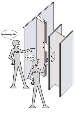
Review of Current Industry Standards
The following industry references provide broad information on the subject: 1) PCI Architectural Precast Concrete MNL-122, Third Edition, 2007 2) PCI Design Handbook MNL-120, Seventh Edition, 2010 3) PCI Connections Manual for Precast and Prestressed Concrete Construction MNL-138-08, First Edition, 2008 4) AISC Design Guide 22, 2008 – Facade Attachments to Steel-Framed Buildings 5) AAMA CWG-1-89 – Installation of Aluminum Curtain Walls, 1989 The majority of the industry reference documents emphasize the importance of coordination between the design professional (Engineer of Record – EOR, or Structural Engineer of Record – SER) and the design professional performing the delegated design (Specialty Structural Engineer – SSE). • As referenced in The PCI Deign
Handbook: “Coordination and communication between the […] SER and the […] SSE are of paramount importance. This aspect and its importance are recognized on the national level by the
Council of American Structural Engineers (CASE): ‘The primary failure in projects involving SSE is the lack of coordination

and delineation of responsibility.
When interfacing with the SSE, the SER should always be the one who delineates responsibility for the various structural requirements.’” (Para 14.5.4.3). Th e industry references describe the architect and/or the EOR (the design team) as those responsible for delineating the delegated work, for providing all design requirements relative to the delegated work, and for overall coordination between the delegated work and the rest of the project. Th e contract documents (drawings and specifi cations) are the means to convey this information. Th e following list of selected excerpts summarizes specifi c industry guidance on the topic: • Th e PCI Architectural Precast Concrete
MNL-122 states: “Th e design team should provide complete, clear, and concise drawings and specifi cations.
Contract documents should clearly defi ne: (1) precast concrete components that are to be designed by the precaster (state who takes responsibility for design of elements at interfaces with other parts of the structure, such as secondary steel bracing of the structure, to prevent rotation of beams or columns); (2) details or concepts of supports, connections, and clearances that are part of the structure designed by the design team and that interface with the precast concrete components; and (3) permissible design load transfer points and indicate generic connection types to avoid having the precaster make assumptions on connection types and piece counts during bidding and design.
It is preferable to leave specifi c panel and connection design to precasters so they can design details and connections suitable for their production and erection techniques.” (Para 4.1.2) • Th e PCI Design Handbook MNL120 states: “A critical function of the contract documents is to clearly defi ne responsibility among involved design professionals.” (Para. 14.5.3) • Th e AISC Design Guide 22 states:
“Th e structural drawings should delineate the structural steel elements from the attachment elements to be designed by the
Specialty Engineer.” (Para. 3.3) • AISC Design Guide 22 also states:
“Th e following is a list of potential problems that designers should be aware of and avoid when designing the support and anchorage systems for precast concrete wall panels… Lack of clarity in the division of responsibilities for designing and providing attachment and support components.
Responsibility for the design of miscellaneous angles, embedment plates, and similar items must be clearly indicated in the contract documents.” (Para. 8.10) Th e references above also point to the EOR to review the submittals relative to the delegated work for completeness and coordination with the contract documents. Th e following list of selected excerpts summarizes the guidance relative to the submittal review process: • Th e PCI Architectural Precast Concrete
MNL-122 states: “Th e Engineer of
Record (EOR) has the responsibility of reviewing the precast concrete design work for compatibility with the overall structural design and structural stability. Th is does not, however, relieve the EOR from the overall design responsibility for the safety and proper performance of the completed structure. Th e Engineer of
Record (EOR) should determine and show on the contract documents the locations for supporting the gravity and lateral loads of the precast concrete units, including intermediate lateral (tieback) connections, if necessary. Th e
EOR’s review of the erection drawings confi rms that the structure is adequate, within defi ned defl ection limitations, to resist the anticipated loads and forces from the precast concrete, and verifi es that the magnitude and location of the loading points on the structure agree with the original design intent.” (Para. 4.1.3) • Th e PCI Design Handbook MNL120 states: “[…] Th is does not relieve the EOR from reviewing the designs, ensuring that the designated loading requirements have been properly interpreted and interactive forces with other construction are fully coordinated.” (Para. 14.5.3) • Th e AISC Design Guide 22 states:
“Th e EOR reviews submittals by the
Specialty Engineer and the facade contractor specifi cally for the eff ect of the facade and its attachments on the primary building structure.” (Para. 3.3) • AISC Design Guide 22 also states:
“Th e SER normally has the design

Structural Software Designed for Your Success
* Easy to Learn * Analyze Anything * Design for: + Steel + Wood + Concrete + Aluminum + Cold-Formed * Friendly Support
www.iesweb.com
Free 30-Day Trial
IES, Inc. | 519 E Babcock St. Bozeman MT 59715 800-707-0816 | info@iesweb.com
responsibility for the following: …
The review and approval of shop drawings and field erection drawings for the effect of precast panels and attachments on the primary building structure.” (Para. 8.4) Finally, the references generally agree that the SSE is responsible for the design of the delegated system, but that this design is subject to review by the EOR. However, the design responsibility for the physical connections between the delegated system and the primary building structure varies among the reference publications. Examples of the industry’s attempts to draw the demarcation line between the delegated and the non-delegated components are summarized below: • The PCI Architectural Precast Concrete
MNL-122 indicates that the design of these interface connections is the responsibility of the delegatee: “The precaster designs the precast concrete panels and connection hardware for the design loads defined by the EOR and is responsible for selecting, designing, and locating hardware and panel reinforcement or items associated with the precaster’s methods of handling, storing, shipping, and erecting the precast concrete units. (Para. 4.1.5) • The PCI MNL-138-08 design guideline provides design examples for numerous types of precast-panel connections to the main structure.
All the examples show a list of the components of the connection for which design checks are performed.
In particular, the list of Example 6.5,
Bolted Tieback to Concrete or Steel Beam, includes the precast-panel embed insert, a connection rod connected to a steel angle, in turn welded to a plate embedded in the cast-in-place concrete.
This example considers the plate embedded in the cast-in-place concrete (part of base building) to be part of the precast-panel connection. • The AISC Design Guide 22 states:
“The Specialty Engineer is the design professional responsible for the design of the facade and/or its attachments to the structural frame. […] The Specialty
Engineer prepares calculations and drawings for submittal in accordance to the project specifications. The Specialty
Engineer is responsible for the design of the attachments.” (Para. 3.4) • The AISC Design Guide 22 also states: “The SER normally has the design responsibility for the following:
The design of the primary building structure, including the slab, slab edge detail, column, spandrel beam, roll beams, kickers, embedded bearing plates, etc., to support the forces imposed by the precast concrete panel system with due consideration to stiffness requirements… The precast manufacturer and SSE normally have responsibility for the following: …
The precast panel bearing and lateral connection design, including all supplemental hangers, kickers and other structural steel elements required to support the panels.” (Para. 8.4) • Finally, the AISC Design Guide 22 states: “The curtain wall manufacturer and the Specialty Structural Engineer
“normally have responsibility for … [t]he design of the curtain wall frame and its attachments to the primary building structure” and “[t] he preparation of shop drawings including details of all attachments to the primary building structure, types and locations of anchors clearly noted, and installation procedures and potential difficulties with field attachment considered and addressed in the shop drawings”. (Para. 9.4) • The AAMA CWG-1-89 states:
“Adequate anchor design is more likely to be attained if the curtain wall designer follows the load along its path from ‘start’ (e.g. glass or infill panel) to ‘finish’ (i.e. floor slab or spandrel beam). Often this tracking process will disclose potentially weak parts in the trial design.” (p. 26).
Conclusions
In summary, the industry points to the design team as the responsible party to safeguard adherence to the intent and requirements in the design documents, which includes compliance to the submittal-review protocols. In addition, the design team is expected to define, through their contract documents, which professional is responsible for what portion of the façade design, including its connections. In the absence of a clearly defined line of demarcation in the contract documents, the industry attempts to provide guidance to “fill the gaps” but, based on the authors’ experience, these attempts are often not sufficient to avoid potential miscommunication or issues on deliverables, schedule, and overall quality of the project. Situations where controversy can arise are usually related to different interpretations between the EOR and the SSE on where the façade components stop, and where the original building structure starts; for example, when façade-system anchors are embedded or post-installed into a column or slab of the main building structure, or when customized attachments connect a curtain wall to the main building structure. Based on the authors’ experience, as well as the authors’ interpretation of the intent of industry standards, the SSE (construction team) would be responsible for all facade-related connection design. Furthermore, the SSE’s design responsibility should include examining the ability of not only the connections themselves to resist loads at the actual point of attachment, but also to examine that the loads get into the building structural component (through the connection) without detriment to the structure. In other words, the SSE should examine the entire load path from the façade component through (and into) the building structural component. The SSE’s responsibility, however, should not include confirming that the base-structure component is able to resist the design loads in the ‘global’ sense (e.g. the overall bending moment, shear, and torsion demands on say a perimeter beam or column due to the façade-attachment loads); this responsibility remains with the design team. Unfortunately, unless the contract documents are very specific on defining the delineation between the responsibilities to this level of detail, room for interpretation remains, and potential for problems exist. Design gaps and/or blurred responsibility situations would generally be avoided if the design team would list (or indicate) in the contract documents all the items and components that are part of the delegated work, the performance and design criteria that the delegated work must satisfy, and all the submittals and associated procedures required for the delegated work. Design-delegation clarity would be further improved if, during the course of the project, the design team would also verify that all components of the delegated work are addressed by the construction team, and that reviewed submittals satisfy the performance and design criteria indicated in the contract documents. It is the authors’ opinion that an owner should always be able to rely on the experience and thoroughness of the design team to lead this process, even if the above arrangement is not required by the code or written into the design contract with the owner. In general, the design professionals should always strive to identify and prevent potential areas of controversy in the design documents, regardless if they are related to façade attachments or any other component of building design.▪


A Look at Insurance Options
Excess Versus Umbrella Insurance
By Gail S. Kelley, P.E.
Although the terms “excess insurance” and “umbrella insurance” are often used interchangeably, an excess insurance policy is not the same as an umbrella insurance policy. Both policies provide liability coverage, i.e. coverage that protects against claims of damage or injury to others or their property. Both increase the policyholder’s liability limits above those of specifically listed underlying policies and both protect against catastrophic risks, with coverage typically only provided in multiples of $1,000,000. However, excess liability policies only provide coverage above the limits of the underlying primary insurance; true umbrella insurance will provide coverage for additional risks.
Excess Insurance Coverage
Excess insurance policies can be either selfcontained (stand alone) or “follow form”. A self-contained policy has its own insuring agreement, conditions, definitions and exclusions; coverage applies to the extent described in the policy. In contrast, a follow form policy will simply state that it only applies if the loss is coverd by the underlying insurance. Coverage is subject to the same basic terms and conditions as the primary insurance. Neither self-contained nor follow form excess liability policies offer broader protection than what is provided by the underlying policies. In fact, excess liability policies, even those written as follow form, often have exclusions that make them more restrictive than the underlying coverage. Excess Insurance Limits Most excess insurance policies will increase both the each-occurrence limit and the aggregate (total) limit of the underlying policy. For example, if the underlying policy is a Commercial General Liability (CGL) policy with an each-occurrence limit of $1,000,000 and an aggregate limit of $2,000,000, an excess insurance policy for $1,000,000 would increase the eachoccurrence limit to $2,000,000 and the aggregate limit to $3,000,000.
Umbrella Liability Coverage
While excess insurance policies typically provide coverage for one underlying policy, umbrella policies typically provide coverage for several underlying policies. In addition, umbrella policies typically provide coverage not available in the underlying policies; such policies are often written in an “A/B format.” Coverage A represents excess coverage and is written to “follow form” the underlying policies. The policy increases the each-occurrence limits of the underlying policies and drops down when an underlying policy’s aggregate limit is exhausted or reduced by payment. Coverage B is the umbrella coverage; it applies when there is no coverage under an underlying policy. However, Coverage B will not apply to any claim for which applicable insurance is listed in the schedule of primary policies, even if the underlying insurance is uncollectible. In addition, Coverage B will specifically exclude coverage for various risks. Common exclusions are liability for asbestos, expected or intended injury or damage, workers compensation, aircraft, watercraft, unemployment compensation, pollution, liquor liability, contractual liability, damage to the insured’s product; and damage to property in the insured’s care, custody or control. Some umbrella policies also exclude coverage for professional liability. Coverage B is typically subject to the insured’s assumption of a self-insured retention (SIR). An SIR is similar to a deductible, in that it is the amount the insured is obligated to pay. However, when a liability policy has a deductible, the insurance company pays the entire amount and then bills the insured for the deductible. When the policy has an SIR, coverage does not begin until the insured has paid the SIR. In addition, deductibles usually only apply to judgements and settlements; an SIR usually applies to defense costs as well as judgements and settlements.
Umbrella Versus Excess Policies
Excess policies are sometimes designed to cover a risk that cannot be covered under an umbrella policy, such as liability arising out of the operation of a plane or high performance speed boat. Such policies are generally much more expensive than umbrella coverage in terms of premium costs versus amount of coverage. Excess insurance can also be used to bring coverage up to the limits required for an umbrella policy, or can be designed to “sit on top of” an umbrella policy to provide additional coverage for certain risks. Duty to Defend Excess policies are typically written such that the insurer has the right to defend against a claim, but is not required to do so. This is referred to as claim participation; a typical claim participation clause will state: “The Insurer may, at its sole discretion, elect to participate in the investigation, settlement or defense of any claim covered by this Policy even if the Underlying Insurance has not been exhausted.” If the excess insurer elects not to participate, the primary insurer must pay for the attorney fees and other legal costs to defend against a claim, even if the amount of the claim is such that the excess policy would be reached. Umbrella policies usually do include the duty to defend. Although defense coverage may be limited to occurrences not covered by underlying insurance, some umbrella insurance policies provide defense coverage once the limits of the underlying insurance have been exhausted. An example of when this might apply is when there are several claims resulting from the same occurrence. If the first claim is settled for the each-occurrence limit of the underlying insurance, the umbrella insurer would have the duty to defend against the additional claims. Sub-limits Liability insurance will often have specific sub-limits, such that coverage for certain risks is much lower than the policy limits. As an example, under a standard CGL policy, the coverage limit for fire damage to property leased by the insured is $50,000, regardless of the CGL each-occurrence coverage. Most umbrella or excess insurance policies do not drop down to provide coverage in excess of any sub-limits; specialty insurance is needed to provide such coverage.
Loss of Underlying Coverage Neither excess nor umbrella policies will drop down to provide coverage when the underlying insurer denies coverage because the insured did not comply with provisions of the underlying policy. Likewise, they will not drop down when underlying coverage is uncollectible due to insolvency of the insurer. The insured becomes liable for costs up to the limits of the underlying policy. In some cases, the underlying insurer may state that a claim does not fall within its policy and thus denies coverage. Rather than suing for coverage, the insured may prefer to settle with the insurer for some amount less than its policy limits. If the claim is such that an excess or umbrella policy would be reached, the law in most states holds that the insured is entitled to coverage under that policy once it has paid the limits of the underlying policy. Claims Against an Umbrella Policy Umbrella insurance with a policy limit of $1,000,000 will increase the limits of each of the underlying policies by $1,000,000. However, the umbrella coverage available for all of the underlying policies is reduced by the amount of any payment from the umbrella policy. A catastrophic claim on one underlying policy could completely exhaust the umbrella coverage for all of the policies. Nevertheless, the premium for an umbrella policy will be considerably less than the cost to increase the limits of each of the underlying policies by the amount of the umbrella policy. Umbrella policies are thus an attractive way to increase coverage, provided the risk of catastrophic claims is low.
Conclusion
There are no standardized forms for umbrella and excess insurance policies, and coverage definitions are developed by the individual insurance companies. As a result, excess insurance policies from different insurers can vary greatly in what they cover. For example, an excess policy might increase the limits of the each-occurrence coverage, but not the aggregate coverage. Likewise, when considering an umbrella policy, it is worth comparing several policies to see what additional coverage is provided and what defense costs are covered. Although insurers typically state that umbrella insurance will help close or eliminate “gaps” in the underlying insurance, policies tend to have a long list of exclusions. Some of the exclusions are reasonable because coverage is available under other policies, such as workers compensation and pollution liability policies. Other exclusions, such as damage to the named insured’s product or work, are viewed as a business risk that the insured should be responsible for. However, when all of the exclusions are considered, it may not be clear what additional risks are covered.▪
Gail S. Kelley, P.E., is a LEED Accredited Professional as well as a licensed attorney in Maryland and the District of Columbia. Ms. Kelley is the author of Construction Law: An Introduction for Engineers, Architects, and Contractors, published in 2012 by John Wiley & Sons. Gail would like to thank Keith Bouchard of CBI Consulting for his review of, and comments on, this article. Ms. Kelley can be reached at Gail.Kelley.Esq@gmail.com.
ADVERTISEMENT–For Advertiser Information, visit www.STRUCTUREmag.org