9 minute read
Historic Structures
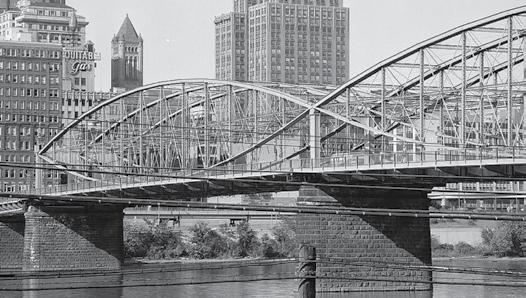
The superb lenticular spans and wide piers, seen from the west. It is the oldest and longest through-truss extant bridge in the U.S. HAER PA-Pitbu,58-9. Jack. E. Boucher, Photographer. 1974.
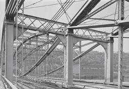
Interior through-truss with the third set of lenticular trusses of 1891 (left) first for horse-drawn trolleys, later for the 1898 electric trolley track. Lindenthal extended the bridge’s service life via planned, sustainable design. HAER, PA-2 Pitbu, 58-18. Jack E. Boucher, 1974.
significant structures of the past
Neither a fire, a worker falling 80 feet into the river (he was back to work the next morning), nor an ice floe tearing away part of the false work prevented or slowed the construction of one of this country’s most significant bridges. Gustav Lindenthal had enormous energy and drive. He received education to about age 14. Born in Brün, Austria in 1850, he worked in carpentry, railroad engineering, masonry, and other construction, rising quickly and eventually immigrating to America. A self-actualized learner, he absorbed every bit of knowledge in his midst. Nineteenth century Europeans had an inherent, sustainable approach to construction, emphasizing the use and reuse of durable materials (acquired locally if possible), efficiency, adaptability and elegant aesthetics. Lindenthal worked as a stonemason for the 1876 Philadelphia World’s Fair Centennial International Exhibition Memorial building’s granite foundation, and then rose quickly to a three-year stint as assistant engineer of construction for Philadelphia’s permanent centennial buildings. He then worked on bridge and rail projects, and by 1879 he called himself a bridge engineer. The iron and steel Smithfield Street Bridge replaced a weak suspension bridge – Roebling’s first highway bridge of 1845 – over the Monongahela River. Remarkably, Gustav Lindenthal constructed his new bridge with the old twenty-foot lower-clearance bridge remaining in service. False work was erected under the northern section of the bridge that both enabled one lane of the old bridge to stay in service during construction, and assisted in the erection of the six wrought iron plate girders for the new bridge. Some iron and machinery were retrieved from a proposed, but withdrawn, bridge at the same site, and efficiently reused here. Thus, source materials were conserved. The striking lenticular To Engineer is to Sustain (meaning a “lens” form of the truss-frames) throughtruss bridge constructed from 1881-1883 contains Gustav Lindenthal’s 1070 tons of iron in the superstructure and 322 tons in the foundation. The original one-bay-wide Smithfield St. Bridge carriageway is two 360-foot spans with trusses Pittsburgh, PA, 1883 comprised of 13 panels, each 27 feet, 71/2 inches. Wind and sun exposures are the same on all parts By Alice Oviatt-Lawrence of the superstructure: Lindenthal thus equalized the thermal expansion and contraction. The original bridge spans were 48 feet wide in 1883, leaving an eight-foot overage on the upstream side of the channel piers. Lindenthal designed the original bridge to accommodate future expansion up to 65 feet. He designed and Alice Oviatt-Lawrence is installed reusable, detachable sidewalks to flank principal of Preservation the carriageways, another example of sustain- Enterprises – an international ability evident in the project. architectural-engineering research continued on next page and historic-building analysis organization. Alice may be reached at strucBridge@aol.co.uk.
The online version of this article contains detailed references. Please visit www.STRUCTUREmag.org.
To raise the old bridge the required twenty feet for river traffic, Lindenthal integrated and added onto the substantial existing sandstone-faced piers partially constructed for the previously proposed but abandoned bridge. The pier centers are filled with concrete, followed by alternate header and stretcher stone-courses, of which each is iron clamped. Lindenthal adapted the 56 foot wide piers not only to elevate the grade of the original 1883 bridge, but also to prepare them for future superstructure expansion with associated loading, which he foresaw. The existing south abutment of concrete with sandstone facing was reused, but Lindenthal built a new north abutment. The north abutment has a stone backing sized about two or three feet wide by two feet thick by four-toseven foot-long stones, also laid in a header and stretcher pattern. All voids were filled and compacted with concrete, with the finishedface sealed with Portland cement.
The Steel
Just before this era, a new, locally manufactured “open hearth” carbon steel emerged, of a smoother and stronger quality than the equally available, but less-uniform, Bessemer steel or wrought iron. Metals were not standardized chemically or for mechanical properties until nearer 1900. Lindenthal tested all the materials going into his bridge, including the cements, the concretes and new steel. When most of the Bessemer steel failed in compression testing, the new steel was integrated into the bridge for the top and bottom chords, pier-posts, diagonal ties and pins. Of the total 1810 tons weight of the original superstructure, 740 tons are steel. In addition to the increased strength of the new steel, its price dropped from $166 per ton in 1867 to about $30 per ton in the early 1880s. Suddenly, steel-use meant economy both in terms of expenditure and for efficient selection of materials. Lindenthal saved $21,600 in construction costs by specifying the thinner, lighter, and stronger steel. The specified steel tested for compression at 50,000 to 55,000 pounds per square inch elastic limit, with ultimate strength of 80,000 to 90,000 pounds per square inch. Tests for members in tension proved to be 45,000 to 50,000 pounds per square inch elastic limit, with 70,000 to 80,000 pounds per square inch ultimate strength. Elongation, reduction of area at fracture and cold bending were analyzed via early U. S. testing methods and machines. The sounds generated by punching holes in steel plates and angles were scrutinized; an experienced ear could determine the firing temperatures, hardness and smoothness of finish. However, there was not yet an absolute scientific method to determine if there were flaws in metals.
The Structure
The structure can be visualized via two design concepts (parti): as an arch and cable structure, and/or as a schematic of the distributed loads. In the first, the upward thrusts on the upper chord ends (arch) are resisted by the pull of lower chord (cable). Lindenthal referred to the lower chord as a cable in 1883. In the second parti, the maximum strength is directly expressed at the truss mid-span, reflecting the greatest bending moment: The truss tapered-end form displays a diminishment of bending moment to near self-equilibrium at the end posts. The wrought iron vertical web-members transfer loading from the deck to the upper and lower chords, acting in tension vis-à-vis the dead load and the evenly distributed live loads. The verticals act in compression only when the load is unevenly distributed. Lindenthal selected iron here, as the weight was no different than that of the steel web members of the same dimensions. The adjustable steel eyebar and turnbuckle diagonal web members stabilize the arch and cable system under a variety of distributed loadings, and contribute to the forming of the shape. Each diagonal increases in cross sectional area from the panels nearest the end supports to the mid-span panels. While Lindenthal and others describe the bridge as a triangulated Pauli-truss, Thomas Boothby and others mathematically prove that it is a “parabolic lenticular truss bridge”. Lindenthal himself compares a “sine-curve” arc to a circle arc and, after studying circle arcs and parabolic arcs, he states that the difference between the two is a negligible 21/2 inches. The two truss-ends of the 13 irregularly shaped panels of the lenticular span trusses, where they converge, are supported by a middle pedestal on the pier. The entire assembly is rigid and is fixed cable-to-floor via non-adjustable, stiffened, iron suspenders
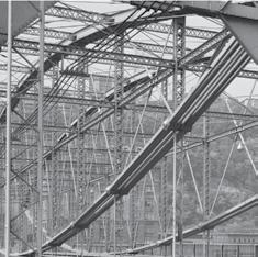
Close up of steel plate top and bottom chords, acting as arch and cable. The wrought iron vertical members are seen, with the horizontal intermediate bracing at midpoint running the length of the bridge. HAER, PA-2 Pitbu, 58-18. Jack E. Boucher, 1974.
A portion of Lindenthal office ‘stress sheet’ or technical drawing: “ Elevation and Plan of the Channel Spans”. In Transactions of the ASCE, Vol. XII, Plate XXIV. Sept. 1883.
to prevent vibration and to create an 18-inch camber to the floor assembly of each 360-foot span. Each steel end-post rests on a six-inch pin, bearing on a cast iron pedestal. This allows some friction-restricted rocking. No roller bearings were used at the pier posts. The bottom chords, consisting of eight to ten eyebars of varying thicknesses, were placed and the iron vertical web members connected in sequence from the ends. Then the steel plate top chords, weighing seven to nine tons each, were placed on the verticals working similarly in from each truss end. A block and tackle pulled the top and bottom chord-ends together into the lenticular form. The top chord is comprised of a box section made up of ten and twelve inch steel-riveted plates and angles, and increases in cross sectional area toward the end posts.
Post Construction
The iron rusted immediately. Even after scraping the rusty areas with lime pastes, subsequent ample applications of iron oxide primer and lead paint mixed with raw linseed oil did little to protect the bridge from Pittsburgh’s harsh environment.


Lindenthal 1881 office illustration: “View of the Two Channel Spans”, showing the massive one-bay-wide, original steel-supported and embellished with iron portals, under a three-bay-wide arcade supporting a mansard roof. Transactions of the ASCE, Vol. XII, Plate XXII. Sept.1883.
In 1889-1891, with traffic growing apace, Lindenthal was commissioned to add another set of trusses on the upstream side to double the carriageway: one for a publictransit horse-drawn trolley track, and the second for private horse-drawn carriages. Later, in 1898, one truss set was moved to accommodate a new, wider electric trolley. Simplified portals framing the two bays were added in 1915. This was all easily accomplished due to Lindenthal’s original master planning and foresight. Lindenthal’s intentional design for conservation of resources, adaptability of construction, expansion potential, and repair of the structural elements has extended the bridge’s service-life. The floor system was replaced in 1933 with structural aluminum-alloy. Lindenthal (d. 1935) likely approved of the material change, as it embodied his goals of integrating emergent materials of equal or better strength, and of the lightest possible weights, into the bridge. The Smithfield was rehabilitated in the mid 1990s, at which time the deck was replaced and the bridge painted. The iron structural members require inspection for potential widespread microscopic-cracking and capillary action of water leading to corrosion. Inspection data submitted to the Federal Highway Administration by the State DOT in 2010 indicate that the bridge is holding up well even under a daily traffic load of 6400 vehicles, including continued public transit, and with countermeasures in place to control a scour issue. With continued inspection and maintenance, the 129 years old Smithfield Street Bridge will continue to exemplify significant, sustainable construction.▪

For more on Gustav Lindenthal, see the Great Achievements article in the August 2010 issue of STRUCTURE magazine (www.STRUCTUREmag.org).


