30 minute read
Structural Design
Oversized and overweight Rough Terrain (RT) and All Terrain (AT) commercial cranes are used extensively at dam projects, and continuously cross bridges that serve the requirements of the public agencies or private utilities that own them. Depending on the state jurisdiction, these cranes will be trailored or driven under a variety of local and multistate permit programs. The effects of crane loads on bridges are a frequent concern due to the variability in age, design, construction, and condition of the bridges. Currently, the only guidance available for analysis is criteria outlined in AASHTO Load and Resistance Factor Design (LRFD) Bridge Design Specifications and AASHTO Guide Manual for the Condition Evaluation and Load and Resistance Factor Rating of Highway Bridges (LRFR). The information presented in this article will help determine safe loading capacity and placement of several types of classifications of oversized cranes on a bridge. It is based on vehicular loading and requires an analysis methodology that extrapolates an allowable crane permit loading from the bridge design or legal loading. The differences between vehicular & crane live and static loads, axle configurations and load placements are discussed. There are recommendations for making informed decisions on adjustments in impact loads, live load distributions and lane loading based on the strength and service requirements outlined in the evaluation and rating procedures in the AASHTO LRFR and LRFD specifications. This article will also present an outline for planning a crane operation on a bridge that includes consideration of working loads, placement and minimizing risks.
design issues for structural engineers
Current Design Philosophy
The current bridge design criteria adopts a conservative reliability index that imposes checks to ensure serviceability and durability without incurring a major cost impact. Bridges are initially screened for strength and serviceability limit states based on LRFD design level of reliability. If a bridge does not meet these requirements, the current LRFR rating procedures are used and intended to balance safety and economics. In most cases, a lower target reliability is chosen for load rating at the strength limit state. Bridge Load Rating Practices for Cranes
Basic Rules & Assumptions
Bridge load ratings have some basic rules and assumptions. All load ratings are based on existing structural conditions, material properties, loads, and traffic conditions. The bridge is assumed to be subject to inspections at regular intervals. The past performance of an existing bridge is also considered a good indicator that it has adequate capacity. Most bridges are likely to have experienced a more extreme load than what is considered during evaluation. And finally, any changes in existing structural conditions, material properties, loads, or site traffic conditions may require a re-evaluation of capacity.
Design Loads-Trucks vs Cranes
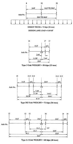
There are several major and minor differences between crane and truck loading on a bridge. For a standard truck load rating, three different types of loads are considered (Figure 1). The first is a design loading and is considered a first-level assessment. This is an HL-93 load per AASHTO LRFD requirements and is outlined in LRFR 6.1.7.1. The second is AASHTO legal loads described in LRFR 6.1.7.2. These include Type 3, Type 3S2 and Type 3-3 vehicular loading and are intended as a second level rating that provides a single safe load capacity for a given truck configuration applicable to AASHTO and State legal loads. The live load factors are based on the truck traffic
By Thomas North, P.E.
Thomas North, P.E. is a structural engineer in the Engineering and Construction Division for the Portland District, U.S. Army Corps of Engineers. Thomas can be reached at thomas.north@usace.army.mil.
conditions at the site. Strength is the primary limit state for load rating, with service limit states being selectively applied. The third type is a permit loading and is outlined in LRFR 6.1.7.3. Permit loading is primarily a check for safety and serviceability for passage of vehicles over a bridge that are above legally established weight limitations. The permit rating should only be applied to bridges having sufficient capacity for AASHTO legal loads. The types of cranes that may see service on a bridge are classified as All Terrain (AT), Rough Terrain (RT), and Crawler (track) cranes. AT or RT cranes will have outriggers for increased capacity that extend between 20-24 feet and may be spaced 20-25 feet apart. Most of these cranes require the addition of counterweights to develop full capacity. The gross vehicle weight (GVW) for a standard design truck is 72,000 lbs. For comparison, an AT crane with a routine or annual permit or an RT crane will have a GVW that varies from 50,000 to 160,000 lbs. The GVW of a crawler crane can vary from 50,000 to 230,000 lbs. AT cranes have a multi axle configuration, a telescoping cantilevered boom and can have a rated capacity of up to 300 tons (Figure 2). The center-to-center wheel spacing can be about 8 feet, with axles typically spaced 5-6 feet apart. These types of cranes combine the road speeds of truck carriers with off road capabilities. They can have features that may include large pick and carry ratings, all axle drive and steering, and can have suspension systems that equalize axle loading on uneven surfaces while the crane is moving or static. Because of their multiple axle configurations, most AT cranes are road legal or may require permits with a specialized boom trailer. RT cranes are two axle carriers with a telescoping cantilevered boom and can have a rated capacity of up to 100 tons (Figure 3). These types of cranes have oversized tires that make travel easier on unimproved construction site roads. The center-to-center wheel spacing can be about 8-9 feet, with axles typically spaced 15 feet apart. Cranes of this type can travel an operating speed of about 30 mph. RT cranes typically have a high center of gravity and are not considered road legal due to higher axle weights. Crawler cranes are propelled by two treads mounted on an extremely stiff base. The tread configurations may be about 17 feet long by 3 feet wide (Figure 4). Each has a separate clutch, brake and lock for independent control of travel and turning. Crawler cranes are not road legal and
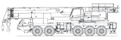
Figure 2: All Terrain (AT) crane.

Figure 3: Rough Terrain (RT) crane.
must be transported with a crawler carrier. Crawler cranes have a lower cost and rental rate than other types of cranes, but their transit costs are higher.
Dynamic Loads
For vehicles, the dynamic load allowance is primarily a function of pavement surface conditions. It is defined in LRFR 6A.4.4.3 and outlines the required impact factor as 33% of the live load. For an approach with minor surface deviations and depressions, it can be adjusted to 20%. For smooth riding surfaces at approaches, deck and expansion joints, the impact factor can be adjusted to 10%. For legal loads, the dynamic load allowance per LRFR 6A.4.5.5 can be applied for permit load rating. This means that for slow moving permit vehicles (10 mph or less), the dynamic load allowance may be eliminated. The live-load factors for permit loads were derived for the possibility of simultaneous presence of non-permit trucks on the bridge when the permit vehicle crosses the span. An adjustment can be made on the live load factor depending on vehicle type and traffic conditions. For permit loads, Table 6A.4.4.2.3a-1 allows an adjustment of live load factors from 1.8 to 1.4 for routine commercial traffic. If traffic can be closed in the opposite lane, Table 4.6.2.2.2b-1 in the LRFD specifications provide specific reductions in live load distribution for single lane loadings of interior beams.
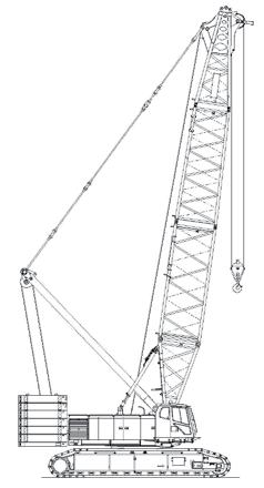
Figure 4: Crawler crane.
Cribbing and Shoring
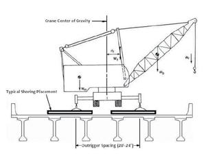
For most instances, cribbing is required to distribute the outrigger loads on the bridge deck (Figure 5). Overloading from improperly placed outriggers can initiate cracking due to general or punching shear failure. Cribbing and shoring can be made from timber, steel or a combination of both with an effective
width “b” and length “c”. Maximum design efficiency can be obtained when b = c; however, the existing bridge geometry, width, girder spacing and type of loading will control the shape of the cribbing. For timber, a check for horizontal shear stress needs to be made. Although the typical practice is to allow some increase in allowable stress for short duration loads, a more rational approach is to forgo these increases because the outrigger loads are calculated without consideration for wind and other dynamic effects. For steel, shear is not as critical condition to check. Cribbing members that are oversized and stiffer will deflect less and provide a more even load distribution; however, the cribbing needs to be checked to verify that members bear uniformly on the base. Filling, leveling or blocking may need to be added.
Loading Near Slopes and Abutments
The effects of surcharge loading need to be taken into account when operating heavy cranes near slopes and abutments. Surcharge loading decreases with added distance; therefore, to determine a safe position for crane set up, a check for stability may be required. If stability is an issue, surcharge loading may be eliminated or resisted with the placement of pontoon shoring on top of the abutment and placement of diagonal shoring along the abutment wall.
The Planning Process
A crane loading plan is needed to assess the loads, establish how the crane will be positioned in place, determine the crane motions and what special equipment will be required. The load information needs to include the combined gross vehicle weight, counterweights, blocks, slings, lifting beams and other lifting accessories. The movement and positioning of a crane on a bridge deck has to be a controlled operation where travel paths have to be predetermined and adhered to. Operating positions and crane motions must be controlled, and all loads, operating radii and horizontal boom angles must be known in advance. The crane motions to be considered are hoisting, swinging, booming (in or out), traveling (if allowed) and sufficient allowance for some deviation in position and maneuvering. A lower risk crane operation employs a minimum of control and control engagements, low motion speeds and durations, as well as shorter boom lengths and picking radii. The crane loading plan should be reviewed and approved by a licensed professional Engineer who is charged with the overall responsibility for bridge-capacity evaluation and has a minimum of five years of bridge design and inspection experience. The following is a sample specification requirement for a crane loading plan on a bridge: 1) Crane Loading Requirements • A loading diagram shall be submitted and approved prior to operating any equipment or vehicles in Figure 5: Typical outrigger & shoring placement. excess of 72,000 lbs GVW and axle loads of 32,000 lbs. • No vehicular traffic will be allowed in • The loading diagram will include, the opposite lane or in the same span but not be limited to, providing that the crane is positioned on. information on the following: • Crane speeds will be limited to 5 mph 1) A typical section and plan view or slower. There will be no sudden of the bridge, the position of the stops or starts. wheel loads and wheel spacing of 2) Shoring Requirements the crane. If using timber, call out the required 2) Crane gross vehicle weight (GVW), grade, Fc, Fb and Fv values. required counter weights and center • If using steel, call out the required of gravity from the axis of rotation. grade and any weldments. 3) Location and weight of axles before • Shoring and blocking must be and after counter weights are accurately aligned as shown on the installed. plan. 4) All outrigger loads. • Crane operations may cause the 5) Required crane boom length, weight shoring to work loose. All wedges, and location of center of gravity. This shims and position of the shoring shall should also include the effects of guy be checked daily. lines, upper spreader and jib mast. • All wedges, shims or fillers must be 6) If using a jib, the length, weight and made of hard wood or steel. No soft location of the center of gravity. wood materials will be allowed. • Prior coordination and approval for such loads shall be obtained before proceeding. No exclusion trucks, Conclusion multi-axle specialized hauling vehicles The response of crane loads on bridges is a (SHV) or mobile cranes will be allowed function of the variability in the age, design, on the bridge deck without prior construction, and condition of the bridge. By review and approval. knowing the differences between vehicular • Any SHVs authorized to drive on the and crane live loads, what the axle configurabridge deck will at all times be required tions are and where the loads are being placed, to have all lift axles lowered and fully the effects of crane loads can be quantified engaged while the vehicle has any load. using a combination of adjustment of live load
For cranes, all specialized boom trailers impact, load factors, load distribution and will be required to be engaged until removal of lane load requirements based on a final set up with the outriggers are Strength II design permit load criteria in the made and approved. AASHTO LRFD and LRFR specifications.▪
ADVERTISEMENT - For Advertiser Information, visit www.STRUCTUREmag.org
Forensic Civil/Structural Engineers
Nelson Architectural Engineers, Inc. (NAE) is seeking to add Licensed Forensic Civil/Structural Engineers to our expert team to perform forensic investigations through fieldwork, and a thorough knowledge of engineering principles. Candidates must possess excellent written and verbal communication skills. Travel is required. Please forward your resume to jwortham@architecturalengineers.com.
Ambassador Bridge Redecking Fosters Growth between Nations
By Michael Borzok, P.E.
As the single busiest land border crossing in North America, the Ambassador Bridge is critical to trade and tourism between the United States and Canada. It is estimated that 150,000 jobs in the region and $13 billion in annual production are reliant on the crossing. As bridge traffic is expected to increase in the coming years, it is important for the region’s economy that the bridge continue to provide for safe and unobstructed traffic flow between the two countries. Motorists traveling on I-75, a major highway that carries traffic through Detroit, could not easily access the bridge from the interstate. The Detroit International Bridge Company (DIBC), the owner of the Ambassador Bridge, and the Michigan Department of Transportation (MDOT) wanted to improve access from I-75 to enable traffic to flow more freely between Detroit and Windsor, Ontario. To do so, they would need to add new ramps to provide direct access from I-75 to the bridge. In order to receive federal funding for the new ramps project and to ensure the safety of motorists crossing the bridge, the MDOT required a complete structural assessment of the existing structure. The effects of decades of heavy use, complicated by the fact that a comprehensive load rating had not been done in a number of years, would need to be assessed. Thus, the Ambassador Bridge Gateway Project was created. The $230 million project is the largest single construction project ever undertaken by MDOT and was created to ensure that the iconic structure will be able to bear the load of future bridge traffic, and serve both the United States and Canada for years to come. The DIBC turned to bridge engineering firm Modjeski and Masters, which had served as design consultant when the Ambassador Bridge was originally constructed in 1929, to lead both the assessment and design phases. Modjeski and Masters began by developing a detailed asset management plan that provided a well-defined strategy for addressing critical needs first and prioritizing others. The plan would ultimately involve an in-depth inspection, and the assessment and instrumentation of numerous members on the bridge. Next, they completed a comprehensive load rating, which identified the need for structural repairs to ensure the safety of the traveling public. Along with the repairs, an internal inspection of the main cables was performed, which included a determination of their strength. Major repairs, as outlined in the comprehensive assessment, were underway in 2007 and included the replacement of 30% of the suspender ropes, the rehabilitation of various structural members and, ultimately, a redecking of the main span. Bridge lanes on the main span also needed to be widened to accommodate 12-foot lanes – today’s industry standard. During the redecking design phase, the engineering team faced a series of challenges that had to be addressed early in the process. Featuring a main span of 1,850 feet, the Ambassador Bridge was once the longest suspension bridge in the world. A suspension bridge of this magnitude, located 150 feet above water level, is a dynamic structure that requires specialized structural expertise during the design phase. Maintaining weight distribution and preventing instability during and after construction were critical to preserving structural integrity and, in turn, motorist safety. A solid Jersey-type barrier presented the first major challenge for the design team. Another consultant, engaged before Modjeski and Masters, had already created deck replacement plans that were ultimately put on hold. As part of their work, however, a solid concrete barrier was specified from end to end. The design team knew a solid barrier could potentially cause a suspension bridge to become unstable during certain wind events. The team engaged an aerodynamic consultant who created a scale model of the bridge that was tested in a wind tunnel, and confirmed that the solid concrete barrier was creating instabilities during strong winds. Working together with the DIBC, it was determined that the concrete barrier would need to be substituted with an open barrier in order to improve aerodynamics. Further complicating bridge behavior was the widening of travel lanes, and the removal of a sidewalk located on only the western side of the bridge. The original bridge had four 11-foot travel lanes – one foot per lane too narrow for today’s safety criteria. Pedestrian and bicycle traffic
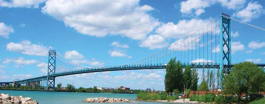
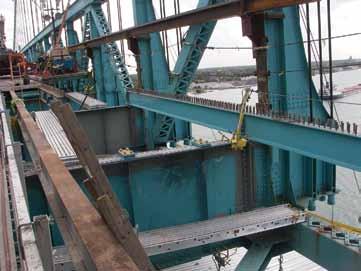
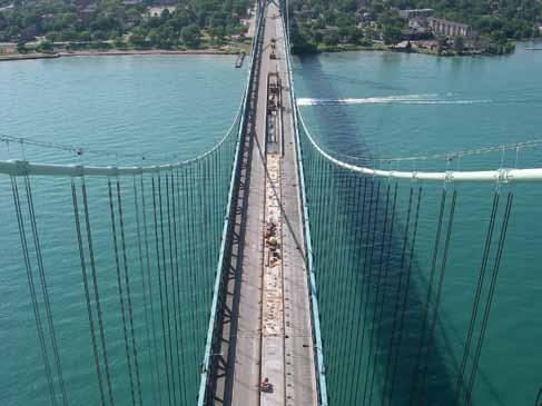
were previously allowed to cross between the United States and Canada, but following the September 11, 2001 terrorist attacks, the U.S. Department of Homeland Security prohibited all pedestrian traffic at international crossings. To accommodate today’s 12-foot lane standard, the design included removing the sidewalk to create more space. However, removing the sidewalk, and replacing it with heavier roadway, presented a new challenge in maintaining bridge balance. To account for the weight imbalance, the design called for the replaced deck to be made up of a combination of lightweight and normal weight concrete. In addition, concrete ballast was added to the westernmost side of the bridge, along with a curb consisting of heavyweight concrete. Another challenge involved traffic flow during the construction stages. Since so much commerce relies on this crossing, it was essential that traffic continue moving throughout the entirety of the redecking contact. The project was broken into four stages, which would allow for three of the four traffic lanes to remain open The rehabilitation of the suspended spans was performed in stages. at all times, as required by the DIBC. Final contract plans were completed in early 2010, and the construc- The deck was removed in 145-foot sections using a gantry crane to tion phase began in June 2010. The construction phase commenced lift and remove each piece. Once the deck was lifted away, construction with the installation of Safespan® decking underneath the bridge. Once teams could remove old stringers and perform repairs to floorbeams, the Safespan® was installed, construction teams began the redecking a majority of which could not be accessed with stringers still in place. process. Active work zones required a temporary concrete safety barrier New stringers were then installed, followed by the placement of new to protect construction teams from bridge traffic. However, at 1,850 steel grid panels, which were then filled with concrete. As noted previfeet in length, a temporary concrete barrier spanning the entire bridge ously, a combination of lightweight, normal weight and heavyweight would once again impact bridge behavior. Redecking would need concrete was used across the four phases to maintain balance and to take place incrementally; to determine the appropriate segment prevent any alterations to the bridge’s geometry. This process was length, a 3D finite element analysis model was created to assist with repeated for each phase of the construction process, with stages one construction staging analysis. Results of the evaluation determined and four requiring the additional step of installing open railings on that 145 feet was a safe maximum length for each section without either side of the bridge. The fourth phase of redecking was finalized impacting the weight distribution of the bridge. Additional weight in May 2012, and construction teams are expected to remain on site corrections were needed as segments of decking and stringers were until the end of the summer to perform clean-up work. removed – steel ballast was used on top of the temporary concrete Not only is the structural health of the Ambassador Bridge critical barrier and was repositioned as new roadway was constructed. to shared commerce between the United State and Canada, but so is using North American products and labor to complete the redecking. The Ambassador Bridge Gateway Project and the redecking of the main span of the Ambassador Bridge are important to growth and rebuilding for the Detroit-Windsor region. With more than 4.6 million passenger cars and 2.6 million truck crossings every year, the rehabilitated 83 year old main span of the Ambassador Bridge can now safely accommodate current traffic and forecasted traffic increases in coming years.▪
Michael Borzok, P.E. is a Senior Project Manager at Modjeski and Masters, Inc., headquartered in Mechanicsburg, PA. Michael can be reached at mjborzok@modjeski.com.
The online version of this article contains detailed references. Please visit www.STRUCTUREmag.org.


The anchor that makes the cut.
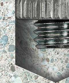
When designing to the latest code provisions that include seismic design categories A through F, you need an anchor that will perform. Our code-listed Torq-Cut™ self-undercutting anchor provides high-load capacity and is a ductile solution in higher-strength concrete. The Torq-Cut anchor is engineered so that pullout is not a failure mode. It is a Category 1 anchor, and designed to resist static, wind and seismic loads in cracked and uncracked normal-weight concrete and sand light-weight concrete. Listed under ESR-2705, the Torq-Cut is evaluated under ICC-ES AC 193 (Acceptance Criteria for Mechanical Anchors in Concrete Elements) and ACI 355.2. For more information, call (800) 999-5099 or visit www.strongtie.com/torqcut.



Cracked& Uncracked
CONCRETE
IBC®
2012
IN THE SPECS ON THE JOB AT YOUR SERVICE™

Collaboration and Innovation Lead to 3 rd Service Life for an Iconic Iron Bridge
By Rich Johnson, P.E. and Steve Olson, Ph.D., P.E.
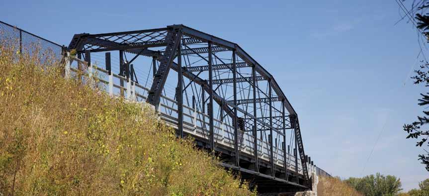
Oblique view.
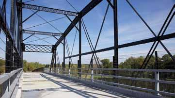
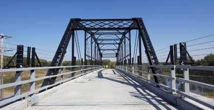
Minnesota was sprouting like a wheat eld in 1877, but the growth could not continue unless improvements were made to the state’s edgling transportation system. One such improvement built that year was a 162-foot Parker truss span in Sauk Centre, MN, located in the central part of the state. Years before the automobile age and the mass production of steel, the bridge enabled horses, wagons, buggies and pedestrians to cross the Sauk River. e bridge was well constructed, with several primary members composed of wrought iron. e inclusion of wrought iron, which stands up to corrosion better than steel, likely played a signi cant role in the long lifespan of the bridge at multiple locations. By the 1930s, the bridge no longer met the needs of the Sauk Centre community, but enterprising Minnesotans found a new use for the span. It was disassembled and in 1937 was re-erected in a wilderness area in northern Minnesota, where it carried State Highway 65 over the Little Fork River in Koochiching County, near the small town of Silverdale. For 70 years, Minnesota Bridge #5721 carried logging trucks and other vehicles at this scenic northern Minnesota location. But as the 21st century dawned, the Silverdale Bridge again faced obsolescence. Besides the fact that the bridge was too narrow for modern highway tra c needs, its badly deteriorated oor system made its load capacity marginal at best. It was time for #5721 to “hit the road” again. In 2009, the bridge was disassembled and stored in a Minnesota Department of Transportation (MnDOT) facility. During the following two years, a collaborative e ort between engineers and historians led to the bridge’s evaluation, rehabilitation and re-erection at a Minnesota Department of Natural Resources (MnDNR) trail near Stillwater, MN, just northeast of the Twin Cities. e bridge not only has been preserved but it has come full circle, once again carrying equestrian and pedestrian tra c. e disassembly, relocation and re-erection project was confronted by signi cant technical hurdles, but those hurdles were overcome through the collaboration of engineers and historians who devised innovative solutions.
A Bridge to Minnesota History
Years before it was dismantled, the Silverdale Bridge was recognized as worthy of historic preservation. In the 1980s and 90s MnDOT, the Minnesota State Historic Preservation O ce (SHPO) and their consultants inventoried the state’s bridges and identi ed those with historic signi cance. Roughly 200 bridges built prior to 1956 were identi ed as either on or eligible for inclusion on the National Register of Historic Places. Among them was the Silverdale Bridge, which was added to the National Register in 1998. In 2006, HNTB Corporation and Mead & Hunt prepared a Management Plan for Historic Bridges in Minnesota under the auspices of MnDOT, SHPO and the Federal Highway Administration. e Silverdale Bridge was one of twenty-four bridges identi ed for preservation by MnDOT. “Maintaining historic properties, including bridges, helps people to understand where they came from – what previous engineers and communities hoped for and what they were able to achieve,” the historic bridge management plan stated. “By protecting these reminders of the state’s engineering and transportation legacy, the present and the future can be built, since their preservation can save valuable tax-payer dollars and recall a community’s hopes and dreams.”
Formulating a Strategy
Based on the goals of the historic bridge management plan, engineers and historians worked together to develop a preservation strategy for the bridge. Team members determined that widening
and strengthening the bridge for continued use at the Silverdale site would require dramatic changes to the bridge, including a substantial loss of historic material and alteration of character-defining features. The team ultimately decided the course of action would be to move the bridge to a new site with less demanding expectations on the venerable structure. MnDOT worked with MnDNR to identify the most appropriate site. The stakeholders zeroed in on the Gateway Trail, the most heavily used DNR trail in Minnesota. As part of an abandoned railroad corridor that has been converted to trail use, the Gateway Trail traverses several at-grade crossings with heavily traveled roadways. The team identified an at-grade crossing with sight distance challenges near Stillwater that made it a good candidate for a grade separation bridge.
Laser Scanning Gathers Crucial Data
While the premise of the bridge relocation project was sound, its execution was no easy task. For example, plans related to the 1870s bridge construction had vanished into history, and only a handful of sheets were available from the 1930s disassembly and re-erection. To overcome the lack of crucial information, the consultant team decided to use laser scanning of the bridge to collect geometric data prior to disassembly and as major components were removed. This technique, which employs a terrestrial laser-imaging system that creates highly accurate three-dimensional images, proved to be extremely useful. Fastener patterns taken from the scans of original portal members and end floor beams were used to detail replacement members. In addition, the scan data facilitated the capacity evaluation of the eyebars that had suffered defects during removal operations. The information gleaned from this geometric evaluation enabled 88 of the 96 original wrought iron eyebars to be incorporated into the bridge at its third location.
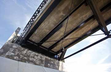
Below deck, stringers, sway bracing at abutment. A Bigger Job Than Anticipated
Extensive rehabilitation was required before Bridge #5721 could be moved to its new home. The re-assembly contractor carefully removed the iron truss components and transported them to White Oak Metals Inc., a steel fabricator in west central Minnesota. There the components were blast cleaned and revived. After blast cleaning, it was apparent that many of the primary truss eyebars had been damaged during disassembly, despite the great care taken by the construction contractor. The disassembly contractor’s hardened tools produced nicks and gouges in the heads of the eyebars as the pinned connections were taken apart. Damage to a floor beam and to several upper chord members also was noted once the members were blast cleaned. The need for replacement end floor beams, replacement portal members and replacement stringers was expected from the start. But the need to replace 8 of the 96 primary eyebars, as well as the need to fix an interior floor beam and several top chord members, had not been anticipated when the re-assembly contract was let.
New Technologies Boost Old Components
As design work progressed, it became clear that the truss span would lack the capacity to carry full pedestrian loads and a normal weight concrete deck once the bridge was relocated to the Gateway Trail site. To minimize the need to strengthen the primary truss members of the historic structure, the designers decided to use an innovative lightweight concrete deck (110 pcf). This innovation constituted one of the most significant aspects of the new design. This approach was not a typical MnDOT practice, and it is believed that only one other bridge deck of this type has been constructed in Minnesota. The contractor’s initial lightweight mix design did not meet freeze-thaw durability testing requirements, but a revised mix design passed the tests.
Collaboration Produced Another Innovative Solution
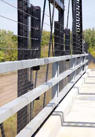
Designing the bridge railing for the new site posed yet another significant challenge for the design team: meeting safety concerns while minimizing visual changes to the historic structure. To meet the challenge, engineers and historians collaborated to devise this solution: Three horizontal rails from the second bridge site were re-used at the third site. The top re-used rail was set at 54 inches, which is the typical
Project Participants
Owner: MnDOT (legacy), MnDNR (present) Designer: HNTB/Olson Nesvold Engineers Cultural Resource: Mead & Hunt Contractor: Minnowa Construction Software: STAAD III and Lusas (analysis) Cloudworx by Leica (laserscanning data)
Portal frame.
height of bicycle railings in Minnesota. The other two rails were evenly spaced below the top rail and the curb, much as they were at the second site. A stainless steel mesh was placed behind the rails to limit the potential for debris to reach the roadway below the bridge. Above the top rail, stainless steel marine cables were installed on a 6-inch spacing to provide an 84-inch tall railing for equestrian trail users. The marine cables and stainless steel mesh greatly enhanced the safety of the bridge and, since they imposed very little visual impact on the railing, it retains much the same look that greeted users of the bridge at its second location.
Great Team Produced Great Results
This project enabled Minnesota to sustainably re-use a state asset and preserve a historical segment of the state’s infrastructure, for the benefit of residents and visitors. The project faced significant challenges, and it could not have attained success without the hard work, creativity and collaborative spirit of the project engineers and historians. The positive results of their efforts demonstrate the high level of innovation that can be achieved through the collaboration of dedicated experts from different fields.▪ Rich Johnson, P.E. is Group Director of Seattle Office Bridges and Tunnels at HNTB Corporation. He can be reached at rjohnson@hntb.com. Steven A. Olson, Ph.D., P.E. is president of Olson & Nesvold Engineers, P.S.C. He can be reached at steve.olson@one-mn.com.

TAY24253 BraceYrslfStrctrMag.qxd 9/3/09 10:09 AM Page 1
YOU BUILD IT. WE’LL PROTECT IT.
SEISMIC PROTECTION FROM TAYLOR DEVICES
Stand firm. Don’t settle for less than the seismic protection of Taylor Fluid Viscous Dampers. As a world leader in the science of shock isolation, we are the team you want between your structureand the undeniable forces ofnature. Others agree. Taylor Fluid Viscous Dampers are currently providing earthquake, wind, and motion protection on more than 240 buildings and bridges. From the historic Los Angeles City Hall to Mexico’s Torre Mayor and the new Shin-Yokohama High-speed Train Station in Japan, owners, architects, engineers, and contractors trust the proven technology of Taylor Devices’ Fluid Viscous Dampers.
Taylor Devices’ Fluid Viscous Dampers give you the seismic protection you need and the architectural freedom you want.
www.taylordevices.com
North Tonawanda, NY 14120-0748 Phone: 716.694.0800 • Fax: 716.695.6015
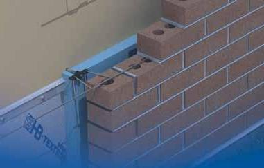
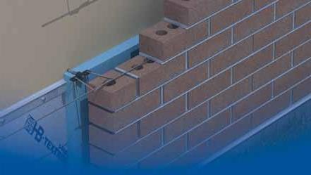
HOHMANN & BARNARD Thermal 2-Seal™ Wing nuT


Reduces Thermal Transfer Through Rigid Insulation


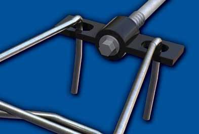
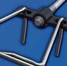
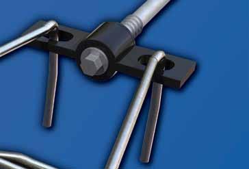
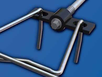
The wing portion of this innovative single screw veneer anchor is fabricated from a highly flame resistant, UL-94 plastic which creates a thermal break. This decreases the transfer of thermal energy through rigid insulation or wallboard.
FEATURES:
.Stainless Steel dual-diameter barrel with Polymer Coated screw . Factory installed ePDM washers seal both the insulation and the air/vapor barrier . Wings are adjustable up to 1/2” to create a water tight seal and prevent moisture infiltration with various insulation and wallboard combinations
.Made with a 5/16” hex head to easily install with a standard hex socket
.Plastic wings are factory installed so there is no fumbling with clips on the job site . available in 5/8”, 1”,1-1/2”, 2”, 2-1/2”, 3”, 3-1/2”, 4” and 4-1/2” lengths to accommodate various insulation and wallboard thickness
.Install with SH - Seismic Hook and Continuous
Wire as shown for use in seismic zones
Thermal Concrete 2-Seal™ Wing Nut for wood and concrete applications also available
U.S. PaTeNT #7,415,803


