12 minute read
Structural Practices
practical knowledge beyond the textbook This is the second of a two-part series examining the engineering and design of strawbale buildings. The first part, September 2012 issue of STRUCTURE, provided an overview of the structural system and best practices for the design and detailing of strawbale walls to resist in-plane lateral loads. Part 2 addresses out-of-plane response, resistance to uplift, and support of gravity loads.
In-plane and Out-of-plane Behavior
Part 1 of this article showed that, for in-plane loading, plaster skins on strawbale walls act as cantilevered vertical rectangular sections braced by the straw bales. This differs from light-framed wood shear panels, which can be idealized as cantilevered elongated I-sections with posts and hold-downs where the shear panels act as webs and the hold-down posts act as vertical flanges. For straw bale walls spanning vertically subjected to out-of-plane loading, the straw bales act as webs between the plaster flanges to form composite I-sections, unlike the case of wood-framed walls where the rectangular section wood studs span vertically to supports. Under uniform Strawbale Construction out-of-plane loading, a constant bending stress is maintained for strawbale Part 2: Out-of-plane, walls if the ratio H/T0.5 is held constant, instead of the more common Uplift and Gravity H/T for rectangular studs or solid walls, where Behavior and Design H is the strawbale wall height, and T is the wall thickness T. This is because bending moment is By Kevin Donahue, P.E., S.E., Martin Hammer, Architect and Mark Aschheim P.E. a function of H2 for all uniformly loaded walls, but section modulus is a function of T for strawbale walls with their I-sections instead of T2 for rectangular studs or solid walls. So increasing the out-of-plane aspect ratio by reducing T has Kevin Donahue, Structural a smaller effect on out-of-plane bending stress as Engineer, and Martin Hammer, compared with a typical rectangular or solid wall. Architect, have practices in This is reflected in the H/T0.5 slenderness factors Berkeley, California. Mark in the current IBC strawbale code proposal. In Aschheim is Professor and contrast, increasing the strawbale in-plane aspect Chair of the Department ratio by reducing wall length L has a greater effect of Civil Engineering at Santa on strawbale in-plane bending stress than for a Clara University. typical cantilever I-section type shear wall, such as a wood panel wall with hold-downs. This is reflected in the penalty for in-plane aspect ratios greater than 1:1 in the current IBC strawbale code proposal. Although the behavior models of strawbale walls and light wood-framed walls are quite different,
An expanded version of this article, including references, is available online at www.STRUCTUREmag.org. The proposed code provisions along with an archive of important tests, research results and analyses of system behavior are available at www.ecobuildnetwork.org. the stiffnesses of strawbale walls and wood-framed walls are well matched. The in-plane stiffness of a typical hard-skin strawbale wall is about onethird greater than a typical wood shear panel wall, and the in-plane stiffness of a typical soft-skin wall is about one-third less than a wood shear panel wall. For out-of-plane loads, the stiffness of either a hard-skin or soft-skin wall is generally in between that of a 2x4 stud wall and a 2x6 stud wall. Because of this, strawbale walls are very well suited for use in flexible diaphragm and wood shear wall buildings, and none of the special detailing of concrete or masonry walls in wood construction is required.
While resistance to superimposed vertical and in-plane lateral loads is provided by designated structural components, every wall must be able to resist out-of-plane forces. As presented above, strawbale walls achieve this through composite action between the plaster and mesh “flanges” and the strawbale “web.” Because the plaster flanges are much stiffer than the strawbale core, if a composite section is modeled as an I-section, the transformed web is very thin. Therefore, shear deformation of the straw bale core has a much larger contribution to out-of-plane strawbale wall deflection than in other typical wall systems for which flexural deformation is dominant. Under a uniform out-of-plane load w, the mid-height deflection due to shear deformation of the straw web (wH2/8G(straw)A(straw)) of a soft-plaster wall is somewhat larger than the mid-height deflection due to flexure (5wH4/384E(plaster) I(overall-section)). For a hard plaster wall, the stiffness of the skin relative to the extreme flexibility of the straw web causes the shear deflection term to dominate and flexural deflection term to become negligible. The dominance of shear deformation in the out-of-plane behavior of hard plaster walls results in virtually all deformation taking place in the straw webs, which deform as nearly perfect shear parallelograms, and almost no deformation taking place in the plaster flanges, which tend to remain rectangular. However, the hard skins themselves initially form a secondary system to resist out-ofplane load by bending as tall thin panels, until they crack in bending near mid-height. The midheight crack causes a loss in stiffness, at which point the skins form rectangular sections between the cracks and supports (Figure 1). This secondary system generally takes about twenty percent of the load, but in an extreme case (for example, if the hard skins are two-inches thick and the straw bales are fifteen-inches thick), the secondary system can take eighty percent of the load before cracking. Such a wall was tested in Mill Valley, CA in 2001, with the measured results matching the model (Figure 2). The tested wall showed the high initial stiffness associated with the intact secondary system, followed by a loss of stiffness upon mid-height cracking, confirming the secondary bending of the skins. The flexural
Figure 1: Model for post-cracking wall behavior.
crack in the tension face plaster of the Mill Valley wall clearly shows bending in the skin (Figure 3). Subsequent test results consistently correspond to these models, and have demonstrated that properly detailed soft or hard skin walls are able to resist outof-plane loads well over 100 psf. For high load conditions, given the composite section model, the engineer can easily isolate and check individual components of the out-of-plane system for strength. Typical load conditions are addressed in the design parameters section below.
Behavior of Walls Subjected to Uplift Loading
The capacity of plastered strawbale walls to carry uplift and gravity loads depends on the capacity of the plaster skins to carry axial force. As discussed, both the in-plane and out-of-plane models rely on the skins taking axial force, so an understanding of tensile and compressive capacity of the skins in uplift and gravity loading is also applicable to the in-plane and out-of-plane models. For uplift, testing shows that a soft plaster reinforced with 2 inch by 2 inch high-density polypropylene mesh, the weakest combination of plaster and mesh included in the IBC strawbale code proposal, carries a tensile force of 400 pounds per foot at out-of-plane yielding. Component testing shows the mesh itself has an ultimate tensile strength of 450 pounds per foot. Therefore, an allowable tensile load of 200 pounds per lineal foot for any recognized reinforced skin is reasonable, and easily supported by the minimum proposed spacing of staples at top and bottom boundaries of 2 inches on center (since a 16-gauge staple has an allowable shear value of 55 pounds). Considering both skins together, the allowable tensile load would be 400 pounds per lineal foot, which would be an unusual loading, likely occurring only in a high-wind region and requiring special design and detailing to ensure proper anchorage.
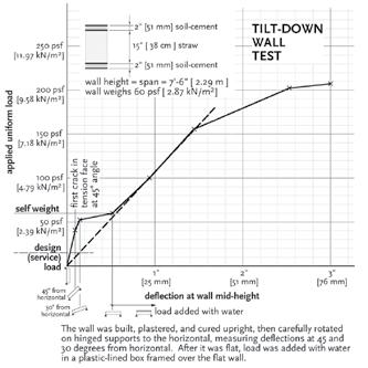
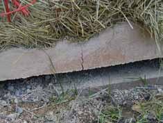
Figure 3: Flexural crack in plaster tension face of test wall laid flat with applied load above.
Behavior of Walls Subjected to Gravity Loading
Load-bearing strawbale walls support superimposed gravity loads by engaging the plaster skins in compression using properly detailed load paths. Nonload-bearing walls support their self-weight and may be used as infill in post-and-beam frames, either within the strawbale core or bordering the wall. The frames are designed to carry gravity loads and possibly uplift loads. Uplift loads are typically carried by the plaster reinforcement acting in tension, while gravity loads are carried by the plaster acting in compression. Buckling of the plaster skins must be considered where compression is carried: local buckling of an unbraced portion of skin or, where the skin is adequately braced by the straw, global buckling of the entire wall. In the case of global buckling, the critical Euler buckling load depends on the balanced relationship between the flexure and curvature produced by axial force acting through a small lateral displacement (“P-delta”), and the moment of inertia “I”, which is the global flexural stiffness of the wall
Plaster Type
Plaster Thickness (inches) Baseline Plaster Material Strength (psi) Vertical Wall Strength (plf) Factor of Safety
Proposed Allowable Gravity Load (plf) Clay 1.5 100 3600 9 400 Soil-cement 1 1000 24,000 30 800 Lime 7/8 600 12,600 25 500 Cement-lime 7/8 1000 21,000 26 800 Cement 7/8 1400 29,400 37 800
section in the out-of-plane direction. There is no such feedback interaction between the vertical P-delta and shear deformation in the out-of-plane direction. Since strawbale walls tend to be quite flexible in out-of-plane shear but quite stiff in out-of-plane flexure, the critical buckling load π2EI/H2 is very high, over 10,000 pounds for a typical eight foot tall soft-skin wall and over 1,000,000 pounds for a typical eight foot tall hard-skin wall. Tests of plastered walls with superimposed gravity loading confirm that both local skin buckling and global buckling of the wall are not observed modes of failure. These tests, along with out-of-plane tests, show that the bond between plaster skins and the strawbale core is adequate to allow the bale core to brace the plaster skins and act as a web in the plaster-bale assembly. Observed failure modes in gravity tests of plastered walls are crushing of the plaster skin or failure at the top or bottom plaster boundaries. For this reason, best practices described in subsequent sections for load-bearing and shear walls call for continuous support along the bottom edge of the plaster skins. For loadbearing walls, direct bearing at the top edge is preferred. However, load transfer through properly designed mechanical fasteners is acceptable for gravity load and necessary in the case of uplift.
Design Parameters
To limit stresses in reinforced hard-skin plasters under out-of-plane loading, the unsupported height of walls with hardskin plasters is limited to 9T0.5 feet for a 40 psf out-of-plane service load, where T is the strawbale core thickness in feet. This limit corresponds to service tensile and compressive forces in hard-skin chords of 400 pounds per foot. Tests demonstrate that a hard plaster reinforced with steel mesh carries a tensile force of 600 pounds per foot at out-of-plane yielding, and develops an ultimate tensile strength of at least 960 pounds per foot. Component testing shows the mesh itself has an ultimate tensile strength of 1960 pounds per foot, indicating that the failure mode of the reinforced plaster is something other than failure of the mesh in tension. Unsupported height of walls with soft-skin plasters is limited to 8T0.5 feet for a 30 psf out-ofplane service load. This corresponds to a service tensile and compressive force in the soft-skin chords of 244 pounds per foot. Tests demonstrate that a reinforced softskin carries a tensile force of 400 pounds per foot at out-of-plane yielding, and develops an ultimate tensile strength of at least 640 pounds per foot. Component testing shows the plastic mesh alone has an ultimate tensile strength of 450 pounds per foot, indicating that the failure mode in the soft-skin case is a combination of the mesh and plaster acting together to supply the required tension. Compressive skin stresses in all cases are well under tested capacities, and both tested and calculated service load deflections are less than allowable limits of H/180 for hard-skin walls and H/120 for soft-skin walls. Out-of-plane testing consistently shows failure occurring in the body of the strawbale assembly near mid-height, and not at the top and bottom supports, but design parameters establish a minimum stapling of the plaster mesh at top and bottom boundaries to ensure adequate out-of-plane support of all walls. For walls up to 10 feet in height, staple spacing of 6 inches, top and bottom, provides adequate resistance for out-of-plane loading of 30 psf based on the allowable withdrawal values in the 2012 IBC for the staples specified in the IBC strawbale code proposal. For walls taller than ten feet or with out-of-plane loading greater than 30 psf, the maximum staple spacing is reduced to 4 inches. Hard-skin walls with service loads greater than 40 psf, soft-skin walls with service loads greater than 30 psf, or walls exceeding the height limits stated in the IBC proposal require a design addressing critical sections. A seven-step methodology for checking such highly loaded walls is presented on pages 96-101 of Design of Straw Bale Buildings by Bruce King, et al (2006). For uplift loading, each skin with a recognized stapled mesh is given an allowable tensile value of 200 pounds per foot. For uplift loads exceeding this value, a detailed design is required similar to that required of walls with high out-of-plane loading. In all cases, uplift forces above the top stapled skin boundary must be designed with a conventional code-compliant load path to the skin boundary. Proposed allowable gravity loads for plastered strawbale walls are provided in the Table. Height limits ensure that crushing of the plaster governs over buckling. Allowable gravity loads are then established from the baseline strengths of the recognized plasters. The results of testing coupled with conservative factors-of-safety (particularly for hard-skin walls) provide confidence that local buckling of the skins will not occur. The Table values are also conservative and consistent with results from gravity tests of full-scale walls. Bottom edges of all plaster skins are continuously supported, and applied loads are transferred to the top edges of plaster skins by continuous direct bearing or through mechanical fasteners.
Concluding Remarks
Collective understanding of the structural behavior of strawbale wall systems has increased enormously since the days when pioneers built the first load-bearing strawbale houses in the Sand Hills of Nebraska over 130 years ago. The essence of those first walls – bales stacked on a foundation, covered with plaster, with openings for doors and windows – remains in the many variations of straw bale wall systems now employed throughout the world. Significant differences exist as well. While the original buildings were load-bearing, most strawbale buildings today are post and beam with strawbale infill. Today’s buildings are often significantly larger than the early buildings and sometimes are two stories. Substantial advances in the understanding of strawbale wall behavior have occurred through the testing, research and practice of architects, engineers, and researchers, who have focused on this inherently green material of construction. A sufficient basis now exists for the design of strawbale walls to meet modern performance expectations.▪


