
PORTFOLIOPORTFOLIOMINGJIASHIBACHELOROFDESIGNMASTEROFARCHITECTURE2018-2022

CONTENT 01 - GARDEN OF EARTHLY DELIGHTS URBAN INTERVENTION - BEE FACTORY|GROUP WORK Barcelona, Spain |Systematic project 02 - NEBBIA ADAPTABLE SYSTEM|INDIVIDUAL WORK Non site experimental inhabitation |400 m2 Occupy Area 03 - ECOTONE RESIDENTIAL REGION - COHOUSING|INDIVIDUAL WORK The corner of High Street and Walker Street in Northcote, Melbourne |10100 m2 Occupy Area 04 - FROST TOWER OFFICIAL AND RESIDENTIAL TOWER COMPLEX|GROUP WORK Between Lonsdale Street and Little Lonsdale Street, Melbourne |93018 m2 GFA 05 - OTHER WORKS PARAMETRIC DESIGN / CONSTRUCTION PHYSICAL MODEL
URBAN INTERVENTION - BEE FACTORY|GROUP WORK
GARDEN OF EARTHLY DELIGHTS
BARCELONA, SPAIN |SYSTEMATIC PROJECT Industry is a program which always be regarded as harmful to the urban environment. However, when industry endowed with biological features, will it intervene urban posi tively? This project tries to introduce urban with the bee’s living mode as superorganism which is a high resilience social mode. If the city could behave as a superorganism, each individual functions just setting to fulfil earthly delights of citizens, will it brings factory back as a positive perturbance?


No matter how it reinterprets itself, we come up with a future vision led by machine to achieve a resilient, reflective, and responsive urban system. If from the beginning, the god gives us the garden of earthly delights, the machine will help the current Anthropocene to find a new gar den of earthly delights which is suit for now and ready for the future.

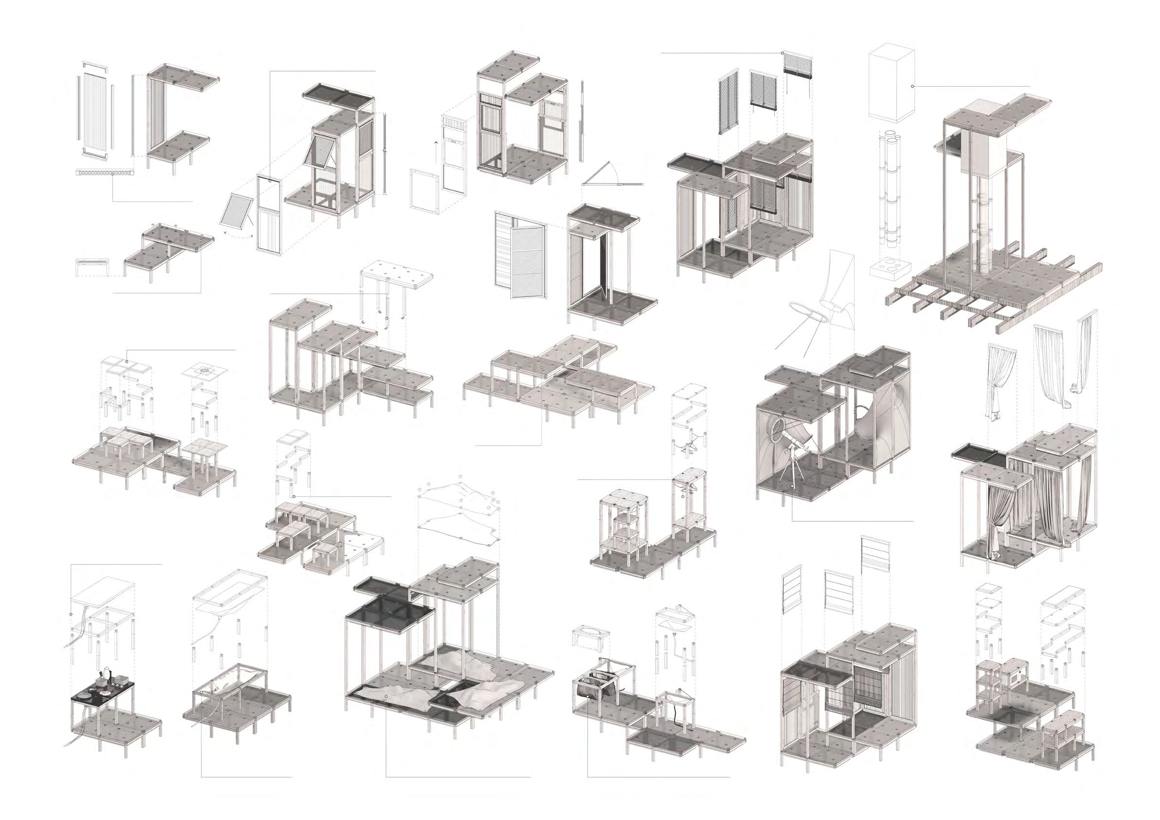
WORK Non site experimental inhabitation |400 m2 Occupy Area The project aims to establish a surrealist world where each expression of personal humani ty will have recreation via the government’s rationing system. Here, permanence means death. Here, irreversible is out of control. Here, spirituality is higher than substantial. Here, no surrender, no succumb, no classes.
ADAPTABLENEBBIASYSTEM|INDIVIDUAL

Flipping window and sliding window. Steel angle fix only appear when column is higher than 1200mm.
Ceramics bathtub is replaced with operable membrane. Preventing indirect expression of function. Everything return to fundamental requirement and satisfy. Kitchen sink also use membrane to replace steel sink.
Platform module could become chair and table. Wardrobe with different size and height is modular. Self expression membrane provided to people with different living aspirations. Different sizes of setting and bench available. Joint applied on the platform. Tenon seeks applied for its reversibility. Induction cooker assembled with tenon seeks.
Polycarbonate as insulation.
The entire building provided with translu cent enclosure. Here service is part of the flexible system which can adapt different space easily.
Communal agricultural system follows the circulation through the communal space. Material fabrication communal space: people take raw material from the bank then fabricate into tenon seeks follow the instructions. • Single unit × 5 - 1person/unit • Couples without children × 5 2 TOTALpeople/unitAREA = 48.64m² Level 1 = 20.48m² Level 2 = 28.16m² Twin unit × 2 2 people/unit Single parent family × 3 people/unit2~3 • Nuclear family × 4- 3~4 people/unit TOTAL AREA = 78.72m² Level 1 = 34.56m² Level 2 = 44.16m² • Extended family × 4 - 5~6 TOTALpeople/unitAREA = 104.96m² Level 1 = 47.36m² Level 2 = 57.6m² • Group living type A × 1 - 10 people/unit 7 TOTALBedroomsAREA = 168.96m² Level 1 = 76.8m² Level 2 = 92.16m² Level 1 = 20.48m² Level 2 = 28.16m² Level 1 = 47.36m² Level 1 = 57.6m² Level 2 = 92.16m² Level 1 = 92.16m² Level 1 = 76.8m² Level 1 = 104.96m² Level 1 = 34.56m² Level 2 = 44.16m² Fire proof membrane tunnel only appears in the evacuation stair case surrounding the core lift. Material bank stores the required raw material, modular slab unit, curtain with different translucent levels for people toBackrent.up space for damaged module stock for repairing. Bicycle parking and car parking area applied on each side of the entrance corner. GROUND LEVEL LEVEL 3 LEVEL 2 LEVEL 4 Occupants on site could sell agricultur al stuff and fabrications to tourists. Group living could be easily combined and detached due to dynamic situations. Galvanized perforated metal used as com munal material.circulation 4000 8003 200 80024004000 800 320400300300 200 4000400 3200 80 3200 4000 3200 80 0 40002400 160 300 300 3200 1600 2400 200 300 300 3200 1600 2400 20 3200 800 2400160320 3200 80

Timber truss applied to support long canti lever of BMU which reaches the edge. Fire proof membrane applied as evacuationtunnel.
When facing to the unit entrance, the mem brane scrolled up as openings. Original status: weather.ordinary Hydraulic vertical garden lift allow vegetations move vertically. Moist weather: rainy, cloudy days. Dry weather: sunny, windy, cold dry days.
BMU applied for construction and mainte nance purpose.
BMU track applied 2 directions to allow 2 BMU could cover the entire building scope.
Communal agriculture facility unit could be applied as enclosure sun shading. It is assembled by flexible timber structure, thus could be adjusted the location depend on Theseason.building encourage people to express their personalities through the space and has the ability to express emotional change of Nopeople.internal solid wall, everything is neutral with further defined by occupants. Agriculture facility module could be added on roof garden on individual platform, and could also applied on the enclosure structure as shading to protect building inner environment. Unit can be dissolved and merged through adding or deleting the modular platform.
Roof garden use the same material with the communal agriculture facilities - timber column, water proof fabric bag for soil Galvanizedcontainer. Perforated circulation path and staircase applied through the vacancy among units. Still applied as modular units, thus could be easily remapped.

Pulley system applied with smaller platforms for storing goods. Bicycle parking applied on both side on the north east corner.
Material platform.fabricatedToilet, bathroom Kitchen
Following the primary struc ture, water distributed to each detached clusters. Timber joist structure applied on the ground floor to lift the ground level above the ground. Timber decking cover ing on top of the joists. Hydraulic material bank lift applied for material storage. Universal beam applied with diagonally cut.
Vertical sliding track fixed on the outer layer of the primary structure.Moisture sensitive material applied on the enclosure to prevent weathering.
Hydraulic car lift applied with 8 places which could deliver cars horizontally and vertically.Primary extended under ground to generate timber posts as the foundation Staircasestructure. applied to adapt differ ent landscape situations. Water directly support the individual service cluster from the bottom, then drained away separately.
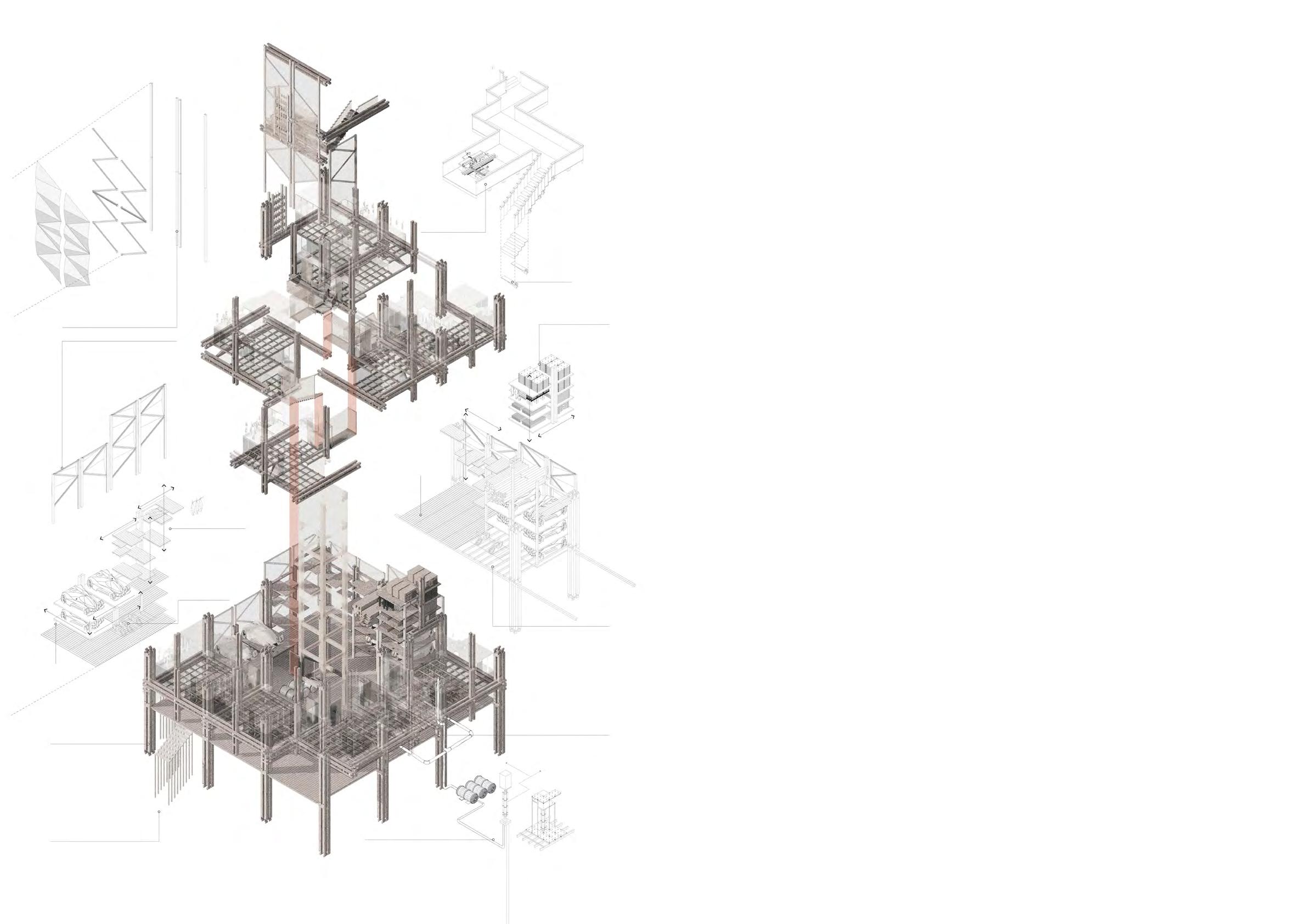

E C O T O N E RESIDENTIAL REGION - COHOUSING|INDIVIDUAL TheWORKcorner of High Street and Walker Street in Northcote, Melbourne |10100 m2 Occupy Area Ecotone is the interactive balance of communities Co-living. One community change, the Ecotone, transforms into a new adaptive form. As a project that aims to transcend the constraints of inten sive residential architecture, intrinsically limited spatial atmospheres, and scope of change, this project seeks to use an ecological per spective to explain the possibility of future residential architecture. What is the present, what is the future? If architecture can find it’s way to adapt into different ages, into different occupier? Please click image to see the video for this project: https://youtu.be/eoPiBbFwUvE


In-site Pubic Space Visual Link Acitve Space Curbside Gallery & Art Rental Space Bicycle Parking & Connec tion With Other Island Material Supply & Maintenance Stop Communal Bath Bottom Gallery Garden (Self Define)Greenhouse & Retail Platform Curside Retail Space Circulation Elevating Direction Communal Bath Bottom Gallery Garden (Self Define) Private Residential Space Direction Structure Stage1 Garden Platform Basic Wall Provided Stage2 - Communal Functional Platform Self Define Structue Stage3 - Residential Platform In-island Communal Elevated Platform Material Supply & Maintenance Stop In-site Private Communal Space Out-island Private Com munal Out-islandSpacePublic Com munal CirculationSpace Circulation ECOTONE 1 INTRODUCTION ZONE ECOTONE 2 TRANSITION ZONE ECOTONE 3 ISLAND LIVING SPHERE

Overall Plan and Seciton

Detialed Ecotone 1 Section


Between Lonsdale Street and Little Lonsdale Street, Melbourne |93018 m2 GFA
The project aims to design an office and dwelling complex tower to serve both working and living. The Frost tower emphasises a transition from the ground historical architecture to the upper Melbourne skyline, the modern glazing facade. The concrete window shad ing gradually disappears when it gets higher to express the new growth of Melbourne from history to the future.
OFFICIAL AND RESIDENTIAL TOWER COMPLEX|GROUP WORK (3P)
FROST TOWER

The base part is the office block. The triangular cuts on the edges are designed to minimize the influence of wind, as well as provide view through the transparent facade. The hotel on the top part is risen to form a gap, which became the sky lobby. Inside the cut edge are some dou ble-high spaces, where lounges and other facilities are located at.
Low-rise office lift: 6 lifts Start from the ground floor and end on the top level of the low-rise office (L20). The high-rise hotel lift and crown lift would continue use the lift shaft on the upper level, but the shaft would change into function room on the levels in-between.
Medium-rise office lift: 4 lifts Serve as the direct transpor tation to deliver people from ground to medium. Thus, it is not open on the low-rise office levels (L1-L19), but open on L20 to allow low-rise lifts exchange to medium-rise lifts. It would end on L33 to make sure the security level of the upper hotel. On L33, people could exchange to sky lobby lift to achieve hotel sky lobby. Sky lobby lift: 3 lifts To ensure the security level of the high-rise hotel, the sky lobby lift only opens on the ground floor, top medi um-rise office floor (L33) and sky lobby.
Crown lift: 2 lifts Only open on the sky lobby and crown to introduce pub lic into the crown restaurant and sky garden to active the crown’s function. Goods & fire lift: 2 lifts Serve as the supporting sys tem of supplement and entire rescue, go through the entire building and open on each level, but stop on the crown first Level-L51.
The podium reacts to the different conditions of site. The chamfered corners are set back, acting as main entrances for office and hotel separately.
High-rise hotel lift: 4 lifts Start from sky lobby, these 6 lifts only supply the hotel transportation to make sure the protection of guests.
Pedestrian access & circulation Vehicle access & circulation SITE PLAN Dimension of site plan CorePodiumlayoutLift layout Medium-rise office Podium Low-rise Medium-rise High-rise Mechanical floor Skylobby High-rise hotel Building Arrangment Analysis Mechanical floor Skylobby Overall floor plate Ground floor Low-rise office

CROWN GFA: 4035m2 Module: 1500mm×1500mm Structure configuration: Concrete Megastructure with outrigger. SL1 - PT concrete slab, 250mm thick SL2 - PT concrete slab, 200mm thick BB1 - PT band beam (primary), Depth: 600mm, Width: 2400mm BB2 - PT band beam (typical), Depth: 400mm, Width: 2400mm BB3 - PT band beam (corners), Depth: 400mm, Width: 1200mm EB1 PT concrete beam (edges), Depth: 600mm, Width: 1050mm SL1 PT concrete slab, 250mm thick SL2 PT concrete slab, 200mm thick Corner Column, 900mm Corner Column, 900mm Corner Column, 900mm BB1 - PT band beam (primary), Depth: 600mm, Width: 2400mm BB2 - PT band beam (typical), Depth: 400mm, Width: 2400mm BB2 - PT band beam (typical), Depth: 400mm, Width: 2400mm EB1 - PT concrete beam (edges), Depth: 600mm, Width: 1050mm 530OutriggerUB92 (209mm*533mm) 530OutriggerUB92 (209mm*533mm) Structural Beam 610 UB 125 (229mm*612mm) Edge Beams Steel hollow 600mm500Crown380mm*100mmsectionColumnWC440(500mm*480mm)CoreWallThickness,lvlG-lvl 21 450mm Core Wall Thickness, lvl22 - lvl 35 270mm Core Wall Thickness, lvl36 - lvl 51 Overall Section Belt Truss 530 UB 92 (209mm*533mm) Belt Truss 530 UB 92 (209mm*533mm) Rail of Building maintenance unit Mega 2100mmColumnlvlG - lvl 21 1500mm lvl 22 - lvl 35 900mm lvl 36 - lvl 51 Mega 2100mmColumnlvlG - lvl 21 1500mm lvl 22 - lvl 35 900mm lvl 36 - lvl 51 Mega 2100mmColumnlvlG - lvl 21 1500mm lvl 22 - lvl 35 900mm lvl 36 - lvl 51 Side 700mmColumnlvlG - lvl 21 600mm lvl 22 - lvl 35 500mm lvl 36 - lvl 51 Side 700mmColumnlvlG lvl 21 600mm lvl 22 - lvl 35 500mm lvl 36 - lvl 51 Side 700mmColumnlvlG lvl 21 600mm lvl 22 - lvl 35 500mm lvl 36 - lvl 51 MECHANICAL ROOM GFA: 1645m2 HOTEL 14 NLA:GFA:LEVELS23365m218829m2 MECHANICAL ROOM GFA: 1689m2 MEDIUM RISE OFFICE 12 NLA:GFA:LEVELS27019m221835m2 MECHANICAL ROOM GFA: 1675m2 LOW RISE OFFICE 16 NLA:GFA:LEVELS19840m215952m2 MECHANICAL ROOM GFA: 1620m2 PODIUM 4 GFA:LEVELS12084m2 CAR PARKING GFA: 10800m2 HOTEL LOBBY GFA: 1686m2 NLA: 1362m2

Steel stud front view Downpipes to tower connection & concrete stud
StrandrodStructuralCable Sta-Lok’s stain less steelcouplercross
Partial -
Plastic glass joint Spider fitting Coupler
Connection plate
Clear Laminated PVB glass panels with low-e coated.
Cable truss fixing exploded isometric
Space frame tube plate Provid ed by Safsteelstructure. Space frame tube Provided by Safsteelstructure.
CableCirclipstruss fork Skyguard hail gutter guard system
Extruded gutter
The lowest point of the hanging curtain wall is 4.5m above the ground to protect people from weathering on the path way.
Partial elevation - podium east entrance
Steel hollow section con nected together to form the gutter system and act as the frame of roof glazing. Steel side stud A pair of 150UB univer sal steel beam welded togather to generate cavity to allow down pipe embeded
Cast-in insert channel unequal angle Connector plate
Pin setsTranslucent
section
Silicon VEA sealing strip
Double socket adaptor applied for protect downpipe and beam. Water drainage Water would eventually drained through the external structure into the inner wall.
Downpipe gutter
Stainless steel
podium east entrance
Downpipeinside. Stainless steel downpipe weld ed with the profiled part to achieve water drained following the space frame structure.
Infill glazing panel
Horizontal tie rod
Concrete stud part ex truded from the tower edge wall and provides the vertical support for the roof space frame edge.
Top Stainlessplatesteel rod Downpipe Bracket
PVB Tinted Float Glass Cable truss applied with spider fitting fix and the tension rod structure arranged vertically for the load bearing. Pre tensioned cable applied horizontally to solve the horizontal dynamic.
Swivel fitting WeldTubeplatestud

North-east isometric Partial isometric- podium east entrance Unitized panels PV installed on vertical shadings Unitized panels no shading Night view East facadePodiumdetailsviewBird’sview Street view Concrete shadings Solid concrete wall re quired here for the con crete stud extruded from the concrete wall to support the edge of the space frame structure. By applying the two different transparencyVerticalVerticalDrivewayRainshedBalconySkylightglazing.shadings+Horizontal shadings Mix of concrete/unitized panels Unitized panels PV installed on vertical shadings Sky Glasslobbyfinsystem

1. Parametric flexible scale design Via iso-surface grasshopper control trigger, the project aims to generate a flexible scale design that could change its meaning from the pavilion to industrial design.
OTHER WORKS
This kind of curved surface could lead water flowing down to become stream or little falling water.
2. Construction detailed model
Based on an art school in the south bank, the model aims to show all the detailed construction processes in a sectional physical model. By using cardboard, foam, steel wire, foil, plastic board, the construction details are represented as 1:50 scale.
The base surface represented as curved tendency could be regarded as a natural representation like the karst cave structure.Larger geometry could create a large gathering space with an opening to the outside. Because a grid number of voids are created inside the cube. Geometry strategies baseIsosurafce

MINGJIA smingjia8@gmail.comSHI(+61)0420707302
