The aim of FlexFold is to apply graphical topology to form-finding for prototypes of various dimensions, exploring the potential of folding structures as modules for architectural applications. The project seeks to generate architectural folding modules from lightweight sheet materials, proposing sustainable and transformative alternatives based on the principles of lightweight materials, transport efficiency, and rapid assembly. Through multiple iterations and physical prototyping, FlexFold investigates different folded structural lines to enhance structural strength, aesthetics, and fabrication efficiency. Computational testing of the overall developability of folding structures, grounded in graphical topology principles, utilizes parametric tools and physical folding simulations to explore the spatial characteristics and opportunities offered by this shape-finding approach.
To guarantee efficient prototyping, CNC machines, Plasma Cutters, Waterjet Cutters, and Laser Printers are used to accurately cut and fold surface materials according to the specific folding angles and stitching lines. An iterative examination of the structural stability of these cut and folded surfaces and interfaces is carried out.
FlexFold explores new strategies and tools in the architectural industry, including straight/curved crease technology and modular prefabrication systems, which offer rapid transport and assembly. These features ensure efficient, adaptable, and affordable maker spaces that can evolve with users' needs. Ultimately, FlexFold contributes to the sustainability and growth of the UK's creative construction industry by offering a novel, flexible, and adaptive model for creative spaces.
Project Brief
Introduction FlexFold Community
Architectural Geometry
Computation and Design Fabrication Bibliography &
1.1.1 THESIS STATEMENT
In the last 30 years, the UK, especially London, witnessed a growth in creative spaces supporting makers, but vulnerability and competition with developers have negative impact on affordable studios.
Moreover, traditional modular architecture falls short in addressing evolving needs due to limited functional flexibility, changeability, and short building lifespans, posing maintenance challenges. Conventional monotonous modular approaches also neglect individual user needs.
FlexFlod provides insight into the sustainable transformation of the creative community model by folding structural modules. The folding structural modules' features of rapid transport, assembly and modular reversibility, demonstrate the efficiency of the assembled maker space and their adaptability to the makers' shifting.
Folding modules redefine creative community, boundaries between hybrid and distributed, and open and enclosed spaces. They present a novel, flexible, adaptive, and reversible collective maker space model.
1.1.2 SOLUTION FRAMEWORK
To address the challenges of the precarious availability of affordable studio space and the limitations of traditional modular construction, the FlexFold: Folding Structural Modular System offers an innovative and comprehensive solution framework.
FlexFold is focused on three core areas: Architectural Geometry , dedicated to designing folding modular construction systems that address user requirements; User Engagement , which leverages computational design to enable space customization and foster collaboration among users, developers, and designers throughout the design and construction phases; and Fabrication, which involves the implementation of sustainably manufactured prefabricated modules, ensuring efficient transportation and assembly.
Through the solution strategy, FlexFold aims to provide consistent, user-centred solutions that meet the evolving needs of the creative community. Further, investigates the potential of folding structures as modular components for architectural applications.
FlexFold
1.2.1 CREATIVE SPACES IN THE UK
The central focus of the FlexFold project is on addressing the challenges related to the premises tenure of creative spaces in London. The project aims to tackle this issue by enhancing the efficiency of construction through innovative methods of fabrication, transport, and assembly. Aim to support the development of creative communities and improve the overall effectiveness of constructing and maintaining creative spaces.
Over the past three decades, the UK has witnessed substantial growth in creative workspaces, with a notable concentration in London. These spaces play a crucial role in supporting artists and makers, offering environments that nurture their professional development. Beyond benefiting individuals, these creative communities also drive broader economic and social gains. They contribute to the revitalization of areas and promote business growth, all while ensuring that they do not displace the existing local communities (Figure 1.1).
Agreement expires within next 5 years and NOT expected to be renewed/ uncertain status
Agreement expires within 6-10 years and NOT expected to be renewed
Agreement expires within 10 years and expect to renew
London has seen a remarkable increase in the availability of artist workspaces, surpassing previous records. This rise reflects a growing recognition of the importance of providing spaces where artists can thrive.
In the creative workspace sector, maintaining affordability is a key concern, with 82% of workspace providers striving to achieve this through charitable or nonprofit initiatives. However, a significant challenge lies in the lack of security regarding premises tenure, often tied to efforts to keep costs manageable. More than half (51%) of the organizations that manage artists' workspaces are operating from rented or licensed properties, which leaves them without long-term stability. In contrast, only 17% of these organizations have the security of owning their premises under freehold arrangements (Figure 1.2).
Figure 1.1. Geographic Distribution (We Made That LLP, 2014)
Figure 1.2. Premises Tenure (We Made That LLP, 2014)
WIDER ECONOMY
According to We Made That LLP (2014), rental values for artist studios have risen since previous assessments. Currently, more than half (56%) of studios have an average rent exceeding £11 per square foot annually. However, these rising costs come with significant challenges. Nearly one-third of artist studios face potential threats within the next five years due to issues related to leases or rental agreements, with over 35% at risk within the next decade (Figure 1.3).
The creative sector's vulnerability stems largely from the "find a space and occupy" approach, which leaves many workspaces susceptible to the pressures of property development. Most artist studios (64%) operate under leases of fewer than five years, lacking long-term stability. This situation is particularly dire in London, where over 30% of studios are expected to disappear within five years, affecting approximately 3,500 artists (Figure 1.4).
FlexFold aims to drive a sustainable shift in the creative community model. By studying the creative supply chain in the UK, providing an in-depth analysis of the jobs involved for the different user groups that use creative communities. The creative supply chain involves goods and services supporting both creative consumption and production, particularly within cultural venues. These venues rely on the supply chain for resources, skills, and services necessary for experiencing, showcasing, and producing cultural content (Figure 1.5).
Consumed places: Locations where people engage with culture, whether by experiencing, participating, showcasing, exhibiting, or purchasing cultural products or experiences.
Produced places: Environments dedicated to creative output, where artists, performers, makers, manufacturers, or digital processes generate cultural work or products.
Figure 1.4. At Risk (We Made That LLP, 2014)
Figure 1.5. Creative supply chain (Greater London Authority, 2019)
1.3.1 FOLDING STRUCTURE
The folding structure effectively overcomes traditional limitations in transport, assembly, and materials by prioritizing cost efficiency, strength, and flexibility. This innovative approach conserves materials, integrates space enclosure with load transmission, and is both easy to recycle and replace due to its lightweight and self-supporting nature. The structure’s thin design and minimal use of straight elements facilitate easy transport and assembly, while its flexible materials and geometric design enhance structural strength without a heavy reliance on materials.
In Friedman’s paper, he emphasizes the cost efficiency of folded structures, highlighting material savings through unified space enclosure and load transmission (Figure 1.6). Evangelia et al., in “Fold Surface Elements Coupled with Planar Scissor Linkages ,” discuss the strength and stability of these structures, noting their recyclability and lightweight, self-supporting design ( Figure 1. 7 ). Christopher et al., in "Interlocking Folding Plate," focus on the ease of transport and assembly provided by the structure’s thin design and minimal straight elements (Figure 1.8). Various studies suggest that folded structures can enhance strength using flexible materials and geometric principles rather than relying heavily on materials (Figure 1.9).
Studio Morison, Look! Look! Look!, 2017
Moneo Brock Studio, Glass Pavilion, 2013
Tal Freidman, Origami pavilion, 2018
Figure 1.8. Folded shell prototype (Robeller and Weinand, 2015)
Figure 1.9. Different topology in Folding Structure
Figure 1.7. Folded surfaces increase their stability (Vlachaki et al., 2021)
Figure 1.6. Museo Del Acero in Monterrey, Mexico (Hoenigschmid-DeVeaux, 2010)
1.3.1 FOLDING STRUCTURE
The comparison between two case studies, Le Corbusier's Unite d’Habitation (1952) and Atelier Cube's Vidy-Lausanne Theatre (2017), reveals key differences in structural performance, construction approach, and cost efficiency. The Vidy-Lausanne Theatre features a larger column span of 20 meters and uses prefabricated components, which simplify transport and assembly. Its lightweight materials also facilitate the transport of large plate quantities ( Figure 1. 11 and 1.13). In contrast, Unite d’Habitation relies on on-site preparation with reinforced concrete and heavier materials, complicating transport (Figure 1.10 and 1.12).
Notably, the folding structure case underscores the importance of standardization, allowing for assembled components and easy transport while enhancing structural performance.
Figure 1.10. Unite d’Habitation (Le Corbusier, 1952)
Figure 1.12. Unite d’Habitation Model (Le Corbusier, 1952) Figure 1.13. Vidy Assembly Diagram (Atelier Cube, 2017)
The history of folding structures reveals a fascinating evolution, showcasing their growing importance and versatility in modular architecture. It all began in the 1960s with Ron Resch's Resch Triangle Fold Pattern, a groundbreaking innovation in folding design characterized by a straight topology and surface-based structure. Resch's work was pivotal in demonstrating how folding could be used to create complex, yet stable, geometric forms (Figure 1.14).
In the 1970s, David Huffman advanced the field further with his hexagonal column, which introduced a curved topology into the world of folding structures. Huffman's design utilized a three-dimensional repetitive pattern, allowing for the creation of more dynamic and organic forms. This shift from straight to curved topology marked a significant development in the architectural applications of folding structures, demonstrating more complex, volumetric forms that offer greater structural diversity and aesthetic appeal (Figure 1.15).
The potential of folding structures continued to expand, culminating in Zaha Hadid Architects' Arum Pavilion in 2012. This project exemplified the concept of heterogeneous curved folding structures. The Arum Pavilion showcased how folding techniques could be applied to create striking constructal forms ( Figure 1.16).
The limitless opportunities in topology offer folding geometry as both an aesthetically pleasing and efficient structural solution, particularly in terms of transport and assembly. In this context, FlexFold explores the growing potential of various folding topologies in three-dimensional forms, investigating their application in architectural construction, form-finding, and structural strength.
The exploration of folding structures in modular construction aims to standardize construction subassemblies. Historically, modularity has led to monotonous designs, losing flexibility post-construction. Rana and Singh (2023) highlight that modular architecture often limits building life cycles and sustainability (Figure 1.17). Similarly, Gustav et al. point out its lack of adaptability to diverse user needs (Figure 1.18), while Peiris et al. note the risks of transporting large prefabricated pieces, leading to potential damage and increased costs (Figure 1.19).
In response, FlexFold focuses on renewable, adaptable modular structures with surfaced components that extend the building’s life cycle sustainably. These components are designed for easy transport and on-site assembly, minimizing risks and costs.
Traditional modular architecture faces challenges such as limited building lifecycle, lack of adaptability, and risks during transport. In contrast, the Folding Structural Module System (FSMS) aims to overcome these issues by prioritizing renewable modules, diverse designs, and modular components.
When comparing traditional modular architecture with modern examples like Habitat 67 ( Figure 1. 20 ) and Wikkelhouse ( Figure 1. 21 ), differences emerge. Wikkelhouse, with its recyclable materials and user-driven design, offers greater flexibility and adaptability compared to the architect-led Habitat 67. Additionally, Wikkelhouse's reversible module and modular design contribute to higher assembly efficiency and potential cost savings, making the prefabricated module a more sustainable option.
Figure 1.18. Modular one bedroom apartment (Cohen, 2016)
Figure 1.17. Archigram's 'Plug-in City' (Rana and Singh, 2023)
Figure 1.19. Modular office Transport (PANEL BUILT)
Figure 1.21. Wikkelhouse (Fiction Factory, 2016)
Figure 1.20. Habitat 67 (Moshe, 1967)
Hard to Metabolize
Lack of Adaptability
Rick Modular Transport
HYPERBOLE, FORNES, 2017
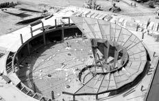
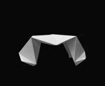
HYPERBOLE exemplifies the potential of folding structures as innovative construction components. The design features an aluminum structure shaped like a hyperbolic paraboloid, or hypar, which is a three-dimensional, double-ruled surface. This surface can be formed using infinite planar, linear elements to create a smooth and elegant profile. The ultra-thin aluminum shell seamlessly merges skin and support (Figure 1.22). Through a process of iterative development and prototyping, HYPERBOLE measures an impressive 22 feet high, 25 feet wide, and 30 feet deep, serving as a dramatic architectural statement that touches down on only three concrete bases ( Figure 1.23). This design not only showcases the aesthetic appeal of folding structures but also highlights their structural efficiency and versatility in construction.
TH 2.0 / TOWNHOUSE 2.0, PATEL ET AL., 2018
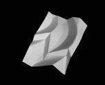
In response to the rapid and changing needs of people, a new architectural model aims to provide shared living spaces for working individuals near traditional employment hubs in London. This research investigates novel architectural geometries and fabrication methods to enable mass customization. Specifically, it explores curve folding as a technique for delivering prefabricated living units that adapt to the evolving needs of communities ( Figure 1. 24-25 ). The project contributes to architectural discourse by demonstrating a new approach to creating livable spaces through intricate shapes derived from folding single flat sheets. By examining curve folding and its digital fabrication possibilities, the proposals envision potential applications at a larger architectural scale ( Figure 1. 26 ). The systematic study of the curved folding topology has significantly impacted the foundational research of FlexFold.
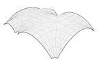
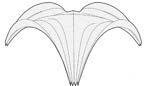
The rain bow gate represents a simple yet dynamic natural geometry, known for its structural efficiency due to its curvature (Figure 1.27). Constructed from flat, lasercut 3mm steel sheets, this geometrically strong and ultra-light structure minimizes both weight and material waste(Figure 1.28). It exemplifies the principles of the Shell Lace Structure, a concept pioneered by Tonkin Liu and engineers at Arup. This innovative design not only highlights the aesthetic appeal of curved forms but also showcases the potential for sustainable construction practices through the effective use of materials and advanced fabrication techniques. Inspired by this, Flexfold went further, exploring lightweight and robust results, and exploring the possibilities of structural applications.
DNIPRO METRO STATION, ZAHA HADID ARCHITECTS, 2021
The Dnipro Metro Station, designed by Zaha Hadid Architects, features a series of visually connected sculpted shell pavilions at ground level, constructed from locally sourced recycled steel ( Figure 1.29). The station entrances are characterized by undulating welded steel forms that rise and arch from newly designed, landscaped public plazas, positioning the entrance pavilions as prominent landmarks. This design demonstrates the potential of folding structures in architectural construction, combining aesthetic appeal with stable structural performance (Figure 1.30). The use of recycled materials further emphasizes sustainability while creating an iconic and functional urban space that enhances the surrounding environment.
Figure 1.30. Dnipro Metro Station elevation view (Zaha, 2021)
Figure 1.27. rain bow gate (Liu, 2012)
Figure 1.29. Dnipro Metro Station isometric view (Zaha, 2021)
Architectural Geometry
INTRODUCTION TO FOLDING STRUCTURE
STRAIGHT CREASES
CURVED CREASES
Growth: Invariable under n-fold rotations about the center
Isometry: Different sizes of tiles
Repetition: Linear repetition in X
Growth: Invariable under n-fold rotations in the grid
Isometry: Different sizes of tiles of triangular shape
Repetition in Grid
Growth: Invariable under n-fold rotations about the center
Isometry: Equal sizes of tiles
Repetition: Independent unit
In architectural design, enclosure and load transfer are always under discussion. Suitable structural systems must also be developed to construct an ideal space. Available structural systems can be categorized into many groups, including vector active, bulk active, and surface active systems. Among these, the Folded Plate Structure constitutes a subclass of surface active structure, allowing for the arrangement of large spaces by folding sheet materials to cover them without additional pillars or support systems (Engel, 1967). The concept of folding plate structure dates back to the early 20th century, when it was first explored through reinforced concrete. From a sustainability perspective, folded plate structures can minimize material usage, thereby presenting a lightweight alternative.
SOM, The Air Force Academy Cadet Chapel, 1962
K Architectures, Domaine de Bayssan Theater, 2021
Studio Gang, Bengt Sjostrom Starlight Theatre, 2003
MARC FORNES & THEVERYMANY, Structural Shingle, 2015
Marcus Abrahamsson & Benoit Croo, The Archipelago Pavilion, 2012
Lake|Flato Architects + Matsys Design, Confluence Park, 2019
EVALUATION FACTORS 2.1.2 SCOPE AND FRAMEWORK
METHODS DRAWING UNFOLDING PLAN LASERCUTTING FOLD AND TEST
OBJECTS
Patterns
PURPOSE
Structural Strength
Vertical Load-bearing Capacity
Horizontal Load-bearing Capacity
Load-bearing Capacity After Constraint Base
Load-bearing Capacity After Subtract Surface
Material Consumption (Shaded Area of Unfolding Plan)
Structure
Geometric Topology
Connection Variation (Multi-directional Development) Easy to Fold (Fabricate and Assembly)
Material Consumption (Shaded Area of Unfolding Plan)
Number of Stable States
Prototypes (Architectural Structure and Furniture)
Geometric Optimization
Developability (Single-surface or Multiple-surface) Interchangeability
2D
3D
2.2.1 FOLDING PATTERN EXPERIMENT (2D)
STRAIGHT CREASES CURVED CREASES
STRAIGHT : A
BOTH STRAIGHT AND CURVED : B
CURVED: C
CHAPTER 2: ARCHITECTURAL GEOMETRY
2.2.2
FOLDING
PATTERN EXPERIMENT (2D)
2.2.2 FOLDING PATTERN EXPERIMENT (2D)
Result 1.Curved and straight folding patterns have similar load-bearing performance.
Result 2.The both presence of curves and straight folding lines can significantly enhance the structure.
Result 3. Structural strength can be increased by adding and subdividing structural lines.
Result 4. Constraining the base can prevent collapse to a certain extent.
Result 5. The movement of the radial center point has little impact on vertical load-bearing.
Result 6. Spatial structure has stronger lateral stability than others.
2.2.2 FOLDING PATTERN EXPERIMENT (3D)
ARCH PLEAT PATTERNS
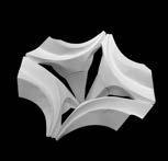
In this experiment, FlexFold takes two-dimensional patterns of the Arch Pleat (C10) and transforms them into a three-dimensional spatial model. This transformation builds upon the findings of a previous experiment, which serves as a foundation for current work. The primary objective of this process is to explore and develop the final folding prototype, allowing to investigate the interplay between form and structure in a more complex, three-dimensional context.
The first step is to individually change the folding shapes of 3 prototypes by three means based on the unfolding plan: structural line deformation, density and plan subtraction.
The results and principles:
1. Curved Pleat (PATTERN 3) is the easiest to fold, while V pleat (Prototype 1) is the hardest.
2. Radial Pleat (PATTERN 2) overlaps when folded with a full sheet of paper.
The second step is to individually constrain, twist and invert the basic spatial prototypes.
C9
C10
C8
Arch Pleat 1
Arch Pleat 2
2.2.2 FOLDING PATTERN EXPERIMENT (3D)
The second step is to individually constrain, twist and invert the basic spatial prototypes.
By constraining the vertices and edges of the Arch Pleat, various threedimensional forms occur, as the foundation for the next iteration of topology. This process highlights how manipulating this variable can result in a range of distinct structures.
Additionally, the limitations imposed on the folding angle significantly influence the static form of the shell, further affecting its overall geometry and stability.
Here are the results and principles:
1. There exist ultimate and initial folding limitations.
2. The Spatial scale of the folding structure is related to the hinge angle.
2.2.2
FOLDING PATTERN EXPERIMENT (3D)
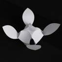
In this experiment, FlexFold converts two-dimensional V Pleat Patterns (C10) into a three-dimensional spatial model. This transformation builds on the results of a previous experiment, which provides the basis for the current work. The main goal of this process is to explore and develop the final folding prototype, enabling an investigation of the interplay between form and structure in a more intricate, three-dimensional context.
The first step is to individually change the folding shapes of 3 prototypes by three means based on the unfolding plan: structural line repeat, deformation and plan subtraction.
The results and principles:
1. When there is an intersection of mountain line (red line) and valley line (blue line), leads to difficult to fold at the intersection
The second step is to individually constrain, twist and invert the basic spatial prototypes.
A2
A10
Pleat 1
Pleat 2 V Pleat 3 V Pleat 4
2.2.2 FOLDING PATTERN EXPERIMENT (3D)
The second step is to individually constrain, twist and invert the basic spatial prototypes.
By constraining the vertices and edges of the Arch Pleat, various three-dimensional forms emerge, laying the groundwork for the next iteration of topology. This process demonstrates how manipulating these variables can produce a diverse array of distinct structures.
The results and principles:
1. There exist ultimate and initial folding limitations.
2. The Spatial scale of the folding structure is related to the hinge angle.
V Pleat 1
V Pleat 2
V Pleat 3
V Pleat 4
Folding Creases Constraint Edge Constraint Point
BASIC (NO CONSTRAIN)
CONSTRAIN
CONSTRAIN
2.2.3 FOLDING PATTERN EXPERIMENT (3D)
There exist four types of folding ways:
Continuous Structural Lines:
1. Creases are continuous and connected by cutting edges/sides.
Discontinuous Structural Lines:
1. Creases are discontinuous and connected by cutting edges/sides to crease(line).
2. Side to Side: Creases are discontinuous and connected by cutting edges/sides.
3. Surface Overlapping: Creases are discontinuous and connected by surfaces.
By evaluating the connection variation, multi-directional developability and whether it is easy to fold/ fabricate, the curved folding structure with various branches is chosen as our final folding prototype.
C9_1
C9_2
C9_3
C9_4
C9_5
C9_6
C9_7
C9_8
C9_10
C9_11
C9_12
C9_13
C9_14
C9_15
C8_1
C8_2
C8_3
C8_4
C8_5
C8_6
C8_7
C8_8
C8_10
C8_11
C8_12
C8_13
C8_14
C8_15
CX_1
CX_2
CX_3
CX_5
CX_6
CX_7
CX_8
CX_10
CX_11
CX_12
CX_13
CX_14
CX_15
CX_4
B3_1
B3_2
B3_4
B3_5
B3_6
B3_8
B3_12
B3_10
B3_11
B3_14
B3_17
B3_18
A2_1
A2_2
A2_3
CHAPTER 2: ARCHITECTURAL GEOMETRY
C3_1
C1_1
C1_2
C1_3
C1_4
C0_3
C1_5
A1_1
A1_5
A1_7
C3_3
C9_16
C3_2
C0_1
C0_2
Boundary Connection Surface Mountain Line Valley Line
Constraint Point
Building on the previous experiment, FlexFold will evaluate the load-bearing capacity under three conditions: after constraining the base, subtracting the surface, and considering the ease of folding for fabrication and assembly. FlexFold also assesses material consumption and the developability of structures, whether single or multi-surfaced. Six prototypes have been selected for further exploration of architectural construction and aggregation. The next phase will focus on refining fabrication methods and optimizing topology to explore the potential of lightweight and folding structures in architectural applications.
PROTOTYPE 1
PROTOTYPE 4
PROTOTYPE 2
PROTOTYPE
PROTOTYPE
PROTOTYPE
CX Collection Generation
& B3Collection Generation
C1 Collection Generation
A2 Collection Generation
C9 Collection Generation
C8 Collection Generation
Fabrication 03
Developable Surface
Topology Optimization
Interface Test
1:5 Paper Prototype
3.1.1 FABRICATION FRAMEWORK
FlexFold explores innovative strategies and tools in the architectural industry, focusing on straight and curved crease technology as well as modular prefabrication systems that facilitate rapid transport and assembly. The process emphasizes the use of sustainably manufactured prefabricated modules to ensure efficient transportation and assembly. To achieve this goal, the fabricated methodology involves three key steps. The first step is topology optimization, which includes exploring developable surfaces and conducting interface tests to create a paper prototype. The second step involves translating the design into metal by experimenting with various digital fabrication machines to assess material applications on sheet metal, ensuring that it is easy to fold, developable, and lightweight. Finally, the process concludes with folding and assembling the sheet material to form the prototype.
Through systematic exploration of topology optimization, material selection, and fabrication techniques, FlexFold aims to develop a sustainable and precise folding solution. This approach supports further architectural applications, offering a reliable method for creating easily foldable and accurate structures.
Prototypes developed from multiple folding experiments in Chapter 2
Physical Paper Experiment
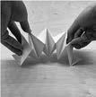
Developability is crucial for fabricating the prototype, ensuring that the surface can be folded and assembled effectively (Figure 3.1). To achieve this, digital modelling and physical experiments are conducted in parallel, allowing for double-checking that the prototype components can be folded from a single sheet. Both Kangaroo and Maya are employed in digital modelling, using gravity simulations to replicate the folding process. Additionally, Gaussian curvature analysis and physical paper tests are used to experiment with and validate the developable surfaces (Figure 3.2).
Developable surfaces have two main principles.
1. Ruling lines are straight. (Gaussian Curvature (U*V) is 0.)
2. The sum of the angles of the outgoing/incoming edges on a creased vertex has to be 360°. has to be 360°.
METHODOLOGY OF TOPOLOGY OPTIMIZATION
Figure 3.1. Developable surface optimization
Figure 3.2. Gaussian curvature analysis
Gaussian Curvature Analysis
Kangaroo Physics
3.2.1 DEVELOPABLE SURFACE
ARCH)
ARCH)
By adjusting various gravity settings in Maya and constraining vertices, the developable surface is modelled.
The developability of various topologies is tested, with each topology resulting in a distinct arch pleat. Input Points:
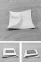
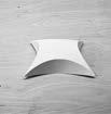
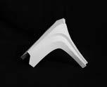
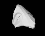
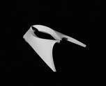
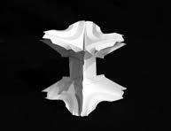
After optimizing the developable surface in the digital model, the physical paper experiment may challenge the digital results. For instance, while the digital model of Prototype 2 shows a Gaussian curvature analysis of zero (Figure 3.3), indicating a developable surface, it is actually a composite developable surface. Only one part of the surface is truly developable, rather than the entire arch.
As a result, when the paper is folded, it does not form an arch but instead creates a series of separated surfaces that together suggest an arch ( Figure 3.4 ). This outcome demonstrates that the curve cannot span the x, y, and z axes, making it impossible to create an arch pleat from a single sheet (Figure 3.5).
This underscores the importance of physical paper experiments in testing developability, as they can reveal limitations not apparent in digital modelling.
Figure 3.5. Test of developability Result: The curve cannot span the x, y, and z axes, unable to make a pleat arch by one sheet.
Figure 3.4. Physical paper model of prototype 2
Pure Developer Surface
Folding a sheet of paper only results in pleats and curves, not an arch form.
Composite Developer Surface
By splitting the component apart each strip is developable, and the shape of a pleated arch can be formed.
Figure 3.3. Digital model of prototype 2 3.2.1 DEVELOPABLE SURFACE
The iterations highlight the distinction between the continuous roof and column while also optimizing the interface into a single sheet.
Iterations of the topology reveal differences between a split roof and a singlesheet roof, which also result in changes to the interior form.
Trapezoidal
If the roof is taken as a whole, the space becomes an arch
The crisscross roof surfaces become curves by changing the first mountain pleat
The new iteration reveals that the crisscross roof surfaces have been transformed into curves, making them easier to fold and less prone to tearing.
The extruded connection faces of the 1/2 columns can be aligned without gaps
The topology iteration demonstrates different angles of "a", resulting in various scales for Prototype 3.
3.2.2 TOPOLOGY OPTIMIZATION | PROTOTYPE 3
Iteration 00
Initial Unfold Plan
1/4 Unfolding plan of Prototype 03
Iteration 01
Add Structural Line
Reduce the possibility of interface tearing
Iteration 03
Split into Roof and Column
Increased folding simplicity
Based on the considerations for machine fabrication, an additional structural line has been incorporated to separate the roof and column, facilitating better folding.
CHAPTER 3: FABRICATION
Avoid tearing the interface, one more structural line is added
Figure 3.7. Prototype 3 tearing in the interface
Figure 3.6. Prototype 3
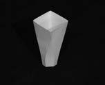
3.2.2 TOPOLOGY OPTIMIZATION | PROTOTYPE 3
Extructed Interface Face: M3 Screws (3mm)
Overlapping Interface Face: Rivet (4mm)
Tolerance: ± 0.16mm
There are two interfaces: overlapping interface and extructed interface. and round the edge, the cutting edge avoids the tearing of the intersection of the folding line.
The physical model with a 0.8 mm card to simulate the thickness of the sheet material, tests the two interfaces.
Figure 3.9. Detail of paper model
Figure 3.8. Paper model of prototype 3 column
Increasingly, prototype optimizations have been achieved through various paper model experiments, ultimately leading to a finalized prototype model for further fabrication.
The iterations have removed the base, leaving the topology as a slab and column.
The next iteration adjusts the scale of the slab to achieve a more optimal proportion between the slab and the column.
Building on the established slab, various column studies are conducted to investigate structural performance and aesthetics, aiming to optimize the column in conjunction with the slab.
3.2.3 TOPOLOGY OPTIMIZATION | PROTOTYPE 1
Building on the established slab, various column studies are conducted to investigate structural performance and aesthetics, aiming to optimize the column in conjunction with the slab.
3.2.3 TOPOLOGY OPTIMIZATION | PROTOTYPE 1
Based on the decision regarding the column and considerations for fabrication, the column will be divided into a capital and a column. The variety of capitals to achieve the stable connection between slab and column.
CHAPTER
3.2.3 TOPOLOGY OPTIMIZATION | PROTOTYPE 1
The
Figure 3.11. Prototype 1 paper model capital detail
Figure 3.10. Prototype 1 paper model
Prototype optimizations have been progressively accomplished through a series of paper model experiments, culminating in a finalized prototype model ready for further fabrication.
By translating the material from paper models to metal sheets, we begin by applying the stitching pattern to the metal. This process allows us to test various snitching (folding line) patterns, revealing different levels of folding difficulty as well as the accuracy of the folding angles and whether the material tears during the process. This method enables FlexFold to effectively translate the paper model into a metal prototype, complete with optimized folding tectonic details.
Consequently, the water jet cutter ( Figure 3.12-13 ) will be employed in this experiment to test three different materials using nine types of stitching line patterns. This approach will enable FlexFold to achieve improved tectonic details in larger models. Additionally, digital fabrication will help us understand the distinctions between the various fabrication machines and their specific features, as well as the variety of prototypes that each machine can produce.
After fabricating the metal sheets using the water jet cutter, they will be folded manually to test the different materials and stitching patterns, which will affect the accuracy of the folding angles and help determine the limitations of those angles (Figure 3.14-15). The stitching lines will be assessed alongside three types of materials. Furthermore, the difficulty of folding is a crucial criterion in our evaluation of the materials and stitching patterns.
Figure 3.13. Waterjet cutter process
Figure 3.12. Cutting process
Figure 3.14. Bending mild steel (0.8mm) manually
Figure 3.15. Bending Aluminum (0.8mm) manually
Ease of Folding
Aesthetic Appeal
Material Deformation
Folding Precision
Ease of Folding
Aesthetic Appeal
Material Deformation
Folding Precision
Ease of Folding
Aesthetic Appeal
Material Deformation
Ease of Folding
Aesthetic Appeal
Material Deformation
Folding Precision
Ease of Folding
Aesthetic Appeal
Material Deformation
Folding Precision
Ease of Folding
Aesthetic Appeal
Material Deformation
Folding Precision
Ease of Folding
Aesthetic Appeal
Material Deformation
Folding Precision
Ease of Folding
Aesthetic Appeal
Material Deformation
Folding Precision
Ease of Folding
Aesthetic Appeal
Material Deformation
Folding Precision
3.3.1 STITCHING PATTERN
Ease of Folding
Aesthetic Appeal
Material Deformation Folding Precision
Ease of Folding
Aesthetic Appeal
Material Deformation Folding Precision
Ease of Folding
Aesthetic Appeal
Material Deformation Folding Precision
Ease of Folding
Aesthetic Appeal
Material Deformation
Folding Precision
Ease of Folding
Aesthetic Appeal
Material Deformation Folding Precision
Ease of Folding
Aesthetic Appeal
Material Deformation Folding Precision
Ease of Folding
Aesthetic Appeal
Material Deformation
Folding Precision
Ease of Folding
Aesthetic Appeal
Material Deformation Folding Precision
Ease of Folding
Aesthetic Appeal
Material Deformation Folding Precision
Ease of Folding
Aesthetic Appeal
Material Deformation
Folding Precision
Ease of Folding
Aesthetic Appeal
Material Deformation
Folding Precision
Ease of Folding
Aesthetic Appeal
Material Deformation
Folding Precision
Ease of Folding
Aesthetic Appeal
Material Deformation
Folding Precision
Ease of Folding
Aesthetic Appeal
Material Deformation
Folding Precision
Ease of Folding
Aesthetic Appeal
Material Deformation
Folding Precision
Ease of Folding
Aesthetic Appeal
Material Deformation
Folding Precision
3.3.1 FABRICATION MACHINE
FILE ADJUSTMENT:
The Folding Structure Line will be engraved as a continuous line. The Holes inputted by a drilling point.
FOLDING LINE: Engrave Line (V-Drill: 1.5mm )
HOLE: Drill holes with a 5mm drill
Thickness 0.8 mm
FILE ADJUSTMENT:
The Folding Structure Line will be cut as a dashed line. The Holes are drilled by pillar drill manually. The precision of the plasma Cutter does not support holes smaller than 5mm.
FOLDING LINE: Dash Line (Cut Line)
HOLE: Drill holes Afterwards
In line with FlexFold's goal of creating lightweight and sustainable folding structure prototypes, this experiment will take into account various digital fabrication machines. We aim to evaluate the efficiency and outcomes of three different machines. Additionally, different machines require specific file inputs, which will also influence the final results.
Material Steel Sheet
Thickness 0.8 mm
FILE ADJUSTMENT:
The Folding Structure Line will be cut as a dashed line. The Holes are included in the laser cutting process. The tolerances is ± 0.16 mm.
FOLDING LINE: Dash Line (Cut Line)
HOLE: Holes Included 4.16 mm and 3.16 mm
Material Aluminum Sheet
Thickness 0.9 mm
CNC
Material Aluminum Sheet
PLASMA CUTTER
LASER CUT
The first experiment with the CNC machine failed due to excessive drill temperature, which melted the aluminum sheets and resulted in very rough edges.
The second experiment with the CNC machine also failed for the same reason. Despite reducing the revolutions per minute, the aluminum sheets still melted due to excessively high temperatures.
CNC
CNC
3.3.1 FABRICATION MACHINE | PLASMA CUTTER
Autodesk Fusion diffusion is the necessary software used for inputting data into the plasma cutter. And, the minimum diameter for the plasma cutter is 4 mm, which means that holes for screws and rivets cannot be fabricated using this machine.
The plasma cutter limits material selection, as it can only cut steel sheets. As a result, the outcomes from the plasma cutter will be difficult to fold, also necessitating further processing to polish the surface.
Figure 3.17. Plasma cutter simulation
Figure 3.16. File for plasma cutter
Figure 3.18. Process of cutting
Figure 3.19. Operating with plasma cutter
3.3.1 FABRICATION MACHINE | PLASMA CUTTER
The plasma cutter's limitation prevents it from fabricating small holes. Therefore, two different types of holes will be manually drilled using a pillar drill.
The plasma cutter operates by melting the material, which results in splattered edges on the steel sheets. Subsequent grinding is necessary to achieve a smooth, polished edge on the unfolded surface.
Figure 3.21. Manual drilling with pillar drilling
Figure 3.20. Unfold sheet from plasma cutter
Figure 3.23. Grinding
Figure 3.22. Unfold sheet after grinding
DIFFICULTY
In the attempts with three machines, FlexFold aims to find an efficient solution for fabricating a lightweight and sustainable prototype. Throughout the experimental process, only two of the machines were able to successfully produce the prototype. The plasma cutter successfully achieved Prototype 3, but it took two weeks to fabricate, followed by manual drilling of holes and polishing. In contrast, the laser cutter provided a more efficient solution for cutting both holes and stitching lines, reducing the time needed for processing the unfolded sheet. As a result of this experiment, the laser-cut aluminum sheets demonstrated better folding difficulty and angle accuracy, with the total weight of prototype 3 being just 3 kg.
Computation and Design
To enable the stacking of the prototype as a modular structure for multi-story applications, additional designs for a double-layer prototype are being developed to achieve a more functional and realistic assembly. This phase will involve the use of various materials to consider during the transformation of the single prototype into an architectural vision.
Assembly Procedure 4: Pour Concrete Columns and Floor Slabs
Assembly Procedure 5: Add Finishes
Assembly Procedure 6: Complete the Assembly
For further aggregation based on topological thinking, the FlexFold system involves more than just the repetition of a single model; it incorporates changes in topology as multiple modules come together.
CHAPTER 4: COMPUTATION AND DESIGN
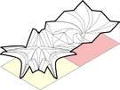
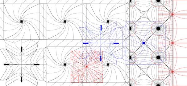
In this chapter, the prototypes will be presented in colour to facilitate further colour voxel aggregation in an architectural context. The varying scales of colour blocks will represent different functional spaces, with the spatial characteristics of the prototypes guiding the definition of each space's function.
The composability of prototype topology establishes the rules for spatial aggregation, allowing for various connections between modules while also limiting the combinations of prototypes. It defines the relationships among the prototypes, including border connections, overlapping, and nesting.
CHAPTER 4: COMPUTATION AND DESIGN
PROJECT DEVELOPERS
Lead the conception, planning, and execution of projects
Multi-user Platform: facilitate the customization of spaces
USERS / CONSUMERS
Rent creative space for their artists’ production and activity
Based on the research, a multi-user platform has been established to enhance flexibility for user customization, enabling multiple users to collaborate on design. Project developers will customize the architectural planning, while users can personalize the interior partitions and finishes of their units, etc.
In the creative industry, there are three types of creative spaces that support cultural production: studios, maker spaces, and workspaces.
Depending on the number of occupants, various proposals for creative spaces outline the activities within the units, featuring different scales and shapes. This approach illustrated colour voxels for aggregation into an architectural design as foundation information.
Studios: Fewer windows.
Partition walls separate storage from workbenches.
Makerspaces: Minimal windows.
Partition walls isolate workbenches from equipment and machines.
Workspaces:
Designed for offices needing more natural light. Partition walls distinguish private offices from hybrid work areas.
≈10 Artworks (Wall) ≈7 Artworks (Display Plinth)
m2 ≈20 Artworks (Wall)
Artworks (Display Plinth)
The scale of the public space is determined based on the workspace and working pod, although the final configuration largely depends on the project developer's decisions. The hot desking area accommodates individuals without assigned desks, while the exhibition space is designed for creative workers to engage in various activities.
In the next phase of the floor plan generation strategy, various functions will be represented by distinct colour blocks. This method will enable project developers to plan and define the construction layout more effectively. However, a colour block is more than just a visual element; it contains input information with assigned weighting.
The floor plan generation methodology outlined in Egor's paper "Computeraided approach to public buildings floor plan generation: Magnetizing Floor Plan Generator" (Egor, 2020) prioritizes accommodating diverse space programs within site constraints and function adjacency relationships (Figure 4.2). It operates based on inputs like room programs, required connections, entrance points, and site boundaries.
This data can be represented through various adjacency matrices and connectivity graphs, according to graph theory principles ( Figure 4.3 ). These diagrams will then be transformed into floor plan layouts. The adjacency of functions is also hierarchical based on basic building code regulations and user needs, which are expressed in the Adjacency Matrix.
Figure 4.1. Input Preparation: Adjacency Matrix Spatial adjacency hierarchy for function relationships.
Figure 4.2. Input Preparation: Adjacency Matrix
Figure 4.3. Connectivity graph
Egor's Magnetizing Floor Plan Generator (Egor, 2020) can convert the Adjacency Matrix into the Room Connectivity Graph, incorporating elements such as site boundaries, room types, areas, connections, and entrance locations. This approach enables the creation of numerous floor plan solutions alongside the adjacency graph (Figure 4.5). This approach not only streamlines the design process but also offers flexibility and efficiency in creating optimal spatial arrangements (Figure 4.4).
Figure 4.5. Connectivity graph with function weight
Figure 4.4. MFPG_result
4.2.3 FLOOR PLAN GENERATION
Makerspace Type
Workspace
Total Area: 1474 m2
Location: Curzon St and Bolton St, W1J, London
MFP_Generator (Egor, 2020) can transform the Adjacency Matrix into a Room Connectivity Graph, which includes factors such as site boundaries, room types, areas, connections, and entrance locations. This method facilitates the development of multiple floor plan solutions in conjunction with the adjacency graph (Figure 4.6).
Figure 4.6. Input Preparation: Adjacency Matrix
4.2.3 FLOOR PLAN GENERATION
The key highlight of this tool lies in its ability to adapt to various site shapes, achieved through experimentation across multiple sites. The spatial squares will be organized and harmonized with one another, taking into account the constraints imposed by the site boundaries. Furthermore, altering the sizes of different areas distinct outcomes.
4.2.4 FLOOR PLAN GENERATION | MUTI-FLOORS
The floor plan methodology maintains a planar representation, but further architectural development introduces a layered approach, forming a 2.5-dimensional representation through vertical stacking of three-floor plans. This involves incorporating a public space serving as vertical access connecting each floor plan, along with the addition of double ceiling spaces to reduce the shape of the second-floor plan's site boundary.
4.2.4 FLOOR PLAN GENERATION | MUTI-FLOORS
MFPG_FLOOR PLAN
MFPG define the program and circulation
Based on the prototype Feature, the different floor heights of the voxel occur
By utilizing the layered approach, stacking the colour voxels together creates a multi-layered structure. Incorporating voxels with double or even triple heights further enhances the design by fostering intriguing spatial relationships within the construction.
This versatility supports FlexFold's objective of developing lightweight, sustainable prototypes that can adapt to different functions and user needs while promoting creativity and collaboration in the built environment.
3D VOXEL AGGREGATION voxel clusters appear at different spatial relationship
3D VOXEL
PROJECT DEVELOPER
Customize studio, workspace, and maker space quantities
Determine private/public spaces.
Site Selection
Number of Floor
Type of Public Space
Number of Public Space
Type of Unit Space
Number of Unit Space
Visualization
Site Location: W1K 1HF London
Site Boundary: 233 m
Site Area: 2490 m2
Number of Floors: 3
Gross Floor Area: ~5802 m2
Public Space Number
Hot Desking Workspace: 4
Exhibition: 8
Cafe / Kitchenette: 4
Unit Space Number
Workspace A (83 m2): 1
Workspace B (175 m2): 2
Makerspace A (36 m2): 1
Makerspace B (54 m2): 0
Makerspace C (72 m2): 0
Studio A (9 m2): 6
Studio B (18 m2): 15
Studio C (36 m2): 2
The developer platform allows users to customize parameters that define the function and spatial arrangement of the site. Users begin by specifying the number of floors and using spatial blocks to outline workspaces and public areas, shaping the form of an artist community. This dynamic feedback encourages creativity, ensuring each iteration reflects users’ unique visions, and fostering a vibrant environment for artistic expression.
On the platform, developers take on the role of users and input various parameters to personalize the space. They choose the site, the number of floors, and the types and quantities of sale spaces (such as studios, workspaces, and makerspaces), as well as public spaces (like hot desking areas and exhibition areas). The platform then generates layers of floor plans and visualizations of the customized architecture, presenting different layout and appearance options.
CHAPTER 4: COMPUTATION AND DESIGN
Customization Procedure 1
Customization
Customization Procedure 4
Customization Procedure 2
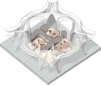
In the FlexFold system, the kit of parts is derived from the FlexFold family tree, ensuring flexibility and lightweight folding elements. The hierarchy within the folding collection determines the scale of each prototype, with some functioning as structural modules, working pods, and furniture.
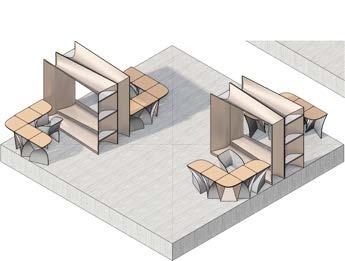
The design of the working pod is based on Prototype 5 (Figure 4.7), which is part of the V Pleat Patterns collection. Through repetition and mirroring, this prototype evolves into a foldable working pod. Based on the nature of origami, the working pod is capable of transforming into various spatial configurations, adapting to different needs and environments.
CHAPTER 4: COMPUTATION AND DESIGN
Smaller-scale folding prototypes, such as furniture (Figure 4.8), can easily transition between a flat sheet and a three-dimensional form. This capability, rooted in the principles of origami, allows for simple folding and unfolding. As a flexible and movable element, folding furniture offers significant potential for easy assembly and disassembly, making it highly adaptable to different spaces and needs.
A2
A2_13
A2_12 A2 C0_3
C0_3
Figure 4.7. Working Pod
Figure 4.8. Folding Chair
Chair 1 (C1) Generated From C0_3
CHAPTER 4: COMPUTATION AND DESIGN Chair 2 (C2) Generated From C1_5
Table 1 (T1)
From C3_2 Chair 3 (C3)
From C1_5
CHAPTER 4: COMPUTATION AND DESIGN
= 2100mm
Partition Wall 2 Width = 3000mm Mode 1: Without Chair
Mode 2: With Chair
Storage Wall 1 Width = 1500mm
Partition Wall 1 Width = 1500mm Storage Wall 2
= 1800mm Mode 1: Without Chair
= 2100mm Mode 2: With Chair
= 1800mm
Mode 1: With Bench
Working Pod Mode 1: Semi Open
= 3000mm
= 2100mm
4: COMPUTATION AND DESIGN
CHAPTER
Mode 2: With Shelves
Mode 1: Without Shelves
Mode 2: With Shelves
Boundary Connection Surface Mountain Line Valley Line
The design of the working pod originates from Prototype 5, which belongs to the V Pleat Patterns collection. Utilizing the principles of origami, the working pod can adjust to different spatial conditions, making it adaptable to various needs and environments. It is typically nested within other structural prototypes, further enhancing its versatility. As the form of the work pod transforms, its privacy and openness can be manipulated by the user.
4: COMPUTATION AND DESIGN
CHAPTER
Work
CHAPTER 4: COMPUTATION AND DESIGN
Work
CHAPTER 4: COMPUTATION AND DESIGN
Capacity: 15 People
Capacity: 30 People Area: 175 m2
3
Utilizing the architecture provided by the developer platform, consumers within the artist community can select and personalize their units, tailoring interior functions and finishes to suit their creative production and exhibition needs. This customizable approach enhances creativity and fosters a sense of ownership, promoting collaboration and innovation within the community.
By allowing users to modify various aspects of their environments, such as layout, color schemes, and functional elements, the platform promotes a dynamic atmosphere that is conducive to creative exploration and expression. This personalization helps create spaces that reflect the unique identities and artistic visions of the residents, making the community a vibrant hub for collaboration and innovation.
Moreover, the flexibility inherent in this system encourages interaction among user, developer and designer, leading to collaborative projects and shared exhibitions that enhance the community's overall cultural richness. By providing the tools and resources for customization, the developer platform empowers user to engage fully with their surroundings, ultimately fostering a supportive environment where creativity can thrive and evolve.
COMMUNITY USER / TENANT
Consumers can customize their space preferences by selecting available unit and functions for purchase or rent.
Unit Type: Workspace B
Selection
Type of Functions
Number of Function
Specify Finishes
Unit Location: Ground Floor
Unit Area: 175 m2
Number of Users: 28 People
Function: Number of Users
Open Office : 20 people
Privated Office: 2 people
Meeting Room: 6 people
Kitchenette: 2 people
Cafe/Dining: 4 people
Function: Area
Open Office : 72 m2
Privated Office: 12 m2
Meeting Room: 12 m2
Kitchenette: 14 m2
Cafe/Dining: 36 m2
Visualization
Finishes
Hardwood Floor
Grey Painted Wall
Users can further customize their chosen units by utilizing the FlexFold module kit of parts to design interior functions. This process results in floor plan layouts that include furniture, partitions, and more. Additionally, users can visualize their customized spaces in real-time, enabling immediate feedback and adjustments.
Bibliography and Reference
BOOK AND JOURNAL
Allen, Steph, et al. “Making Space: Developing and Sustaining Affordable Artists’ Studios and Creative Workspaces.” creativeunited.org.uk . Creative United, July 2016. Print.
Demaine, Erik D. et al. “Reconstructing David Huffman’s Legacy in Curved-Crease Folding.” (2016).
Demaine, Erik D. et al. “Curved Crease Folding – a Review on Art, Design and Mathematics.” (2011).
Egor, Gavrilov et al. “Computer-Aided Approach to Public Buildings Floor Plan Generation. Magnetizing Floor Plan Generator.” Procedia Manufacturing 44 (2020): n. pag. Web.
Friedman, Tal. “Foldfinding- a Novel Approach to the Design and Fabrication of Folded Structures.” Proceedings of the IASS Annual Symposium 2016 (2016): n. pag. Print.
Johnsson, Helena, Gustav Jansson, and Patrik Jensen. Modularization in a housing platform for mass customization (2013): n. pag. Print.
Jackson, Paul. Complete Pleats: Pleating Techniques for Fashion, Architecture and Design. London: Laurence King Publishing, 2015. Print.
Kilian, Martin et al. “Curved Folding.” ACM Transactions on Graphics 27.3 (2008): 1–9. Web.
Lobos, Danny, and Dirk Donath. “The Problem of Space Layout in Architecture: A Survey and Reflections.” Arquitetura Revista 6.2 (2010): 136–161. Web.
Mitani, Jun. Curved-Folding Origami Design. Boca Raton, FL: CRC Press, Taylor & Francis Group, 2019. Print.
Peiris, P. A. et al. “Challenges in Transport Logistics for Modular Construction: A Case Study.” Lecture Notes in Civil Engineering 266 (2022): n. pag. Web.
Rana, Vighneshkumar, and Vishal Singh. “How May Modular Construction Transform the Built Environment Ecosystem?” IFIP Advances in Information and Communication Technology 667 (2023): 506–515. Web.
Robeller, Christopher, and Yves Weinand. “Interlocking Folded Plate – Integral Mechanical Attachment for Structural Wood Panels.” International Journal of Space Structures 30.2 (2015): 111–122. Web.
Sekularac, Nenad, Jelena Ivanovic-Sekularac, and Jasna Cikic-Tovarovic. “Folded Structures in Modern Architecture.” Facta universitatis - series: Architecture and Civil Engineering 10.1 (2012): 1–16. Web.
Vlachaki, Evangelia and Liapi, Katherine A.. "Folded surface elements coupled with planar scissor linkages: A novel hybrid type of deployable structures" Curved and Layered Structures, vol. 8, no. 1, 2021, pp. 137-146. https://doi.org/10.1515/cls2021-0013