
Sutton Tools Code System – explained
Sutton Tools item # system makes it easier to identify a product. The codes are based on a universal prefix and suffix system.
Prefix (Catalogue Code) – is alpha numeric, and is unique to a specific product range. The letter is relevant to the type of tool, and the number refers to a product range.
B - Burrs
C - Countersinks
D - Drills
E - Endmills
L - Literature
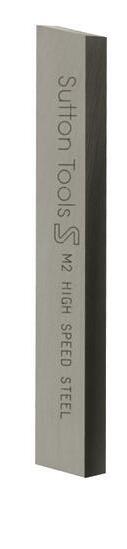
M - Toolbits & Needle Files
R - Reamers
T - Taps
Z - Tool Holders / Chucks
Suffix (Size Ref.) – in most cases is relevant to the diameter or size reference of an item and is based on a metric value.
For example 5mm = 0500, and 1/4" = 0635 (inch converted to decimal). Suffix can also refer to set code or number of pieces in a set.
Benefits of the coding system
• Range identification simplified.
• Search online by range using catalogue code.
Understanding your Sutton Tools Catalogue
Discount Group (A0202 – Z1108)
All product groups have been given a discount group number. These codes enable our distributor partners to identify their discounts on any particular product.
Material
This highlights what the product is made of. (e.g. VHM = Carbide, HSS = High Speed Steel) For the full list of explanation, refer to page 201 of the technical information section.
Surface Coatings
Many of our products have various surface coatings to improve the performance. Surface coatings improve productivity by increasing speeds and feeds and reducing friction related problems.
Symbols
For all of our product pages you will find symbols which depict what specifications these products were made to. Symbols have been used to simplify product identification. A full list of symbols can be found at the start of this catalogue.
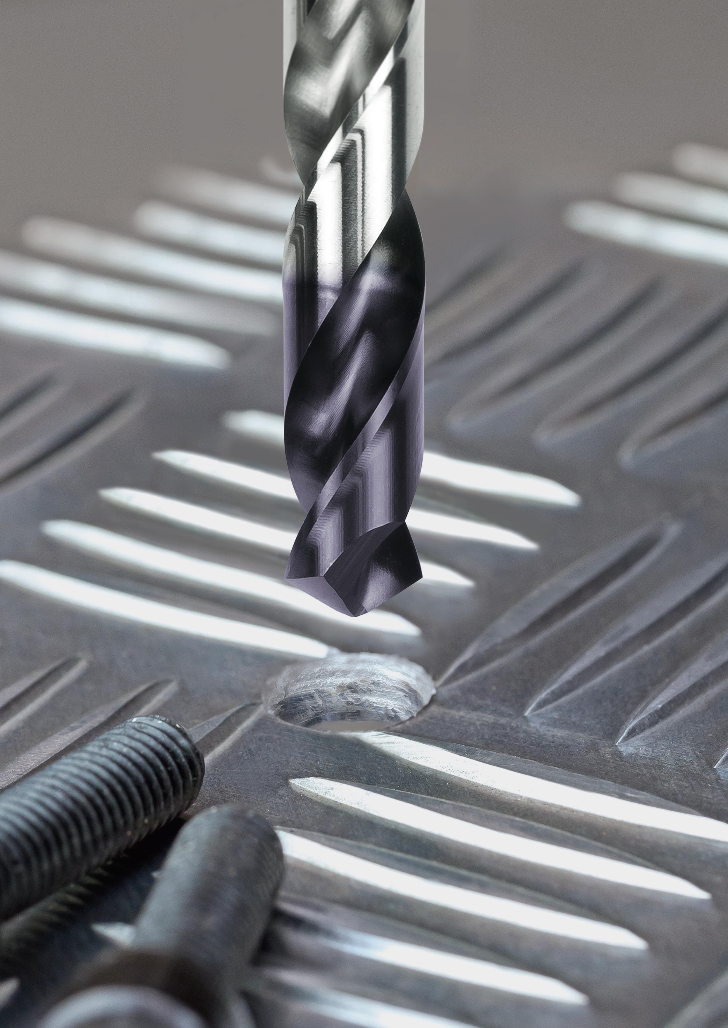
 D101 0150
D101 0150 = D(Drill) 101(Jobber) 0150(1.5mm) Standard Regular length 5 x D max. working depth 60° Metric thread form
examples are: Contents 183 57 65 179 11 121 141 157 Drills Countersinks & Counterbores
Catalogue Code Size Ref. Item #
Some common
ISO Taps
HSS Endmills Reamers
Other i Information
Carbide Burrs
Drills
ISO Taps
ISO Taps Metric, Gun, N
ISO Taps Metric, Spiral Flute, N
ISO Taps Metric, Straight Flute, N, Left Hand
ISO Taps Metric, Straight Flute, Oversize
ISO Taps Pipe, G (BSPF), Spiral Flute
ISO Taps Pipe, G (BSPF), Spiral Point Gun 115
ISO Taps Pipe, G (BSPF), Straight Flute 115
ISO Taps Pipe, National Series
ISO Taps Pipe, Rc (BSPT), Straight Flute 118
ISO Taps Pipe, Rp & Pg Series, Straight Flute 118
ISO Taps UNC, Forming, Single Coolant Groove
ISO Taps
Roughers HR (fine), R30 NH, Regular
Roughers NR (normal), R30 WN, Long
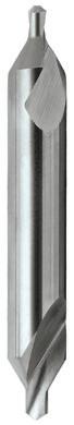
Roughers NR (normal), R30 WN, Regular
Roughers Woodruff Cutter, Threaded
Slot Drills 2 Flute, R30 N, Long
Slot Drills 2 Flute, R30 N, Long
Slot Drills 2 Flute, R30 N, Regular
Slot Drills Ballnose, 2 Flute, R30 N, Long
2
Jobber Sets – Imperial Drills Finder 12 Drills Centre 52 Drills Jobber, Heavy Duty 31 Drills Jobber, R40, INOX 34 Drills Jobber, Silver & Blue Bullet 18 Drills Left Hand Cobalt 33 Drills Long Series 39 Drills Morse Taper Accessories 48 Drills Morse Taper Shank 43 Drills Morse Taper Shank, Heavy Duty 46
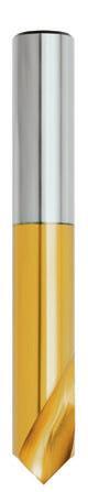
Drills
Morse Taper Shank, Long Series 47 Drills NC Spotting 53 Drills Panel, Double Ended 50 Drills Panel, Single Ended 50 Drills Reduced Shank 49 Drills Sets - Imperial 17 Drills Sets - Metric 15 Drills Stub, Blu 36 Tool Bits Turning & Machining 54 Countersinks Finder 59 Countersinks Counterbore 64 Countersinks Deburring Cross Hole, 90° 62 Countersinks Single Flute, 90° 61 Countersinks Three Flute, 90° 60 Countersinks Three Flute, 90°, DIN 335 63 ISO Taps Finder 67 ISO Taps 8UN, Straight Flute, N 102 ISO Taps BSF, BSB & BA, Straight Flute, N 113 ISO Taps BSW, Forming, Single Coolant Groove 111 ISO Taps BSW, Gun, N 107 ISO Taps BSW, Machine Nut, Long Shank 112 ISO Taps BSW, Spiral Flute, N 109 ISO Taps BSW, Straight Flute, N 104 ISO Taps BSW, Straight Flute, N, Left Hand 106 ISO Taps Metric Fine, Gun, N 79 ISO Taps Metric Fine, Spiral Flute, N 81 ISO Taps Metric Fine, Straight Flute, N 77
Metric, Forming, Single Coolant Groove 76
72
74
70
71
116
119
90
UNC,
86
UNC,
Nut, Long Shank 91
UNC, Spiral Flute, N 88 ISO Taps UNC, Straight Flute,
82 ISO Taps UNC,
84
Gun, N
ISO Taps
Machine
ISO Taps
N
Straight Flute, N, Left Hand
Straight Flute, N 96
Single Coolant Groove 101
N 98 ISO Taps
100
92 ISO Taps
94 HSS Endmills Finder 122 Endmills
Long 132
Regular 129
138
ISO Taps UNEF,
ISO Taps UNF, Forming,
ISO Taps UNF, Gun,
UNF, Spiral Flute, N
ISO Taps UNF, Straight Flute, N
UNF, Straight Flute, N, Left Hand
4 Flute, R30 N,
Endmills 4 Flute, R30 N,
136
134
124
127
128
125
137 Contents Contents
Application Guide
Application Guide
Application Guide
Carbide Burrs
Carbide Burrs
Carbide Burrs
Carbide Burrs
Carbide Burrs
Carbide Burrs
Carbide Burrs
Carbide Burrs
Carbide Burrs
Carbide Burrs
Technical Information
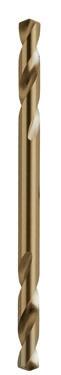
Technical Information
Technical Information
Technical Information
Technical Information
Technical Information
Technical Information Shank Designs - HSS Tools
Technical Information
Technical Information Tapping Drill Size Chart
Technical Information Tapping Drill Size Chart (Fluteless)
Technical Information Tapping Information
Technical Information
Technical Information
Technical Information
Technical Information
Technical Information
Technical Information
3 Drills Jobber Sets – Imperial Reamers Finder 143 Reamers Adjustable 154 Reamers Bridge 150 Reamers Chucking 149 Reamers Hand 144 Reamers Machine 146 Reamers Morse Taper Socket 152 Reamers Taper Pin 151 Reamers Taper Pipe 153
Burrs Finder 158
Carbide
Ball Shape 164
Cone Shape 174
Cylindrical, Radius End 162
Cylindrical, Square End 160
Die Grinder Kit 177
Flame Shape 171
Inverted Cone Shape 175
Oval Shape 166
Sets 176
Taper Shape 172
Carbide Burrs
Tree Shape, Pointed End 170
Tree Shape, Radius End 168 Others Finder 180 Other Black Books 180 Other Cutting Lubricant, Venom 181 Technical Information Index 185
Materials - Workpiece 186
Carbide Burrs
Application Guide
Speeds & Feeds - HSS Drills 190
Speeds & Feeds - HSS Endmills 194
Speeds & Feeds - Taps 192
Application Guide
Application Guide
Troubleshooting - Drills 196
Endmills 198
Application Guide Troubleshooting -
Troubleshooting - Reamers 199
Troubleshooting - Taps 197 Enquiry - Carbide Drills 229 Enquiry - HSS Drills 228 Enquiry - Milling 230 Enquiry - Taps 227 Technical Information British Standard Threads 222
Coatings & Surface Finish 200
Conversion Tables 202
Drill Terminology 207 Technical Information Endmills - Types 225 Technical Information Endmill Terminology 224
Fluteless Taps 216
Application Guide
Technical Information
Technical Information
Technical Information
Technical Information
Hints on Use
Maintenance 208
&
ISO Metric Tap
220
Class & Tolerance
ISO
Tap
223
Pipe
Thread Systems
Manufacturing Tolerances 204
Materials - Tool 201
Reamers 226
Technical Information
206
Shank Designs - Carbide Tools
205
Tap
212
Geometry
214
217
213
210
Taps
Tap
209
Terminology
Tensile Strength
204
vs Hardness (≈)
Thread
Components
218
Forms
& Tap Limits
Thread Limits 219
Unified
221 Contents Contents
Screw Thread Tolerancing System
4 Drills Jobber Sets – Imperial * Not available once current stock is depleted
Catalogue Code Page No. Discount Group Geometry Description Point Type Tool Material Surface Finish Shank B200 160 B0102 Double Cut Carbide Burrs, Cylindrical Square End VHM Brt 1/4" B201 162 B0102 Double Cut Carbide Burrs, Cylindrical Radius End VHM Brt 1/4" B202 164 B0102 Double Cut Carbide Burrs, Ball Shape VHM Brt 1/4" B203 166 B0102 Double Cut Carbide Burrs, Oval Shape VHM Brt 1/4" B204 168 B0102 Double Cut Carbide Burrs, Tree Shape Radius End VHM Brt 1/4" B205 170 B0102 Double Cut Carbide Burrs, Tree Shape Pointed End VHM Brt 1/4" B206 171 B0102 Double Cut Carbide Burrs, Flame Shape VHM Brt 1/4" B207 172 B0102 Double Cut Carbide Burrs, Taper Shape VHM Brt 1/4" B208 174 B0102 Double Cut Carbide Burrs, Cone Shape VHM Brt 1/4" B209 175 B0102 Double Cut Carbide Burrs, Inverted Cone Shape VHM Brt 1/4" B210 160 B0102 Double Cut Carbide Burrs, Cylindrical, Long Reach Square End VHM Brt 1/4" B211 162 B0102 Double Cut Carbide Burrs, Cylindrical, Long Reach Radius End VHM Brt 1/4" B212 164 B0102 Double Cut Carbide Burrs, Ball Shape, Long Reach VHM Brt 1/4" B213 168 B0102 Double Cut Carbide Burrs, Tree Shape, Long Reach Radius End VHM Brt 1/4" B214 172 B0102 Double Cut Carbide Burrs,
Shape, Long Reach VHM Brt 1/4" B215 160 B0102 Al Cut Carbide Burrs, Cylindrical Square End VHM Brt 1/4" B216 162 B0102 Al Cut Carbide Burrs,
Radius End VHM Brt 1/4" B217 164 B0102 Al Cut Carbide Burrs, Ball Shape VHM Brt 1/4" B218 166 B0102 Al Cut Carbide Burrs, Oval Shape VHM Brt 1/4" B219
Cut Carbide Burrs, Tree Shape Radius End VHM Brt 1/4" B220 172 B0102 Al Cut Carbide Burrs, Taper Shape VHM Brt 1/4” B300 161 B0102 Double Cut Carbide Burrs, Cylindrical Square End VHM Brt 6mm B301 163 B0102 Double Cut Carbide Burrs, Cylindrical Radius End VHM Brt 6mm B302 165 B0102 Double Cut Carbide Burrs, Ball Shape VHM Brt 6mm B303 167 B0102 Double Cut Carbide Burrs, Oval Shape VHM Brt 6mm B304 169 B0102 Double Cut Carbide Burrs, Tree Shape Radius End VHM Brt 6mm B305 170 B0102 Double Cut Carbide Burrs, Tree Shape Pointed End VHM Brt 6mm B306 171 B0102 Double Cut Carbide Burrs, Flame Shape VHM Brt 6mm B307 173 B0102 Double Cut Carbide Burrs, Taper Shape VHM Brt 6mm B308 174 B0102 Double Cut Carbide Burrs, Cone Shape VHM Brt 6mm B315 161 B0102 Al Cut Carbide Burrs, Cylindrical Square End VHM Brt 6mm B316 163 B0102 Al Cut Carbide Burrs, Cylindrical Radius End VHM Brt 6mm B317 165 B0102 Al Cut Carbide Burrs, Ball Shape VHM Brt 6mm B319 169 B0102 Al Cut Carbide Burrs, Tree Shape Radius End VHM Brt 6mm B900 176 B0102 Carbide Burrs, Sets VHM Brt 1/4" B902 177 B0102 - Carbide Burrs, Die Grinder Kit - - -Countersinks Catalogue Code Page No. Discount Group Description Point Type Tool Material Surface Finish Standard C100 64 B0709 Counterbore - HSS Co Brt DIN373 C101 62 A1106 Deburring Countersink, Cross Hole 90° HSS Brt Sutton C102 62 A1108 Deburring Countersink, Cross Hole 90° HSS TiN Sutton C103 61 A1106 Countersink, Single Flute 90° HSS Brt Sutton C104 61 A1108 Countersink, Single Flute 90° HSS TiN Sutton C105 60 A1106 Countersink, Three Flute 90° HSS Brt Sutton C106 60 A1108 Countersink, Three Flute 90° HSS TiN Sutton C107 63 A1106 Countersink, Three Flute, N 90° HSS Co Brt DIN335 C108 63 A1108 Countersink, Three Flute, UNI 90° HSS Co TiAlN DIN335 Product Index Contents
Carbide Burrs
Taper
Cylindrical
168 B0102 Al
5
Imperial * Not available once current stock is depleted Drills Catalogue Code Page No. Discount Group Description Point Type Tool Material Surface Finish Standard D101 15 A1202 Drill, Jobber, Silver Bullet, Metric Sets 118° Standard HSS Brt DIN338 D101 17 A1202 Drill, Jobber, Silver Bullet, Imperial Sets 118° Standard HSS Brt DIN338 D101 18 A0402 Drill, Jobber, Silver Bullet 118° Standard HSS Brt DIN338 D102 15 A1202 Drill, Jobber, Blue Bullet, Metric Sets 118° Standard HSS Blu DIN338 D102 17 A1202 Drill, Jobber, Blue Bullet, Imperial Sets 118° Standard HSS Blu DIN338 D102 18 A0402 Drill, Jobber, Blue Bullet 118° Standard HSS Blu DIN338 D103 15 A1216 Drill, Jobber, TiNite, Metric Sets 118° Form A HSS TiN DIN338 D103 17 A1216 Drill, Jobber, TiNite, Imperial Sets 118° Form A HSS TiN DIN338 D103 26 A0420 Drill, Jobber, TiNite 118° Form A HSS TiN DIN338 D105 15 A1202 Drill, Jobber, Viper, Bright, Metric Sets 118° Form C HSS Brt DIN338 D105 17 A1202 Drill, Jobber, Viper, Bright, Imperial Sets 118° Form C HSS Brt DIN338 D109 15 A0404 Drill, Jobber, Cobalt Heavy Duty, Metric Sets 135° Form C HSS Co Colour Temp DIN338 D109 17 A0404 Drill, Jobber, Cobalt Heavy Duty, Imperial Sets 135° Form C HSS Co Colour Temp DIN338 D109 31 A0404 Drill, Jobber, Cobalt Heavy Duty 135° Form C HSS Co Colour Temp DIN338 D113 39 A0502 Drill, Long Series 118° Standard HSS Blu ANSI B94-11 D115 43 A0702 Drill, Morse Taper Shank 118° Form A HSS Blu DIN345 D118 48 A0702 Morse Taper Sleeve - Alloy BrtD121 50 A0802 Drill, Panel, Single Ended 135° Standard HSS BrtD122 50 A0802 Drill, Panel, Double Ended 135° Standard HSS BrtD123 50 A1002 Drill, Panel, Stub 118° Standard HSS BrtD124 50 A0802 Drill, Panel, Single Ended 135° Standard HSS BluD125 50 A0802 Drill, Panel, Double Ended 135° Standard HSS BluD126 38 A1002 Drill, Stub, Blu 118° Form C HSS Blu ANSI B94-11 D130 51 A0802 Drill, Panel, Double Ended 135° Standard HSS Co Colour TempD135 52 A0302 Drill, Centre, A-Type 60° Stepped HSS Brt DIN333 D136 52 A0302 Drill, Centre, Plain Type 60° Stepped HSS Brt ANSI B94-11 D140 47 A0702 Drill, Morse Taper Shank, Long Series 118° Standard HSS Blu DIN 341 D141 46 A0702 Drill, Morse Taper Shank, Heavy Duty 118° Form A HSS Co Colour Temp DIN345 D142 48 A0702 Drill, Morse Drill, Drift Key - - -D175 53 A1124 Drill, NC Spotting 90° HSS Co TiN DIN1897 D176 53 A1124 Drill, NC Spotting 120° HSS Co TiN DIN1897 D179 15 A1202 Drill, Jobber, Viper Plus, Metric Sets 118° Form C HSS TiAlN Tip DIN338 D179 17 A1202 Drill, Jobber, Viper Plus, Imperial Sets 118° Form C HSS TiAlN Tip DIN338 D179 26 A0402 Drill, Jobber, Viper Plus 118° Form C HSS TiAlN Tip DIN338 D180 15 A1202 Drill, Jobber, R40 InOx, Metric Sets 130° HSS TiAlN Tip ~DIN338 D180 34 A0402 Drill, Jobber, R40 InOx 130° HSS TiAlN Tip ~DIN338 D186 36 A1002 Drill, Stub, Blu 118° Form C HSS Blu DIN1897
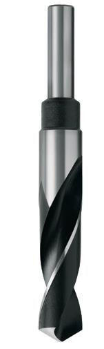
49 A0906 Drill, Reduced Shank, 12.5mm 118° Standard HSS Blu -
33 A0404 Drill, Jobber, Left Hand Cobalt 118° Standard HSS Co Colour Temp DIN338 Product Index Contents
Drills Jobber Sets –
D188
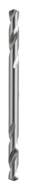
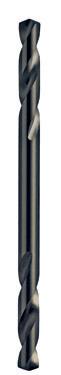
D202
Endmills
E100 125 B0502 Slot Drill, 2 Flute, R30 N, Stub
E102 127 B0502 Slot Drill, 2 Flute, R30 N, Long
E113 137 B0502 Slot Drill, Ballnose, 2 Flute, R30 N, Long Reach
E125 129 B0502 Endmill, 4 Flute, R30 N, Regular
E127 132 B0502 Endmill, 4 Flute, R30 N, Long
E142 134 B0402 Rougher, NR (normal), R30 WN, Regular
E143 135 B0404 Rougher, NR (normal), R30 WN, Regular
E144 134 B0402 Rougher, NR (normal), R30 WN, Regular
E146 136 B0402 Rougher, NR (normal), R30 WN, Long
E168 138 B0402 Rougher, HR (fine) R30 NH, Regular
E169 138 B0404 Rougher, HR (fine) R30 NH, Regular
E178 124 B0709 Rougher, Woodruff Cutter, Threaded
E184 128 B0608 Slot Drill, 2 Flute, R30 N, Long
E192 131 B0608 Endmill, 4 Flute, R30 N, Regular
E225 127 B0502 Slot Drill, 2 Flute, R30 N, Long
E227 129 B0502 Endmill, 4 Flute, R30 N, Regular
E229 132 B0502 Endmill, 4 Flute, R30 N, Long
E230 133 B0516 Endmill, 4 Flute, R30 N, Long
DIN844L
JIS
1835-A HSS Co.8 TiCN JIS
6 Drills Jobber Sets – Imperial
Catalogue Code Page No. Discount Group Description Shank Tool Material Surface Finish Standard
DIN 1835-A HSS Co.8 Brt
JIS
DIN 1835-A HSS Co.8 Brt
JIS
DIN 1835-A HSS Co.8 Brt Sutton
DIN 1835-A HSS Co.8 Brt
JIS
DIN
HSS Co.8 Brt
1835-A
JIS
DIN 1835-A HSS Co.8 Brt
JIS
DIN 1835-A HSS Co.8 TiCN
JIS
DIN
HSS Co.8
1835-B
Brt JIS
DIN
HSS Co.8 Brt
1835-A
DIN 1835-A HSS Co.8 Brt
DIN
DIN 1835-D HSS Brt Sutton
DIN 1835-A HSS Co.8 TiAlN DIN844L
DIN 1835-A HSS Co.8 TiAlN DIN844K
DIN
HSS Co.8
1835-A
Brt JIS
DIN 1835-A HSS Co.8 Brt JIS
DIN
HSS Co.8 Brt
1835-A
JIS
DIN 1835-A HSS Co.8 TiCN JIS Literature
Catalogue Code Page No. Discount Group Description Geometry Tool Material Surface Finish Standard L100 180 Z0502 Engineers Black Book - - -L103 180 Z0502 Engineers Black Book - Large Edition - - -L200 180 Z0502 Fasteners Black Book - - -L203 180 Z0502 Fasteners Black Book - Large Edition - - -L300 180 Z0502 Electrical Black Book - - -M300 55 Z0802 Tool Bit Round M2 HSS BrtM301 54 Z0802 Tool Bit Square M2 HSS BrtM302 54 Z0802 Tool Bit Square M42 CoHSS BrtM304* 55 Z0802 Tool Bit Bevel M35 CoHSS BrtM800 181 Z1006 Cutting Lubricant, Venom - - -Reamers Catalogue Code Page No. Discount Group Description Geometry Tool Material Surface Finish Standard R100 144 B0302 Reamer, Hand 10° Left Helix HSS Brt DIN206 / ISO 236 R101 146 B0302 Reamer, Machine 10° Left Helix HSS Brt DIN208 R102 149 B0302 Reamer, Chucking 10° Left Helix HSS Co Brt DIN212 / ISO 521 R104 150 B0302 Reamer, Bridge 15° Left Helix HSS Brt Sutton R105 151 B0302 Reamer, Taper Pin 7° Left Helix HSS Brt Sutton R106 152 B0302 Reamer, Morse Taper Socket, Roughing 7° Left Helix HSS Brt Sutton R107 152 B0302 Reamer, Morse Taper Socket, Finishing 7° Left Helix HSS Brt Sutton R108 153 B0302 Reamer, Taper Pipe 15° Left Helix HSS Brt Sutton R109 154 B0304 Reamer, Adjustable Straight TCA Brt Sutton R110 154 B0304 Reamer, Adjustable, Blade - TCA BrtR111 155 B0304 Reamer, Adjustable, Pilot - TCA BrtR112 155 B0304 Reamer, Adjustable, Nut - TCA BrtProduct Index * Not available once current stock is depleted Contents
& Miscellaneous
Taps
D0702 Tap, Straight Flute, N, Left Hand
T420 84 D0702 Tap, Straight Flute, N, Left Hand
T421 85 D0702 Tap, Straight Flute, N, Left Hand
87 D0706 Tap, Gun, N
T425 88 D0702 Tap, Spiral Flute, N
T426 88 D0702 Tap, Spiral Flute, N
T427 89 D0706 Tap, Spiral Flute, N
T428 90 D0702 Tap, Forming, with single coolant groove
T430 91 D0702 Tap, Machine Nut, Long Shank
T431 92 D0702 Tap, Straight Flute, N
T432 92 D0702 Tap, Straight Flute, N
T433 93 D0702 Tap, Straight Flute, N
T436 94 D0702 Tap, Straight Flute, N, Left Hand
T437 94 D0702 Tap, Straight Flute, N, Left Hand
T438 95 D0702 Tap, Straight Flute, N, Left Hand
T439 98 D0702 Tap, Gun, N
T440 98 D0702 Tap, Gun, N
T441 99 D0706 Tap, Gun, N
T442 100 D0702 Tap, Spiral Flute, N
T443 100 D0706 Tap, Spiral Flute, N
7 Drills Jobber
– Imperial
Sets
Catalogue Code Page No. Discount Group Description Thread Geometry Type Tool Material Surface Finish Standard T384 68 D0702 Tap, Straight Flute, N M Taper HSS Brt ISO529 T385 68 D0702 Tap, Straight Flute, N M Intermediate HSS Brt ISO529 T386 69 D0702 Tap, Straight Flute, N M Bottoming HSS Brt ISO529 T389 70 D0702 Tap, Straight Flute, N, Left Hand M Taper HSS Brt ISO529 T390 70 D0702 Tap, Straight Flute, N, Left Hand M Intermediate HSS Brt ISO529 T391 71 D0702 Tap, Straight Flute, N, Left Hand M Bottoming HSS Brt ISO529 T392 71 D0702 Tap, Straight Flute, N, Oversize M Bottoming HSS Brt ISO529 T393 72 D0702 Tap, Gun, N M Intermediate HSSE Brt ISO529 T394 72 D0702 Tap, Gun, N M Intermediate HSSE Blu ISO529 T395 73 D0706 Tap, Gun, N M Intermediate HSSE TiN ISO529 T396 74 D0702 Tap, Spiral Flute, N M Bottoming HSSE Blu ISO529 T397 74 D0702 Tap, Spiral Flute, N M Bottoming HSSE Brt ISO529 T398 75 D0706
Spiral Flute,
M Bottoming HSSE TiN ISO529 T399 76 D0702
single coolant groove M Short HSSE Brt ISO529 T400
single coolant groove M Short HSSE TiN ISO529 T401 77 D0702 Tap, Straight Flute, N MF Taper HSS Brt ISO529 T402 77 D0702 Tap, Straight Flute, N MF Intermediate HSS Brt ISO529 T403 78 D0702 Tap, Straight Flute, N MF Bottoming HSS Brt ISO529 T406 79 D0702 Tap, Gun, N MF Intermediate HSSE Brt ISO529 T407 79 D0702 Tap, Gun, N MF Intermediate HSSE Blu ISO529 T408 80 D0706 Tap, Gun, N MF Intermediate HSSE TiN ISO529 T409 81 D0702 Tap, Spiral Flute, N MF Bottoming HSSE Brt ISO529 T411 81 D0706 Tap, Spiral Flute, N MF Bottoming HSSE TiN ISO529 T414 82 D0702 Tap, Straight Flute, N UNC Taper HSS Brt ISO529 T415 82 D0702 Tap, Straight Flute, N UNC Intermediate HSS Brt ISO529 T416 83 D0702 Tap, Straight Flute, N UNC Bottoming HSS Brt ISO529 T419
UNC Taper HSS Brt ISO529
UNC Intermediate HSS Brt ISO529
UNC
HSS Brt ISO529
UNC Intermediate HSSE Brt ISO529 T423
UNC Intermediate HSSE Blu ISO529 T424
UNC Intermediate HSSE TiN ISO529
Tap,
N
Tap, Forming, with
76 D0706 Tap, Forming, with
84
Bottoming
T422 86 D0702 Tap, Gun, N
86 D0702 Tap, Gun, N
UNC Bottoming HSSE Brt ISO529
UNC Bottoming HSSE Blu ISO529
UNC
HSSE TiN ISO529
Bottoming
UNC Short HSSE Brt ISO529
UNC Short HSSE TiN ISO529
UNC Bottoming HSS Brt BS 949
UNF Taper HSS Brt ISO529
UNF Intermediate HSS Brt ISO529
T429 90 D0706 Tap, Forming, with single coolant groove
UNF Bottoming HSS Brt ISO529
UNF
Brt ISO529
Taper HSS
UNF Intermediate HSS Brt ISO529
UNF Bottoming HSS Brt ISO529
UNF Intermediate HSSE Brt ISO529
UNF Intermediate HSSE Blu ISO529
UNF Intermediate HSSE TiN ISO529
UNF
ISO529
Bottoming HSSE Brt
UNF
TiN ISO529 Product Index * Not available once current stock is depleted Contents
Bottoming HSSE
Taps (Continued)
101
Tap, Forming, with single coolant groove
T445 96 D0702 Tap, Straight Flute, N
T446 96 D0702 Tap, Straight Flute, N
T447 97 D0702 Tap, Straight Flute, N
102 D0702 Tap, Straight Flute, N
102 D0702 Tap, Straight Flute, N
T450 103 D0702 Tap, Straight Flute, N
104 D0702 Tap, Straight Flute, N
T452 104 D0702 Tap, Straight Flute, N
105 D0702 Tap, Straight Flute, N
106 D0702 Tap, Straight Flute, N, Left Hand
T457 107 D0702 Tap, Gun, N
T458 107 D0702 Tap, Gun, N
T459 108 D0706 Tap, Gun, N
T460 109 D0702 Tap, Spiral Flute, N
T461 109 D0702 Tap, Spiral Flute, N
T462 110 D0706 Tap, Spiral Flute, N
T463 111 D0702 Tap, Forming, with single coolant groove
T464 111 D0706 Tap, Forming, with single coolant groove
T465 112 D0702 Tap, Machine Nut, Long Shank
113
N
113 D0702 Tap, Straight Flute, N
114 D0702 Tap, Straight Flute, N
113 D0702 Tap, Straight Flute, N
113 D0702 Tap, Straight Flute, N
114
113
N
113 D0702 Tap, Straight Flute, N
T474 114 D0702 Tap, Straight Flute, N
T475 118 D0702 Tap, Straight Flute, Pipe
T476 118
118
118
115
115 D0702 Tap, Straight Flute, Pipe
8 Drills Jobber Sets – Imperial
Catalogue Code Page No. Discount Group Description Thread Geometry Type Tool Material Surface Finish Standard T444
UNF Short HSSE Brt ISO529
UNEF Taper HSS Brt ISO529
UNEF Intermediate HSS Brt ISO529
UNEF Bottoming HSS Brt ISO529 T448
8UN Taper HSS Brt ISO529 T449
8UN Intermediate HSS Brt ISO529
8UN Bottoming HSS Brt ISO529
BSW Taper HSS Brt ISO529
BSW Intermediate HSS Brt ISO529 T453
BSW Bottoming HSS Brt ISO529 T456
BSW Bottoming HSS Brt ISO529
D0702
T451
BSW Intermediate HSSE Brt ISO529
BSW Intermediate HSSE Blu ISO529
BSW Intermediate HSSE TiN ISO529
BSW Bottoming HSSE Brt ISO529
BSW Bottoming HSSE Blu ISO529
BSW
Bottoming HSSE TiN ISO529
BSW
ISO529
BSW
ISO529
Short HSSE Brt
Short HSSE TiN
BSW Bottoming HSS Brt BS 949 T466
BSF Taper HSS Brt ISO529 T467
BSF Intermediate HSS Brt ISO529
BSF Bottoming HSS Brt ISO529
BA Taper HSS Brt ISO529
BA Intermediate
ISO529 T471
D0702
BA Bottoming HSS Brt ISO529 T472
D0702
BSB Taper HSS Brt ISO529 T473
BSB Intermediate HSS Brt ISO529
BSB Bottoming HSS Brt ISO529
Rc
HSS
ISO2284
D0706
Rc (BSPT) Bottoming HSS TiN ISO2284 T477
D0702
Rp (BSPPL) Bottoming HSS Brt ISO2284
Pg Bottoming HSS Brt ISO529 T479
D0702
G (BSPF) Taper HSS Brt ISO2284
G (BSPF) Intermediate HSS Brt ISO2284 T481
D0702 Tap, Straight Flute, Pipe G (BSPF) Bottoming HSS Brt ISO2284 T482 117 D0706 Tap, Straight Flute, Pipe G (BSPF) Intermediate HSS TiN ISO2284 T483 117 D0706 Tap, Straight Flute, Pipe G (BSPF) Bottoming HSS TiN ISO2284 T484 115 D0702 Tap, Gun, Pipe G (BSPF) Intermediate HSS Brt ISO529 T485 116 D0702 Tap, Spiral Flute, Pipe G (BSPF) Bottoming HSS Brt ISO529 T486 119 D0702 Tap, Straight Flute, Pipe NPSF Bottoming HSS Colour Temp ANSI B94-9 T487 119 D0702 Tap, Straight Flute, Pipe NPT Bottoming HSS Colour Temp ANSI B94-9 T488 119 D0702 Tap, Straight Flute, Pipe NPTF Bottoming HSS Colour Temp ANSI B94-9 T489 97 D0702 Tap, Straight Flute, Tyre Valve UNS Bottoming HSS Brt ISO529 T490 97 D0702 Tap, Straight Flute, Stitching Stitching Bottoming HSS Brt ISO529 T637 76 D0702 Tap, Forming, with single coolant groove MF Short HSSE Brt ISO529 T901 69 D0702 Set, Tap, 3 piece M Taper/Inter/Bott HSS Brt ISO529 T902 78 D0702 Set, Tap, 3 piece MF Taper/Inter/Bott HSS Brt ISO529 T903 83 D0702 Set, Tap, 3 piece UNC Taper/Inter/Bott HSS Brt ISO529 T904 93 D0702 Set, Tap, 3 piece UNF Taper/Inter/Bott HSS Brt ISO529 T905 105 D0702 Set, Tap, 3 piece BSW Taper/Inter/Bott HSS Brt ISO529 T906 114 D0702 Set, Tap, 3 piece BSF Taper/Inter/Bott HSS Brt ISO529 T907 114 D0702 Set, Tap, 3 piece BA Taper/Inter/Bott HSS Brt ISO529 T908 114 D0702 Set, Tap, 3 piece BSB Taper/Inter/Bott HSS Brt ISO529 T909 116 D0702 Set, Tap, 3 piece G (BSPF) Taper/Inter/Bott HSS Brt ISO2284 T910 103 D0702 Set, Tap, 3 piece 8UN Taper/Inter/Bott HSS Brt ISO529 Product Index * Not available once current stock is depleted Contents
D0702 Tap, Straight Flute,
T468
T469
T470
HSS Brt
Tap, Straight Flute,
Tap, Straight Flute, N
(BSPT) Bottoming
Brt
Tap, Straight Flute, Pipe
Tap, Straight Flute, Pipe
T478
D0702 Tap, Straight Flute, Pipe
Tap, Straight Flute, Pipe
T480
116
be determined by referring to the material cross reference listing in the application guide at the back of this catalogue.
for general purpose for universal materials for aluminiums for soft materials for copper materials for tough materials for cast iron materials for hard materials for extra
materials for very hard materials for titaniums for nickels
9 Drills Jobber Sets – Imperial Application Guide
N UNI AI W Cu VA GG H XH VH Ti Ni ISO VDI^ 3323 Material Condition HB N/mm2 P 1 Steel - Non-alloy, cast & free cutting ~ 0.15 %C A 125 440 • • • • 2 ~ 0.45 %C A 190 640 • • • • 3 QT 250 840 • • • • • 4 ~ 0.75 %C A 270 910 • • • • • 5 QT 300 1010 • • • 6 Steel - Low alloy & cast < 5% of alloying elements A 180 610 • • • • 7 QT 275 930 • • • • • 8 QT 300 1010 • • • 9 QT 350 1180 • • • • 10 Steel - High alloy, cast & tool A 200 680 • • • • 11 HT 325 1100 • • • • 12 Steel - Corrosion resistant & cast Ferritic / Martensitic A 200 680 • • • 13 Martensitic QT 240 810 • • • • • M 14.1 Stainless Steel Austenitic AH 180 610 • • 14.2 Duplex 250 840 • • • 14.3 Precipitation Hardening 250 840 • • • • K 15 Cast Iron - Grey (GG) Ferritic / Pearlitic 180 610 • • • • 16 Pearlitic 260 880 • • • • 17 Cast Iron - Nodular (GGG) Ferritic 160 570 • • • • 18 Pearlitic 250 840 • • • • 19 Cast Iron - Malleable Ferritic 130 460 • • • • 20 Pearlitic 230 780 • • • • N 21 Aluminum & Magnesium - wrought alloy Non Heat Treatable 60 210 • • • • • • 22 Heat Treatable AH 100 360 • • • • • • 23 Aluminum & Magnesium - cast alloy ≤12% Si Non Heat Treatable 75 270 • • • • • • 24 Heat Treatable AH 90 320 • • • • • • 25 Al & Mg - cast alloy >12% Si Non Heat Treatable 130 460 • • • • • • 26 Copper & Cu alloys (Brass/Bronze) Free cutting, Pb > 1% 110 390 • • • • • • 27 Brass (CuZn, CuSnZn) 90 320 • • • • • • • • 28 Bronze (CuSn) 100 360 • • • • • 29 Non-metallic - Thermosetting & fiber-reinforced plastics • 30 Non-metallic - Hard rubber, wood etc. S 31 High temp. alloys Fe based A 200 680 • • 32 AH 280 950 • • 33 Ni / Co based A 250 840 • • • 34 AH 350 1180 • 35 C 320 1080 • 36 Titanium & Ti alloys CP Titanium 400 MPa • 37.1 Alpha alloys 860 MPa • • 37.2 Alpha / Beta alloys A 960 MPa • 37.3 AH 1170 MPa • 37.4 Beta alloys A 830 MPa • 37.5 AH 1400 MPa • H 38.1 Hardened steel HT 45 HRC • • • • 38.2 HT 55 HRC • 39.1 HT 58 HRC • 39.2 HT 62 HRC • 40 Cast Iron Chilled C 400 1350 • • • • • 41 HT 55 HRC • Condition: A (Annealed), AH (Age Hardened), C (Cast), HT (Hardened & Tempered), QT (Quenched & Tempered) ISO VDI Material Group Sutton
A Steel N UNI M R Stainless Steel VA K F Cast Iron GG
N Non-Ferrous Metals, Aluminiums & Coppers AI W
S Titaniums & Super Alloys Ti Ni
H Hard Materials (≥ 45 HRC) H
VDI 3323 material groups can
• Optimal • Effective Contents
hard
P
N
S
H
^
also
10 Contents
DRILLS
•
•
•
•
•
Bits
Stub Series
Jobber Series
Long Series
Spotting
Tool
be determined by referring to the material cross reference listing in the application guide at the back of this catalogue.
expert tooling recommendations, go to: www.suttonhps.com
12 Page 18 18 26 26 31 33 34 36 38 41 Catalogue Code D101 D102 D103 D179 D109 D202 D180 D186 D126 D113 Material HSS HSS Co HSS Co HSS HSS HSS HSS Surface Finish Brt Blu TiN TiAlN Tip Colour Tmp Colour Tmp TiAlN Tip Blu Blu Blu Sutton Designation N Hard Mat. N VA N N N Standard DIN 338 DIN 338 DIN 338 ~ DIN 338 DIN 1897 ANSI B94-11 ANSI B94-11 Depth of Cut ≤ 5xØ ≤ 5xØ ≤ 5xØ ≤ 3xØ ≤ 3xØ ≤ 3xØ 8xØ Shank Tolerance h9 - - h9 - - h9 ISO VDI^ 3323 Material Condition HB N/mm2 P 1 Steel - Non-alloy, cast & free cutting ~ 0.15 %C A 125 440 • • • • • • • • • 2 ~ 0.45 %C A 190 640 • • • • • • • • • 3 QT 250 840 • • • • • • • • • • 4 ~ 0.75 %C A 270 910 • • • • • • • • • • 5 QT 300 1010 • • • • • • 6 Steel - Low alloy & cast < 5% of alloying elements A 180 610 • • • • • • • • • 7 QT 275 930 • • • • • • • • • • 8 QT 300 1010 • • • • • • 9 QT 350 1180 • • • • 10 Steel - High alloy, cast & tool A 200 680 • • • • • • • • • 11 HT 325 1100 • • • • 12 Steel - Corrosion resistant & cast Ferritic / Martensitic A 200 680 • • • 13 Martensitic QT 240 810 • • • • M 14.1 Stainless Steel Austenitic AH 180 610 • • • • • • • • 14.2 Duplex 250 840 • • • • • • • 14.3 Precipitation Hardening 250 840 • • K 15 Cast Iron - Grey (GG) Ferritic / Pearlitic 180 610 • • • • • • • • • 16 Pearlitic 260 880 • • • • • • • 17 Cast Iron - Nodular (GGG) Ferritic 160 570 • • • • • • • • • 18 Pearlitic 250 840 • • • • • • • 19 Cast Iron - Malleable Ferritic 130 460 • • • • • • • 20 Pearlitic 230 780 • • • • • • • N 21 Aluminum & Magnesium - wrought alloy Non Heat Treatable 60 210 • • • • • • • 22 Heat Treatable AH 100 360 • • • • • • • 23 Aluminum & Magnesium - cast alloy ≤12% Si Non Heat Treatable 75 270 • • • • • 24 Heat Treatable AH 90 320 • • • • • 25 Al & Mg - cast alloy >12% Si Non Heat Treatable 130 460 • • • • 26 Copper & Cu alloys (Brass/Bronze) Free cutting, Pb > 1% 110 390 • • • • • 27 Brass (CuZn, CuSnZn) 90 320 • • • • • 28 Bronze (CuSn) 100 360 • • • • • 29 Non-metallic - Thermosetting & fiber-reinforced plastics • • • • • • • • 30 Non-metallic - Hard rubber, wood etc. S 31 High temp. alloys Fe based A 200 680 32 AH 280 950 33 Ni / Co based A 250 840 34 AH 350 1180 35 C 320 1080 36 Titanium & Ti alloys CP Titanium 400 MPa 37.1 Alpha alloys 860 MPa 37.2 Alpha / Beta alloys A 960 MPa 37.3 AH 1170 MPa 37.4 Beta alloys A 830 MPa 37.5 AH 1400 MPa H 38.1 Hardened steel HT 45 HRC • 38.2 HT 55 HRC 39.1 HT 58 HRC 39.2 HT 62 HRC 40 Cast Iron Chilled C 400 1350 • • • • • • • • • 41 HT 55 HRC Condition: A (Annealed), AH (Age Hardened), C (Cast), HT (Hardened & Tempered), QT (Quenched & Tempered) ISO VDI Material Group Sutton P A Steel N UNI M R Stainless Steel VA K F Cast Iron GG N N Non-Ferrous Metals, Aluminiums & Coppers AI W S S Titaniums & Super Alloys Ti Ni H H Hard Materials (≥ 45 HRC) H ^ VDI 3323
can
• Optimal • Effective Contents Index
material groups
also
For
Drills Finder
13 43 46 47 48 48 49 50 50 50 50 51 52 53 54 54 55 55 D115 D141 D140 D142 D118 D188 D121 D122 D124 D125 D130 D135 D175 M301 M302 M300 M304 HSS HSS Co HSS - Alloy HSS HSS HSS HSS Co HSS HSS Co M2 HSS M42 CoHSS M2 HSS M42 CoHSS Blu Colour Tmp Blu Brt Brt Blu Brt Blu Colour Tmp Brt TiN Brt Brt N Tough Materials N Adaptor N Non Ferrous Ferrous Tough Materials N NC -DIN 345 DIN 345 DIN 341 - Sutton Sutton Standard Sutton Standard Sutton DIN 333 DIN 1897 Sutton Standard Sutton Standard ≤ 5xØ ≤ 5xØ ≤ 8xØ - ≤ 5xØ - - - - - -- - - - - - - - - h9 -VDI^ 3323 ISO • • • • • • • • • • • 1 P • • • • • • • • • • • 2 • • • • • • • • • • • 3 • • • • • • • • • • • 4 • • • • • • 5 • • • • • • • • • • • 6 • • • • • • • • 7 • • • • • • 8 • 9 • • • • • • • • 10 • 11 • • • 12 • • 13 • • • • • • • • • • • 14.1 M • • • • • • • • • • 14.2 • • 14.3 • • • • • • • • • • • 15 K • • • • 16 • • • • • • • • • • • 17 • • • • 18 • • • • • • 19 • • • • • 20 • • • • • • 21 N • • • • • • 22 • • • • • • 23 • • • • • • 24 • 25 • • • • • • 26 • • • 27 • • • • • • 28 • • 29 30 • 31 S • 32 • 33 • 34 35 36 • 37.1 • 37.2 37.3 • 37.4 37.5 • 38.1 H 38.2 39.1 39.2 • • • • • • • • • • 40 41 Condition: A (Annealed), AH (Age Hardened), C (Cast), HT (Hardened & Tempered), QT (Quenched & Tempered) • Optimal • Effective Contents Index
Drills Sets - Metric
14
SM1 D101 SM2 D101 SM3
D101
D101 MTLSM2 D101 MTLSM3
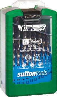
D105 VRKM2
D105 VRKM3
D101 SM7
D103 SM3 D105 SLV7M D105 SLV10M D105 SLV13M D105 V2M D105 V3M
D102 SM99 D102 SM101
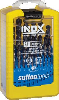
SM2 D109 SM3 D179 SM2 D179 SM3 D180 SM2 D180 SM3
D109
SM1 D102 SM2 D102 SM3
SM8 D102 SM30 D102 SM41 Contents Index
D102
D102
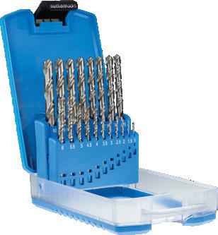
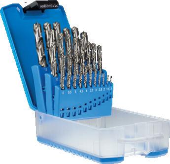
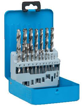
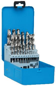
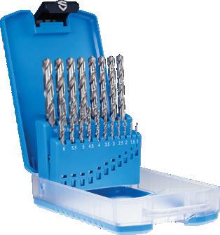
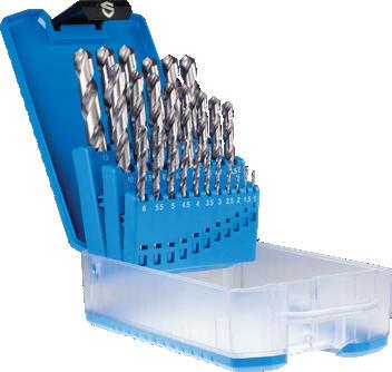
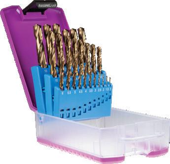
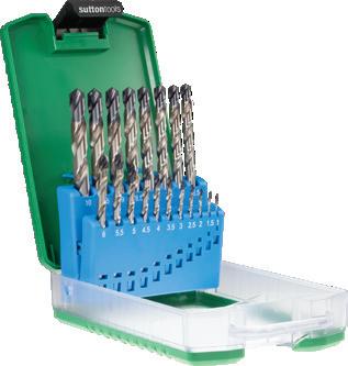
Drills Sets - Metric
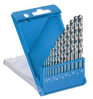
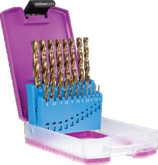
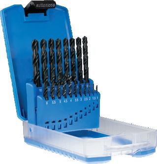
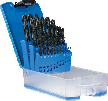
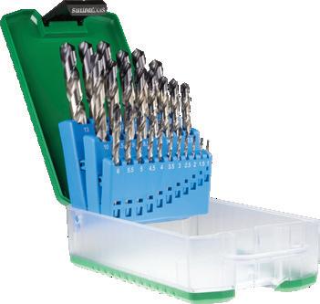
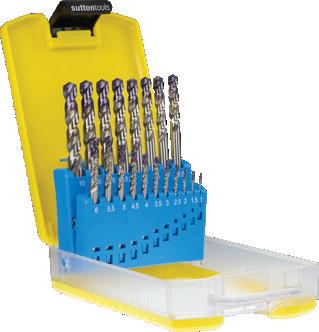
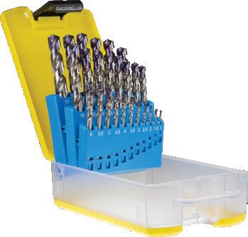
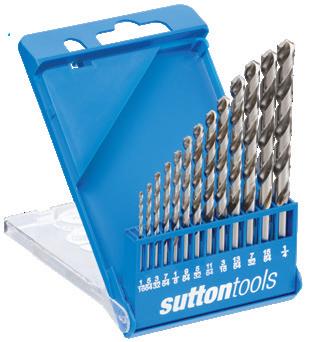
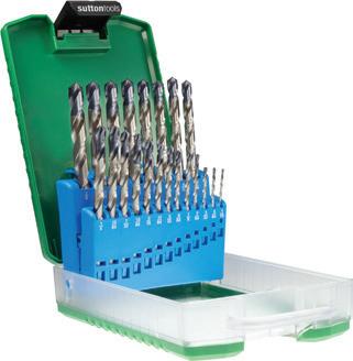
Metric (DIN 338)
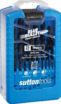
SM1 1.5 – 6.5mm x 0.5mm rises + 3.2, 4.8mm ABS 13
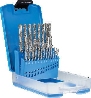
1.0 – 10.0mm x 0.5mm rises ABS 19
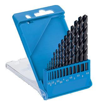
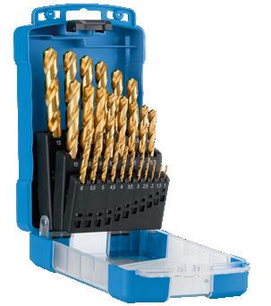
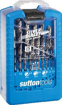
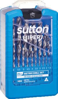
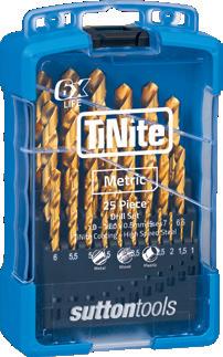
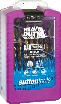
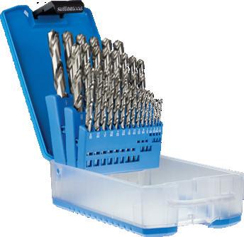
SM3 1.0 – 13.0mm x 0.5mm rises ABS 25
SM8 1.0 – 3.0mm x 0.25mm rises 3.5 – 13.0mm x 0.5mm rises Plastic 29
1.0 – 10.0mm x 0.5mm rises Metal 19
1.0 – 13.0mm x 0.5mm rises Metal 25
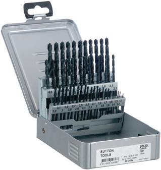
SM30 1.0 – 5.9mm x 0.1mm rises Metal 50
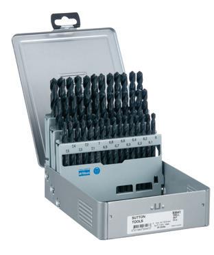
SM41 6.0 – 10.0mm x 0.1mm rises Metal 41 D102 SM41 SM99 1.0 – 10.0mm x 0.1mm rises (+10.5, 10.9, 11.0, 11.5, 11.9, 12.0, 12.5, 12.9, 13.0mm) Plastic 100
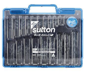
SM101 1.0 – 10.0mm x 0.5mm rises (Plus BONUS Venom Cutting Paste) Plastic 101
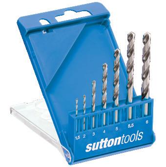
SLV7M 1.5, 2.0, 3.0, 4.0, 5.0, 5.5, 6.0mm Plastic 7
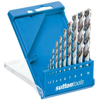
SLV10M 1.0 – 10.0mm x 1.0mm rises Plastic 10
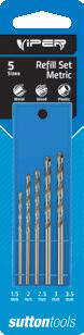
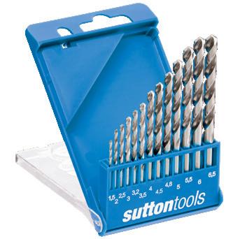
SLV13M 1.5 – 6.5mm x 0.5mm rises + 3.2, 4.8mm Plastic 13
V2M 1.0 – 10.0mm x 0.5mm rises ABS 19
V3M 1.0 – 13.0mm x 0.5mm rises (10.5 – 13.0mm x 10.0mm shanks) ABS 25
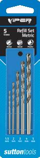
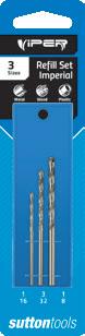
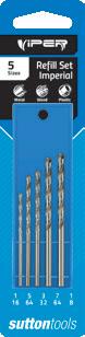
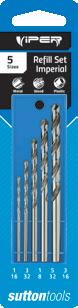
Refill Kits
VRKM2 1.5mm – 3.5mm x 0.5mm rises Tray 5
VRKM3 1.5, 2.0, 3.0, 4.0, 5.0mm Tray 5
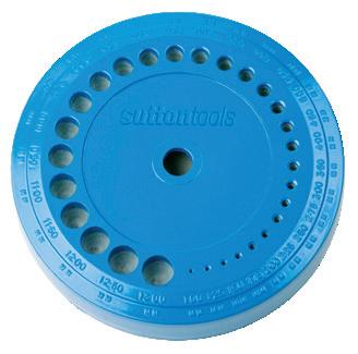
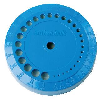
Drill Stands (Discount Group Z0204) SM7 1.0 – 3.0mm x 0.25mm rises 3.5 – 13.0mm x 0.5mm rises Metal 1
15
D101 SM1 D102 SM1
D101 SM2 D102 SM2
D101 SM3 D102
D102
MTLSM2
D101 MTLSM2 MTLSM3
D101 MTLSM3
SM2
SM3
SM8
D102 SM30
D102
SM99
D102
SM101
D105 SLV7M
D105 SLV10M
D105 SLV13M
D105 V2M
D105 V3M
D105 VRKM2
VRKM3
D101 SM7 P Steel M Stainless Steel K Cast Iron N Non-Ferrous Metals S Titanium & Super Alloys H Hard Materials D180 D179 D109 D105 D103 D102 D101 VDI 3323 ISO • • • • • • 1 P • • • • • • 2 • • • • • • • 3 • • • • • • • 4 • • • • 5 • • • • • • 6 • • • • • • • 7 • • • • 8 • • • • 9 • • • • • • 10 • • • • 11 • • • 12 • • • • 13 • • • • • 14.1 M • • • • • 14.2 • • 14.3 • • • • • • 15 K • • • • 16 • • • • • • 17 • • • • 18 • • • • 19 • • • • 20 • • • • 21 N • • • • 22 • • • • • 23 • • • • • 24 • • • • 25 • • • • • 26 • • • • • 27 • • • • • 28 • • • • • • 29 30 31 S 32 33 34 35 36 37.1 37.2 37.3 37.4 37.5 • Optimal • Effective • 38.1 H 38.2 39.1 39.2 • • • • • • 40 41
D105
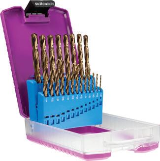
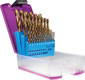
- Various combinations available - Metric and Imperial Catalogue Code D101 D102 D105 Discount Group A1202 A1202 A1202 Material HSS HSS HSS Surface Finish Brt Blu Brt Sutton Designation N N N Geometry R30 R30 R30 Point Type 118° Standard 118° Standard 118° Form C Shank Tolerance - -Size Ref. Range Case Pieces Item # Item # Item # Catalogue Code D103 D109 D179 D180 Discount Group A1216 A0404 A1202 A1202 Material HSS HSS Co HSS HSS Surface Finish TiN Colour Temp TiAIN Tip TiAIN Tip Sutton Designation N Tough Materials N N Geometry R30 R25 R30 R40 Point Type 118° Form A 135° Form C 118° Form C 130° Standard Shank Tolerance - - -Size Ref. Range Case Pieces Item # Item # Item # Item # Metric (DIN 338) SM2 1.0 – 10.0 x 0.5mm rises ABS 19 D109 SM2 D179 SM2 D180 SM2 SM3 1.0 – 13.0 x 0.5mm rises ABS 25 D103 SM3 D109 SM3 D179 SM3 D180 SM3 Contents Index

16 Drills Sets - Imperial
D101 S2
D101 S3
D101 MTLS2*
D101 MTLS3*
D101 S30
D102 S2
D102 S3
D102 S8
D109 S2
D109 S3
D179 S2
D179 S3
D103 S3
D105 SLV7
D105 SLV13
D105 V2
D105 V3
D101 S31
D105 VRK1
D105 VRK2
D105 VRK3
Contents Index
D101 S7
Drills Sets - Imperial
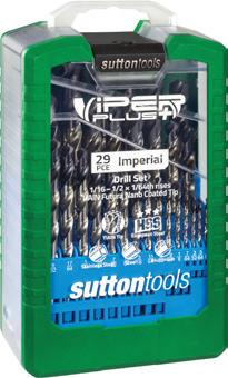
17 DIN 338 S2 1/16 – 3/8 x 1/64 rises ABS 21 D109 S2 D179 S2 S3 1/16 – 1/2 x 1/64 rises ABS 29 D103 S3 D109 S3 D179 S3 DIN 338 S2 1/16 – 3/8 x 1/64 rises ABS 21 D101 S2 D102 S2 S3 1/16 – 1/2 x 1/64 rises ABS 29 D101 S3 D102 S3 S8 1/16 – 1/2 x 1/64 rises Plastic 29 D102 S8 MTLS2 1/16 – 3/8 x 1/64 rises Metal 21 D101 MTLS2* MTLS3 1/16 – 1/2 x 1/64 rises Metal 29 D101 MTLS3* S30 #1 – #60 Wire Gauge Metal 60 D101 S30 S31 #61 – #80 Wire Gauge Plastic 20 D101 S31 SLV7 1/16 – 1/4 x 1/32 rises Plastic 7 D105 SLV7 SLV13 1/16 – 1/4 x 1/64 rises Plastic 13 D105 SLV13 V2 1/16 – 3/8 x 1/64 rises ABS 21 D105 V2 V3 1/16 – 1/2 x 1/64 rises (25/64 – 1/2 x 3/8 shanks) ABS 29 D105 V3 Refill Kits VRK1 1/16, 3/32, 1/8 Tray 3 D105 VRK1 VRK2
1/64 rises Tray 5 D105 VRK2 VRK3 1/16 – 3/16 x 1/32 rises Tray 5 D105 VRK3 Drill Stands (Discount Group Z0204) S7 1/16 – 1/2 x 1/64 rises Metal 1 D101 S7 P Steel M Stainless Steel K Cast Iron N Non-Ferrous Metals S Titanium & Super Alloys H Hard Materials D179 D109 D105 D103 D102 D101 VDI 3323 ISO • • • • • 1 P • • • • • 2 • • • • • • 3 • • • • • • 4 • • • • 5 • • • • • 6 • • • • • • 7 • • • • 8 • • • • 9 • • • • • • 10 • • • • 11 • • 12 • • • 13 • • • • 14.1 M • • • • 14.2 • 14.3 • • • • • • 15 K • • • • 16 • • • • • • 17 • • • • 18 • • • • 19 • • • • 20 • • • 21 N • • • 22 • • • • 23 • • • • 24 • • • • 25 • • • • 26 • • • • • 27 • • • • 28 • • • • • 29 30 31 S 32 33 34 35 36 37.1 37.2 37.3 37.4 37.5 • Optimal • Effective • 38.1 H 38.2 39.1 39.2 • • • • • • 40 41 * Not available once current stock is depleted
1/16 – 1/8 x
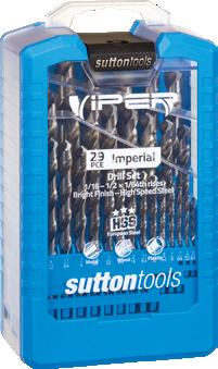
Catalogue Code D101 D102 D105 Discount Group A1202 A1202 A1202 Material HSS HSS HSS Surface Finish Brt Blu Brt Sutton Designation N N N Geometry R30 R30 R30 Point Type 118° Standard 118° Standard 118° Form C Shank Tolerance - -Size Ref. Range Case Pieces Item # Item # Item # Catalogue Code D103 D109 D179 Discount Group A1216 A0404 A1216 Material HSS HSS Co HSS Surface Finish TiN Colour Temp Brt Sutton Designation N Tough Materials N Geometry R30 R25 R30 Point Type 118° Form A 135° Form C 118° Form A Shank Tolerance - -Size Ref. Range Case Pieces Item # Item # Item # - Various combinations available - Metric and Imperial Contents Index
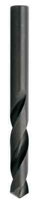
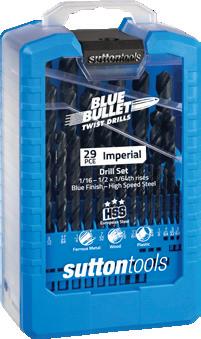
Drills Jobber, Silver & Blue Bullet
18 0034 0.34 80 19 3 D101 0034 • 0035 0.35 19 4 D101 0035 • 0037 0.37 79 19 3 D101 0037 • 0038 0.38 19 4 D101 0038 • 0039 0.40 1/64 19 5 D101 0039 • 0040 0.40 20 5 D101 0040 • 0041 0.41 78 22 5 D101 0041 • 0042 0.42 20 5 D101 0042 • 0045 0.45 20 5 D101 0045 • 0046 0.46 77 22 5 D101 0046 • 0048 0.48 20 5 D101 0048 • 0050 0.50 22 6 D101 0050 • 0051 0.51 76 22 5 D101 0051 • 0052 0.52 22 6 • 0053 0.53 75 25 6 D101 0053 • 0055 0.55 24 7 D101 0055 • 0057 0.57 74 25 6 D101 0057 • 0060 0.60 24 7 D101 0060 • 0061 0.61 73 29 8 D101 0061 • 0063 0.63 72 29 8 D101 0063 • 0065 0.65 26 8 D101 0065 • 0066 0.66 71 32 10 D101 0066 • 0070 0.70 28
D101 0070 • 0071 0.71 70 32 10 D101 0071 • 0074 0.74 69 35 13 D101 0074 • 0075 0.75 28 9 D101 0075 • 0078 0.79 68 35
D101 0078 • 0079 0.79 1/32
D101 0079 • 0080 0.80 30 10 D101 0080 • 0081 0.81 67 35 13 D101 0081 • 0084 0.84 66 35 13 D101 0084 • 0085 0.85 30 10 D101 0085 • 0089 0.89 65 38 16 D101 0089 • 0090 0.90 32 11 D101 0090 • 0091 0.91 64 38 16 D101 0091 • 0094 0.94 63 38 16 D101 0094 • 0095 0.95 32 11 D101 0095 • 0096 0.96 62 38 16 D101 0096 • 0099 0.99 61 41 17 D101 0099 • 0100 1.00 34 12 D101 0100 D102 0100 0102 1.02 60 41 17 D101 0102 • 0104 1.04 59 41 17 D101 0104 • P Steel M Stainless Steel K Cast Iron N Non-Ferrous Metals S Titanium & Super Alloys H Hard Materials D102 D101 VDI 3323 ISO • • 1 P • • 2 • • 3 • • 4 • 5 • • 6 • • 7 • 8 • 9 • • 10 • 11 12 • 13 • 14.1 M • 14.2 14.3 • • 15 K • 16 • • 17 • 18 • 19 • 20 • • 21 N • • 22 • 23 • 24 • 25 • 26 • 27 • 28 • • 29 30 31 S 32 33 34 35 36 37.1 37.2 37.3 37.4 37.5 • Optimal • Effective 38.1 H 38.2 39.1 39.2 • • 40 41
9
13
35 13
Catalogue Code D101 D102 Discount Group A0402 A0402 Material HSS HSS Surface Finish Brt Blu Sutton Designation N N Geometry R30 R30 Point Type 118° Standard 118° Standard Order Quantity Bulk (10) Bulk (10) Size Ref. d1 (h8) l1 l2 Item # Item # mm gauge
General purpose drill
Designed for machine and hand held drilling • Available on request as special manufacture. Subject to lead time. † Web thinning only applies to metric sizes 18 18 Contents Index
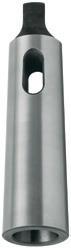
-
-
Drills Jobber, Silver & Blue Bullet
19 0105 1.05 34 12 D101 0105 D102 0105 0107 1.07 58 41 17 D101 0107 • 0109 1.09 57 44 19 D101 0109 • 0110 1.10 36 14 D101 0110 D102 0110 0115 1.15 36 14 D101 0115 D102 0115 0118 1.18 56 44 19 D101 0118 • 0119 1.19 3/64 44 19 D101 0119 D102 0119 0120 1.20 38 16 D101 0120 D102 0120 0125 1.25 38 16 D101 0125 D102 0125 0130 1.30 38 16 D101 0130 D102 0130 0132 1.32 55 48 22 D101 0132 • 0135 1.35 38 16 D101 0135 D102 0135 0139 1.40 54 48 22 D101 0139 • 0140 1.40 40 18 D101 0140 D102 0140 0145 1.45 40 18 D101 0145 D102 0145 0150 1.50 40 18 D101 0150 D102 0150 0151 1.51 53 48 22 D101 0151 • 0155 1.55 40 18 D101 0155 D102 0155 0159 1.59 1/16 43 20 D101 0159 D102 0159 0160 1.60 43 20 D101 0160 D102 0160 0161 1.61 52 48 22 D101 0161 • 0165 1.65 43 20 D101 0165 D102 0165 0170 1.70 43 20 D101 0170 D102 0170 0171 1.70 51 51 25 D101 0171 • 0175 1.75 43 20 D101 0175 D102 0175 0178 1.78 50 51 25 D101 0178 • 0180 1.80 46 22 D101 0180 D102 0180 0185 1.85 46 22 D101 0185 D102 0185 0184 1.85 49 51 25 D101 0184 • 0190 1.90 46 22 D101 0190 D102 0190 0193 1.93 48 51 25 D101 0193 • 0195 1.95 46 22 D101 0195 D102 0195 0198 1.98 5/64 49 24 D101 0198 D102 0198 0199 1.99 47 49 24 D101 0199 • 0200 2.00 49 24 D101 0200 D102 0200 0205 2.05 49 24 D101 0205 D102 0205 0206 2.06 46 54 29 D101 0206 • 0208 2.08 45 54 29 D101 0208 • 0210 2.10 49 24 D101 0210 D102 0210 0215 2.15 49 24 D101 0215 D102 0215 0218 2.18 44 54 29 D101 0218 • 0220 2.20 53 27 D101 0220 D102 0220 P Steel M Stainless Steel K Cast Iron N Non-Ferrous Metals S Titanium & Super Alloys H Hard Materials D102 D101 VDI 3323 ISO • • 1 P • • 2 • • 3 • • 4 • 5 • • 6 • • 7 • 8 • 9 • • 10 • 11 12 • 13 • 14.1 M • 14.2 14.3 • • 15 K • 16 • • 17 • 18 • 19 • 20 • • 21 N • • 22 • 23 • 24 • 25 • 26 • 27 • 28 • • 29 30 31 S 32 33 34 35 36 37.1 37.2 37.3 37.4 37.5 • Optimal • Effective 38.1 H 38.2 39.1 39.2 • • 40 41 - General purpose drill - Designed for machine and hand held drilling Catalogue Code D101 D102 Discount Group A0402 A0402 Material HSS HSS Surface Finish Brt Blu Sutton Designation N N Geometry R30 R30 Point Type 118° Standard 118° Standard Order Quantity Bulk (10) Bulk (10) Size Ref. d1 (h8) l1 l2 Item # Item # mm gauge
• Available on request as special manufacture. Subject to lead time. † Web thinning only applies to metric sizes Contents Index
Drills Jobber, Silver & Blue Bullet
20 0225 2.25 53 27 D101 0225 D102 0225 0226 2.26 43 57 32 D101 0226 • 0230 2.30 53 27 D101 0230 D102 0230 0235 2.35 53 27 D101 0235 D102 0235 0237 2.37 42 57 32 D101 0237 • 0238 2.38 3/32 57 30 D101 0238 D102 0238 0240 2.40 57 30 D101 0240 D102 0240 0244 2.44 41 60 35 D101 0244 • 0245 2.45 57 30 D101 0245 D102 0245 0249 2.49 40 60 35 D101 0249 • 0250 2.50 57 30 D101 0250 D102 0250 0253 2.53 39 60 35 D101 0253 • 0255 2.55 57 30 D101 0255 D102 0255 0258 2.58 38 64 37 D101 0258 • 0260 2.60 57 30 D101 0260 D102 0260 0264 2.64 37 64 37 D101 0264 • 0265 2.65 57 30 D101 0265 D102 0265 0270 2.70 61 33 D101 0270 D102 0270 0271 2.70 36 64 37 D101 0271 • 0275 2.75 61 33 D101 0275 D102 0275 0318 2.78 7/64 61 33 D101 0278 D102 0278 0279 2.79 35 61 33 D101 0279 • 0280 2.80 61 33 D101 0280 D102 0280 0282 2.82 34 67 38 D101 0282 • 0285 2.85 61 33 D101 0285 D102 0285 0287 2.87 33 67 38 D101 0287 • 0290 2.90 61 33 D101 0290 D102 0290 0294 2.95 32 70 41 D101 0294 • 0295 2.95 61 33 D101 0295 D102 0295 0300 3.00 61 33 D101 0300 D102 0300 0305 3.05 31 70 41 D101 0305 • 0310 3.10 65 36 D101 0310 D102 0310 0318 3.18 1/8 65 36 D101 0318 D102 0318 0320 3.20 65 36 D101 0320 D102 0320 0325 3.25 65 36 • • 0326 3.26 30 70 41 D101 0326 • 0330 3.30 65 36 D101 0330 D102 0330 0340 3.40 70 39 D101 0340 D102 0340 0345 3.45 29 73 44 D101 0345 • 0350 3.50 70 39 D101 0350 D102 0350 0356 3.57 28 73 44 D101 0356 • 0357 3.57 9/64 73 44 D101 0357 D102 0357 P Steel M Stainless Steel K Cast Iron N Non-Ferrous Metals S Titanium & Super Alloys H Hard Materials D102 D101 VDI 3323 ISO • • 1 P • • 2 • • 3 • • 4 • 5 • • 6 • • 7 • 8 • 9 • • 10 • 11 12 • 13 • 14.1 M • 14.2 14.3 • • 15 K • 16 • • 17 • 18 • 19 • 20 • • 21 N • • 22 • 23 • 24 • 25 • 26 • 27 • 28 • • 29 30 31 S 32 33 34 35 36 37.1 37.2 37.3 37.4 37.5 • Optimal • Effective 38.1 H 38.2 39.1 39.2 • • 40 41
- General purpose drill - Designed for machine and hand held drilling • Available on request as special manufacture. Subject to lead time. † Web thinning only applies to metric sizes Catalogue Code D101 D102 Discount Group A0402 A0402 Material HSS HSS Surface Finish Brt Blu Sutton Designation N N Geometry R30 R30 Point Type 118° Form A Standard† 118° Form A Standard† Order Quantity Bulk (10) ≥3.5 Bulk (10) ≥3.5 Size Ref. d1 (h8) l1 l2 Item # Item # mm gauge A Contents Index
Drills Jobber, Silver & Blue Bullet
21 0360 3.60 70 39 D101 0360 D102 0360 0366 3.66 27 76 48 D101 0366 • 0370 3.70 70 39 D101 0370 D102 0370 0373 3.73 26 76 48 D101 0373 • 0375 3.75 75 43 • D102 0375 0379 3.80 25 76 48 D101 0379 • 0380 3.80 75 43 D101 0380 D102 0380 0386 3.86 24 79 51 D101 0386 • 0390 3.90 75 43 D101 0390 D102 0390 0391 3.91 23 79 51 D101 0391 • 0397 3.97 5/32 75 43 D101 0397 D102 0397 0399 3.99 22 79 51 D101 0399 • 0400 4.00 75 43 D101 0400 D102 0400 0404 4.04 21 83 54 D101 0404 • 0409 4.09 20 83 54 D101 0409 • 0410 4.10 75 43 D101 0410 D102 0410 0420 4.20 75 43 D101 0420 D102 0420 0422 4.22 19 83 54 D101 0422 • 0425 4.25 80 47 • D102 0425 0430 4.30 80 47 D101 0430 D102 0430 0431 4.30 18 83 54 D101 0431 • 0437 4.37 11/64 80 47 D101 0437 D102 0437 0439 4.39 17 86 56 D101 0439 • 0440 4.40 80 47 D101 0440 D102 0440 0449 4.50 16 86 56 D101 0449 • 0450 4.50 80 47 D101 0450 D102 0450 0457 4.57 15 86 56 D101 0457 • 0460 4.60 80 47 D101 0460 D102 0460 0462 4.62 14 86 56 D101 0462 • 0469 4.70 13 89 59 D101 0469 • 0470 4.70 80 47 D101 0470 D102 0470 0475 4.75 80 47 • D102 0475 0476 4.76 3/16 86 52 D101 0476 D102 0476 0480 4.80 86 52 D101 0480 D102 0480 0481 4.80 12 89 59 D101 0481 • 0485 4.85 11 89 59 D101 0485 • 0490 4.90 86 52 D101 0490 D102 0490 0491 4.91 10 92 62 D101 0491 • 0498 4.98 9 92 62 D101 0498 • 0500 5.00 86 52 D101 0500 D102 0500 0506 5.05 8 92 62 D101 0506 • 0510 5.10 86 52 D101 0510 D102 0510 P Steel M Stainless Steel K Cast Iron N Non-Ferrous Metals S Titanium & Super Alloys H Hard Materials D102 D101 VDI 3323 ISO • • 1 P • • 2 • • 3 • • 4 • 5 • • 6 • • 7 • 8 • 9 • • 10 • 11 12 • 13 • 14.1 M • 14.2 14.3 • • 15 K • 16 • • 17 • 18 • 19 • 20 • • 21 N • • 22 • 23 • 24 • 25 • 26 • 27 • 28 • • 29 30 31 S 32 33 34 35 36 37.1 37.2 37.3 37.4 37.5 • Optimal • Effective 38.1 H 38.2 39.1 39.2 • • 40 41
- General purpose drill - Designed for machine and hand held drilling • Available on request as special manufacture. Subject to lead time. † Web thinning only applies to metric sizes Catalogue Code D101 D102 Discount Group A0402 A0402 Material HSS HSS Surface Finish Brt Blu Sutton Designation N N Geometry R30 R30 Point Type 118° Form A >+ 4mm† 118° Form A >+ 4mm† Order Quantity Bulk (10) Bulk (10) Size Ref. d1 (h8) l1 l2 Item # Item # mm gauge A Contents Index
Drills Jobber, Silver & Blue Bullet
22 0511 5.10 7 92 62 D101 0511 • 0516 5.16 13/64 86 52 D101 0516 D102 0516 0518 5.18 6 95 64 D101 0518 • 0520 5.20 86 52 D101 0520 D102 0520 0522 5.22 5 95 64 D101 0522 • 0525 5.25 86 52 • D102 0525 0530 5.30 86 52 D101 0530 D102 0530 0531 5.31 4 95 64 D101 0531 • 0540 5.40 93 57 D101 0540 D102 0540 0541 5.41 3 95 64 D101 0541 • 0550 5.50 93 57 D101 0550 D102 0550 0556 5.56 7/32 93 57 D101 0556 D102 0556 0560 5.60 93 57 D101 0560 D102 0560 0561 5.61 2 98 67 D101 0561 • 0570 5.70 93 57 D101 0570 D102 0570 0575 5.75 93 57 • D102 0575 0579 5.79 1 98 67 D101 0579 • 0580 5.80 93 57 D101 0580 D102 0580 0590 5.90 93 57 D101 0590 D102 0590 0595 5.95 15/64 93 57 D101 0595 D102 0595 0600 6.00 93 57 D101 0600 D102 0600 0610 6.10 101 63 D101 0610 D102 0610 0620 6.20 101 63 D101 0620 D102 0620 0625 6.25 101 63 • D102 0625 0630 6.30 101 63 D101 0630 D102 0630 0635 6.35 1/4 101 63 D101 0635 D102 0635 0640 6.40 101 63 D101 0640 D102 0640 0650 6.50 101 63 D101 0650 D102 0650 0660 6.60 101 63 D101 0660 D102 0660 0670 6.70 101 63 D101 0670 D102 0670 0675 6.75 109 69 D101 0675 D102 0675 0676 6.75 17/64 105 73 D101 0676 D102 0676 0680 6.80 109 69 D101 0680 D102 0680 0690 6.90 109 69 D101 0690 D102 0690 0700 7.00 109 69 D101 0700 D102 0700 0710 7.10 109 69 D101 0710 D102 0710 0714 7.14 9/32 109 69 j D102 0714 0720 7.20 109 69 D101 0720 D102 0720 0725 7.25 109 69 • D102 0725 0730 7.30 109 69 D101 0730 D102 0730 0740 7.40 109 69 D101 0740 D102 0740 0750 7.50 109 69 D101 0750 D102 0750 P Steel M Stainless Steel K Cast Iron N Non-Ferrous Metals S Titanium & Super Alloys H Hard Materials D102 D101 VDI 3323 ISO • • 1 P • • 2 • • 3 • • 4 • 5 • • 6 • • 7 • 8 • 9 • • 10 • 11 12 • 13 • 14.1 M • 14.2 14.3 • • 15 K • 16 • • 17 • 18 • 19 • 20 • • 21 N • • 22 • 23 • 24 • 25 • 26 • 27 • 28 • • 29 30 31 S 32 33 34 35 36 37.1 37.2 37.3 37.4 37.5 • Optimal • Effective 38.1 H 38.2 39.1 39.2 • • 40 41
- General purpose drill - Designed for machine and hand held drilling • Available on request as special manufacture. Subject to lead time. † Web thinning only applies to metric sizes Catalogue Code D101 D102 Discount Group A0402 A0402 Material HSS HSS Surface Finish Brt Blu Sutton Designation N N Geometry R30 R30 Point Type 118°Form A† 118° Form A† Order Quantity Bulk (10) Bulk (10) Size Ref. d1 (h8) l1 l2 Item # Item # mm gauge D A Contents Index
Drills Jobber, Silver & Blue Bullet
23 0754 7.54 19/64 117 75 D101 0754 D102 0754 0760 7.60 117 75 D101 0760 D102 0760 0770 7.70 117 75 D101 0770 D102 0770 0775 7.75 117 75 • D102 0775 0780 7.80 117 75 D101 0780 D102 0780 0790 7.90 117 75 D101 0790 D102 0790 0794 7.94 5/16 117 75 D101 0794 D102 0794 0800 8.00 117 75 D101 0800 D102 0800 0810 8.10 117 75 D101 0810 D102 0810 0820 8.20 117 75 D101 0820 D102 0820 0825 8.25 117 75 • D102 0825 0830 8.30 117 75 D101 0830 D102 0830 0833 8.33 21/64 117 75 D101 0833 D102 0833 0840 8.40 117 75 D101 0840 D102 0840 0850 8.50 117 75 D101 0850 D102 0850 0860 8.60 125 81 D101 0860 D102 0860 0870 8.70 125 81 D101 0870 D102 0870 0873 8.73 11/32 125 81 D101 0873 D102 0873 0875 8.75 125 81 • D102 0875 0880 8.80 125 81 D101 0880 D102 0880 0890 8.90 125 81 D101 0890 D102 0890 0900 9.00 125 81 D101 0900 D102 0900 0910 9.10 125 81 D101 0910 D102 0910 0913 9.13 23/64 125 81 D101 0913 D102 0913 0920 9.20 125 81 D101 0920 D102 0920 0925 9.25 125 81 • D102 0925 0930 9.30 125 81 D101 0930 D102 0930 0940 9.40 125 81 D101 0940 D102 0940 0950 9.50 125 81 D101 0950 D102 0950 0953 9.52 3/8 133 87 D101 0953 D102 0953 0960 9.60 133 87 D101 0960 D102 0960 0970 9.70 133 87 D101 0970 D102 0970 0975 9.75 133 87 • D102 0975 0980 9.80 133 87 D101 0980 D102 0980 0990 9.90 133 87 D101 0990 D102 0990 0992 9.92 25/64 133 87 D101 0992 D102 0992 1000 10.00 133 87 D101 1000 D102 1000 1010 10.10 133 87 D101 1010 D102 1010 1020 10.20 133 87 D101 1020 D102 1020 1025 10.25 133 87 • D102 1025 1030 10.30 133 87 D101 1030 D102 1030 1032 10.32 13/32 133 87 D101 1032 D102 1032 P Steel M Stainless Steel K Cast Iron N Non-Ferrous Metals S Titanium & Super Alloys H Hard Materials D102 D101 VDI 3323 ISO • • 1 P • • 2 • • 3 • • 4 • 5 • • 6 • • 7 • 8 • 9 • • 10 • 11 12 • 13 • 14.1 M • 14.2 14.3 • • 15 K • 16 • • 17 • 18 • 19 • 20 • • 21 N • • 22 • 23 • 24 • 25 • 26 • 27 • 28 • • 29 30 31 S 32 33 34 35 36 37.1 37.2 37.3 37.4 37.5 • Optimal • Effective 38.1 H 38.2 39.1 39.2 • • 40 41
- General purpose drill - Designed for machine and hand held drilling • Available on request as special manufacture. Subject to lead time. † Web thinning only applies to metric sizes Catalogue Code D101 D102 Discount Group A0402 A0402 Material HSS HSS Surface Finish Brt Blu Sutton Designation N N Geometry R30 R30 Point Type 118° Form A† 118° Form A† Order Quantity Bulk (5) Bulk (5) Size Ref. d1 (h8) l1 l2 Item # Item # mm gauge D A Contents Index
Drills Jobber, Silver & Blue Bullet
24 1040 10.40 133 87 D101 1040 D102 1040 1050 10.50 133 87 D101 1050 D102 1050 1060 10.60 133 87 D101 1060 D102 1060 1070 10.70 142 94 D101 1070 D102 1070 1072 10.72 27/64 142 94 D101 1072 D102 1072 1075 10.75 142 94 • D102 1075 1080 10.80 142 94 D101 1080 D102 1080 1090 10.90 142 94 D101 1090 D102 1090 1100 11.00 142 94 D101 1100 D102 1100 1110 11.10 142 94 D101 1110 D102 1110 1111 11.11 7/16 142 94 D101 1111 D102 1111 1120 11.20 142 94 D101 1120 D102 1120 1125 11.25 142 94 • D102 1125 1130 11.30 142 94 D101 1130 D102 1130 1140 11.40 142 94 D101 1140 D102 1140 1150 11.50 142 94 D101 1150 D102 1150 1151 11.51 29/64 142 94 D101 1151 D102 1151 1160 11.60 142 94 D101 1160 D102 1160 1170 11.70 142 94 D101 1170 D102 1170 1175 11.75 142 94 • D102 1175 1180 11.80 142 94 D101 1180 D102 1180 1190 11.90 142 94 D101 1190 D102 1190 1191 11.91 15/32 151 101 D101 1191 D102 1191 1200 12.00 151 101 D101 1200 D102 1200 1210 12.10 151 101 D101 1210 D102 1210 1220 12.20 151 101 D101 1220 D102 1220 1225 12.25 151 101 • D102 1225 1230 12.30 151 101 D101 1230 D102 1230 1231 12.30 31/64 149 111 D101 1231 D102 1231 1240 12.40 151 101 D101 1240 D102 1240 1250 12.50 151 101 D101 1250 D102 1250 1260 12.60 151 101 D101 1260 D102 1260 1270 12.70 1/2 151 101 D101 1270 D102 1270 1275 12.75 151 101 • D102 1275 1280 12.80 151 101 D101 1280 D102 1280 1290 12.90 151 101 D101 1290 D102 1290 1300 13.00 151 101 D101 1300 D102 1300 1310 13.10 33/64 151 101 • D102 1310 1320 13.20 151 101 • D102 1320 1349 13.49 17/32 160 108 • D102 1349 1350 13.50 160 108 D102 1350 1380 13.80 160 108 • D102 1380 P Steel M Stainless Steel K Cast Iron N Non-Ferrous Metals S Titanium & Super Alloys H Hard Materials D102 D101 VDI 3323 ISO • • 1 P • • 2 • • 3 • • 4 • 5 • • 6 • • 7 • 8 • 9 • • 10 • 11 12 • 13 • 14.1 M • 14.2 14.3 • • 15 K • 16 • • 17 • 18 • 19 • 20 • • 21 N • • 22 • 23 • 24 • 25 • 26 • 27 • 28 • • 29 30 31 S 32 33 34 35 36 37.1 37.2 37.3 37.4 37.5 • Optimal • Effective 38.1 H 38.2 39.1 39.2 • • 40 41
- General purpose drill - Designed for machine and hand held drilling • Available on request as special manufacture. Subject to lead time. † Web thinning only applies to metric sizes Catalogue Code D101 D102 Discount Group A0402 A0402 Material HSS HSS Surface Finish Brt Blu Sutton Designation N N Geometry R30 R30 Point Type 118° Form A† 118° Form A† Order Quantity Bulk (5) Bulk (5) Size Ref. d1 (h8) l1 l2 Item # Item # mm gauge A Contents Index
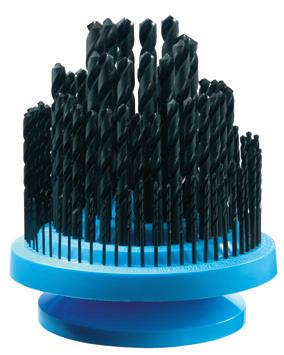
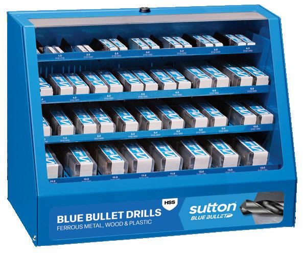
DMB25M Metric Bulk Drill Bits (405 Pieces)
20 each: 1.0, 1.5, 2.0, 2.5, 3.0, 3.5, 4.0, 4.5, 5.0, 5.5, 6.0, 6.5, 8.0mm
10 each: 7.0, 7.5, 8.5, 9.0, 9.5, 10.0, 13.0mm
5 each: 10.5, 11.0, 11.5, 12.0, 12.5mm
DMB29 Imperial Bulk Drill Bits (375 Pieces)
20 each: 1/16, 5/64, 3/32, 7/64, 1/8, 9/64, 5/32, 11/64, 3/16, 1/4, 5/16
10 each: 13/64, 7/32, 15/64, 17/64, 9/32, 19/64, 21/64, 11/32, 23/64, 3/8, 7/16, 1/2
5 each: 25/64, 13/32, 27/64, 29/64, 15/32, 31/64
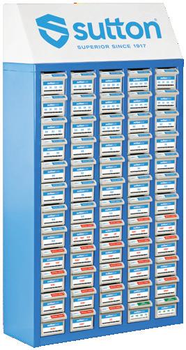
Bulk Counter Stand (No Product)
25 1389 13.89 35/64 160 108 • D102 1389 1400 14.00 160 108 • D102 1400 1425 14.25 169 114 • D102 1425 1429 14.29 9/16 169 114 • D102 1429 1450 14.50 169 114 • D102 1450 1468 14.68 37/64 169 114 • D102 1468 1475 14.75 169 114 • D102 1475 1500 15.00 169 114 • D102 1500 1508 15.08 19/32 178 120 • D102 1508 1525 15.25 178 120 • D102 1525 1548 15.48 39/64 178 120 • D102 1548 1550 15.50 178 120 • D102 1550 1575 15.75 178 120 • D102 1575 1588 15.88 5/8 178 120 • D102 1588 1600 16.00 178 120 • D102 1600 1627 16.27 41/64 184 125 • D102 1627 1667 16.67 21/32 184 125 • D102 1667 1707 17.07 43/64 191 130 • D102 1707 1746 17.46 11/16 191 130 • D102 1746
Merchandisers
MER405
MER405
D101
D102
D101
MER375
4999 99836 4999 99836 60 drawer Parts Cabinet (No Product) 4999 99847 4999 99847 60 drawer Parts Cabinet Label Kit 4999 83002 4999 83000 P Steel M Stainless Steel K Cast Iron N Non-Ferrous Metals S Titanium & Super Alloys H Hard Materials D102 D101 VDI 3323 ISO • • 1 P • • 2 • • 3 • • 4 • 5 • • 6 • • 7 • 8 • 9 • • 10 • 11 12 • 13 • 14.1 M • 14.2 14.3 • • 15 K • 16 • • 17 • 18 • 19 • 20 • • 21 N • • 22 • 23 • 24 • 25 • 26 • 27 • 28 • • 29 30 31 S 32 33 34 35 36 37.1 37.2 37.3 37.4 37.5 • Optimal • Effective 38.1 H 38.2 39.1 39.2 • • 40 41
- General purpose drill - Designed for machine and
held drilling • Available on request as special manufacture. Subject to lead time. † Web thinning only applies to metric sizes Catalogue Code D101 D102 Discount Group A0402 A0402 Material HSS HSS Surface Finish Brt Blu Sutton Designation N N Geometry R30 R30 Point Type 118° Form A† 118° Form A† Order Quantity 1 1 Size Ref. d1 (h8) l1 l2 Item # Item # mm gauge A 4999 99847 4999 99836 Contents Index
D102 MER375
Drills Jobber, Silver & Blue Bullet
hand
- General purpose drill
- Web thinned†
- Split point for
- Designed for machine and hand held drilling
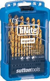
26 0034 0.34 80 19 3 • 0035 0.35 19 4 • 0037 0.37 79 19 3 • 0038 0.38 19 4 • 0040 0.40 20 5 • 0041 0.41 78 22 5 • 0042 0.42 20 5 • 0045 0.45 20 5 • 0046 0.46 77 22 5 • 0048 0.48 20 5 • 0050 0.50 22 6 • 0051 0.51 76 22 5 • 0052 0.52 22 6 • 0053 0.53 75 25 6 • 0055 0.55 24 7 • 0057 0.57 74 25 6 • 0060 0.60 24 7 • 0061 0.61 73 29 8 • 0063 0.63 72 29 8 • 0065 0.65 26 8 • 0066 0.66 71 32 10 • 0070 0.70 28 9 • 0071 0.71 70 32 10 • 0074 0.74 69 35 13 • 0075 0.75 28 9 • 0078 0.79 68 35 13 • 0080 0.80 30 10 • 0081 0.81 67 35 13 • 0084 0.84 66 35 13 • 0085 0.85 30 10 • 0089 0.89 65 38 16 • 0090 0.90 32 11 • 0091 0.91 64 38 16 • 0094 0.94 63 38 16 • 0095 0.95 32 11 • 0096 0.96 62 38 16 • 0099 0.99 61 41 17 • 0100 1.00 34 12 D103 0100 D179 0100 0102 1.02 60 41 17 • 0104 1.04 59 41 17 • 0105 1.05 34 12 D103 0105 0110 1.10 36 14 D103 0110 D179 0110 P Steel M Stainless Steel K Cast Iron N Non-Ferrous Metals S Titanium & Super Alloys H Hard Materials D179 D103 VDI 3323 ISO • • 1 P • • 2 • • 3 • • 4 • • 5 • • 6 • • 7 • • 8 • • 9 • • 10 • • 11 • • 12 • • 13 • • 14.1 M • • 14.2 • 14.3 • • 15 K • • 16 • • 17 • • 18 • • 19 • • 20 21 N 22 • • 23 • • 24 • • 25 • • 26 • • 27 • • 28 • • 29 30 31 S 32 33 34 35 36 37.1 37.2 37.3 37.4 37.5 • Optimal • Effective 38.1 H 38.2 39.1 39.2 • • 40 41 Catalogue Code D103 D179 Discount Group A0420 A0402 Material HSS HSS Surface Finish TiN TiAIN Tip Sutton Designation N N Geometry R30 R30 Point Type 118° Form A 118° Form C Order Quantity 1 Bulk (10) Size Ref. d1 (h8) l1 l2 Item # Item # mm gauge
easier
point for
penetration
easier
penetration
• Available on request as special manufacture. Subject to lead time. † Web thinning only applies to metric sizes
TiNite, Viper Plus 26 26 D Contents Index
Drills Jobber,
Drills Jobber, TiNite,
27 0115 1.15 36 14 D103 0115 0119 1.19 3/64 44 19 D179 0119 0120 1.20 38 16 D103 0120 D179 0120 0125 1.25 38 16 D103 0125 0130 1.30 38 16 D103 0130 D179 0130 0135 1.35 38 16 D103 0135 0140 1.40 40 18 D103 0140 D179 0140 0145 1.45 40 18 D103 0145 0150 1.50 40 18 D103 0150 D179 0150 0155 1.55 40 18 D103 0155 0159 1.59 1/16 43 20 D179 0159 0160 1.60 43 20 D103 0160 D179 0160 0165 1.65 43 20 D103 0165 0170 1.70 43 20 D103 0170 D179 0170 0175 1.75 43 20 D103 0175 0180 1.80 46 22 D103 0180 D179 0180 0185 1.85 46 22 D103 0185 0190 1.90 46 22 D103 0190 D179 0190 0195 1.95 46 22 D103 0195 0198 1.98 5/64 49 24 D179 0198 0200 2.00 49 24 D103 0200 D179 0200 0205 2.05 49 24 D103 0205 0210 2.10 49 24 D103 0210 D179 0210 0215 2.15 49 24 D103 0215 0220 2.20 53 27 D103 0220 D179 0220 0225 2.25 53 27 D103 0225 0230 2.30 53 27 D103 0230 D179 0230 0235 2.35 53 27 D103 0235 0238 2.38 3/32 57 30 D179 0238 0240 2.40 57 30 D103 0240 D179 0240 0245 2.45 57 30 D103 0245 0250 2.50 57 30 D103 0250 D179 0250 0255 2.55 57 30 D103 0255 0260 2.60 57 30 D103 0260 D179 0260 0265 2.60 57 30 D103 0265 0270 2.70 61 33 D103 0270 D179 0270 0275 2.75 61 33 D103 0275 0278 2.78 7/64 61 33 D179 0278 0280 2.80 61 33 D103 0280 D179 0280 0285 2.85 61 33 D103 0285 0290 2.90 61 33 D103 0290 D179 0290 0300 3.00 61 33 D103 0300 D179 0300 P Steel M Stainless Steel K Cast Iron N Non-Ferrous Metals S Titanium & Super Alloys H Hard Materials D179 D103 VDI 3323 ISO • • 1 P • • 2 • • 3 • • 4 • • 5 • • 6 • • 7 • • 8 • • 9 • • 10 • • 11 • • 12 • • 13 • • 14.1 M • • 14.2 • 14.3 • • 15 K • • 16 • • 17 • • 18 • • 19 • • 20 21 N 22 • • 23 • • 24 • • 25 • • 26 • • 27 • • 28 • • 29 30 31 S 32 33 34 35 36 37.1 37.2 37.3 37.4 37.5 • Optimal • Effective 38.1 H 38.2 39.1 39.2 • • 40 41 - General purpose drill
Web thinned† point for easier penetration
Split point for easier penetration
Designed for machine and hand held drilling • Available on request as special manufacture. Subject to lead time. Catalogue Code D103 D179 Discount Group A0420 A0402 Material HSS HSS Surface Finish TiN TiAIN Tip Sutton Designation N N Geometry R30 R30 Point Type 118° Form A 118° Form C Order Quantity 1 Bulk (10) Size Ref. d1 (h8) l1 l2 Item # Item # mm gauge
-
-
-
Viper
C D Contents Index
Plus
Drills Jobber, TiNite,
28 0310 3.10 65 36 D103 0310 D179 0310 0318 3.18 1/8 65 36 D179 0318 0320 3.20 65 36 D103 0320 D179 0320 0330 3.30 65 36 D103 0330 D179 0330 0340 3.40 70 39 D103 0340 D179 0340 0350 3.50 70 39 D103 0350 D179 0350 0357 3.57 9/64 70 39 D179 0357 0360 3.60 70 39 D103 0360 D179 0360 0370 3.70 70 39 D103 0370 D179 0370 0380 3.80 75 43 D103 0380 D179 0380 0390 3.90 75 43 D103 0390 D179 0390 0397 3.97 5/32 75 43 D179 0397 0400 4.00 75 43 D103 0400 D179 0400 0410 4.10 75 43 D103 0410 D179 0410 0420 4.20 75 43 D103 0420 D179 0420 0430 4.30 80 47 D103 0430 D179 0430 0437 4.37 11/64 80 47 D179 0437 0440 4.40 80 47 D103 0440 D179 0440 0450 4.50 80 47 D103 0450 D179 0450 0460 4.60 80 47 D103 0460 D179 0460 0470 4.70 80 47 D103 0470 D179 0470 0476 4.76 3/16 86 52 D179 0476 0480 4.80 86 52 D103 0480 D179 0480 0490 4.90 86 52 D103 0490 D179 0490 0500 5.00 86 52 D103 0500 D179 0500 0510 5.10 86 52 D103 0510 D179 0510 0516 5.16 13/64 86 52 D179 0516 0520 5.20 86 52 D103 0520 D179 0520 0530 5.30 86 52 D103 0530 D179 0530 0540 5.40 93 57 D103 0540 D179 0540 0550 5.50 93 57 D103 0550 D179 0550 0556 5.56 7/32 93 57 D179 0556 0560 5.60 93 57 D103 0560 D179 0560 0570 5.70 93 57 D103 0570 D179 0570 0580 5.80 93 57 D103 0580 D179 0580 0590 5.90 93 57 D103 0590 D179 0590 0595 5.95 15/64 93 57 D179 0595 0600 6.00 93 57 D103 0600 D179 0600 0610 6.10 101 63 D103 0610 D179 0610 0620 6.20 101 63 D103 0620 D179 0620 0630 6.30 101 63 D103 0630 D179 0630 0635 6.35 1/4 101 63 D179 0635 P Steel M Stainless Steel K Cast Iron N Non-Ferrous Metals S Titanium & Super Alloys H Hard Materials D179 D103 VDI 3323 ISO • • 1 P • • 2 • • 3 • • 4 • • 5 • • 6 • • 7 • • 8 • • 9 • • 10 • • 11 • • 12 • • 13 • • 14.1 M • • 14.2 • 14.3 • • 15 K • • 16 • • 17 • • 18 • • 19 • • 20 21 N 22 • • 23 • • 24 • • 25 • • 26 • • 27 • • 28 • • 29 30 31 S 32 33 34 35 36 37.1 37.2 37.3 37.4 37.5 • Optimal • Effective 38.1 H 38.2 39.1 39.2 • • 40 41
General purpose drill
Web thinned† point for easier penetration
Split point for easier penetration
Designed for machine and hand held drilling • Available on request as special manufacture. Subject to lead time. † Web thinning only applies to metric sizes
-
-
-
-
Viper
Catalogue Code D103 D179 Discount Group A0420 A0402 Material HSS HSS Surface Finish TiN TiAIN Tip Sutton Designation N N Geometry R30 R30 Point Type 118° Form A† ≥ 3.5 118° Form C ≥ 3.5 Order Quantity 1 Bulk 10 (5 > 7.5mm) ≥ 5/32" Size Ref. d1 (h8) l1 l2 Item # Item # mm gauge C A D Contents Index
Plus
- Designed for machine and hand held drilling
29 0640 6.40 101 63 D103 0640 D179 0640 0650 6.50 101 63 D103 0650 D179 0650 0660 6.60 101 63 D103 0660 D179 0660 0670 6.70 101 63 D103 0670 D179 0670 0676 6.75 17/64 109 69 D179 0676 0680 6.80 109 69 D103 0680 D179 0680 0690 6.90 109 69 D103 0690 D179 0690 0700 7.00 109 69 D103 0700 D179 0700 0710 7.10 109 69 D103 0710 D179 0710 0714 7.14 9/32 109 69 D179 0714 0720 7.20 109 69 D103 0720 D179 0720 0730 7.30 109 69 D103 0730 D179 0730 0740 7.40 109 69 D103 0740 D179 0740 0750 7.50 109 69 D103 0750 D179 0750 0754 7.54 19/64 117 75 D179 0754 0760 7.60 117 75 D103 0760 D179 0760 0770 7.70 117 75 D103 0770 D179 0770 0780 7.80 117 75 D103 0780 D179 0780 0790 7.90 117 75 D103 0790 D179 0790 0794 7.94 5/16 117 75 D179 0794 0800 8.00 117 75 D103 0800 D179 0800 0810 8.10 117 75 D103 0810 D179 0810 0820 8.20 117 75 D103 0820 D179 0820 0830 8.30 117 75 D103 0830 D179 0830 0833 8.33 21/64 117 75 D179 0833 0840 8.40 117 75 D103 0840 D179 0840 0850 8.50 117 75 D103 0850 D179 0850 0860 8.60 125 81 D103 0860 D179 0860 0870 8.70 125 81 D103 0870 D179 0870 0873 8.73 11/32 125 81 D179 0873 0880 8.80 125 81 D103 0880 D179 0880 0890 8.90 125 81 D103 0890 D179 0890 0900 9.00 125 81 D103 0900 D179 0900 0910 9.10 125 81 D103 0910 D179 0910 0913 9.13 23/64 125 81 D179 0913 0920 9.20 125 81 D103 0920 D179 0920 0930 9.30 125 81 D103 0930 D179 0930 0940 9.40 125 81 D103 0940 D179 0940 0950 9.50 125 81 D103 0950 D179 0950 0953 9.52 3/8 133 87 D179 0953 0960 9.60 133 87 D103 0960 D179 0960 0970 9.70 133 87 D103 0970 D179 0970 0980 9.80 133 87 D103 0980 D179 0980 0990 9.90 133 87 D103 0990 D179 0990 0992 9.92 25/64 133 87 D179 0992 1000 10.00 133 87 D103 1000 D179 1000 1010 10.10 133 87 D103 1010 D179 1010 1020 10.20 133 87 D103 1020 D179 1020 P Steel M Stainless Steel K Cast Iron N Non-Ferrous Metals S Titanium & Super Alloys H Hard Materials D179 D103 VDI 3323 ISO • • 1 P • • 2 • • 3 • • 4 • • 5 • • 6 • • 7 • • 8 • • 9 • • 10 • • 11 • • 12 • • 13 • • 14.1 M • • 14.2 • 14.3 • • 15 K • • 16 • • 17 • • 18 • • 19 • • 20 21 N 22 • • 23 • • 24 • • 25 • • 26 • • 27 • • 28 • • 29 30 31 S 32 33 34 35 36 37.1 37.2 37.3 37.4 37.5 • Optimal • Effective 38.1 H 38.2 39.1 39.2 • • 40 41
- General purpose drill
- Web thinned† point for easier penetration
- Split point for easier penetration
• Available on request as special manufacture. Subject to lead time. † Web thinning only applies to metric sizes
Jobber, TiNite, Viper Plus Catalogue Code D103 D179 Discount Group A0420 A0402 Material HSS HSS Surface Finish TiN TiAIN Tip Sutton Designation N N Geometry R30 R30 Point Type 118° Form A† 118° Form C Order Quantity 1 Bulk 10 (5 > 7.5mm) Size Ref. d1 (h8) l1 l2 Item # Item # mm gauge C A D Contents Index
Drills
Drills Jobber, TiNite,
- General purpose drill
- Web thinned† point for easier
- Split point for easier penetration
- Designed for machine and hand held drilling
30 P Steel M Stainless Steel K Cast Iron N Non-Ferrous Metals S Titanium & Super Alloys H Hard Materials D179 D103 VDI 3323 ISO • • 1 P • • 2 • • 3 • • 4 • • 5 • • 6 • • 7 • • 8 • • 9 • • 10 • • 11 • • 12 • • 13 • • 14.1 M • • 14.2 • 14.3 • • 15 K • • 16 • • 17 • • 18 • • 19 • • 20 21 N 22 • • 23 • • 24 • • 25 • • 26 • • 27 • • 28 • • 29 30 31 S 32 33 34 35 36 37.1 37.2 37.3 37.4 37.5 • Optimal • Effective 38.1 H 38.2 39.1 39.2 • • 40 41 1030 10.30 133 87 D103 1030 D179 1030 1032 10.32 13/32 133 87 D179 1032 1040 10.40 133 87 D103 1040 D179 1040 1050 10.50 133 87 D103 1050 D179 1050 1060 10.60 133 87 D103 1060 D179 1060 1070 10.70 142 94 D103 1070 D179 1070 1072 10.72 27/64 142 94 D179 1072 1080 10.80 142 94 D103 1080 D179 1080 1090 10.90 142 94 D103 1090 D179 1090 1100 11.00 142 94 D103 1100 D179 1100 1110 11.10 142 94 D103 1110 D179 1110 1111 11.11 7/16 142 94 D179 1111 1120 11.20 142 94 D103 1120 D179 1120 1130 11.30 142 94 D103 1130 D179 1130 1140 11.40 142 94 D103 1140 D179 1140 1150 11.50 142 94 D103 1150 D179 1150 1151 11.51 29/64 142 94 D179 1151 1160 11.60 142 94 D103 1160 D179 1160 1170 11.70 142 94 D103 1170 D179 1170 1180 11.80 142 94 D103 1180 D179 1180 1190 11.90 142 94 D103 1190 D179 1190 1191 11.91 15/32 151 101 D179 1191 1200 12.00 151 101 D103 1200 D179 1200 1210 12.10 151 101 D103 1210 D179 1210 1220 12.20 151 101 D103 1220 D179 1220 1230 12.30 151 101 D103 1230 D179 1230 1231 12.30 31/64 151 101 D179 1231 1240 12.40 151 101 D103 1240 D179 1240 1250 12.50 151 101 D103 1250 D179 1250 1260 12.60 151 101 D103 1260 D179 1260 1270 12.70 1/2 151 101 D179 1270 1280 12.80 151 101 D103 1280 D179 1280 1290 12.90 151 101 D103 1290 D179 1290 1300 13.00 151 101 D103 1300 D179 1300 1310 13.10 33/64 151 101 D179 1310 1349 13.49 17/32 160 108 D179 1349 1350 13.50 160 108 D179 1350 1400 14.00 160 108 D179 1400 1429 14.29 9/16 169 114 D179 1429 1450 14.50 169 114 D179 1450 1500 15.00 169 114 D179 1500 1550 15.50 178 120 D179 1550 1588 15.88 5/8 178 120 D179 1588 1600 16.00 178 120 D179 1600
penetration
• Available on request as special manufacture. Subject to lead time. † Web thinning only applies to metric sizes
Viper
Catalogue Code D103 D179 Discount Group A0420 A0402 Material HSS HSS Surface Finish TiN TiAIN Tip Sutton Designation N N Geometry R30 R30 Point Type 118° Form A† 118° Form C Order Quantity 1 Bulk 5 (1 > 13mm) Size Ref. d1 (h8) l1 l2 Item # Item # mm gauge C A Contents Index
Plus
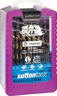
Drills Jobber, Heavy Duty
0100 1.00* 34 12 D109 0100 0110 1.10* 36 14 D109 0110
0120 1.20* 38 16 D109 0120
0130 1.30* 38 16 D109 0130
0140 1.40* 40 18 D109 0140
0150 1.50* 40 18 D109 0150
0159 1.59* 1/16 43 20 D109 0159
0160 1.60* 43 20 D109 0160
0170 1.70* 43 20 D109 0170
0180 1.80* 46 22 D109 0180
0190 1.90* 46 22 D109 0190
0198 1.98* 5/64 49 24 D109 0198
0200 2.00* 49 24 D109 0200
0205 2.05* 49 24 D109 0205
0210 2.10* 49 24 D109 0210
0220 2.20* 53 27 D109 0220
0230 2.30* 53 27 D109 0230
0238 2.38* 3/32 57 30 D109 0238
0240 2.40* 57 30 D109 0240
0250 2.50 57 30 D109 0250
0260 2.60 57 30 D109 0260
0270 2.70 61 33 D109 0270
0278 2.78 7/64 61 33 D109 0278
0280 2.80 61 33 D109 0280
0290 2.90 61 33 D109 0290
0300 3.00 61 33 D109 0300 0310 3.10 65 36 D109 0310
0318 3.18 1/8 65 36 D109 0318 0320 3.20 65 36 D109 0320 0330 3.30 65 36 D109 0330 0340 3.40 70 39 D109 0340 0350 3.50 70 39 D109 0350 0357 3.57 9/64 70 39 D109 0357 0360 3.60 70 39 D109 0360
3.70 70 39 D109 0370
3.80 75 43 D109 0380
3.90 75 43 D109 0390
3.97 5/32 75 43 D109 0397
4.00 75 43 D109 0400
31
0370
0380
0390
0397
0400
D109
0420 4.20 75 43 D109 0420 0430 4.30 80 47 D109 0430 0437 4.37 11/64 80 47 D109 0437 0440 4.40 80 47 D109 0440 0450 4.50 80 47 D109 0450 0460 4.60 80 47 D109 0460 0470 4.70 80 47 D109 0470 0476 4.76 3/16 86 52 D109 0476 0480 4.80 86 52 D109 0480 0490 4.90 86 52 D109 0490 0500 5.00 86 52 D109 0500 0510 5.10 86 52 D109 0510 0516 5.16 13/64 86 52 D109 0516 0520 5.20 86 52 D109 0520 0530 5.30 86 52 D109 0530 0540 5.40 93 57 D109 0540 0550 5.50 93 57 D109 0550 0556 5.56 7/32 93 57 D109 0556 0560 5.60 93 57 D109 0560 0570 5.70 93 57 D109 0570 0580 5.80 93 57 D109 0580 0590 5.90 93 57 D109 0590 0595 5.95 15/64 93 57 D109 0595 0600 6.00 93 57 D109 0600 0610 6.10 101 63 D109 0610 0620 6.20 101 63 D109 0620 0630 6.30 101 63 D109 0630 0635 6.35 1/4 101 63 D109 0635 0640 6.40 101 63 D109 0640 0650 6.50 101 63 D109 0650 0660 6.60 101 63 D109 0660 0670 6.70 101 63 D109 0670 0676 6.75 17/64 109 69 D109 0676 0680 6.80 109 69 D109 0680 0690 6.90 109 69 D109 0690 0700 7.00 109 69 D109 0700 0710 7.10 109 69 D109 0710 0714 7.14 9/32 109 69 D109 0714 0720 7.20 109 69 D109 0720 0730 7.30 109 69 D109 0730 P Steel M Stainless Steel K Cast Iron N Non-Ferrous Metals S Titanium & Super Alloys H Hard Materials D109 VDI 3323 ISO 1 P 2 • 3 • 4 • 5 6 • 7 • 8 • 9 • 10 • 11 12 13 • 14.1 M • 14.2 14.3 • 15 K • 16 • 17 • 18 • 19 • 20 21 N 22 23 24 25 26 • 27 28 29 30 31 S 32 33 34 35 36 37.1 37.2 37.3 37.4 37.5 • Optimal • Effective • 38.1 H 38.2 39.1 39.2 • 40 41
0410 4.10 75 43
0410
- Heavy duty design
Cobalt content ensures high abrasion resistance
Suitable for hard materials up to 850N/mm2 - Self centring 135° split point * Standard 135° point below 3/00" Catalogue Code D109 Discount Group A0404 Material HSS Co Surface Finish Colour Temp Sutton Designation Hard Materials Geometry R25 Point Type 135° Form C > 3/32* ≥ 3.0 ≥ 1/8" Order Quantity Bulk (10) Size Ref. d1 (h8) l1 l2 Item # Size Ref. d1 (h8) l1 l2 Item # mm inch mm inch 31 Contents Index
-
-
Drills Jobber, Heavy Duty
0740 7.40 109 69 D109 0740
0750 7.50 109 69 D109 0750
0754 7.54 19/64 117 75 D109 0754
0760 7.60 117 75 D109 0760
0770 7.70 117 75 D109 0770
0780 7.80 117 75 D109 0780
0790 7.90 117 75 D109 0790
0794 7.94 5/16 117 75 D109 0794
0800 8.00 117 75 D109 0800
0810 8.10 117 75 D109 0810
0820 8.20 117 75 D109 0820
0830 8.30 117 75 D109 0830
0833 8.33 21/64 117 75 D109 0833
0840 8.40 117 75 D109 0840
0850 8.50 117 75 D109 0850
0860 8.60 125 81 D109 0860
0870 8.70 125 81 D109 0870
0873 8.73 11/32 125 81 D109 0873
0880 8.80 125 81 D109 0880
0890 8.90 125 81 D109 0890
0900 9.00 125 81 D109 0900
0910 9.10 125 81 D109 0910
0913 9.13 23/64 125 81 D109 0913
0920 9.20 125 81 D109 0920
0930 9.30 125 81 D109 0930
0940 9.40 125 81 D109 0940
0950 9.50 125 81 D109 0950
0953 9.52 3/8 133 87 D109 0953
0960 9.60 133 87 D109 0960
0970 9.70 133 87 D109 0970
0980 9.80 133 87 D109 0980
0990 9.90 133 87 D109 0990
0992 9.92 25/64 133 87 D109 0992
10.00 133 87 D109 1000 1010 10.10 133 87 D109 1010
1020 10.20 133 87 D109 1020 1030 10.30 133 87 D109 1030 1032 10.32 13/32 133 87 D109 1032 1040 10.40 133 87 D109 1040
10.50 133 87 D109 1050
32
1000
1060 10.60 133 87 D109 1060 1070 10.70 142 94 D109 1070 1072 10.72 27/64 142 94 D109 1072 1080 10.80 142 94 D109 1080 1090 10.90 142 94 D109 1090 1100 11.00 142 94 D109 1100 1111 11.11 7/16 142 94 D109 1111 1110 11.10 142 94 D109 1110 1120 11.20 142 94 D109 1120 1130 11.30 142 94 D109 1130 1140 11.40 142 94 D109 1140 1150 11.50 142 94 D109 1150 1151 11.51 29/64 142 94 D109 1151 1160 11.60 142 94 D109 1160 1170 11.70 142 94 D109 1170 1180 11.80 142 94 D109 1180 1190 11.90 142 94 D109 1190 1191 11.91 15/32 151 101 D109 1191 1200 12.00 151 101 D109 1200 1210 12.10 151 101 D109 1210 1220 12.20 151 101 D109 1220 1230 12.30 151 101 D109 1230 1231 12.30 31/64 149 111 D109 1231 1240 12.40 151 101 D109 1240 1250 12.50 151 101 D109 1250 1260 12.60 151 101 D109 1260 1270 12.70 1/2 151 101 D109 1270 1280 12.80 151 101 D109 1280 1290 12.90 151 101 D109 1290 1300 13.00 151 101 D109 1300 P Steel M Stainless Steel K Cast Iron N Non-Ferrous Metals S Titanium & Super Alloys H Hard Materials D109 VDI 3323 ISO 1 P 2 • 3 • 4 • 5 6 • 7 • 8 • 9 • 10 • 11 12 13 • 14.1 M • 14.2 14.3 • 15 K • 16 • 17 • 18 • 19 • 20 21 N 22 23 24 25 26 • 27 28 29 30 31 S 32 33 34 35 36 37.1 37.2 37.3 37.4 37.5 • Optimal • Effective • 38.1 H 38.2 39.1 39.2 • 40 41
1050
Heavy duty design
content ensures high abrasion resistance
for hard materials up to 850N/mm2
Self centring 135° split point Catalogue Code D109 Discount Group A0404 Material HSS Co Surface Finish Colour Temp Sutton Designation Hard Materials Geometry R25 Point Type 135° Form C > 3/32* Order Quantity Bulk 10 (5 > 7.5mm) Size Ref. d1 (h8) l1 l2 Item # Size Ref. d1 (h8) l1 l2 Item # mm inch mm inch * Standard 135° point below 3/32" Contents Index
-
- Cobalt
- Suitable
-
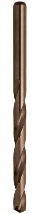
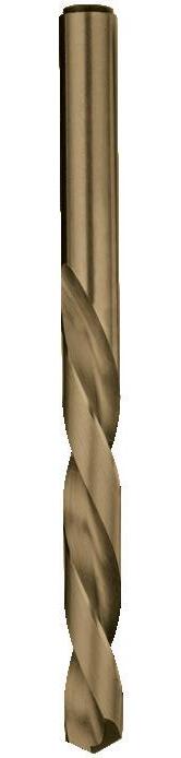
Drills Left Hand Cobalt
- Left hand helix for screw machine applications where spindles rotate counter-clockwise
- Cobalt content ensures high abrasion & heat resistance
- Shorter drilling length designed for rigidity
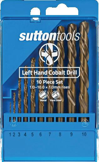
33 0100 1.0 34 12 D202 0100 0200 2.0 49 24 D202 0200 0300 3.0 61 33 D202 0300 0400 4.0 75 43 D202 0400 0500 5.0 86 52 D202 0500 0550 5.5 93 57 D202 0550 0600 6.0 93 57 D202 0600 0700 7.0 109 69 D202 0700 0750 7.5 109 69 D202 0750 0800 8.0 117 75 D202 0800 0900 9.0 125 81 D202 0900 1000 10.0 133 87 D202 1000 1100 11.0 142 94 D202 1100 1200 12.0 151 101 D202 1200 1300 13.0 151 101 D202 1300 Set LH10M 1.0 - 10mm x 1.0mm rises 10
LH10M P Steel M Stainless Steel K Cast Iron N Non-Ferrous Metals S Titanium & Super Alloys H Hard Materials D202 VDI 3323 ISO • 1 P • 2 • 3 • 4 5 • 6 • 7 8 9 • 10 11 12 13 14.1 M 14.2 14.3 • 15 K 16 • 17 18 19 20 • 21 N • 22 • 23 • 24 • 25 • 26 • 27 • 28 • 29 30 31 S 32 33 34 35 36 37.1 37.2 37.3 37.4 37.5 • Optimal • Effective 38.1 H 38.2 39.1 39.2 • 40 41
D202
LH10M
D202
Catalogue Code D202 Discount Group
Material
Co
Finish Colour Temp Sutton Designation
Geometry
Point Type
Standard
Size Ref. d1 l1 l2 Pieces Item #
A0404
HSS
Surface
N
L30
118°
Packaging Telepack
33 Contents Index
Drills Jobber, R40, INOX
- Short flute length jobber drill
- Cost effective solution for austenitic stainless steels and soft materials
- Unique stepped core for excellent penetration
- TiAlN tip for good wear resistance
0100 1.0 34 8 D180 0100
0150 1.5 40 11 D180 0150
0200 2.0 49 14 D180 0200
0250 2.5 57 16 D180 0250
0300 3.0 61 18 D180 0300
0310 3.1 65 20 D180 0310
0318 3.18 1/8 65 20 •
0320 3.2 65 20 D180 0320
0325 3.25 65 20 D180 0325
0330 3.3 65 20 D180 0330
0340 3.4 70 22 D180 0340
0350 3.5 70 22 D180 0350
0357 3.57 9/64 70 22 •
0360 3.6 70 22 D180 0360
0370 3.7 70 22 D180 0370
0375 3.75 75 25 D180 0375
0380 3.8 75 25 D180 0380
0390 3.9 75 25 D180 0390
0397 3.97 5/32 75 25 •
0400 4.0 75 25 D180 0400
0410 4.1 75 25 D180 0410
0420 4.2 75 25 D180 0420
0425 4.25 80 28 D180 0425
0430 4.3 80 28 D180 0430
0437 4.37 11/64 80 28 •
0440 4.4 80 28 D180 0440
0450 4.5 80 28 D180 0450
0460 4.6 80 28 D180 0460
0470 4.7 80 28 D180 0470
0475 4.75 80 28 D180 0475
0476 4.76 3/16 86 32 • 0480 4.8 86 32 D180 0480
0490 4.9 86 32 D180 0490
0500 5.0 86 32 D180 0500
0510 5.1 86 32 D180 0510
0516 5.16 13/64 86 32 • 0520 5.2 86 32 D180 0520
0525 5.25 86 32 D180 0525
0530 5.3 86 32 D180 0530
0540 5.4 93 36 D180 0540
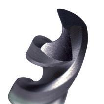
34
0550 5.5 93 36 D180 0550 0556 5.56 7/32 93 36
0560 5.6 93 36 D180
0570 5.7 93 36 D180 0570 0575 5.75 93 36 D180 0575 0580 5.8 93 36 D180 0580 0590 5.9 93 36 D180 0590 0595 5.95 15/64 93 36 • 0600 6.0 93 36 D180 0600 0610 6.1 101 40 D180 0610 0620 6.2 101 40 D180 0620 0625 6.25 101 40 D180 0625 0630 6.3 101 40 D180 0630 0635 6.35 1/4 101 40 • 0640 6.4 101 40 D180 0640 0650 6.5 101 40 D180 0650 0660 6.6 101 40 D180 0660 0670 6.7 101 40 D180 0670 0675 6.75 17/64 101 40 D180 0675 0680 6.8 109 45 D180 0680 0690 6.9 109 45 D180 0690 0700 7.0 109 45 D180 0700 0710 7.1 109 45 D180 0710 0714 7.14 9/32 109 45 • 0720 7.2 109 45 D180 0720 0725 7.25 109 45 D180 0725 0730 7.3 109 45 D180 0730 0740 7.4 109 45 D180 0740 0750 7.5 109 45 D180 0750 0754 7.54 19/64 117 51 • 0760 7.6 117 51 D180 0760 0770 7.7 117 51 D180 0770 0775 7.75 117 51 D180 0775 0780 7.8 117 51 D180 0780 0790 7.9 117 51 D180 0790 0794 7.94 5/16 117 51 • 0800 8.0 117 51 D180 0800 0810 8.1 117 51 D180 0810 0820 8.2 117 51 D180 0820 0825 8.25 117 51 D180 0825
•
0560
Catalogue Code D180 Discount Group A0402 Material HSS Surface Finish TiAlN Tip Sutton Designation VA Geometry R40 Point Type 130° Order Quantity Bulk 10 (5 > 7.5mm) Size Ref. d1 (h8) l1 l2 Item # Size Ref. d1 (h8) l1 l2 Item # mm inch mm inch
• Available on request as special manufacture. Subject to lead time. P Steel M Stainless Steel K Cast Iron N Non-Ferrous Metals S Titanium & Super Alloys H Hard Materials D180 VDI 3323 ISO • 1 P • 2 • 3 • 4 5 • 6 • 7 8 9 10 11 • 12 • 13 • 14.1 M • 14.2 • 14.3 15 K 16 17 18 19 20 • 21 N • 22 • 23 • 24 25 • 26 27 • 28 • 29 30 31 S 32 33 34 35 36 37.1 37.2 37.3 37.4 37.5 • Optimal • Effective 38.1 H 38.2 39.1 39.2 40 41 watch the video 34 Contents Index
Drills Jobber, R40, INOX
- Short flute length jobber drill
- Cost effective solution for austenitic stainless steels and soft materials
- Unique stepped core for excellent penetration
- TiAlN tip for good wear resistance
0830 8.3 117 51 D180 0830 0833 8.33 21/64 117 51 • 0840 8.4 117 51 D180 0840 0850 8.5 117 51 D180 0850 0860 8.6 125 51 D180 0860 0870 8.7 125 57 D180 0870 0873 8.73 11/32 125 57 • 0875 8.75 125 57 D180 0875 0880 8.8 125 57 D180 0880 0890 8.9 125 57 D180 0890 0900 9.0 125 57 D180 0900 0910 9.1 125 57 D180 0910 0913 9.13 23/64 125 57 • 0920 9.2 125 57 D180 0920 0925 9.25 125 57 D180 0925 0930 9.3 125 57 D180 0930 0940 9.4 125 57 D180 0940 0950 9.5 125 57 D180 0950 0953 9.53 3/8 133 63 • 0960 9.6 133 63 D180 0960 0970 9.7 133 63 D180 0970 0975 9.75 133 63 D180 0975 0980 9.8 133 63 D180 0980 0990 9.9 133 63 D180 0990 0992 9.92 25/64 133 63 •
10.0 133 63 D180 1000
35
10.1 133 63 D180 1010 1020 10.2 133 63 D180 1020 1025 10.25 133 63 D180 1025 1030 10.3 133 63 D180 1030 1032 10.32
133 63 • 1040 10.4 133
D180 1040 1050 10.5 133 63 D180 1050 1060 10.6 133 63 D180 1060 1070 10.7 142 71 D180 1070 1072 10.72 27/64 142 71 • 1075 10.75 142 71 D180 1075 1080 10.8 142 71 D180 1080 1090 10.9 142 71 D180 1090 1100 11.0 142 71 D180 1100 1110 11.1 142 71 D180 1110 1111 11.11 7/16 142 71 • 1120 11.2 142 71 D180 1120 1125 11.25 142 71 D180 1125 1130 11.3 142 71 D180 1130 1140 11.4 142 71 D180 1140 1150 11.5 142 71 D180 1150 1151 11.51 29/64 142 71 • 1160 11.6 142 71 D180 1160 1170 11.7 142 71 D180 1170 1175 11.75 142 71 D180 1175 1180 11.8 142 71 D180 1180 1190 11.9 142 78 D180 1190 1191 11.91 15/32 151 78 • 1200 12.0 151 78 D180 1200 1210 12.1 151 78 D180 1210 1220 12.2 151 78 D180 1220 1225 12.25 151 78 D180 1225 1230 12.3 151 78 D180 1230 1230 12.3 31/64 151 78 • 1240 12.4 151 78 D180 1240 1250 12.5 151 78 D180 1250 1260 12.6 151 78 D180 1260 1270 12.7 151 78 D180 1270 1270 12.7 1/2 151 78 • 1275 12.75 151 78 D180 1275 1280 12.8 151 78 D180 1280 1290 12.9 151 78 D180 1290 1300 13.0 151 78 D180 1300
1000
1010
13/32
63
• Available on request as special manufacture. Subject to lead time. Catalogue Code D180 Discount Group A0402 Material HSS Surface Finish TiAlN Tip Sutton Designation VA Geometry R40 Point Type 130° Order Quantity Bulk (5) Size Ref. d1 (h8) l1 l2 Item # Size Ref. d1 (h8) l1 l2 Item # P Steel M Stainless Steel K Cast Iron N Non-Ferrous Metals S Titanium & Super Alloys H Hard Materials D180 VDI 3323 ISO • 1 P • 2 • 3 • 4 5 • 6 • 7 8 9 10 11 • 12 • 13 • 14.1 M • 14.2 • 14.3 15 K 16 17 18 19 20 • 21 N • 22 • 23 • 24 25 • 26 27 • 28 • 29 30 31 S 32 33 34 35 36 37.1 37.2 37.3 37.4 37.5 • Optimal • Effective 38.1 H 38.2 39.1 39.2 40 41 watch the video Contents Index
- Rigid twist drill
- Self centring point geometry
- For use in automatic lathes & hand drilling machines
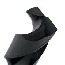
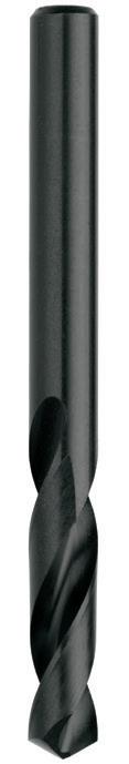
Catalogue Code D186
Discount Group A1002
Material HSS
Surface Finish Blu
Sutton Designation Ferrous Materials
Geometry R30 Point
0100 1.0 26 6 D186 0100 0110 1.1 28 7 D186 0110
0120 1.2 30 8 D186 0120
0130 1.3 30 8 D186 0130
0140 1.4 32 9 D186 0140
0150 1.5 32 9 D186 0150
0160 1.6 34 10 D186 0160
0170 1.7 34 10 D186 0170
0180 1.8 36 11 D186 0180
0190 1.9 36 11 D186 0190
0200 2.0 38 12 D186 0200
0210 2.1 40 13 D186 0210
0220 2.2 40 13 D186 0220
0230 2.3 40 13 D186 0230
0240 2.4 43 14 D186 0240
0250 2.5 43 14 D186 0250
0260 2.6 43 14 D186 0260
0270 2.7 46 16 D186 0270
0280 2.8 46 16 D186 0280
0290 2.9 46 16 D186 0290
0300 3.0 46 16 D186 0300
0310 3.1 49 18 D186 0310
0320 3.2 49 18 D186 0320
0330 3.3 49 18 D186 0330
0340 3.4 52 20 D186 0340
0350 3.5 52 20 D186 0350
0360 3.6 52 20 D186 0360
0370 3.7 52 20 D186 0370
0380 3.8 55 22 D186 0380
0390 3.9 55 22 D186 0390
0400 4.0 55 22 D186 0400
0410 4.1 55 22 D186 0410
0420 4.2 55 22 D186 0420
0430 4.3 58 24 D186 0430
0440 4.4 58 24 D186 0440
0450 4.5 58 24 D186 0450
0460 4.6 58 24 D186 0460
0470 4.7 58 24
0470 0480 4.8 62 26
4.9 62 26
0480
0490
36
D186
D186
0500 5.0 62 26 D186 0500 0510 5.1 62 26 D186 0510 0520 5.2 62 26 D186 0520 0530 5.3 62 26 D186 0530 0540 5.4 66 28 D186 0540 0550 5.5 66 28 D186 0550 0560 5.6 66 28 D186 0560 0570 5.7 66 28 D186 0570 0580 5.8 66 28 D186 0580 0590 5.9 66 28 D186 0590 0600 6.0 66 28 D186 0600 0610 6.1 70 31 D186 0610 0620 6.2 70 31 D186 0620 0630 6.3 70 31 D186 0630 0640 6.4 70 31 D186 0640 0650 6.5 70 31 D186 0650 0660 6.6 70 31 D186 0660 0670 6.7 70 31 D186 0670 0680 6.8 74 34 D186 0680 0690 6.9 74 34 D186 0690 0700 7.0 74 34 D186 0700 0710 7.1 74 34 D186 0710 0720 7.2 74 34 D186 0720 0730 7.3 74 34 D186 0730 0740 7.4 74 34 D186 0740 0750 7.5 74 34 D186 0750 0760 7.6 79 37 D186 0760 0770 7.7 79 37 D186 0770 0780 7.8 79 37 D186 0780 0790 7.9 79 37 D186 0790 0800 8.0 79 37 D186 0800 0810 8.1 79 37 D186 0810 0820 8.2 79 37 D186 0820 0830 8.3 79 37 D186 0830 0840 8.4 79 37 D186 0840 0850 8.5 79 37 D186 0850 0860 8.6 84 40 D186 0860 0870 8.7 84 40 D186 0870 0880 8.8 84 40 D186 0880 0890 8.9 84 40 D186 0890 P Steel M Stainless Steel K Cast Iron N Non-Ferrous Metals S Titanium & Super Alloys H Hard Materials D186 VDI 3323 ISO • 1 P • 2 • 3 • 4 • 5 • 6 • 7 • 8 9 • 10 11 12 13 • 14.1 M • 14.2 14.3 • 15 K • 16 • 17 • 18 • 19 • 20 • 21 N • 22 23 24 25 26 27 28 • 29 30 31 S 32 33 34 35 36 37.1 37.2 37.3 37.4 37.5 • Optimal • Effective 38.1 H 38.2 39.1 39.2 • 40 41
D186
0490
Blu
Drills Stub,
118° Form C >3mm Order Quantity Bulk 10 (5 > 7.5mm) Size Ref. d1 (h8) l1 l2 Item # Size Ref. d1 (h8) l1 l2 Item # 36 Contents Index
Type
- Rigid twist drill
- Self centring point geometry
- For use in automatic lathes & hand drilling machines
Code D186
Group A1002
HSS
37 0900 9.0 84 40 D186 0900 0910 9.1 84 40 D186 0910 0920 9.2 84 40 D186 0920 0930 9.3 84 40 D186 0930 0940 9.4 84 40 D186 0940 0950 9.5 84 40 D186 0950 0960 9.6 89 43 D186 0960 0970 9.7 89 43 D186 0970 0980 9.8 89 43 D186 0980 0990 9.9 89 43 D186 0990 1000 10.0 89 43 D186 1000 1010 10.1 89 43 D186 1010 1020 10.2 89 43 D186 1020 1030 10.3 89 43 D186 1030 1040 10.4 89 43 D186 1040 1050 10.5 89 43 D186 1050 1060 10.6 95 47 D186 1060 1070 10.7 95 47 D186 1070 1080 10.8 95 47 D186 1080 1090 10.9 95 47 D186 1090 1100 11.0 95 47 D186 1100 1110 11.1 95 47 D186 1110 1120 11.2 95 47 D186 1120 1130 11.3 95 47 D186 1130 1140 11.4 95 47 D186 1140 1150 11.5 95 47 D186 1150 1160 11.6 95 47 D186 1160 1170 11.7 95 47 D186 1170 1180 11.8 95 47 D186 1180 1190 11.9 102 51 D186 1190 1200 12.0 102 51 D186 1200 1210 12.1 102 51 D186 1210 1220 12.2 102 51 D186 1220 1230 12.3 102 51 D186 1230 1240 12.4 102 51 D186 1240 1250 12.5 102 51 D186 1250 1260 12.6 102 51 D186 1260 1270 12.7 102 51 D186 1270 1280 12.8 102 51 D186 1280 1290 12.9 102 51 D186 1290 1300 13.0 102 51 D186 1300 P Steel M Stainless Steel K Cast Iron N Non-Ferrous Metals S Titanium & Super Alloys H Hard Materials D186 VDI 3323 ISO • 1 P • 2 • 3 • 4 • 5 • 6 • 7 • 8 9 • 10 11 12 13 • 14.1 M • 14.2 14.3 • 15 K • 16 • 17 • 18 • 19 • 20 • 21 N • 22 23 24 25 26 27 28 • 29 30 31 S 32 33 34 35 36 37.1 37.2 37.3 37.4 37.5 • Optimal • Effective 38.1 H 38.2 39.1 39.2 • 40 41
Drills Stub, Blu
Catalogue
Discount
Material
Surface
Sutton Designation Ferrous Materials Geometry R30 Point Type 118° Form C > 3mm Order Quantity Bulk (5) Size Ref. d1 (h8) l1 l2 Item # Size Ref. d1 (h8) l1 l2 Item # Contents Index
Finish Blu
Drills Stub, Blu
- Rigid twist drill
- Self centring point geometry
- For use in automatic lathes & hand drilling machines
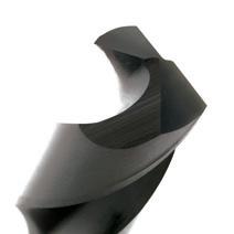
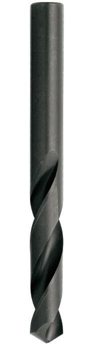
Material HSS
38 0326 3.26 #30 49 24 D126 0326 0409 4.09 #20 54 27 D126 0409 0485 4.85 #11 57 30 D126 0485 P Steel M Stainless Steel K Cast Iron N Non-Ferrous Metals S Titanium & Super Alloys H Hard Materials D126 VDI 3323 ISO • 1 P • 2 • 3 • 4 • 5 • 6 • 7 • 8 9 • 10 11 12 13 • 14.1 M • 14.2 14.3 • 15 K • 16 • 17 • 18 • 19 • 20 • 21 N • 22 23 24 25 26 27 28 • 29 30 31 S 32 33 34 35 36 37.1 37.2 37.3 37.4 37.5 • Optimal • Effective 38.1 H 38.2 39.1 39.2 • 40 41
Catalogue Code D126
Discount Group A1002
Surface Finish Blu
Sutton Designation Ferrous Materials
118°
Order Quantity Bulk 10 (5 > 19/64) Size Ref. d1 (h8) l1 l2 Item # 38 Contents Index
Geometry R30 Point Type
Form C
Drills Long Series
- General purpose drill
- Ideal for long reach type applications
- For deep hole applications, pecking is recommended
- Recommended for controlled machine drilling only
39 0100 1.00 57 29 D113 0100 0110 1.10 57 29 D113 0110 0120 1.20 76 44 D113 0120 0130 1.30 76 44 D113 0130 0140 1.40 76 44 D113 0140 0150 1.50 76 44 D113 0150 0159 1.59 1/16 76 44 D113 0159 0160 1.60 95 51 D113 0160 0170 1.70 95 51 D113 0170 0180 1.80 95 51 D113 0180 0190 1.90 95 51 D113 0190 0198 1.98 5/64 95 51 D113 0198 0200 2.00 108 57 D113 0200 0210 2.10 108 57 D113 0210 0220 2.20 108 57 D113 0220 0230 2.30 108 57 D113 0230 0238 2.38 3/32 108 57 D113 0238 0240 2.40 108 57 D113 0240 0250 2.50 117 64 D113 0250 0260 2.60 117 64 D113 0260 0270 2.70 117 64 D113 0270 0278 2.78 7/64 117 64 D113 0278 0280 2.80 117 64 D113 0280 0290 2.90 117 64 D113 0290 0300 3.00 130 70 D113 0300 0310 3.10 130 70 D113 0310 0318 3.18 1/8 130 70 D113 0318 0320 3.20 130 70 D113 0320 0330 3.30 137 76 D113 0330 0340 3.40 137 76 D113 0340 0350 3.50 137 76 D113 0350 0357 3.57 9/64 137 76 D113 0357 0360 3.60 137 76 D113 0360 0370 3.70 137 76 D113 0370 0380 3.80 137 76 D113 0380 0390 3.90 137 76 D113 0390 0397 3.97 5/32 137 76 D113 0397 0400 4.00 146 86 D113 0400 0410 4.10 146 86 D113 0410 0420 4.20 146 86 D113 0420 P Steel M Stainless Steel K Cast Iron N Non-Ferrous Metals S Titanium & Super Alloys H Hard Materials D113 VDI 3323 ISO • 1 P • 2 • 3 • 4 5 • 6 • 7 8 9 • 10 11 12 13 • 14.1 M 14.2 14.3 • 15 K • 16 • 17 • 18 • 19 • 20 • 21 N • 22 23 24 25 26 27 28 29 30 31 S 32 33 34 35 36 37.1 37.2 37.3 37.4 37.5 • Optimal • Effective 38.1 H 38.2 39.1 39.2 • 40 41
Catalogue Code D113 Discount Group A0502 Material HSS Surface Finish Blu Sutton Designation Long Reach Geometry R30 Point Type 118° Standard Order Quantity Bulk (10) Size Ref. d1 (h8) l1 l2 Item #
39 Contents Index
Drills Long Series
- General purpose drill
- Ideal for long reach type applications
- For deep hole applications, pecking is recommended
- Recommended for controlled machine drilling only
40 0430 4.30 146 86 D113 0430 0437 4.37 11/64 146 86 D113 0437 0440 4.40 146 86 D113 0440 0450 4.50 146 86 D113 0450 0460 4.60 146 86 D113 0460 0470 4.70 146 86 D113 0470 0476 4.76 3/16 146 86 D113 0476 0480 4.80 146 86 D113 0480 0490 4.90 146 86 D113 0490 0500 5.00 152 92 D113 0500 0510 5.10 152 92 D113 0510 0516 5.16 13/64 152 92 D113 0516 0520 5.20 152 92 D113 0520 0530 5.30 152 92 D113 0530 0540 5.40 152 92 D113 0540 0550 5.50 152 92 D113 0550 0556 5.56 7/32 152 92 D113 0556 0560 5.60 152 92 D113 0560 0570 5.70 152 92 D113 0570 0580 5.80 152 92 D113 0580 0590 5.90 152 92 D113 0590 0595 5.95 15/64 156 95 D113 0595 0600 6.00 156 95 D113 0600 0610 6.10 156 95 D113 0610 0620 6.20 156 95 D113 0620 0630 6.30 156 95 D113 0630 0635 6.35 1/4 156 95 D113 0635 0640 6.40 156 95 D113 0640 0650 6.50 159 98 D113 0650 0660 6.60 159 98 D113 0660 0670 6.70 159 98 D113 0670 0676 6.75 17/64 159 98 D113 0676 0680 6.80 159 98 D113 0680 0690 6.90 159 98 D113 0690 0700 7.00 159 98 D113 0700 0710 7.10 159 98 D113 0710 0714 7.14 9/32 159 98 D113 0714 0720 7.20 159 98 D113 0720 0730 7.30 159 98 D113 0730 0740 7.40 159 98 D113 0740 P Steel M Stainless Steel K Cast Iron N Non-Ferrous Metals S Titanium & Super Alloys H Hard Materials D113 VDI 3323 ISO • 1 P • 2 • 3 • 4 5 • 6 • 7 8 9 • 10 11 12 13 • 14.1 M 14.2 14.3 • 15 K • 16 • 17 • 18 • 19 • 20 • 21 N • 22 23 24 25 26 27 28 29 30 31 S 32 33 34 35 36 37.1 37.2 37.3 37.4 37.5 • Optimal • Effective 38.1 H 38.2 39.1 39.2 • 40 41
Catalogue Code D113 Discount Group A0502 Material HSS
Finish Blu
Designation Long Reach Geometry
Point Type 118° Standard Order Quantity Bulk (10) Size Ref. d1 (h8) l1 l2 Item # Contents Index
Surface
Sutton
R30
Drills Long Series
- General purpose drill
- Ideal for long reach type applications
- For deep hole applications, pecking is recommended - Recommended for controlled machine drilling only
41 0750 7.50 162 102 D113 0750 0754 7.54 19/64 162 102 D113 0754 0760 7.60 162 102 D113 0760 0770 7.70 162 102 D113 0770 0780 7.80 162 102 D113 0780 0790 7.90 162 102 D113 0790 0794 7.94 5/16 162 102 D113 0794 0800 8.00 165 105 D113 0800 0810 8.10 165 105 D113 0810 0820 8.20 165 105 D113 0820 0830 8.30 165 105 D113 0830 0833 8.33 21/64 165 105 D113 0833 0840 8.40 165 105 D113 0840 0850 8.50 165 105 D113 0850 0860 8.60 165 105 D113 0860 0870 8.70 165 105 D113 0870 0873 8.73 11/32 165 105 D113 0873 0880 8.80 171 108 D113 0880 0890 8.90 171 108 D113 0890 0900 9.00 171 108 D113 0900 0910 9.10 171 108 D113 0910 0913 9.13 23/64 171 108 D113 0913 0920 9.20 171 108 D113 0920 0930 9.30 171 108 D113 0930 0940 9.40 171 108 D113 0940 0950 9.50 171 108 D113 0950 0953 9.52 3/8 171 108 D113 0953 0960 9.60 171 108 D113 0960 0970 9.70 171 108 D113 0970 0980 9.80 171 108 D113 0980 0990 9.90 171 108 D113 0990 0992 9.92 25/64 178 111 D113 0992 1000 10.00 178 111 D113 1000 1010 10.10 178 111 D113 1010 1020 10.20 178 111 D113 1020 1030 10.30 178 111 D113 1030 1032 10.32 13/32 178 111 D113 1032 1040 10.40 178 111 D113 1040 1050 10.50 184 117 D113 1050 1060 10.60 184 117 D113 1060 P Steel M Stainless Steel K Cast Iron N Non-Ferrous Metals S Titanium & Super Alloys H Hard Materials D113 VDI 3323 ISO • 1 P • 2 • 3 • 4 5 • 6 • 7 8 9 • 10 11 12 13 • 14.1 M 14.2 14.3 • 15 K • 16 • 17 • 18 • 19 • 20 • 21 N • 22 23 24 25 26 27 28 29 30 31 S 32 33 34 35 36 37.1 37.2 37.3 37.4 37.5 • Optimal • Effective 38.1 H 38.2 39.1 39.2 • 40 41
Catalogue Code D113 Discount Group A0502 Material HSS Surface Finish Blu Sutton Designation Long Reach Geometry R30 Point Type 118° Standard Order Quantity Bulk 10 (5 > 7.5mm) Size Ref. d1 (h8) l1 l2 Item # Contents Index
Drills Long Series
- General purpose drill
- Ideal for long reach type applications
- For deep hole applications, pecking is recommended
- Recommended for controlled machine drilling only
42 1070 10.70 184 117 D113 1070 1072 10.72 27/64 184 117 D113 1072 1080 10.80 184 117 D113 1080 1090 10.90 184 117 D113 1090 1100 11.00 184 117 D113 1100 1110 11.10 184 117 D113 1110 1111 11.11 7/16 184 117 D113 1111 1120 11.20 184 117 D113 1120 1130 11.30 184 117 D113 1130 1140 11.40 184 117 D113 1140 1150 11.50 184 117 D113 1150 1151 11.51 29/64 191 121 D113 1151 1160 11.60 184 117 D113 1160 1170 11.70 184 117 D113 1170 1180 11.80 184 117 D113 1180 1190 11.90 184 117 D113 1190 1191 11.91 15/32 191 121 D113 1191 1200 12.00 197 121 D113 1200 1210 12.10 197 121 D113 1210 1220 12.20 197 121 D113 1220 1230 12.30 197 121 D113 1230 1231 12.30 31/64 197 121 D113 1231 1240 12.40 197 121 D113 1240 1250 12.50 197 121 D113 1250 1260 12.60 197 121 D113 1260 1269 12.70 1/2 197 121 D113 1269 1270 12.70 197 121 D113 1270 1280 12.80 203 121 D113 1280 1290 12.90 203 121 D113 1290 1300 13.00 203 121 D113 1300 P Steel M Stainless Steel K Cast Iron N Non-Ferrous Metals S Titanium & Super Alloys H Hard Materials D113 VDI 3323 ISO • 1 P • 2 • 3 • 4 5 • 6 • 7 8 9 • 10 11 12 13 • 14.1 M 14.2 14.3 • 15 K • 16 • 17 • 18 • 19 • 20 • 21 N • 22 23 24 25 26 27 28 29 30 31 S 32 33 34 35 36 37.1 37.2 37.3 37.4 37.5 • Optimal • Effective 38.1 H 38.2 39.1 39.2 • 40 41
Catalogue Code D113 Discount Group A0502 Material HSS Surface Finish Blu Sutton Designation Long Reach Geometry R30 Point Type 118° Standard Order Quantity Bulk (5) Size Ref. d1 (h8) l1 l2 Item # Contents Index
Drills Morse Taper Shank
- General purpose drill
- Suitable for materials up to 900N/mm2
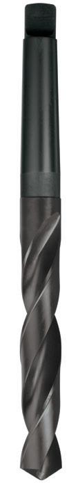
Catalogue Code D115
Discount Group A0702
Material HSS
Surface Finish Blu
Sutton Designation N
Geometry R30
Point Type 118° Form A
Shank Tolerance -
0318 3.18 1/8 117 37 1 D115 0318 0357 3.57 9/64 121 39 1 D115 0357 0397 3.97 5/32 123 43 1 D115 0397 0437 4.37 11/64 128 47 1 D115 0437 0476 4.76 3/16 133 52 1 D115 0476 0516 5.16 13/64 133 52 1 D115 0516 0550 5.50 138 57 1 D115 0550 0556 5.56 7/32 138 57 1 D115 0556 0595 5.95 15/64 138 57 1 D115 0595 0600 6.00 138 57 1 D115 0600 0635 6.35 1/4 144 63 1 D115 0635 0650 6.50 144 63 1 D115 0650 0676 6.75 17/64 144 63 1 D115 0676 0700 7.00 150 69 1 D115 0700 0714 7.14 9/32 150 69 1 D115 0714 0750 7.50 150 69 1 D115 0750
0754 7.54 19/64 156 75 1 D115 0754 0794 7.94 5/16 156 75 1 D115 0794 0800 8.00 156 75 1 D115 0800 0833 8.33 21/64 156 75 1 D115 0833 0850 8.50 156 75 1 D115 0850 0873 8.73 11/32 162 81 1 D115 0873 0900 9.00 162 81 1 D115 0900 0913 9.13 23/64 162 81 1 D115 0913 0950 9.50 162 81 1 D115 0950 0953 9.52 3/8 168 87 1 D115 0953 0992 9.92 25/64 168 87 1 D115 0992
10.00 168 87 1 D115 1000
10.32 13/32 168 87 1 D115 1032
10.50 168 87 1
43
1050 1072 10.72
1100 11.00
1100 1111 11.11
1111 1150
1151
175 94 1 D115 1151 1191 11.91 15/32 182 101 1 D115 1191 1200 12.00 182 101 1 D115 1200 1231 12.30 31/64 182 101 1 D115 1231 1250 12.50 182 101 1 D115 1250 1269 12.70 1/2 182 101 1 D115 1269 1300 13.00 182 101 1 D115 1300 1310 13.10 33/64 182 108 1 D115 1310 1349 13.49 17/32 189 108 1 D115 1349 1350 13.50 189 108 1 D115 1350 1389 13.89 35/64 189 108 1 D115 1389 1400 14.00 189 108 1 D115 1400 1429 14.29 9/16 212 114 2 D115 1429 1450 14.50 212 114 2 D115 1450 1468 14.68 37/64 212 114 2 D115 1468 1500 15.00 212 114 2 D115 1500 1508 15.08 19/32 218 120 2 D115 1508 1548 15.48 39/64 218 120 2 D115 1548 1550 15.50 218 120 2 D115 1550 1588 15.87 5/8 218 120 2 D115 1588 1600 16.00 218 120 2 D115 1600 1627 16.27 41/64 223 125 2 D115 1627 1650 16.50 223 125 2 D115 1650 1667 16.67 21/32 223 125 2 D115 1667 1700 17.00 223 125 2 D115 1700 1707 17.06 43/64 228 130 2 D115 1707 1746 17.46 11/16 228 130 2 D115 1746 1750 17.50 228 130 2 D115 1750 1786 17.86 45/64 228 130 2 D115 1786 1800 18.00 228 130 2 D115 1800 1826 18.26 23/32 233 135 2 D115 1826 1850 18.50 233 135 2 D115 1850 1865 18.65 47/64 233 135 2 D115 1865 1900 19.00 233 135 2 D115 1900 1905 19.05 3/4 238 140 2 D115 1905 1945 19.45 49/64 238 140 2 D115 1945 1950 19.50 238 140 2 D115 1950 1984 19.84 25/32 238 140 2 D115 1984 2000 20.00 238 140 2 D115 2000 2024 20.24 51/64 243 145 2 D115 2024 2050 20.50 243 145 2 D115 2050 2064 20.64 13/16 243 145 2 D115 2064 2100 21.00 243 145 2 D115 2100 2103 21.03 53/64 243 145 2 D115 2103 2143 21.43 27/32 248 150 2 D115 2143 2150 21.50 248 150 2 D115 2150 P Steel M Stainless Steel K Cast Iron N Non-Ferrous Metals S Titanium & Super Alloys H Hard Materials D115 VDI 3323 ISO • 1 P • 2 • 3 • 4 • 5 • 6 • 7 • 8 9 • 10 11 12 13 • 14.1 M 14.2 14.3 • 15 K • 16 • 17 • 18 • 19 • 20 21 N 22 23 24 25 26 27 28 29 30 31 S 32 33 34 35 36 37.1 37.2 37.3 37.4 37.5 • Optimal • Effective 38.1 H 38.2 39.1 39.2 • 40 41
1000
1032
1050
D115
27/64 175 94 1 D115 1072
175 94 1 D115
7/16 175 94 1 D115
11.50 175 94 1 D115 1150
11.51 29/64
Size Ref. d1 (h8) l1 l2 MT # Item # Size Ref. d1 (h8) l1 l2 MT # Item # 43 Contents Index
Drills Morse Taper Shank
2183 21.83 55/64 248 150 2 D115 2183
2200 22.00 248 150 2 D115 2200
2223 22.22 7/8 248 150 2 D115 2223
2250 22.50 253 155 2 D115 2250
2262 22.62 57/64 253 155 2 D115 2262
2300 23.00 253 155 2 D115 2300
2302 23.02 29/32 253 155 2 D115 2302
2342 23.41 59/64 276 155 3 D115 2342
2350 23.50 276 155 3 D115 2350
2381 23.81 15/16 281 160 3 D115 2381
2400 24.00 281 160 3 D115 2400
2421 24.21 61/64 281 160 3 D115 2421
2450 24.50 281 160 3 D115 2450
2461 24.61 31/32 281 160 3 D115 2461
2500 25.00 281 160 3 D115 2500
2501 25.00 63/64 286 165 3 D115 2501
2540 25.40 1" 286 165 3 D115 2540
2550 25.50 286 165 3 D115 2550
2580 25.80 1-1/64 286 165 3 D115 2580
2600 26.00 286 165 3 D115 2600
2619 26.19 1-1/32 286 165 3 D115 2619
2650 26.50 286 165 3 D115 2650
2659 26.59 1-3/64 291 170 3 D115 2659
2699 26.99 1-1/16 291 170 3 D115 2699
2700 27.00 291 170 3 D115 2700
2738 27.38 1-5/64 291 170 3 D115 2738
2750 27.50 291 170 3 D115 2750
2778 27.78 1-3/32 291 170 3 D115 2778
2800 28.00 291 170 3 D115 2800
2818 28.18 1-7/64 296 175 3 D115 2818
2850 28.50 296 175 3 D115 2850
2858 28.57 1-1/8 296 175 3 D115 2858
2897 28.97 1-9/64 296 175 3 D115 2897
2900 29.00 296 175 3 D115 2900
2937 29.36 1-5/32 296 175 3 D115 2937
2950 29.50 296 175 3 D115 2950
2977 29.77 1-11/64 296 175 3 D115 2977
3000 30.00 296 175 3 D115 3000
3016
Catalogue Code D115
Discount Group A0702
Material HSS
Surface Finish Blu
Sutton Designation N
Geometry R30
Point Type 118° Form A
Shank Tolerance -
44
3050
3056 30.56 1-13/64 301 180
3096 30.96 1-7/32 301 180
3100 31.00 301 180 3 D115 3100 3135 31.35 1-15/64 301 180 3 D115 3135 3150 31.50 301 180 3 D115 3150 3175 31.75 1-1/4 306 185 3 D115 3175 3200 32.00 334 185 4 D115 3200 3250 32.50 334 185 4 D115 3250 3300 33.00 334 185 4 D115 3300 3334 33.40 1-5/16 334 185 4 D115 3334 3350 33.50 334 185 4 D115 3350 3400 34.00 339 190 4 D115 3400 3450 34.50 339 190 4 D115 3450 3493 34.92 1-3/8 339 190 4 D115 3493 3500 35.00 339 190 4 D115 3500 3550 35.50 339 190 4 D115 3550 3600 36.00 344 195 4 D115 3600 3650 36.50 344 195 4 D115 3650 3700 37.00 344 195 4 D115 3700 3750 37.50 344 195 4 D115 3750 3800 38.00 349 200 4 D115 3800 3810 38.10 1-1/2 349 200 4 D115 3810 3850 38.50 349 200 4 D115 3850 3900 39.00 349 200 4 D115 3900 3950 39.50 349 200 4 D115 3950 4000 40.00 349 200 4 D115 4000 4050 40.50 354 205 4 D115 4050 4100 41.00 354 205 4 D115 4100 4128 41.27 1-5/8 354 205 4 D115 4128 4150 41.50 354 205 4 D115 4150 4200 42.00 354 205 4 D115 4200 4250 42.50 354 205 4 D115 4250 4300 43.00 359 210 4 D115 4300 4350 43.50 359 210 4 D115 4350 4400 44.00 359 210 4 D115 4400 4405 44.05 1-47/64 359 210 4 • 4445 44.45 1-3/4 359 210 4 D115 4445 4450 44.50 359 210 4 D115 4450 4485 44.85 1-49/64 359 210 4 • 4500 45.00 359 210 4 D115 4500 P Steel M Stainless Steel K Cast Iron N Non-Ferrous Metals S Titanium & Super Alloys H Hard Materials D115 VDI 3323 ISO • 1 P • 2 • 3 • 4 • 5 • 6 • 7 • 8 9 • 10 11 12 13 • 14.1 M 14.2 14.3 • 15 K • 16 • 17 • 18 • 19 • 20 21 N 22 23 24 25 26 27 28 29 30 31 S 32 33 34 35 36 37.1 37.2 37.3 37.4 37.5 • Optimal • Effective 38.1 H 38.2 39.1 39.2 • 40 41 • Available on request as special manufacture. Subject to lead time.
30.16 1-3/16 301 180 3 D115 3016
30.50 301 180 3 D115 3050
3 D115 3056
3 D115 3096
General purpose drill
Suitable for materials up to 900N/mm2
-
-
Size Ref. d1 (h8) l1 l2 MT # Item # Size Ref. d1 (h8) l1 l2 MT # Item # Contents Index
Drills Morse Taper Shank
- General purpose drill
- Suitable for materials up to 900N/mm2
Catalogue Code D115
Discount Group A0702
Material HSS
Surface Finish Blu
Sutton Designation N
Geometry R30
Point Type 118° Form A Shank Tolerance -
45 4550 45.50 364 215 4 D115 4550 4564 45.64 1-51/64 359 210 4 • 4600 46.00 364 215 4 D115 4600 4643 46.43 1-53/64 359 210 4 • 4650 46.50 364 215 4 D115 4650 4700 47.00 364 215 4 D115 4700 4723 47.23 1-55/64 359 210 4 • 4750 47.50 364 215 4 D115 4750 4763 47.63 1-7/8 369 220 4 D115 4763 4800 48.00 369 220 4 D115 4800 4802 48.02 1-57/64 359 210 4 • 4850 48.50 369 220 4 D115 4850 4882 48.82 1-59/64 359 210 4 • 4900 49.00 369 220 4 D115 4900 4950 49.50 369 220 4 D115 4950 4961 49.61 1-61/64 359 210 4 • 5000 50.00 369 220 4 D115 5000 5004 50.04 1-63/64 359 210 4 • 5050 50.50 374 225 4 D115 5050 5080 50.80 2" 374 225 4 D115 5080 5100 51.00 413 225 5 • 5159 51.59 2-1/32 413 225 5 D115 5159 5239 52.39 2-1/16 413 225 5 D115 5239 5398 53.98 2-1/8 413 225 5 D115 5398 5556 55.56 2-3/16 413 225 5 D115 5556 5715 57.15 2-1/4 413 225 5 D115 5715 5874 58.74 2-5/16 413 225 5 D115 5874 6033 60.32 2-3/8 429 241 5 D115 6033 6191 61.91 2-7/16 429 241 5 D115 6191 6350 63.50 2-1/2 432 244 5 D115 6350 6509 65.09 2-9/16 432 244 5 D115 6509 6668 66.67 2-5/8 432 244 5 D115 6668 6985 69.85 2-3/4 432 244 5 D115 6985 7620 76.20 3" 432 244 5 D115 7620 P Steel M Stainless Steel K Cast Iron N Non-Ferrous Metals S Titanium & Super Alloys H Hard Materials D115 VDI 3323 ISO • 1 P • 2 • 3 • 4 • 5 • 6 • 7 • 8 9 • 10 11 12 13 • 14.1 M 14.2 14.3 • 15 K • 16 • 17 • 18 • 19 • 20 21 N 22 23 24 25 26 27 28 29 30 31 S 32 33 34 35 36 37.1 37.2 37.3 37.4 37.5 • Optimal • Effective 38.1 H 38.2 39.1 39.2 • 40 41
• Available on request as special manufacture. Subject to lead time.
Size Ref. d1 (h8) l1 l2 MT # Item # Size Ref. d1 (h8) l1 l2 MT # Item # Contents Index
Drills Morse Taper Shank, Heavy Duty
- General purpose cobalt drill
- Suitable for materials up to 1400N/mm2
- Cobalt content, ensures high abrasion resistance
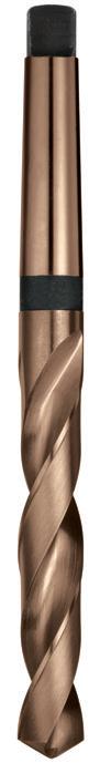
Catalogue Code D141
Discount Group A0702
Material HSS Co
Surface Finish
Colour Temp
Sutton Designation Tough Materials
Geometry R30
Point Type 118° Form A
Shank Tolerance -
46 1000 10.00 168 87 1 D141 1000 1050 10.50 168 87 1 D141 1050 1100 11.00 175 94 1 D141 1100 1150 11.50 175 94 1 D141 1150 1200 12.00 182 101 1 D141 1200 1250 12.50 182 101 1 D141 1250 1300 13.00 182 101 1 D141 1300 1350 13.50 189 108 1 D141 1350 1400 14.00 189 108 1 D141 1400 1450 14.50 212 114 2 D141 1450 1500 15.00 212 114 2 D141 1500 1550 15.50 218 120 2 D141 1550 1600 16.00 218 120 2 D141 1600 1650 16.50 223 125 2 D141 1650 1700 17.00 223 125 2 D141 1700 1750 17.50 228 130 2 D141 1750 1800 18.00 228 130 2 D141 1800 1850 18.50 233 135 2 D141 1850 1900 19.00 233 135 2 D141 1900 1950 19.50 238 140 2 D141 1950 2000 20.00 238 140 2 D141 2000 2050 20.50 243 145 2 D141 2050 2100 21.00 243 145 2 D141 2100 2150 21.50 248 150 2 D141 2150 2200 22.00 248 150 2 D141 2200 2250 22.50 253 155 2 D141 2250 2300 23.00 253 155 2 D141 2300 2350 23.50 276 155 3 D141 2350 2400 24.00 281 160 3 D141 2400 2450 24.50 281 160 3 D141 2450 2500 25.00 281 160 3 D141 2500 2550 25.50 286 165 3 D141 2550 2600 26.00 286 165 3 D141 2600 2650 26.50 286 165 3 D141 2650 2700 27.00 291 170 3 D141 2700 2750 27.50 291 170 3 D141 2750 2800 28.00 291 170 3 D141 2800 2850 28.50 296 175 3 D141 2850 2900 29.00 296 175 3 D141 2900 2950 29.50 296 175 3 D141 2950 3000 30.00 296 175 3 D141 3000 3050 30.50 301 180 3 D141 3050 3100 31.00 301 180 3 D141 3100 3150 31.50 301 180 3 D141 3150 3200 32.00 334 185 4 D141 3200 P Steel M Stainless Steel K Cast Iron N Non-Ferrous Metals S Titanium & Super Alloys H Hard Materials D141 VDI 3323 ISO • 1 P • 2 • 3 • 4 • 5 • 6 • 7 • 8 9 • 10 11 • 12 13 • 14.1 M • 14.2 • 14.3 • 15 K • 16 • 17 • 18 • 19 • 20 • 21 N • 22 • 23 • 24 25 • 26 • 27 • 28 29 30 31 S 32 33 34 35 36 37.1 37.2 37.3 37.4 37.5 • Optimal • Effective 38.1 H 38.2 39.1 39.2 • 40 41
Size Ref. d1 (h8) l1 l2 MT # Item #
46 Contents Index
Drills Morse Taper Shank, Long Series
- General purpose drill
- For long reach applications
- Suitable for materials up to 900N/mm2
47 1000 10.00 197 116 1 D140 1000 1050 10.50 197 116 1 D140 1050 1100 11.00 206 125 1 D140 1100 1150 11.50 206 125 1 D140 1150 1200 12.00 215 134 1 D140 1200 1250 12.50 215 134 1 D140 1250 1300 13.00 215 134 1 D140 1300 1350 13.50 223 142 1 D140 1350 1400 14.00 223 142 1 D140 1400 1450 14.50 245 147 2 D140 1450 1500 15.00 245 147 2 D140 1500 1550 15.50 251 153 2 D140 1550 1600 16.00 251 153 2 D140 1600 1650 16.50 257 159 2 D140 1650 1700 17.00 257 159 2 D140 1700 1750 17.50 263 165 2 D140 1750 1800 18.00 263 165 2 D140 1800 1850 18.50 269 171 2 D140 1850 1900 19.00 269 171 2 D140 1900 1950 19.50 275 177 2 D140 1950 2000 20.00 275 177 2 D140 2000 2050 20.50 282 184 2 D140 2050 2100 21.00 282 184 2 D140 2100 2200 22.00 289 191 2 D140 2200 2300 23.00 296 198 2 D140 2300 2400 24.00 327 206 3 D140 2400 2500 25.00 327 206 3 D140 2500 2600 26.00 335 214 3 D140 2600 2800 28.00 343 222 3 D140 2800 3000 30.00 351 230 3 D140 3000 3200 32.00 397 248 4 D140 3200 P Steel M Stainless Steel K Cast Iron N Non-Ferrous Metals S Titanium & Super Alloys H Hard Materials D140 VDI 3323 ISO • 1 P • 2 • 3 • 4 • 5 • 6 • 7 • 8 9 • 10 11 12 13 • 14.1 M • 14.2 14.3 • 15 K • 16 • 17 • 18 • 19 • 20 21 N 22 23 24 25 26 27 28 29 30 31 S 32 33 34 35 36 37.1 37.2 37.3 37.4 37.5 • Optimal • Effective 38.1 H 38.2 39.1 39.2 • 40 41
Catalogue Code D140 Discount Group A0702 Material HSS Surface Finish Blu Sutton Designation N Geometry R30 Point Type 118° Standard Shank ToleranceSize Ref. d1 (h8) l1 l2 MT # Item #
47 Contents Index
Drills Morse Taper Accessories
Morse Taper Sleeve
- Hardened alloy steel
- Precision ground internally and externally
Drill Drift key - to eject Morse Taper drills from sleeves, sockets and machine spindles
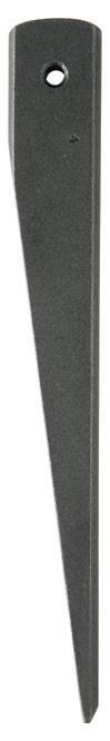
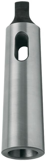
Inside Morse Taper Outside Morse Taper
48 0012 1 2 17.780 92 17 12.065 D118 0012 0013 1 3 23.825 99 5 12.065 D118 0013 0023 2 3 23.825 112 18 17.78 D118 0023 0014 (1)* 4 31.267 124 6.5 12.065 D118 0014 0024 2 4 31.267 124 6.5 17.78 D118 0024 0034 3 4 31.267 140 22.5 23.825 D118 0034 0015 (1)* 5 44.399 156 6.5 12.065 D118 0015 0025 (2)* 5 44.399 156 6.5 17.78 D118 0025 0035 3 5 44.399 156 6.5 23.825 D118 0035 0045 4 5 44.399 171 21.5 31.267 D118 0045 0036 3 6 63.348 218 8 23.825 D118 0036 0046 4 6 63.348 218 8 31.267 D118 0046 0056 5 6 63.348 218 8 44.399 D118 0056 MT1 MT #1 & #2 D142 MT1 MT3 MT #3 D142 MT3 MT4 MT #4 D142 MT4 a
Catalogue Code D142 D118 Discount Group A0702 A0702 Material - Alloyed Steel Surface Finish Brt Brt Sutton Designation Drift Sleeve Geometry -Point Type -Shank Tolerance -Size Ref. MT # (internal) MT # (external) d1 l1 a1 d2 Item # Item #
*The use of sizes where inside taper is shown in brackets should be avoided wherever possible
48 48 Contents Index
Drills Reduced Shank
- General purpose drill with reduced shank
- Standard point geometry
- Designed for machine and hand held drilling
- Overall and flute lengths do not include drill point

1310 13.10 33/64 152 86 D188 1310 1349 13.49 17/32 152 86 D188 1349 1350 13.5 152 86 D188 1350 1389 13.89 35/64 152 86 D188 1389 1400 14.0 152 86 D188 1400 1429 14.29 9/16 152 86 D188 1429 1450 14.5 152 86 D188 1450 1468 14.68 37/64 152 86 D188 1468 1500 15.0 152 86 D188 1500 1508 15.08 19/32 152 86 D188 1508 1548 15.48 39/64 152 86 D188 1548 1550 15.5 152 86 D188 1550 1588 15.87 5/8 152 86 D188 1588 1600 16.0 152 86 D188 1600 1627 16.27 41/64 152 86 D188 1627 1650 16.5 152 86 D188 1650 1667 16.67 21/32 152 86 D188 1667 1700 17.0 152 86 D188 1700 1707 17.06 43/64 152 86 D188 1707 1746 17.46 11/16 152 86 D188 1746 1786 17.86 45/64 152 86 D188 1786 1750 17.5 152 86 D188 1750 1826 18.26 23/32 152 86 D188 1826 1865 18.65 47/64 152 86 D188 1865 1800 18.0 152 86 D188 1800 1850 18.5 152 86 D188 1850 1900 19.0 152 86 D188 1900 1905 19.05 3/4 152 86 D188 1905 1945 19.45 49/64 152 86 D188 1945
19.5 152 86 D188 1950
19.84 25/32 152 86 D188 1984
20.0 152 86 D188 2000
20.24 51/64 152 86 D188 2024
20.5 152 86 D188 2050 2064 20.64 13/16 152 86
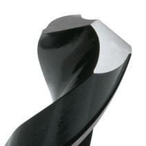

Catalogue Code D188
Discount Group A0906
Material HSS
Surface Finish Blu
Sutton Designation N
Geometry R30
Point Type 118° Standard Shank 12.5mm
Sets (Discount group A1202)
RS4 5/8, 3/4, 7/8, 1" D188 RS4
RS4M 16, 18, 22, 25mm
S8R 9/16, 5/8, 11/16, 3/4, 13/16, 7/8, 15/16, 1"
SM8R 14, 15, 16, 16.5 , 18, 20, 22, 25mm
RS16 17/32, 9/16,19/32, 5/8, 21/32, 11/16, 23/32, 3/4, 5/32, 13/16, 27/32, 7/8, 29/32, 15/16, 31/32, 1"
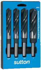
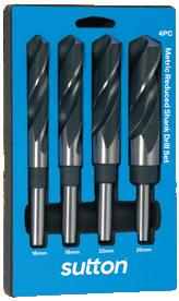
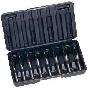
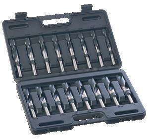
49
1984
2000
2024
2100 21.0
2143 21.43
2150 21.5
2200
2223
2223 2250 22.5 152 86 D188 2250 2300 23.0 152 86 D188 2300 2302 23.02 29/32 152 86 D188 2302 2350 23.5 152 86 D188 2350 2381 23.81 15/16 152 86 D188 2381 2400 24.0 152 86 D188 2400 2450 24.5 152 86 D188 2450 2461 24.61 31/32 152 86 D188 2461 2500 25.0 152 86 D188 2500 2540 25.40 1 152 86 D188 2540 2600 26.0 152 86 D188 2600 2699 26.99 1-1/16 152 86 D188 2699 2800 28.0 152 86 D188 2800 2858 28.57 1-1/8 152 86 D188 2858 3000 30.0 152 86 D188 3000 3016 30.16 1-3/16 152 86 D188 3016 3175 31.75 1-1/4 152 86 D188 3175
1950
2050
D188 2064
152 86 D188 2100
27/32 152 86 D188 2143
152 86 D188 2150
22.0 152 86 D188 2200
22.22 7/8 152 86 D188
D188 RS4M
D188
D188
S8R
SM8R
D188 RS16 P Steel M Stainless Steel K Cast Iron N Non-Ferrous Metals S Titanium & Super Alloys H Hard Materials D188 D120 VDI 3323 ISO • • 1 P • • 2 • • 3 • • 4 • • 5 • • 6 • • 7 • • 8 9 • • 10 11 12 13 • • 14.1 M • • 14.2 14.3 • • 15 K 16 • • 17 18 • • 19 20 • • 21 N • • 22 • • 23 • • 24 25 • • 26 • • 27 • • 28 29 30 31 S 32 33 34 35 36 37.1 37.2 37.3 37.4 37.5 • Optimal • Effective 38.1 H 38.2 39.1 39.2 • • 40 41 D188 RS4 D188 RS4M D188 RS16 D188 SM8R *Not available once current stock is depleted
Size Ref. d1 (h8) l1 l2 Item # Size Ref. d1 (h8) l1 l2 Item # 49 49 Contents Index
Drills Panel, Single Ended
- Rigid design for through hole drilling
- Ideal for rivet holes in sheet metal fabrication
- Recommended for shallow holes no deeper than 1-1/4 x d1
Drills Panel, Double Ended
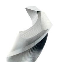
- Double ended rigid design for through hole drilling
- Ideal for rivet holes in sheet metal fabrication
- Recommended for shallow holes no deeper than 1-1/4 x d1
- Tupoint drills require fully tightened chuck jaws
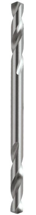
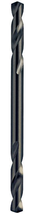
50 P Steel M Stainless Steel K Cast Iron N Non-Ferrous Metals S Titanium & Super Alloys H Hard Materials D125 D124 / D126 D122 D121 / D123 VDI 3323 ISO • • • • 1 P • • • • 2 • • • • 3 • • • • 4 5 • • • • 6 • • 7 8 9 • • 10 11 12 13 • • • • 14.1 M • • • • 14.2 14.3 • • • • 15 K 16 • • • • 17 18 19 20 • • 21 N • • 22 • • 23 • • 24 25 • • 26 27 • • 28 29 30 31 S 32 33 34 35 36 37.1 37.2 37.3 37.4 37.5 • Optimal • Effective 38.1 H 38.2 39.1 39.2 • • • • 40 41 0318 3.18 1/8 54 19 3.18 3.00 D121 0318 D124 0318 0326 3.26 # 30 54 19 3.26 3.18 (1/8") D121 0326 D124 0326 0409 4.09 # 20 54 22 4.09 3.97 (5/32") D121 0409 D124 0409 0485 4.85 # 11 54 22 4.85 4.76 (3/16") D121 0485 D124 0485 Stub 118° Point (Discount Group A1002) D123 D126 0326 3.26 # 30 49 24 3.26 3.18 (1/8") D123 0326 D126 0326 0409 4.09 # 20 54 27 4.09 3.97 (5/32") D123 0409 D126 0409 0485 4.85 # 11 57 30 4.85 4.76 (3/16") D123 0485 D126 0485 0318 3.18 1/8 54 19 3.18 3.00 D122 0318 D125 0318 0326 3.26 # 30 54 19 3.26 3.18 (1/8") D122 0326 D125 0326 0409 4.09 # 20 54 22 4.09 3.97 (5/32") D122 0409 D125 0409 0485 4.85 # 11 54 22 4.85 4.76 (3/16") D122 0485 D125 0485
Catalogue Code D121 D124 Discount Group A0802 A0802 Material HSS HSS Surface Finish Brt Blu Sutton Designation Non Ferrous Ferrous Geometry -Point Type 135° Standard 135° Standard Packaging & Order Quantity Bulk (10) Bulk (10) Size Ref. d1 (h8) l1 l2 d2 Rivet Size Item # Item #
Catalogue Code D122 D125 Discount Group A0802 A0802 Material HSS HSS Surface Finish Brt Blu Sutton Designation Non Ferrous Ferrous Geometry -Point Type 135° Standard 135° Standard Packaging & Order Quantity Bulk (10) Bulk (10) Size Ref. d1 (h8) l1 l2 d2 Rivet Size Item # Item #
50 50 50 50 Contents Index
Drills Panel, Double Ended
- Double ended rigid design for through hole drilling
- Ideal for rivet holes in sheet metal fabrication
- Recommended for shallow holes no deeper than 1-1/4 x
- Tupoint drills require fully tightened chuck jaws
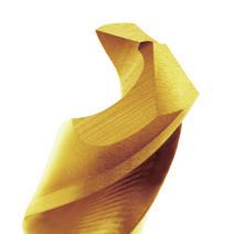
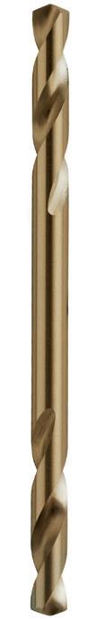
51 0318 3.18 1/8 54 19 3.18 3.00 D130 0318 0326 3.26 # 30 54 19 3.26 3.18 (1/8") D130 0326 0409 4.09 # 20 54 22 4.09 3.97 (5/32") D130 0409 0485 4.85 # 11 54 22 4.85 4.76 (3/16") D130 0485 P Steel M Stainless Steel K Cast Iron N Non-Ferrous Metals S Titanium & Super Alloys H Hard Materials D130 VDI 3323 ISO • 1 P • 2 • 3 • 4 • 5 • 6 • 7 • 8 • 9 • 10 • 11 • 12 • 13 • 14.1 M • 14.2 14.3 • 15 K 16 • 17 18 • 19 • 20 21 N 22 23 24 25 26 27 28 29 30 31 S 32 33 34 35 36 37.1 37.2 37.3 37.4 37.5 • Optimal • Effective 38.1 H 38.2 39.1 39.2 • 40 41
d1
Catalogue Code D130 Discount Group A0802 Material HSS Co Surface Finish Colour Temp Sutton Designation Tough Steels GeometryPoint Type 135° Standard Packaging & Order Quantity Bulk (10) Size Ref. d1 (h8) l1 l2 d2 Rivet Size Item # 51 51 51 Contents Index
Drills Centre
- Ensures
Refer
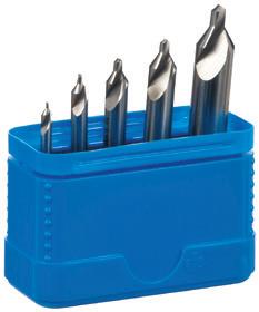
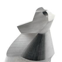
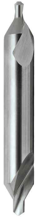
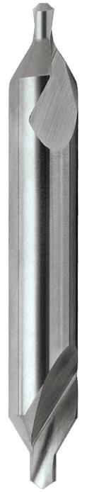
52 Type A 0080 0.80 0.80 25.00 1.10 3.15 D135 0080 0100 1.00 1.00 31.50 1.30 3.15 D135 0100 0125 1.25 1.25 31.50 1.60 3.15 D135 0125 0160 1.60 1.60 35.50 2.00 4.00 D135 0160 0200 2.00 2.00 40.00 2.50 5.00 D135 0200 0250 2.50 2.50 45.00 3.10 6.30 D135 0250 0315 3.15 3.15 50.00 3.90 8.00 D135 0315 0400 4.00 4.00 56.00 5.00 10.00 D135 0400 0500 5.00 5.00 63.00 6.30 12.50 D135 0500 0630 6.30 6.30 71.00 8.00 16.00 D135 0630 0800 8.00 8.00 80.00 10.10 20.00 D135 0800 1000 10.00 10.00 100.00 12.80 25.00 D135 1000 Plain Type 0001 # 1 3/64 1-1/4 3/64 1/8 D136 0001 0002 # 2 5/64 1-7/8 5/64 3/16 D136 0002 0003 # 3 7/64 2 7/64 1/4 D136 0003 0004 # 4 1/8 2-1/8 1/8 5/16 D136 0004 0005 # 5 3/16 2-3/4 3/16 7/16 D136 0005 0006 # 6 7/32 3 7/32 1/2 D136 0006 0007 # 7 1/4 3-1/4 1/4 5/8 D136 0007 0008 # 8 5/16 3-1/2 5/16 3/4 D136 0008 Set - 5 Pce SCD1 #1, #2, #3, #4 & #5
SCD1 P Steel M Stainless Steel K Cast Iron N Non-Ferrous Metals S Titanium & Super Alloys H Hard Materials D136 D135 VDI 3323 ISO • • 1 P • • 2 • • 3 • • 4 5 • • 6 7 8 9 10 11 12 13 • • 14.1 M • • 14.2 14.3 • • 15 K 16 • • 17 18 19 20 • • 21 N • • 22 • • 23 • • 24 25 • • 26 27 • • 28 • • 29 30 31 S 32 33 34 35 36 37.1 37.2 37.3 37.4 37.5 • Optimal • Effective 38.1 H 38.2 39.1 39.2 40 41
D136
60° centre
in the end of shafts
accurate starting and centring
precision
Catalogue Code D135 D136 Discount Group A0302 A0302 Material HSS HSS Surface Finish Brt Brt Sutton Designation N N Geometry A Type Plain Type Point Type 60° 60° Standard DIN 333 ANSI B94-11 Size Ref. Type d1 l1 l2 d2 Item # Item # D136 SCD1 Contents Index
- For drilling
holes
for
-
to Carbide Drill section for VHM Centre Drills
Drills NC Spotting
- Precision drill for machine use
- Rigid design for “seat” position accuracy
- 90° offers hole chamfering & spotting with the one tool
- 120° for spotting, matching a typical drill point
- Only drill to the depth of the point
- Refer to Carbide Drill section for VHM Spotting Drills
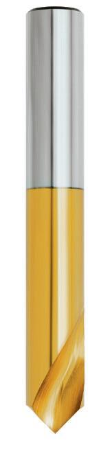
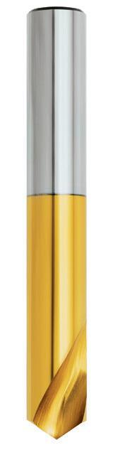
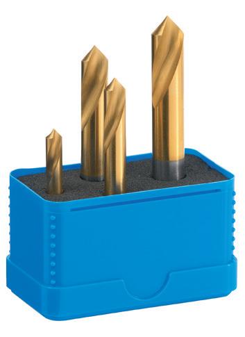
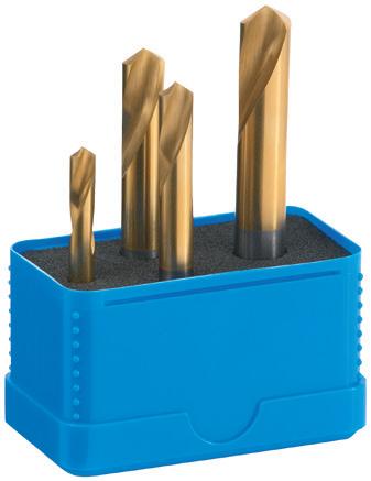
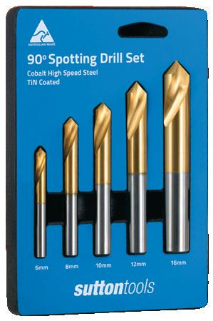
53 0300 3.0 49 16 3.0 D175 0300 D176 0300 0400 4.0 55 22 4.0 D175 0400 D176 0400 0500 5.0 62 25 5.0 D175 0500 D176 0500 0600 6.0 66 25 6.0 D175 0600 D176 0600 0800 8.0 79 29 8.0 D175 0800 D176 0800 1000 10.0 89 32 10.0 D175 1000 D176 1000 1200 12.0 102 32 12.0 D175 1200 D176 1200 1600 16.0 115 35 16.0 D175 1600 D176 1600 2000 20.0 131 37 20.0 D175 2000 D176 2000 2500 25.0 151 37 25.0 D175 2500 D176 2500 Sets 0004 6.0, 8.0, 10.0 & 12.0 4 D175 0004 D176 0004 SDT5 6.0, 8.0, 10.0, 12.0 & 16.0 5 D175 SDT5 P Steel M Stainless Steel K Cast Iron N Non-Ferrous Metals S Titanium & Super Alloys H Hard Materials D176 D175 VDI 3323 ISO • • 1 P • • 2 • • 3 • • 4 • • 5 • • 6 • • 7 • • 8 9 • • 10 11 • • 12 • • 13 • • 14.1 M • • 14.2 • • 14.3 • • 15 K • • 16 • • 17 • • 18 • • 19 • • 20 • • 21 N • • 22 • • 23 • • 24 • • 25 • • 26 • • 27 • • 28 • • 29 30 • • 31 S • • 32 • • 33 • • 34 35 36 • • 37.1 • • 37.2 37.3 • • 37.4 37.5 • Optimal • Effective • • 38.1 H 38.2 39.1 39.2 • • 40 41 D175 0004 D176 0004 D175 SDT5
Catalogue Code D175 D176 Discount Group A1124 A1124 Material HSS Co HSS Co Surface Finish TiN TiN Sutton Designation N N Geometry -Point Type 90° 120° Shank Tolerance -Size Ref. d1 (h8) l1 l2 d2 Pieces Item # Item # 90° 120° Contents Index
Tool Bits Turning & Machining
M2 HSS
- Recommended for turning or machining of low-alloy and free-machining steels and most non-ferrous materials.
M42 CoHSS
- Can withstand high cutting speeds
- Especially suited to production turning of high alloy steels and other materials
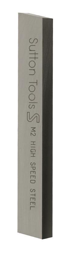
54 0472 3/16 2-1/2 M301 0472 0473 3/16 3 M302 0473 0632 1/4 2-1/2 M301 0632 M302 0632 0633 1/4 3 M302 0633 0634 1/4 4 M302 0634 0792 5/16 2-1/2 M301 0792 M302 0792 0793
M302 0793 0794 5/16 4 M302 0794 0953 3/8 3 M301 0953 M302 0953 0954 3/8 4 M302 0954 0956 3/8 6 M302 0956 1274 1/2 4 M301 1274 M302 1274 1276 1/2 6 M302 1276 1584 5/8 4-1/2 M301 1584 M302 1584 1905 3/4 5 M302 1905 2547 1 7 M302 2547
5/16 3
Catalogue Code M302 Discount Group Z0802 Z0802 Material M2 HSS M42 CoHSS Surface Finish Brt Brt Geometry Square Square Order Quantity 1 1 Size Ref. Size Length Item # Item # 54 54 Contents Index
Tool Bits Turning & Machining
M2 HSS
- Recommended for turning or machining of low-alloy and free-machining steels and most non-ferrous materials.
M42 CoHSS
- Can withstand high cutting speeds - Especially suited to production turning of high alloy steels and other materials
55 0233 3/32 3 M300 0233* 0313 1/8 3 M300 0313* 0474 3/16 4 M300 0474 0634 1/4 4 M300 0634 0794 5/16 4 M300 0794 0954 3/8 4 M300 0954 1114 7/16 4 M300 1114* 1274 1/2 4 M300 1274 1274 1/2 4-1/2 3/32 M304 1274 1584 5/8 5 3/32 M304 1584 1906 3/4 6 1/8 M304 1906 2227 7/8 7 1/8 M304 2227 2548 1 8 3/16 M304 2548 * Not available once current stock is depleted Catalogue Code M300 M304* Discount Group Z0802 Z0802 Material M2 HSS M35 CoHSS Surface Finish Brt Brt Geometry Round Bevel Order Quantity 5 1 Size Ref. Size Length Width Item # Item #
55 55 Contents Index
56 Contents Index
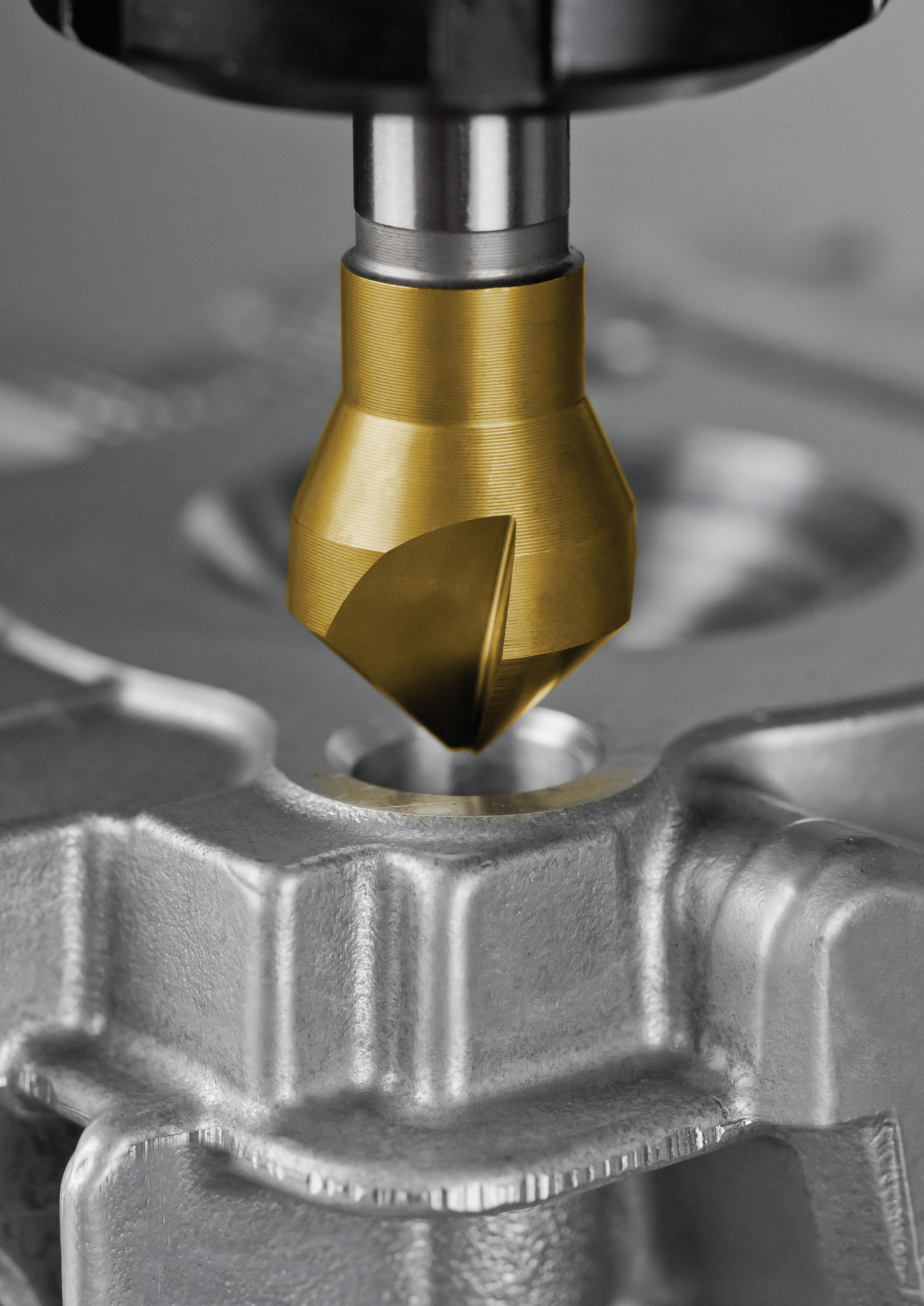
COUNTERSINKS
Counterbores
•
•
•
•
Cross Hole
Single Flute
Three Flute
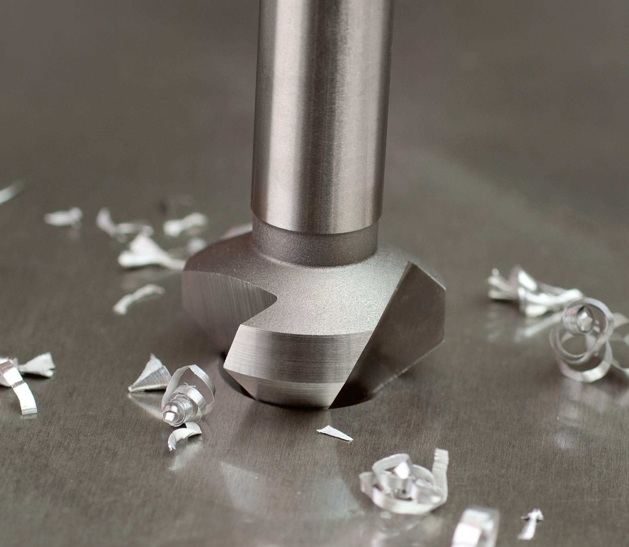
Smooth Cutting… Perfect Chamfering
Catalogue Code: C107
This new generation of countersink applies the three most important areas for optimal tool life in its design.
Constant rake angle along the entire cutting face, latest developments in coating and superior tool material.
• De-burring
• Countersinking / Counterboring screw holes
• Chamfering of tapping holes
• For use in machine applications
Features
• 5% Cobalt grade
High Speed Steel
• Constant flute rake along entire cutting face
• Axial and radial adjusted relief
Higher dimensional precision
• Improved and sharper cutting edge
Benefits
• Chatter-free countersinking and de-burring
• Longer lasting
• Excellent chip flow
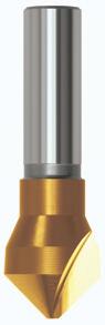
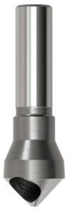
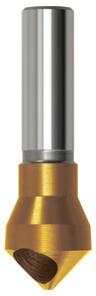
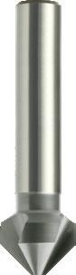
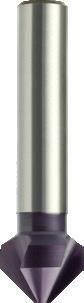
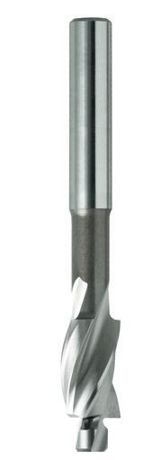
59 Countersinks Finder • Optimal • Effective Page 60 60 61 61 62 62 63 63 64 Catalogue Code C105 C106 C103 C104 C101 C102 C107 C108 C100 Material HSS HSS HSS HSS Co HSS Co Surface Finish Brt TiN Brt TiN Brt TiN Brt TiAlN Brt Sutton Designation N N N N UNI N Standard Sutton Standard Sutton Standard Sutton Standard DIN 335 DIN 373 Depth of Cut - - - -Shank Tolerance - - - h9 h6 ISO VDI^ 3323 Material Condition HB N/mm2 P 1 Steel - Non-alloy, cast & free cutting ~ 0.15 %C A 125 440 • • • • • • • • • 2 ~ 0.45 %C A 190 640 • • • • • • • • • 3 QT 250 840 • • • • • • • • • 4 ~ 0.75 %C A 270 910 • • • • • • • • • 5 QT 300 1010 • • • • • • 6 Steel - Low alloy & cast < 5% of alloying elements A 180 610 • • • • • • • • • 7 QT 275 930 • • • • • • • • • 8 QT 300 1010 • • • • • • 9 QT 350 1180 • • • • 10 Steel - High alloy, cast & tool A 200 680 • • • • • • • • • 11 HT 325 1100 • • • • 12 Steel - Corrosion resistant & cast Ferritic / Martensitic A 200 680 • • • • • 13 Martensitic QT 240 810 • • • • M 14.1 Stainless Steel Austenitic AH 180 610 • • • • • • 14.2 Duplex 250 840 • • • • • • 14.3 Precipitation Hardening 250 840 • • • • • • K 15 Cast Iron - Grey (GG) Ferritic / Pearlitic 180 610 • • • • • • • • • 16 Pearlitic 260 880 • • • • • • • • • 17 Cast Iron - Nodular (GGG) Ferritic 160 570 • • • • • • • • • 18 Pearlitic 250 840 • • • • • • • • • 19 Cast Iron - Malleable Ferritic 130 460 • • • • • • • • • 20 Pearlitic 230 780 • • • • • N 21 Aluminum & Magnesium - wrought alloy Non Heat Treatable 60 210 • • • • • • • • • 22 Heat Treatable AH 100 360 • • • • • • • • • 23 Aluminum & Magnesium - cast alloy ≤12% Si Non Heat Treatable 75 270 • • • • • • • • • 24 Heat Treatable AH 90 320 • • • • • • • • • 25 Al & Mg - cast alloy >12% Si Non Heat Treatable 130 460 • • 26 Copper & Cu alloys (Brass/Bronze) Free cutting, Pb > 1% 110 390 • • • • • • • • • 27 Brass (CuZn, CuSnZn) 90 320 • • • • • • 28 Bronze (CuSn) 100 360 • • • • • • • • 29 Non-metallic - Thermosetting & fiber-reinforced plastics • • 30 Non-metallic - Hard rubber, wood etc. S 31 High temp. alloys Fe based A 200 680 • • 32 AH 280 950 • • 33 Ni / Co based A 250 840 • • 34 AH 350 1180 • 35 C 320 1080 • 36 Titanium & Ti alloys CP Titanium 400 MPa • • 37.1 Alpha alloys 860 MPa • • 37.2 Alpha / Beta alloys A 960 MPa • • 37.3 AH 1170 MPa • 37.4 Beta alloys A 830 MPa • • 37.5 AH 1400 MPa • H 38.1 Hardened steel HT 45 HRC 38.2 HT 55 HRC 39.1 HT 58 HRC 39.2 HT 62 HRC 40 Cast Iron Chilled C 400 1350 • • • • • • • • • 41 HT 55 HRC Condition: A (Annealed), AH (Age Hardened), C (Cast), HT (Hardened & Tempered), QT (Quenched & Tempered) ISO VDI Material Group Sutton P A Steel N UNI M R Stainless Steel VA K F Cast Iron GG N N Non-Ferrous Metals, Aluminiums & Coppers AI W S S Titaniums & Super Alloys Ti Ni H H Hard Materials (≥ 45 HRC) H ^ VDI 3323 material groups can also be determined by referring to the material cross
the application guide at the back
this catalogue. For expert tooling
go
www.suttonhps.com Contents Index
reference listing in
of
recommendations,
to:
Countersinks Three Flute, 90°
- Countersinking tool
- For machine use
- For use on most materials including plastics,
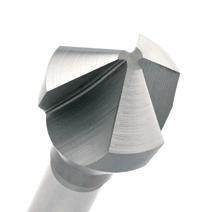
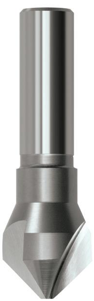
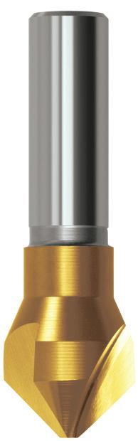
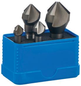
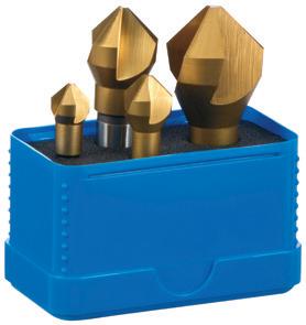
60 60 60 P Steel M Stainless Steel K Cast Iron N Non-Ferrous Metals S Titanium & Super Alloys H Hard Materials C106 C105 VDI 3323 ISO • • 1 P • • 2 • • 3 • • 4 • 5 • • 6 • • 7 • 8 9 • • 10 11 12 13 • 14.1 M • 14.2 • 14.3 • • 15 K • • 16 • • 17 • • 18 • • 19 • 20 • • 21 N • • 22 • • 23 • • 24 25 • • 26 • • 27 • • 28 29 30 31 S 32 33 34 35 36 37.1 37.2 37.3 37.4 37.5 • Optimal • Effective 38.1 H 38.2 39.1 39.2 • • 40 41 0901 4-10mm 43 6.35 (1/4) C105 0901 C106 0901 0902 4-14mm 48 6.35 (1/4) C105 0902 C106 0902 0903 5-20mm 67 12.7 (1/2) C105 0903 C106 0903 0904 6-28mm 72 12.7 (1/2) C105 0904 C106 0904 0905 6-37mm 89 12.7 (1/2) C105 0905 C106 0905 Set STF1 0901, 0902, 0903, 0904 4 C105 STF1 STF1T 0901, 0902, 0903, 0904 4
STF1T
C106
C106 STF1T
C105 STF1
non-ferrous & ferrous metals
Catalogue Code C105 C106 Discount Group A1106 A1108 Material HSS HSS Surface Finish Brt TiN Sutton Designation N N Geometry -Point Type 90° 90° Shank Tolerance -Size Ref. Range l1 d2 Pieces Item # Item # Contents Index
Countersinks Single Flute, 90°
- Countersinking tool
- For use in portable drills or drilling machines
- For use on most materials including plastics, non-ferrous & ferrous metals
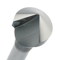
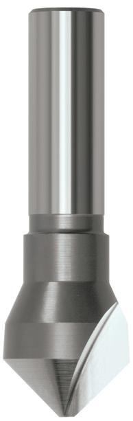
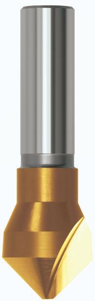
61 61 61 P Steel M Stainless Steel K Cast Iron N Non-Ferrous Metals S Titanium & Super Alloys H Hard Materials C104 C103 VDI 3323 ISO • • 1 P • • 2 • • 3 • • 4 • 5 • • 6 • • 7 • 8 • 9 • • 10 • 11 • 12 • 13 • 14.1 M • 14.2 • 14.3 • • 15 K • • 16 • • 17 • • 18 • • 19 • 20 • • 21 N • • 22 • • 23 • • 24 25 • • 26 • 27 • • 28 29 30 31 S 32 33 34 35 36 37.1 37.2 37.3 37.4 37.5 • Optimal • Effective 38.1 H 38.2 39.1 39.2 • • 40 41 0901 4-10mm 43 6.35 (1/4) C103 0901 C104 0901 0902 4-14mm 48 6.35 (1/4) C103 0902 C104 0902 0903 5-20mm 67 12.7 (1/2) C103 0903 C104 0903 0904 6-28mm 72 12.7 (1/2) C103 0904
Catalogue Code C103 C104 Discount Group A1106 A1108 Material HSS HSS Surface Finish Brt TiN Sutton Designation N N Geometry -Point Type 90° 90° Shank Tolerance -Size Ref. Range l1 d2 Item # Item # Contents Index
Countersinks Deburring Cross Hole, 90°
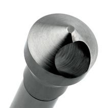
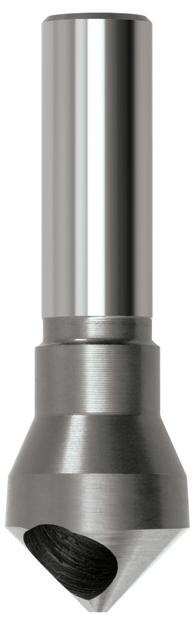
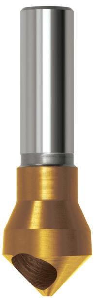
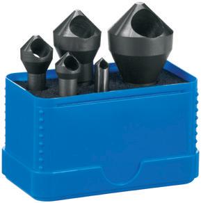
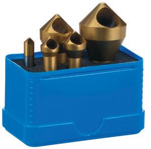
62 62 62 P Steel M Stainless Steel K Cast Iron N Non-Ferrous Metals S Titanium & Super Alloys H Hard Materials C102 C101 VDI 3323 ISO • • 1 P • • 2 • • 3 • • 4 • 5 • • 6 • • 7 • 8 • 9 • • 10 • 11 • 12 • 13 • 14.1 M • 14.2 • 14.3 • • 15 K • • 16 • • 17 • • 18 • • 19 • 20 • • 21 N • • 22 • • 23 • • 24 25 • • 26 • 27 • 28 29 30 31 S 32 33 34 35 36 37.1 37.2 37.3 37.4 37.5 • Optimal • Effective 38.1 H 38.2 39.1 39.2 • • 40 41 0901 3-6mm 45 6.35 (1/4) Double Ended C101 0901 C102 0901 0902 4-10mm 43 6.35 (1/4) C101 0902 C102 0902 0903 5-13mm 48 6.35 (1/4) C101 0903 C102 0903 0904 8-20mm 67 12.7 (1/2) C101 0904 C102 0904 0905 14-28mm 72 12.7 (1/2) C101 0905 C102 0905 0906 13-37mm 89 12.7 (1/2) C101 0906 C102 0906 Set SC1 0901, 0902, 0903, 0904, 0905 5 C101 SC1 SC1T 0901, 0902, 0903, 0904, 0905 5 C102 SC1T
C102 SC1T
- Deburring tool - Smooth cutting action Catalogue Code C101 C102 Discount Group A1106 A1108 Material HSS HSS Surface Finish Brt TiN Sutton Designation N N Geometry -Point Type 90° 90° Shank Tolerance -Size Ref. Range l1 d2 Pieces Item # Item #
C101 SC1
Contents Index
Countersinks Three Flute, 90°, DIN 335
- De-burring
- Countersinking / Counterboring screw holes - Chamfering of tapping holes
- For use in machine applications Type N - For non-ferrous, - Type UNI - For difficult to machine materials
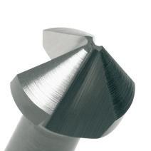
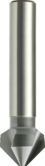

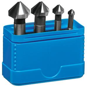
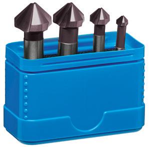
63 0430 4.3 M2 40 4 1.3 C107 0430 C108 0430 0530 5.3 M2.5 40 4 1.5 C107 0530 C108 0530 0630 6.3 M3 45 5 1.5 C107 0630 C108 0630 0730 7.3 M3.5 50 6 1.8 C107 0730 C108 0730 0800 8.0 50 6 2.0 C107 0800 C108 0800 0840 8.4 M4 50 6 2.0 C107 0840 C108 0840 0940 9.4 M5 50 6 2.2 C107 0940 C108 0940 1000 10.0 50 6 2.5 C107 1000 C108 1000 1040 10.4 50 6 2.5 C107 1040 C108 1040 1150 11.5 M6 56 8 2.8 C107 1150 C108 1150 1240 12.4 56 8 2.8 C107 1240 C108 1240 1340 13.4 56 8 2.9 C107 1340 C108 1340 1500 15.0 60 10 3.2 C107 1500 C108 1500 1650 16.5 M8 60 10 3.2 C107 1650 C108 1650 1900 19.0 M10 63 10 3.5 C107 1900 C108 1900 2050 20.5 63 10 3.5 C107 2050 C108 2050 2300 23.0 67 10 3.8 C107 2300 C108 2300 2500 25.0 67 10 3.8 C107 2500 C108 2500 3000 30.0 71 12 4.2 C107 3000 C108 3000 3100 31.0 71 12 4.2 C107 3100 C108 3100 Set 0004 6.3, 10.4, 16.5, 20.5 4 C107 0004 C108 0004 •
964,
966, 7513, 7516 • For Countersunk screws acc. to ISO 2009, 2010, 7046-1, 7046-2, 7047 C107 0004 C108 0004 P Steel M Stainless Steel K Cast Iron N Non-Ferrous Metals S Titanium & Super Alloys H Hard Materials C108 C107 VDI 3323 ISO • • 1 P • • 2 • • 3 • • 4 • • 5 • • 6 • • 7 • • 8 • 9 • • 10 • 11 • • 12 • 13 • • 14.1 M • • 14.2 • • 14.3 • • 15 K • • 16 • • 17 • • 18 • • 19 • 20 • • 21 N • • 22 • • 23 • • 24 • • 25 • • 26 • • 27 • • 28 • • 29 30 • • 31 S • • 32 • • 33 • 34 • 35 • • 36 • • 37.1 • • 37.2 • 37.3 • • 37.4 • 37.5 • Optimal • Effective 38.1 H 38.2 39.1 39.2 • • 40 41
For Countersunk screws acc. to DIN 963,
965,
Catalogue Code C107 C108 Discount Group A1106 A1108 Material HSS Co HSS Co Surface Finish Brt TiAlN Sutton Designation N UNI Geometry -Point Type 90° 90° Shank Tolerance h9 h9 Size Ref. d1 Screw Head l1 d2 d3 Pieces Item # Item # DIN 335 Contents Index
Countersinks Counterbore
- Solid pilot style
- 3 flute design
- Right-hand cutting
- Nominal size to suit metric socket head cap screws
- Cobalt High Speed Steel enables counterboring in high alloy steels
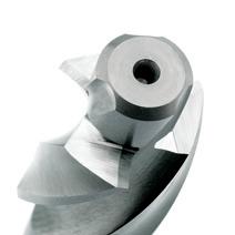

Catalogue Code C100
Discount Group B0709
Material HSS Co
Surface Finish Brt
Sutton Designation N GeometryPoint TypeShank Tolerance h6
64 64 P Steel M Stainless Steel K Cast Iron N Non-Ferrous Metals S Titanium & Super Alloys H Hard Materials C100 VDI 3323 ISO • 1 P • 2 • 3 • 4 • 5 • 6 • 7 • 8 • 9 • 10 • 11 • 12 • 13 • 14.1 M • 14.2 • 14.3 • 15 K • 16 • 17 • 18 • 19 • 20 • 21 N • 22 • 23 • 24 25 • 26 27 • 28 29 30 31 S 32 33 34 35 36 37.1 37.2 37.3 37.4 37.5 • Optimal • Effective 38.1 H 38.2 39.1 39.2 • 40 41 0300 3.0 3.2 6.0 71.0 14.0 5.0 C100 0300 0400 4.0 4.3 8.0 71.0 14.0 5.0 C100 0400 0500 5.0 5.3 10.0 80.0 18.0 8.0
0500 0600 6.0 6.4 11.0 80.0 18.0 8.0 C100 0600 0800 8.0 8.4 15.0 100.0 22.0 12.5 C100 0800 1000 10.0 10.5 18.0 100.0 22.0 12.5 C100 1000 1200 12.0 13.0 20.0 100.0 22.0 12.5 C100 1200
C100
Size Ref. Size d3 d1 l1 l2 d2 Item # d3 Contents Index
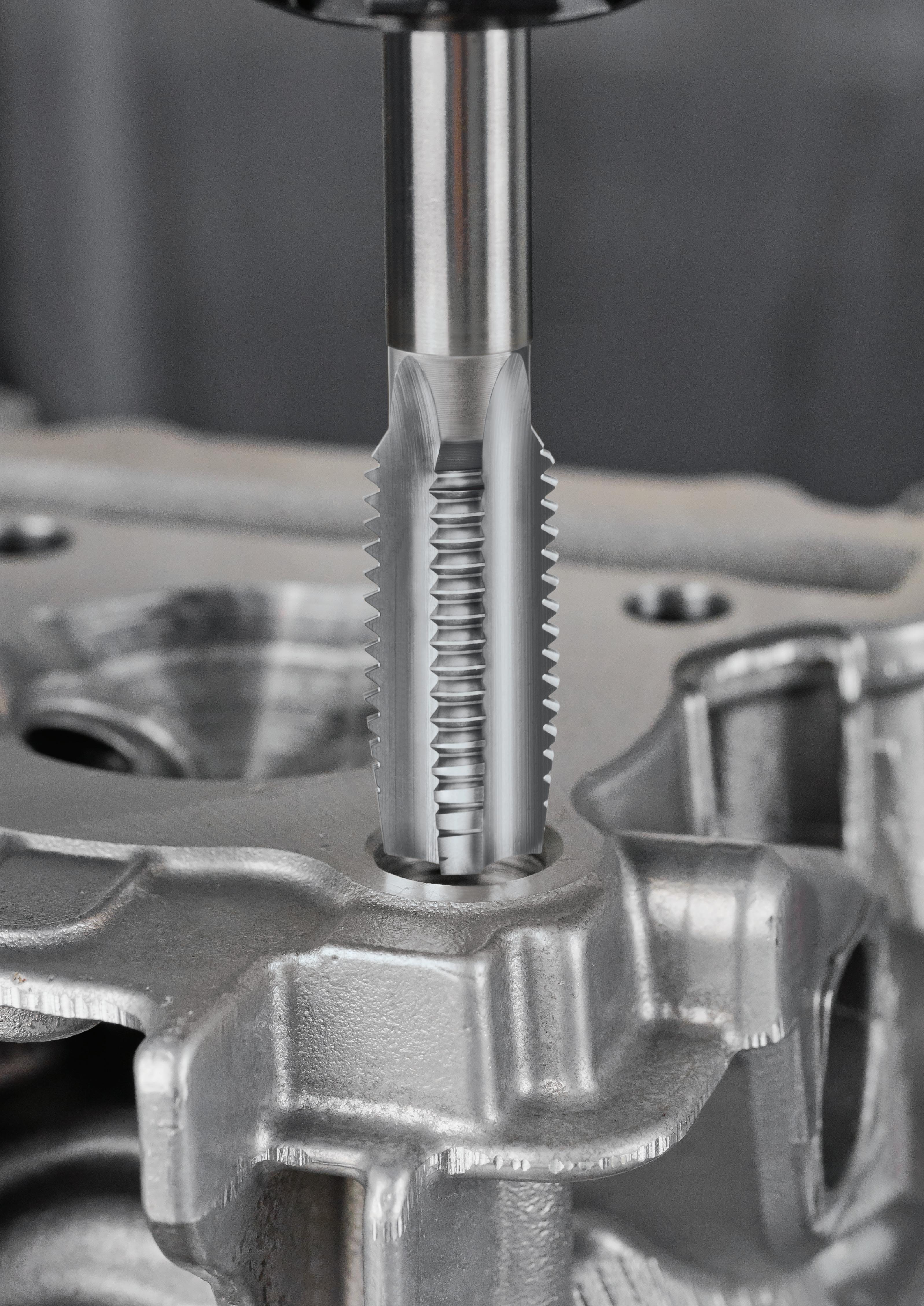
ISO TAPS
• M, MF • UNC, UNF, UNEF, UN, UNS • BSW, BSF, BA, BSB
• Rc (BSPT), Rp (BSPPL), Pg Series, G (BSPF) • NPT, NPTF, NPSF

Special Taps Express Delivery Service…
Sutton Tools is a leading international Manufacturer of specialist cutting tools and is renowned for producing high performance, precision cutting tools specifically designed to individual customer requirements.
With comprehensive customer service and warehouse facilities, our Express Delivery Service enables us to meet your requirements more efficiently than ever before.
All Thread Forms
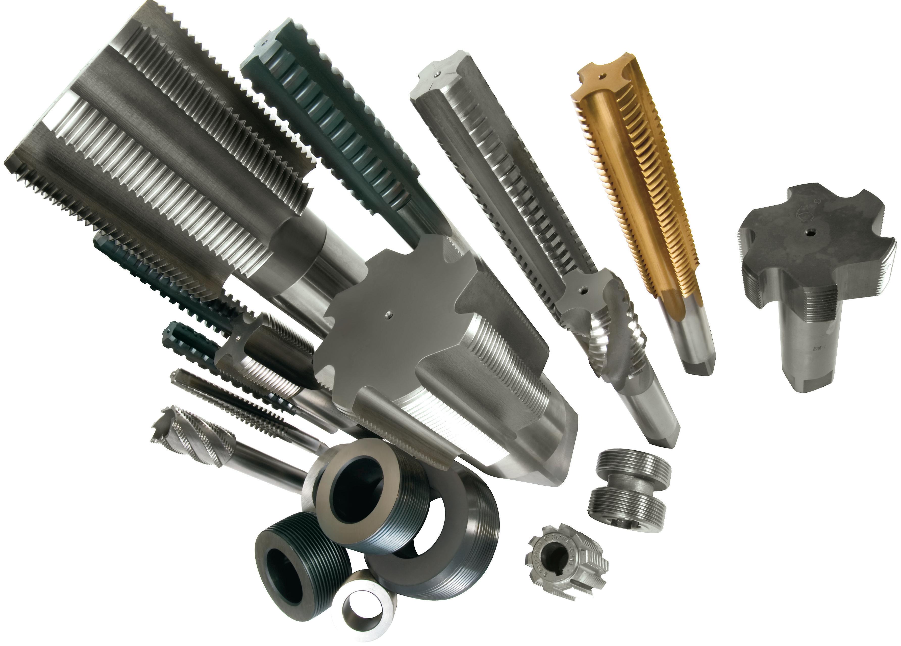
UN, Metric, UNJC, UNJF, MJ, UH, Pg, Whit, Rope forms & Acme and more!!
With our state of the art CNC grinding equipment almost any profile can be achieved. Feel free to discuss these with our Tech team.
*For
Within 24 hours*
Straight Flute Taps M3 to M127
• Spiral Taps M3 to M36
Within 48 Hours*
• Gun Taps M3 to M36
Within 5 Working Days*
Surface Finishes and Treatments:
• Steam Oxide
• Gas Nitride
• Titanium Nitride
• Chromium Nitride
Titanium Carbo-Nitride
• Titanium Aluminium Nitride
orders received prior to 12pm (Australian Eastern Standard Time)
groups
also be determined by referring to the material cross reference listing in the application guide at the back of this catalogue. For expert tooling recommendations, go to: www.suttonhps.com
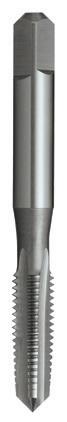
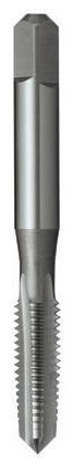
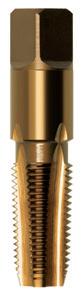
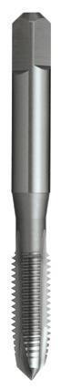
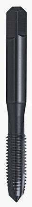
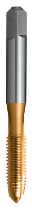
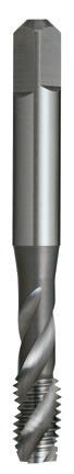
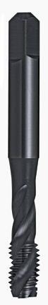
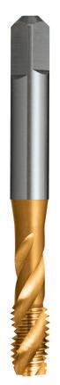
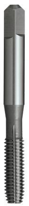
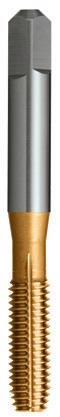
67 Page M 68 70 71 72 72 73 74 74 75 76 76 MF 77 79 79 80 81 81 UNC 82 84 91 86 86 87 88 88 89 90 90 UNF 92 94 98 98 99 100 100 101 BSW 104 106 112 107 107 108 109 109 110 111 111 BSF, BA,
113 G (BSPF) 115 117 115 116 Rc
118 118 118 119 Material HSS HSS HSS HSS HSS HSSE HSSE HSSE Surface Finish Brt Brt Brt Brt TiN Colour Temp Brt Blu TiN Brt Blu TiN Brt TiN Sutton Designation N N-LH 0/Size Nut N N N N N Tapping Depth ≤ 1xØ ≤ 1xØ ≤ 2xØ - - ≤ 3xØ ≤ 2.5xØ ≤ 1.5xØ ISO VDI^ 3323 Material Condition HB N/mm2 P 1 Steel - Non-alloy, cast & free cutting ~ 0.15 %C A 125 440 • • • • • • • • • • • • • • • 2 ~ 0.45 %C A 190 640 • • • • • • • • • • • • • • • 3 QT 250 840 • • • • • • • • • • • • • • • 4 ~ 0.75 %C A 270 910 • • • • • • • • • • • • • • • 5 QT 300 1010 • • • 6 Steel - Low alloy & cast < 5% of alloying elements A 180 610 • • • • • • • • • • • • • • • 7 QT 275 930 • • • • • • • • • • • • • 8 QT 300 1010 • • • 9 QT 350 1180 10 Steel - High alloy, cast & tool A 200 680 • • • 11 HT 325 1100 12 Steel - Corrosion resistant & cast Ferritic / Martensitic A 200 680 • • • • 13 Martensitic QT 240 810 • • M 14.1 Stainless Steel Austenitic AH 180 610 • • • • • • • • • • 14.2 Duplex 250 840 • • • • • • 14.3 Precipitation Hardening 250 840 K 15 Cast Iron - Grey (GG) Ferritic / Pearlitic 180 610 • • • • • • • 16 Pearlitic 260 880 17 Cast Iron - Nodular (GGG) Ferritic 160 570 • • • • • • • • • • • • • 18 Pearlitic 250 840 • • • • • • 19 Cast Iron - Malleable Ferritic 130 460 • • • • • • • • • • 20 Pearlitic 230 780 N 21 Aluminum & Magnesium - wrought alloy Non Heat Treatable 60 210 • • • • • • • • • • • • • 22 Heat Treatable AH 100 360 • • • • • • • • • • • • • 23 Aluminum & Magnesium - cast alloy ≤12% Si Non Heat Treatable 75 270 • • • • • • • • • • • • • 24 Heat Treatable AH 90 320 • • • • • • • • • • • • • 25 Al & Mg - cast alloy >12% Si Non Heat Treatable 130 460 • • 26 Copper & Cu alloys (Brass/Bronze) Free cutting, Pb > 1% 110 390 • • • • • • • • • • • • 27 Brass (CuZn, CuSnZn) 90 320 • • • • • • 28 Bronze (CuSn) 100 360 • • • • • • • • • • 29 Non-metallic - Thermosetting & fiber-reinforced plastics 30 Non-metallic - Hard rubber, wood etc. S 31 High temp. alloys Fe based A 200 680 32 AH 280 950 33 Ni / Co based A 250 840 34 AH 350 1180 35 C 320 1080 36 Titanium & Ti alloys CP Titanium 400 MPa 37.1 Alpha alloys 860 MPa 37.2 Alpha / Beta alloys A 960 MPa 37.3 AH 1170 MPa 37.4 Beta alloys A 830 MPa 37.5 AH 1400 MPa H 38.1 Hardened steel HT 45 HRC 38.2 HT 55 HRC 39.1 HT 58 HRC 39.2 HT 62 HRC 40 Cast Iron Chilled C 400 1350 • • • • • • 41 HT 55 HRC Condition: A (Annealed), AH (Age Hardened), C (Cast), HT (Hardened & Tempered), QT (Quenched & Tempered) • Optimal • Effective ISO VDI Material Group Sutton P A Steel N UNI M R Stainless Steel VA K F Cast Iron GG N N Non-Ferrous Metals, Aluminiums & Coppers AI W S S Titaniums & Super Alloys Ti Ni H H Hard Materials (≥ 45 HRC) H ^ VDI 3323
ISO Taps Finder Contents
BSB (Brass)
(BSPT), Rp (BSPPL), Pg, NPT, NPTF, NPSF
material
can
ISO Taps Metric, Straight Flute,
- General purpose use
- Suitable for materials up to 1000N/mm2
- Through & blind holes
- Suitable for both hand and machine operations
14 piece set (intermediate)
Taps: M3, M4, M5, M6, M8, M10, M12
2.5, 3.3, 4.2, 5.0, 6.8, 8.5, 10.2mm
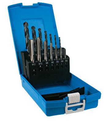
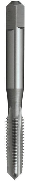
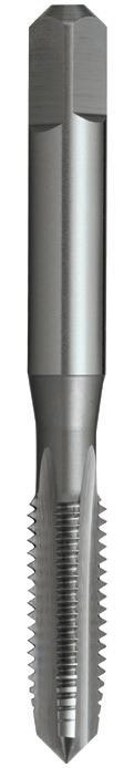
68 68 P Steel M Stainless Steel K Cast Iron N Non-Ferrous Metals S Titanium & Super Alloys H Hard Materials T385 T384 VDI 3323 ISO • • 1 P • • 2 • • 3 • • 4 5 • • 6 • • 7 8 9 10 11 12 13 14.1 M 14.2 14.3 • • 15 K 16 • • 17 18 • • 19 20 • • 21 N • • 22 • • 23 • • 24 25 • • 26 27 • • 28 29 30 31 S 32 33 34 35 36 37.1 37.2 37.3 37.4 37.5 • Optimal • Effective 38.1 H 38.2 39.1 39.2 40 41 0200 M 2 x 0.4 41 8 - 2.50 2.00 4 3 1.6 T384 0200 T385 0200 0250 M 2.5 x 0.45 45 10 - 2.80 2.24 5 3 2.05 T384 0250 T385 0250 0300 M 3 x 0.5 48 11 15 3.15 2.50 5 3 2.5 T384 0300 T385 0300 0350 M 3.5 x 0.6 50 13 17.5 3.55 2.80 5 3 2.9 T384 0350 T385 0350 0400 M 4 x 0.7 53 13 18 4.00 3.15 6 3 3.3 T384 0400 T385 0400 0450 M 4.5 x 0.75 53 13 19 4.50 3.55 6 3 3.7 T384 0450 T385 0450 0500 M 5 x 0.8 58 16 22 5.00 4.00 7 3 4.2 T384 0500 T385 0500 0600 M 6 x 1 66 19 26 6.30 5.00 8 3 5.0 T384 0600 T385 0600 0700 M 7 x 1 66 19 26 7.10 5.60 8 4 6.0 T384 0700 T385 0700 0800 M 8 x 1.25 72 22 30 8.00 6.30 9 4 6.8 T384 0800 T385 0800 0900 M 9 x 1.25 72 22 31 9.00 7.10 10 4 7.8 T384 0900 T385 0900 1000 M 10 x 1.5 80 24 34 10.00 8.00 11 4 8.5 T384 1000 T385 1000 1100 M 11 x 1.5 85 25 - 8.00 6.30 9 4 9.5 T384 1100 T385 1100 1200 M 12 x 1.75 89 29 - 9.00 7.10 10 4 10.2 T384 1200 T385 1200 1400 M 14 x 2 95 30 - 11.20 9.00 12 4 12.0 T384 1400 T385 1400 1600 M 16 x 2 102 32 - 12.50 10.00 13 4 14.0 T384 1600 T385 1600 1800 M 18 x 2.5 112 37 - 14.00 11.20 14 4 15.5 T384 1800 T385 1800 2000 M 20 x 2.5 112 37 - 14.00 11.20 14 4 17.5 T384 2000 T385 2000 2200 M 22 x 2.5 118 38 - 16.00 12.50 16 4 19.5 T384 2200 T385 2200 2400 M 24 x 3 130 45 - 18.00 14.00 18 4 21.0 T384 2400 T385 2400 2700 M 27 x 3 135 45 - 20.00 16.00 20 4 24.0 T384 2700 T385 2700 3000 M 30 x 3.5 138 48 - 20.00 16.00 20 4 26.5 T384 3000 T385 3000 3300 M 33 x 3.5 151 51 - 22.40 18.00 22 4 29.5 T384 3300 T385 3300 3600 M 36 x 4 162 57 - 25.00 20.00 24 4 32.0 T384 3600 T385 3600 3900 M 39 x 4 170 60 - 28.00 22.40 26 4 35.0 T384 3900 T385 3900 4200 M 42 x 4.5 170 60 - 28.00 22.40 26 4 37.5 T384 4200 T385 4200 4500 M 45 x 4.5 187 67 - 31.50 25.00 28 4 40.5 T384 4500 T385 4500 4800 M 48 x 5 187 67 - 31.50 25.00 28 4 43.0 T384 4800 T385 4800 5200 M 52 x 5 200 70 - 35.50 28.00 31 4 47.0 T384 5200 T385 5200 0014 T385 0014
T385 0014
- Depths up to approx. 1 x d1
Catalogue Code T384 T385 Discount Group D0702 D0702 Material HSS HSS Surface Finish Brt Brt Sutton Designation N N Geometry -Chamfer Taper Intermediate Limit & Nut Tolerance ISO 2 / 6H ISO 2 / 6H Size Ref. d1 Pitch l1 l2 l3 d2 sq l4 z drill ø Item # Item #
N
Tap & Drill Sets
M Contents Index
Drills:
-
ISO Taps Metric, Straight Flute, N

Tap & Drill Sets
28 piece set (taper, inter, bott) (Discount Group Z0304)
Taps: M3, M4, M5, M6, M8, M10, M12
Drills: 2.5, 3.3, 4.2, 5.0, 6.8, 8.5, 10.2mm
69 0200 M 2 x 0.4 41 8 - 2.50 2.00 4 3 1.6 T386 0200 T901 0200 0250 M 2.5 x 0.45 45 10 - 2.80 2.24 5 3 2.05 T386 0250 T901 0250 0300 M 3 x 0.5 48 11 15 3.15 2.50 5 3 2.5 T386 0300 T901 0300 0350 M 3.5 x 0.6 50 13 17.5 3.55 2.80 5 3 2.9 T386 0350 T901 0350 0400 M 4 x 0.7 53 13 18 4.00 3.15 6 3 3.3 T386 0400 T901 0400 0450 M 4.5 x 0.75 53 13 19 4.50 3.55 6 3 3.7 T386 0450 T901 0450 0500 M 5 x 0.8 58 16 22 5.00 4.00 7 3 4.2 T386 0500 T901 0500 0600 M 6 x 1 66 19 26 6.30 5.00 8 3 5.0 T386 0600 T901 0600 0700 M 7 x 1 66 19 26 7.10 5.60 8 4 6.0 T386 0700 T901 0700 0800 M 8 x 1.25 72 22 30 8.00 6.30 9 4 6.8 T386 0800 T901 0800 0900 M 9 x 1.25 72 22 31 9.00 7.10 10 4 7.8 T386 0900 T901 0900 1000 M 10 x 1.5 80 24 34 10.00 8.00 11 4 8.5 T386 1000 T901 1000 1100 M 11 x 1.5 85 25 - 8.00 6.30 9 4 9.5 T386 1100 T901 1100 1200 M 12 x 1.75 89 29 - 9.00 7.10 10 4 10.2 T386 1200 T901 1200 1400 M 14 x 2 95 30 - 11.20 9.00 12 4 12.0 T386 1400 T901 1400 1600 M 16 x 2 102 32 - 12.50 10.00 13 4 14.0 T386 1600 T901 1600 1800 M 18 x 2.5 112 37 - 14.00 11.20 14 4 15.5 T386 1800 T901 1800 2000 M 20 x 2.5 112 37 - 14.00 11.20 14 4 17.5 T386 2000 T901 2000 2200 M 22 x 2.5 118 38 - 16.00 12.50 16 4 19.5 T386 2200 T901 2200 2400 M 24 x 3 130 45 - 18.00 14.00 18 4 21.0 T386 2400 T901 2400 2700 M 27 x 3 135 45 - 20.00 16.00 20 4 24.0 T386 2700 • 3000 M 30 x 3.5 138 48 - 20.00 16.00 20 4 26.5 T386 3000 • 3300 M 33 x 3.5 151 51 - 22.40 18.00 22 4 29.5 T386 3300 • 3600 M 36 x 4 162 57 - 25.00 20.00 24 4 32.0 T386 3600 • 3900 M 39 x 4 170 60 - 28.00 22.40 26 4 35.0 T386 3900 • 4200 M 42 x 4.5 170 60 - 28.00 22.40 26 4 37.5 T386 4200 • 4500 M 45 x 4.5 187 67 - 31.50 25.00 28 4 40.5 T386 4500 • 4800 M 48 x 5 187 67 - 31.50 25.00 28 4 43.0 T386 4800 • 5200 M 52 x 5 200 70 - 35.50 28.00 31 4 47.0 T386 5200 • SDT1 T901 SDT1 Steel M Stainless Steel K Cast Iron N Non-Ferrous Metals S Titanium & Super Alloys H Hard Materials T901 T386 VDI 3323 ISO • • 1 P • • 2 • • 3 • • 4 5 • • 6 • • 7 8 9 10 11 12 13 14.1 M 14.2 14.3 • • 15 K 16 • • 17 18 • • 19 20 • • 21 N • • 22 • • 23 • • 24 25 • • 26 27 • • 28 29 30 31 S 32 33 34 35 36 37.1 37.2 37.3 37.4 37.5 • Optimal • Effective 38.1 H 38.2 39.1 39.2 40 41 T901 SDT1 • Available on request as special manufacture. Subject to lead time.
General purpose use
-
Suitable
materials up to 1000N/mm2
for
blind holes
- Through &
both hand and machine operations
- Suitable for
up
approx. 1 x d1
- Depths
to
Catalogue Code T386 T901 Discount Group D0702 D0702 Material HSS HSS Surface Finish Brt Brt Sutton Designation N N Geometry -Chamfer Bottoming Set Limit & Nut Tolerance ISO 2 / 6H ISO 2 / 6H Size Ref. d1 Pitch l1 l2 l3 d2 sq l4 z drill ø Item # Item #
M Contents Index
-
-
ISO Taps Metric, Straight Flute, N, Left Hand
70 70 0300 M 3 x 0.5 48 11 15 3.15 2.50 5 3 2.5 T389 0300 T390 0300 0400 M 4 x 0.7 53 13 18 4.00 3.15 6 3 3.3 T389 0400 T390 0400 0500 M 5 x 0.8 58 16 22 5.00 4.00 7 3 4.2 T389 0500 T390 0500 0600 M 6 x 1 66 19 26 6.30 5.00 8 3 5.0 T389 0600 T390 0600 0800 M 8 x 1.25 72 22 30 8.00 6.30 9 4 6.8 T389 0800 T390 0800 1000 M 10 x 1.5 80 24 34 10.00 8.00 11 4 8.5 T389 1000 T390 1000 1200 M 12 x 1.75 89 29 - 9.00 7.10 10 4 10.2 T389 1200 T390 1200 1400 M 14 x 2 95 30 - 11.20 9.00 12 4 12.0 T389 1400 T390 1400 1600 M 16 x 2 102 32 - 12.50 10.00 13 4 14.0 T389 1600 T390 1600 1800 M 18 x 2.5 112 37 - 14.00 11.20 14 4 15.5 T389 1800 T390 1800 2000 M 20 x 2.5 112 37 - 14.00 11.20 14 4 17.5 T389 2000 T390 2000 P Steel M Stainless Steel K Cast Iron N Non-Ferrous Metals S Titanium & Super Alloys H Hard Materials T390 T389 VDI 3323 ISO • • 1 P • • 2 • • 3 • • 4 5 • • 6 • • 7 8 9 10 11 12 13 14.1 M 14.2 14.3 • • 15 K 16 • • 17 18 • • 19 20 • • 21 N • • 22 • • 23 • • 24 25 • • 26 27 • • 28 29 30 31 S 32 33 34 35 36 37.1 37.2 37.3 37.4 37.5 • Optimal • Effective 38.1 H 38.2 39.1 39.2 40 41
- General purpose use
up to 1000N/mm2
blind holes
Suitable for materials
- Through &
Suitable
up to approx. 1 x d1
for both hand and machine operations - Depths
Catalogue Code T389 T390 Discount Group D0702 D0702 Material HSS HSS Surface Finish Brt Brt Sutton Designation N N Geometry Left Hand Left Hand Chamfer Taper Intermediate Limit & Nut Tolerance ISO 2 / 6H LH ISO 2 / 6H LH Size Ref. d1 Pitch l1 l2 l3 d2 sq l4 z drill ø Item # Item # M Contents Index
ISO Taps Metric, Straight Flute, N, Left Hand
- General purpose use
- Suitable for
- Through & blind holes
- Suitable for both hand and machine operations
- Depths up to approx. 1 x d1
ISO Taps Metric, Straight Flute, Oversize
- Oversize allowance to suit components for galvanize plating
- General purpose use, materials up to 1000N/mm2
- Through & blind holes
- Suitable for both hand and machine operations
- Depths up to approx 1 x d1
- Taper and inter leads available on request
71 71 P Steel M Stainless Steel K Cast Iron N Non-Ferrous Metals S Titanium & Super Alloys H Hard Materials T392 T391 VDI 3323 ISO • • 1 P • • 2 • • 3 • • 4 5 • • 6 • • 7 8 9 10 11 12 13 14.1 M 14.2 14.3 • • 15 K 16 • • 17 18 • • 19 20 • • 21 N • • 22 • • 23 • • 24 25 • • 26 27 • • 28 29 30 31 S 32 33 34 35 36 37.1 37.2 37.3 37.4 37.5 • Optimal • Effective 38.1 H 38.2 39.1 39.2 40 41 0300 M 3 x 0.5 48 11 15 3.15 2.50 5 3 2.5 T391 0300 0400 M 4 x 0.7 53 13 18 4.00 3.15 6 3 3.3 T391 0400 0500 M 5 x 0.8 58 16 22 5.00 4.00 7 3 4.2 T391 0500 0600 M 6 x 1 66 19 26 6.30 5.00 8 3 5.0 T391 0600 0800 M 8 x 1.25 72 22 30 8.00 6.30 9 4 6.8 T391 0800 1000 M 10 x 1.5 80 24 34 10.00 8.00 11 4 8.5 T391 1000 1200 M 12 x 1.75 89 29 - 9.00 7.10 10 4 10.2 T391 1200 1400 M 14 x 2 95 30 - 11.20 9.00 12 4 12.0 T391 1400 1600 M 16 x 2 102 32 - 12.50 10.00 13 4 14.0 T391 1600 1800 M 18 x 2.5 112 37 - 14.00 11.20 14 4 15.5 T391 1800 2000 M 20 x 2.5 112 37 - 14.00 11.20 14 4 17.5 T391 2000 T392 1000 M10 +0.4 x 1.5 85 25 - 8.0 6.3 9.0 4 8.9 T392 1000 1200 M12 +0.4 x 1.75 89 29 - 9.0 7.1 10.0 4 10.6 T392 1200 1600 M16 +0.4 x 2 112 37 - 12.5 10.0 13.0 4 14.4 T392 1600 2000 M20 +0.4 x 2.5 118 38 - 16.0 12.5 16.0 4 17.9 T392 2000 2400 M24 +0.45 x 3 130 45 - 18.0 14.0 18.0 4 21.5 T392 2400
up to 1000N/mm2
materials
Catalogue Code T391 Discount Group D0702 Material HSS
Finish Brt
Limit & Nut Tolerance ISO 2 / 6H LH Size Ref. d1 Pitch l1 l2 l3 d2 sq l4 z drill ø Item # Size Ref. d1 Pitch l1 l2 l3 d2 sq l4 z drill ø Item #
Surface
Sutton Designation N Geometry Left Hand Chamfer Bottoming
M Contents Index
- General purpose use
- Suitable for materials up to 1000N/mm2
- Through holes
- Depths up to approx. 3 x d1
72 72 72 P Steel M Stainless Steel K Cast Iron N Non-Ferrous Metals S Titanium & Super Alloys H Hard Materials T394 T393 VDI 3323 ISO • • 1 P • • 2 • • 3 • • 4 5 • • 6 • • 7 8 9 10 11 • 12 13 • • 14.1 M • • 14.2 14.3 15 K 16 • • 17 • • 18 • • 19 20 • 21 N • 22 • 23 • 24 25 • 26 • 27 28 29 30 31 S 32 33 34 35 36 37.1 37.2 37.3 37.4 37.5 • Optimal • Effective 38.1 H 38.2 39.1 39.2 • • 40 41 0250 M 2.5 x 0.45 45 10 - 2.80 2.24 5 3 2.05 T393 0250 T394 0250 0300 M 3 x 0.5 48 11 15 3.15 2.50 5 3 2.5 T393 0300 T394 0300 0350 M 3.5 x 0.6 50 13 17.5 3.55 2.80 5 3 2.9 T393 0350 T394 0350 0400 M 4 x 0.7 53 13 18 4.00 3.15 6 3 3.3 T393 0400 T394 0400 0500 M 5 x 0.8 58 16 22 5.00 4.00 7 3 4.2 T393 0500 T394 0500 0600 M 6 x 1 66 19 26 6.30 5.00 8 3 5.0 T393 0600 T394 0600 0800 M 8 x 1.25 72 22 30 8.00 6.30 9 3 6.8 T393 0800 T394 0800 1000 M 10 x 1.5 80 24 34 10.00 8.00 11 3 8.5 T393 1000 T394 1000 1200 M 12 x 1.75 89 29 - 9.00 7.10 10 3 10.2 T393 1200 T394 1200 1400 M 14 x 2 95 30 - 11.20 9.00 12 3 12.0 T393 1400 T394 1400 1600 M 16 x 2 102 32 - 12.50 10.00 13 3 14.0 T393 1600 T394 1600 1800 M 18 x 2.5 112 37 - 14.00 11.20 14 4 15.5 T393 1800 T394 1800 2000 M 20 x 2.5 112 37 - 14.00 11.20 14 4 17.5 T393 2000 T394 2000 2200 M 22* x 2.5 118 38 - 16.00 12.50 16 4 19.5 • T394 2200 2400 M 24* x 3 130 45 - 18.00 14.00 18 4 21.0 • T394 2400 3000 M 30* x 3.5 138 48 - 20.00 16.00 20 4 26.5 • T394 3000 *HSS >20mm • Available on request as special manufacture. Subject to lead time.
ISO Taps Metric, Gun, N Catalogue Code T393 T394 Discount Group D0702 D0702 Material HSSE HSSE Surface Finish Brt Blu Sutton Designation N N Geometry -Chamfer Intermediate Intermediate Limit & Nut Tolerance ISO 2 / 6H ISO 2 / 6H Size Ref. d1 Pitch l1 l2 l3 d2 sq l4 z drill ø Item # Item # M Contents Index
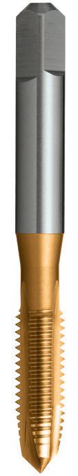
Catalogue Code T395
Discount Group D0706
Material HSSE
Surface Finish TiN Sutton Designation N
73 73 0250 M 2.5 x 0.45 45 10 - 2.80 2.24 5 3 2.05 • 0300 M 3 x 0.5 48 11 15 3.15 2.50 5 3 2.5 T395 0300 0350 M 3.5 x 0.6 50 13 17.5 3.55 2.80 5 3 2.9 T395 0350 0400 M 4 x 0.7 53 13 18 4.00 3.15 6 3 3.3 T395 0400 0500 M 5 x 0.8 58 16 22 5.00 4.00 7 3 4.2 T395 0500 0600 M 6 x 1 66 19 26 6.30 5.00 8 3 5.0 T395 0600 0800 M 8 x 1.25 72 22 30 8.00 6.30 9 3 6.8 T395 0800 1000 M 10 x 1.5 80 24 34 10.00 8.00 11 3 8.5 T395 1000 1200 M 12 x 1.75 89 29 - 9.00 7.10 10 3 10.2 T395 1200 1400 M 14 x 2 95 30 - 11.20 9.00 12 3 12.0 • 1600 M 16 x 2 102 32 - 12.50 10.00 13 3 14.0 T395 1600 1800 M 18 x 2.5 112 37 - 14.00 11.20 14 4 15.5 T395 1800 2000 M 20 x 2.5 112 37 - 14.00 11.20 14 4 17.5 T395 2000 2200 M 22* x 2.5 118 38 - 16.00 12.50 16 4 19.5 • 2400 M 24* x 3 130 45 - 18.00 14.00 18 4 21.0 • 3000 M 30* x 3.5 138 48 - 20.00 16.00 20 4 26.5 • P Steel M Stainless Steel K Cast Iron N Non-Ferrous Metals S Titanium & Super Alloys H Hard Materials T395 VDI 3323 ISO • 1 P • 2 • 3 • 4 • 5 • 6 • 7 • 8 9 • 10 11 • 12 • 13 • 14.1 M • 14.2 14.3 15 K 16 • 17 • 18 • 19 20 • 21 N • 22 • 23 • 24 • 25 • 26 • 27 28 29 30 31 S 32 33 34 35 36 37.1 37.2 37.3 37.4 37.5 • Optimal • Effective 38.1 H 38.2 39.1 39.2 • 40 41 *HSS >20mm • Available on request as special manufacture. Subject to lead time.
General purpose use
Suitable for materials up to 1000N/mm2
Through holes
3 x d1
Gun, N
-
-
-
- Depths up to approx.
ISO Taps Metric,
GeometryChamfer Intermediate Limit & Nut Tolerance ISO 2 / 6H Size Ref. d1 Pitch l1 l2 l3 d2 sq l4 z drill ø Item # M Contents Index
- General purpose use
- Suitable for materials up to 1000N/mm2
- Blind holes
- Depths up to approx. 2.5 x d1
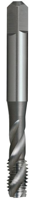
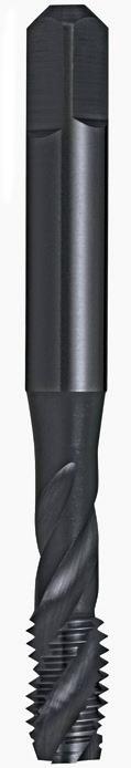
74 74 74 P Steel M Stainless Steel K Cast Iron N Non-Ferrous Metals S Titanium & Super Alloys H Hard Materials T396 T397 VDI 3323 ISO • • 1 P • • 2 • • 3 • • 4 5 • • 6 • 7 8 9 10 11 • 12 13 • • 14.1 M • • 14.2 14.3 15 K 16 • • 17 • • 18 19 20 • 21 N • 22 • 23 • 24 25 • 26 • 27 • 28 29 30 31 S 32 33 34 35 36 37.1 37.2 37.3 37.4 37.5 • Optimal • Effective 38.1 H 38.2 39.1 39.2 • • 40 41 0250 M 2.5 x 0.45 45 5 - 2.80 2.24 5 2 2.05 T397 0250 • 0300 M 3 x 0.5 48 6 15 3.15 2.50 5 3 2.5 T397 0300 T396 0300 0350 M 3.5 x 0.6 50 6 17.5 3.55 2.80 5 3 2.9 T397 0350 T396 0350 0400 M 4 x 0.7 53 7 18 4.00 3.15 6 3 3.3 T397 0400 T396 0400 0500 M 5 x 0.8 58 8 22 5.00 4.00 7 3 4.2 T397 0500 T396 0500 0600 M 6 x 1 66 10 26 6.30 5.00 8 3 5.0 T397 0600 T396 0600 0800 M 8 x 1.25 72 13 30 8.00 6.30 9 3 6.8 T397 0800 T396 0800 1000 M 10 x 1.5 80 15 34 10.00 8.00 11 3 8.5 T397 1000 T396 1000 1200 M 12 x 1.75 89 18 - 9.00 7.10 10 3 10.2 T397 1200 T396 1200 1400 M 14 x 2 95 20 - 11.20 9.00 12 3 12.0 T397 1400 T396 1400 1600 M 16 x 2 102 20 - 12.50 10.00 13 3 14.0 T397 1600 T396 1600 1800 M 18 x 2.5 112 25 - 14.00 11.20 14 4 15.5 T397 1800 T396 1800 2000 M 20 x 2.5 112 25 - 14.00 11.20 14 4 17.5 T397 2000 T396 2000 2200 M 22* x 2.5 118 38 - 16.00 12.50 16 4 19.5 T397 2200 T396 2200 2400 M 24* x 3 130 45 - 18.00 14.00 18 4 21.0 T397 2400 T396 2400 3000 M 30* x 3.5 138 48 - 20.00 16.00 20 4 26.5 T397 3000 T396 3000 *HSS >20mm • Available on request as special manufacture. Subject to lead time.
Catalogue Code T397 T396 Discount Group D0702 D0702 Material HSSE HSSE Surface Finish Brt Blu Sutton Designation N N Geometry R40 R40 Chamfer Bottoming Bottoming Limit & Nut Tolerance ISO 2 / 6H ISO 2 / 6H Size Ref. d1 Pitch l1 l2 l3 d2 sq l4 z drill ø Item # Item # ISO Taps Metric, Spiral Flute, N M Contents Index
ISO Taps Metric, Spiral Flute,

75 75 0250 M 2.5 x 0.45 45 5 - 2.80 2.24 5 2 2.05 • 0300 M 3 x 0.5 48 6 15 3.15 2.50 5 3 2.5 T398 0300 0350 M 3.5 x 0.6 50 6 17.5 3.55 2.80 5 3 2.9 • 0400 M 4 x 0.7 53 7 18 4.00 3.15 6 3 3.3 T398 0400 0500 M 5 x 0.8 58 8 22 5.00 4.00 7 3 4.2 T398 0500 0600 M 6 x 1 66 10 26 6.30 5.00 8 3 5.0 T398 0600 0800 M 8 x 1.25 72 13 30 8.00 6.30 9 3 6.8 T398 0800 1000 M 10 x 1.5 80 15 34 10.00 8.00 11 3 8.5 T398 1000 1200 M 12 x 1.75 89 18 - 9.00 7.10 10 3 10.2 T398 1200 1400 M 14 x 2 95 20 - 11.20 9.00 12 3 12.0 • 1600 M 16 x 2 102 20 - 12.50 10.00 13 3 14.0 T398 1600 1800 M 18 x 2.5 112 25 - 14.00 11.20 14 4 15.5 T398 1800 2000 M 20 x 2.5 112 25 - 14.00 11.20 14 4 17.5 T398 2000 2200 M 22* x 2.5 118 38 - 16.00 12.50 16 4 19.5 • 2400 M 24* x 3 130 45 - 18.00 14.00 18 4 21.0 • 3000 M 30* x 3.5 138 48 - 20.00 16.00 20 4 26.5 • P Steel M Stainless Steel K Cast Iron N Non-Ferrous Metals S Titanium & Super Alloys H Hard Materials T398 VDI 3323 ISO • 1 P • 2 • 3 • 4 • 5 • 6 • 7 • 8 9 • 10 11 • 12 • 13 • 14.1 M • 14.2 14.3 15 K 16 • 17 • 18 19 20 • 21 N • 22 • 23 • 24 • 25 26 • 27 28 29 30 31 S 32 33 34 35 36 37.1 37.2 37.3 37.4 37.5 • Optimal • Effective 38.1 H 38.2 39.1 39.2 • 40 41 *HSS >20mm • Available on request as special manufacture. Subject to lead time. - General purpose use - Suitable for materials up to 1000N/mm2 - Blind holes - Depths up to approx. 2.5 x d1 Catalogue Code T398 Discount Group D0706 Material HSSE Surface Finish TiN Sutton Designation N Geometry R40 Chamfer Bottoming Limit & Nut Tolerance ISO 2 / 6H Size Ref. d1 Pitch l1 l2 l3 d2 sq l4 z drill ø Item #
N M Contents Index
ISO Taps Metric, Forming, Single Coolant Groove
- For cold forming of threads in materials with good flow characteristics
- Through or blind holes
- Depths up to approx. 1.5 x d1
- TiN for longer tool life
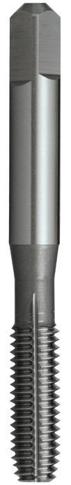
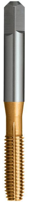
76 76 76 P Steel M Stainless Steel K Cast Iron N Non-Ferrous Metals S Titanium & Super Alloys H Hard Materials T400 T399 VDI 3323 ISO • • 1 P • • 2 • • 3 • • 4 5 • • 6 • 7 8 9 10 11 12 13 • 14.1 M 14.2 14.3 15 K 16 17 18 19 20 • • 21 N • • 22 • • 23 • • 24 25 • • 26 27 • • 28 29 30 31 S 32 33 34 35 36 37.1 37.2 37.3 37.4 37.5 • Optimal • Effective 38.1 H 38.2 39.1 39.2 40 41 0250 M 2.5 x 0.45 45 10 - 2.80 2.24 5 - 2.3 T399 0250 • 0300 M 3 x 0.5 48 11 15 3.15 2.50 5 - 2.8 T399 0300 T400 0300 0350 M 3.5 x 0.6 50 13 17.5 3.55 2.80 5 - 3.2 T399 0350 • 0400 M 4 x 0.7 53 13 18 4.00 3.15 6 - 3.7 T399 0400 T400 0400 0500 M 5 x 0.8 58 16 22 5.00 4.00 7 - 4.6 T399 0500 T400 0500 0600 M 6 x 1 66 19 26 6.30 5.00 8 - 5.5 T399 0600 T400 0600 0800 M 8 x 1.25 72 22 30 8.00 6.30 9 - 7.4 T399 0800 • 1000 M 10 x 1.5 80 24 34 10.00 8.00 11 - 9.3 T399 1000 • 1200 M 12 x 1.75 89 29 - 9.00 7.10 10 - 11.2 T399 1200 • T637 1005 MF 10 x 1 80 24 34 10.00 8.00 11 - 9.5 T637 1005 • 1206 MF 12 x 1.25 89 29 - 9.00 7.00 10 - 11.4 T637 1206 • • Available on request as special manufacture. Subject to lead time.
Catalogue Code T399 T400 Discount Group D0702 D0706 Material HSSE HSSE Surface Finish Brt TiN Sutton Designation N N Geometry Single Coolant Groove ≥ M3 Single Coolant Groove ≥ M3 Chamfer Short Short Limit & Nut Tolerance GH4 / 6H GH4 / 6H Size Ref. d1 Pitch l1 l2 l3 d2 sq l4 z drill ø Item # Item # M Contents Index
ISO Taps Metric Fine, Straight Flute, N
-
- Suitable for materials up to 1000N/mm2
- Through & blind holes
-
77 77 P Steel M Stainless Steel K Cast Iron N Non-Ferrous Metals S Titanium & Super Alloys H Hard Materials T402 T401 VDI 3323 ISO • • 1 P • • 2 • • 3 • • 4 5 • • 6 • • 7 8 9 10 11 12 13 14.1 M 14.2 14.3 • • 15 K 16 • • 17 18 • • 19 20 • • 21 N • • 22 • • 23 • • 24 25 • • 26 27 • • 28 29 30 31 S 32 33 34 35 36 37.1 37.2 37.3 37.4 37.5 • Optimal • Effective 38.1 H 38.2 39.1 39.2 40 41 0503 MF 5 x 0.5 58 16 22 5.0 4.0 7 4 4.5 • • 0604 MF 6 x 0.75 66 19 26 6.3 5.0 8 4 5.3 • • 0805 MF 8 x 1* 72 22 30 8.0 6.3 9 4 7.0 T401 0805 T402 0805 0804 MF 8 x 0.75 72 22 30 8.0 6.3 9 4 7.3 • • 1004 MF 10 x 0.75 80 24 34 10.0 8.0 11 4 9.3 • • 1005 MF 10 x 1† 80 24 34 10.0 8.0 11 4 9.0 T401 1005 T402 1005 1006 MF 10 x 1.25* 80 24 34 10.0 8.0 11 4 8.8 T401 1006 T402 1006 1205 MF 12 x 1 89 29 - 9.0 7.1 10 4 11.0 T401 1205 T402 1205 1206 MF 12 x 1.25 89 29 - 9.0 7.1 10 4 10.8 T401 1206 T402 1206 1207 MF 12 x 1.5* 89 29 - 9.0 7.1 10 4 10.5 T401 1207 T402 1207 1405 MF 14 x 1 95 30 - 11.2 9.0 12 4 13.0 • • 1406 MF14 x 1.25† 95 30 - 11.2 9.0 12 4 12.8 T401 1406 T402 1406 1407 MF 14 x 1.5* 95 30 - 11.2 9.0 12 4 12.5 T401 1407 T402 1407 1605 MF 16 x 1 102 32 - 12.5 10.0 13 4 15.0 • • 1606 MF 16 x 1.25 102 32 - 12.5 10.0 13 4 14.8 • • 1607 MF 16 x 1.5* 102 32 - 12.5 10.0 13 4 14.5 T401 1607 T402 1607 1806 MF 18 x 1.25 112 37 - 14.0 11.2 14 4 16.8 • • 1807 MF 18 x 1.5* 112 37 - 14.0 11.2 14 4 16.5 T401 1807 T402 1807 2006 MF 20 x 1.25 112 37 - 14.0 11.2 14 4 18.8 • • 2007 MF 20 x 1.5** 112 37 - 14.0 11.2 14 4 18.5 T401 2007 T402 2007 2008 MF 20 x 2* 112 37 - 14.0 11.2 14 4 18.0 • • 2207 MF 22 x 1.5 118 38 - 16.0 12.5 16 4 20.5 T401 2207 T402 2207 2208 MF 22 x 2 118 38 - 16.0 12.5 16 4 20.0 • • 2407 MF 24 x 1.5 130 45 - 18.0 14.0 18 4 22.5 • • 2408 MF 24 x 2* 130 45 - 18.0 14.0 18 4 22.0 T401 2408 T402 2408 2507 MF 25 x 1.5** 130 45 - 18.0 14.0 18 4 23.5 T401 2507 T402 2507 2708 MF 27 x 2 135 45 - 20.0 16.0 20 4 25.0 • • 3007 MF 30 x 1.5 138 48 - 20.0 16.0 20 4 28.5 T401 3007 T402 3007 3008 MF 30 x 2 138 48 - 20.0 16.0 20 4 28.0 T401 3008 T402 3008 3207 MF 32 x 1.5** 151 51 - 22.4 18.0 22 4 30.5 T401 3207 T402 3207 4007 MF 40 x 1.5** 170 60 - 28.0 22.4 26 4 38.5 T401 4007 T402 4007 1005 MF 10 x 1† 80 24 34 10.0 8.0 11 4 9.0 T401 1005 T402 1005 1206 MF 12 x 1.25 89 29 - 9.0 7.1 10 4 10.8 T401 1206 T402 1206 1406 MF 14 x 1.25† 95 30 - 11.2 9.0 12 4 12.8 T401 1406 T402 1406 1807 MF 18 x 1.5 112 37 - 14.0 11.2 14 4 16.5 T401 1807 T402 1807 * Alternative Metric Fine ** Conduit Metric • Available on request as special manufacture. Subject to lead time. † Limit & Nut Tolerance: ISO 1 / 4H
General purpose use
Suitable
both hand
machine
Depths up to approx. 1
d1 Catalogue Code T401 T402 Discount Group D0702 D0702 Material HSS HSS Surface Finish Brt Brt Sutton Designation N N Geometry -Chamfer Taper Intermediate Limit & Nut Tolerance ISO 2 / 6H ISO 2 / 6H Size Ref. d1 Pitch l1 l2 l3 d2 sq l4 z drill ø Item # Item #
for
and
operations -
x
Spark
MF Contents Index
Plug
ISO Taps Metric Fine, Straight Flute, N
- General purpose use
- Suitable for materials up to 1000N/mm2
- Through & blind holes
-
- Suitable for both hand and machine operations
up to approx. 1 x
78 P Steel M Stainless Steel K Cast Iron N Non-Ferrous Metals S Titanium & Super Alloys H Hard Materials T902 T403 VDI 3323 ISO • • 1 P • • 2 • • 3 • • 4 5 • • 6 • • 7 8 9 10 11 12 13 14.1 M 14.2 14.3 • • 15 K 16 • • 17 18 • • 19 20 • • 21 N • • 22 • • 23 • • 24 25 • • 26 27 • • 28 29 30 31 S 32 33 34 35 36 37.1 37.2 37.3 37.4 37.5 • Optimal • Effective 38.1 H 38.2 39.1 39.2 40 41 0503 MF 5 x 0.5 58 16 22 5.0 4.0 7 4 4.5 T403 0503 • 0604 MF 6 x 0.75 66 19 26 6.3 5.0 8 4 5.3 T403 0604 • 0805 MF 8 x 1* 72 22 30 8.0 6.3 9 4 7.0 T403 0805 T902 0805 0804 MF 8 x 0.75 72 22 30 8.0 6.3 9 4 7.3 T403 0804 • 1004 MF 10 x 0.75 80 24 34 10.0 8.0 11 4 9.3 T403 1004 • 1005 MF 10 x 1† 80 24 34 10.0 8.0 11 4 9.0 T403 1005 T902 1005 1006 MF 10 x 1.25* 80 24 34 10.0 8.0 11 4 8.8 T403 1006 T902 1006 1205 MF 12 x 1 89 29 - 9.0 7.1 10 4 11.0 T403 1205 • 1206 MF 12 x 1.25 89 29 - 9.0 7.1 10 4 10.8 T403 1206 T902 1206 1207 MF 12 x 1.5* 89 29 - 9.0 7.1 10 4 10.5 T403 1207 T902 1207 1405 MF 14 x 1 95 30 - 11.2 9.0 12 4 13.0 T403 1405 • 1406 MF14 x 1.25† 95 30 - 11.2 9.0 12 4 12.8 T403 1406 T902 1406 1407 MF 14 x 1.5* 95 30 - 11.2 9.0 12 4 12.5 T403 1407 T902 1407 1605 MF 16 x 1 102 32 - 12.5 10.0 13 4 15.0 T403 1605 • 1606 MF 16 x 1.25 102 32 - 12.5 10.0 13 4 14.8 T403 1606 • 1607 MF 16 x 1.5* 102 32 - 12.5 10.0 13 4 14.5 T403 1607 T902 1607 1806 MF 18 x 1.25 112 37 - 14.0 11.2 14 4 16.8 T403 1806 • 1807 MF 18 x 1.5* 112 37 - 14.0 11.2 14 4 16.5 T403 1807 T902 1807 2006 MF 20 x 1.25 112 37 - 14.0 11.2 14 4 18.8 T403 2006 • 2007 MF 20 x 1.5** 112 37 - 14.0 11.2 14 4 18.5 T403 2007 T902 2007 2008 MF 20 x 2* 112 37 - 14.0 11.2 14 4 18.0 T403 2008 • 2207 MF 22 x 1.5 118 38 - 16.0 12.5 16 4 20.5 T403 2207 T902 2207 2208 MF 22 x 2 118 38 - 16.0 12.5 16 4 20.0 T403 2208 • 2407 MF 24 x 1.5 130 45 - 18.0 14.0 18 4 22.5 T403 2407 • 2408 MF 24 x 2* 130 45 - 18.0 14.0 18 4 22.0 T403 2408 T902 2408 2507 MF 25 x 1.5** 130 45 - 18.0 14.0 18 4 23.5 T403 2507 • 2708 MF 27 x 2 135 45 - 20.0 16.0 20 4 25.0 T403 2708 • 3007 MF 30 x 1.5 138 48 - 20.0 16.0 20 4 28.5 T403 3007 • 3008 MF 30 x 2 138 48 - 20.0 16.0 20 4 28.0 T403 3008 • 3207 MF 32 x 1.5** 151 51 - 22.4 18.0 22 4 30.5 T403 3207 • 4007 MF 40 x 1.5** 170 60 - 28.0 22.4 26 4 38.5 T403 4007 • 1005 MF 10 x 1† 80 24 34 10.0 8.0 11 4 9.0 T403 1005 T902 1005 1206 MF 12 x 1.25 89 29 - 9.0 7.1 10 4 10.8 T403 1206 T902 1206 1406 MF 14 x 1.25† 95 30 - 11.2 9.0 12 4 12.8 T403 1406 T902 1406 1807 MF 18 x 1.5 112 37 - 14.0 11.2 14 4 16.5 T403 1807 T902 1807 * Alternative Metric Fine ** Conduit Metric • Available on request as special manufacture. Subject to lead time. † Limit & Nut Tolerance: ISO 1 / 4H
Depths
Catalogue Code T403 T902 Discount Group D0702 D0702 Material HSS HSS Surface Finish Brt Brt Sutton Designation N N Geometry -Chamfer Bottoming Set Limit & Nut Tolerance ISO 2 / 6H ISO 2 / 6H Size Ref. d1 Pitch l1 l2 l3 d2 sq l4 z drill ø Item # Item #
d1
Spark Plug MF Contents Index
ISO Taps Metric Fine, Gun, N
- General purpose use
- Suitable for materials up to 1000N/mm2
- Through holes
- Depths up to approx. 3 x d1
79 79 79 P Steel M Stainless Steel K Cast Iron N Non-Ferrous Metals S Titanium & Super Alloys H Hard Materials T407 T406 VDI 3323 ISO • • 1 P • • 2 • • 3 • • 4 5 • • 6 • • 7 8 9 10 11 • 12 13 • • 14.1 M • • 14.2 14.3 15 K 16 • • 17 • • 18 • • 19 20 • 21 N • 22 • 23 • 24 25 • 26 • 27 28 29 30 31 S 32 33 34 35 36 37.1 37.2 37.3 37.4 37.5 • Optimal • Effective 38.1 H 38.2 39.1 39.2 • • 40 41 0503 MF 5 x 0.5 58 16 22 5.0 4.0 7 3 4.5 • T407 0503 0604 MF 6 x 0.75 66 19 26 6.3 5.0 8 3 5.3 • T407 0604 0805 MF 8 x 1 72 22 30 8.0 6.3 9 3 7.0 T406 0805 T407 0805 1005 MF 10 x 1 80 24 34 10.0 8.0 11 3 9.0 • T407 1005 1006 MF 10 x 1.25 80 24 34 10.0 8.0 11 3 8.8 T406 1006 T407 1006 1206 MF 12 x 1.25 89 29 - 9.0 7.1 10 3 10.8 • T407 1206 1207 MF 12 x 1.5 89 29 - 9.0 7.1 10 3 10.5 T406 1207 T407 1207 1407 MF 14 x 1.5 95 30 - 11.2 9.0 12 3 12.5 • T407 1407 1607 MF 16 x 1.5 102 32 - 12.5 10.0 13 3 14.5 • T407 1607 1807 MF 18 x 1.5 112 37 - 14.0 11.2 14 4 16.5 • T407 1807 2007 MF 20 x 1.5 112 37 - 14.0 11.2 14 4 18.5 • T407 2007 2207 MF 22 x 1.5 118 38 - 16.0 12.5 16 4 20.5 • T407 2207 • Available on request as special manufacture. Subject to lead time.
Catalogue Code T406 T407 Discount Group D0702 D0702 Material HSSE HSSE Surface Finish Brt Blu Sutton Designation N N Geometry -Chamfer Intermediate Intermediate Limit & Nut Tolerance ISO 2 / 6H ISO 2 / 6H Size Ref. d1 Pitch l1 l2 l3 d2 sq l4 z drill ø Item # Item #
MF Contents Index
- General purpose use
- Suitable for materials up to 1000N/mm2
- Through holes
- Depths up to approx. 3 x d1
Catalogue Code T408
Discount Group D0706
Material HSSE
Surface Finish TiN
Sutton Designation N
GeometryChamfer
Tolerance
80 80 0503 MF 5 x 0.5 58 16 22 5.0 4.0 7 3 4.5 • 0604 MF 6 x 0.75 66 19 26 6.3 5.0 8 3 5.3 • 0805 MF 8 x 1 72 22 30 8.0 6.3 9 3 7.0 T408 0805 1005 MF 10 x 1 80 24 34 10.0 8.0 11 3 9.0 • 1006 MF 10 x 1.25 80 24 34 10.0 8.0 11 3 8.8 T408 1006 1206 MF 12 x 1.25 89 29 - 9.0 7.1 10 3 10.8 • 1207 MF 12 x 1.5 89 29 - 9.0 7.1 10 3 10.5 T408 1207 1407 MF 14 x 1.5 95 30 - 11.2 9.0 12 3 12.5 • 1607 MF 16 x 1.5 102 32 - 12.5 10.0 13 3 14.5 • 1807 MF 18 x 1.5 112 37 - 14.0 11.2 14 4 16.5 • 2007 MF 20 x 1.5 112 37 - 14.0 11.2 14 4 18.5 • 2207 MF 22 x 1.5 118 38 - 16.0 12.5 16 4 20.5 • P Steel M Stainless Steel K Cast Iron N Non-Ferrous Metals S Titanium & Super Alloys H Hard Materials T408 VDI 3323 ISO • 1 P • 2 • 3 • 4 • 5 • 6 • 7 • 8 9 • 10 11 • 12 • 13 • 14.1 M • 14.2 14.3 15 K 16 • 17 • 18 • 19 20 • 21 N • 22 • 23 • 24 • 25 • 26 • 27 28 29 30 31 S 32 33 34 35 36 37.1 37.2 37.3 37.4 37.5 • Optimal • Effective 38.1 H 38.2 39.1 39.2 • 40 41 • Available on request as special manufacture. Subject to lead time.
Intermediate Limit & Nut
ISO 2 / 6H Size Ref. d1 Pitch l1 l2 l3 d2 sq l4 z drill ø Item #
N MF Contents Index
ISO Taps Metric Fine, Gun,
ISO Taps Metric Fine, Spiral Flute, N
- General purpose use
- Suitable for materials up to 1000N/mm2
- Blind holes
- Depths up to approx. 2.5 x d1
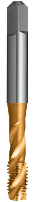
81 81 81 P Steel M Stainless Steel K Cast Iron N Non-Ferrous Metals S Titanium & Super Alloys H Hard Materials T411 T409 VDI 3323 ISO • • 1 P • • 2 • • 3 • • 4 • 5 • • 6 • 7 • 8 9 • 10 11 • 12 • 13 • • 14.1 M • • 14.2 14.3 15 K 16 • • 17 • • 18 19 20 • • 21 N • • 22 • • 23 • • 24 • 25 • 26 • • 27 • 28 29 30 31 S 32 33 34 35 36 37.1 37.2 37.3 37.4 37.5 • Optimal • Effective 38.1 H 38.2 39.1 39.2 • • 40 41 0503 MF 5 x 0.5 58 16 22 5.0 4.0 7 3 4.5 T409 0503 • 0604 MF 6 x 0.75 66 19 26 6.3 5.0 8 3 5.3 T409 0604 • 0805 MF 8 x 1 72 22 30 8.0 6.3 9 3 7.0 T409 0805 T411 0805 1005 MF 10 x 1 80 24 34 10.0 8.0 11 3 9.0 T409 1005 • 1006 MF 10 x 1.25 80 24 34 10.0 8.0 11 3 8.8 T409 1006 T411 1006 1206 MF 12 x 1.25 89 29 - 9.0 7.1 10 3 10.8 T409 1206 • 1207 MF 12 x 1.5 89 29 - 9.0 7.1 10 3 10.5 T409 1207 T411 1207 1406 MF 14 x 1.25 95 30 - 11.2 9.0 12 3 12.8 T409 1406 • 1407 MF 14 x 1.5 95 30 - 11.2 9.0 12 3 12.5 T409 1407 • 1607 MF 16 x 1.5 102 32 - 12.5 10.0 13 3 14.5 T409 1607 • 1807 MF 18 x 1.5 112 37 - 14.0 11.2 14 4 16.5 T409 1807 • 2007 MF 20 x 1.5 112 37 - 14.0 11.2 14 4 18.5 T409 2007 • 2207 MF 22 x 1.5 118 38 - 16.0 12.5 16 4 20.5 T409 2207 • • Available on request as special manufacture. Subject to lead time.
Catalogue Code T409 T411 Discount Group D0702 D0706 Material HSSE HSSE Surface Finish Brt TiN Sutton Designation N N Geometry R40 R40 Chamfer Bottoming Bottoming Limit & Nut Tolerance ISO 2 / 6H ISO 2 / 6H Size Ref. d1 Pitch l1 l2 l3 d2 sq l4 z drill ø Item # Item # MF Contents Index
- General purpose use
- Suitable for materials
- Through & blind holes
- Suitable for both hand
-
82 82 P Steel M Stainless Steel K Cast Iron N Non-Ferrous Metals S Titanium & Super Alloys H Hard Materials T415 T414 VDI 3323 ISO • • 1 P • • 2 • • 3 • • 4 5 • • 6 • • 7 8 9 10 11 12 13 14.1 M 14.2 14.3 • • 15 K 16 • • 17 18 • • 19 20 • • 21 N • • 22 • • 23 • • 24 25 • • 26 27 • • 28 29 30 31 S 32 33 34 35 36 37.1 37.2 37.3 37.4 37.5 • Optimal • Effective 38.1 H 38.2 39.1 39.2 40 41 0251 #3 48 45 10 - 2.80 2.24 5 3 GH2 T414 0251 T415 0251 0284 #4 40 48 15 14.5 3.15 2.50 5 3 GH2 T414 0284 T415 0284 0318 #5 40 48 15 15 3.15 2.50 5 3 GH2 T414 0318 T415 0318 0351 #6 32 50 17 17.5 3.55 2.80 5 3 GH3 T414 0351 T415 0351 0417 #8 32 53 13 17 4.50 3.55 6 3 GH3 T414 0417 T415 0417 0476 3/16 24 (UNS) 58 16 22 5.00 4.00 7 3 GH4 T414 0476 T415 0476 0483 #10 24 58 16 22 5.00 4.00 7 3 GH4 T414 0483 T415 0483 0549 #12 24 62 17 23 5.60 4.50 7 3 GH4 T414 0549 T415 0549 0635 1/4 20 66 19 25 6.30 5.00 8 3 GH4 T414 0635 T415 0635 0636 1/4^ 20 66 19 25 6.30 5.00 8 3 GH3 • • 0794 5/16^ 18 72 22 30 8.00 6.30 9 4 GH5 T414 0794 T415 0794 0953 3/8 16 80 24 33 10.00 8.00 11 4 GH5 T414 0953 T415 0953 1111 7/16 14 85 25 - 8.00 6.30 9 4 GH3 T414 1111 T415 1111 1270 1/2 13 89 29 - 9.00 7.10 10 4 GH6 T414 1270 T415 1270 1429 9/16 12 95 30 - 11.20 9.00 12 4 GH6 T414 1429 T415 1429 1588 5/8 11 102 32 - 12.50 10.00 13 4 GH6 T414 1588 T415 1588 1905 3/4 10 112 37 - 14.00 11.20 14 4 GH7 T414 1905 T415 1905 2223 7/8 9 118 38 - 16.00 12.50 16 4 GH7 T414 2223 T415 2223 2540 1 8 130 45 - 18.00 14.00 18 4 GH7 T414 2540 T415 2540 2858 1-1/8 7 138 48 - 20.00 16.00 20 4 GH8 T414 2858 T415 2858 3175 1-1/4 7 151 51 - 22.40 18.00 22 4 GH8 T414 3175 T415 3175 3810 1-1/2 6 170 60 - 28.00 22.40 26 4 GH8 T414 3810 T415 3810 ^ Alternative Limit • Available on request as special manufacture. Subject to lead time.
up
1000N/mm2
to
machine
and
operations
Depths up
d1 Catalogue Code T414 T415 Discount Group D0702 D0702 Material HSS HSS Surface Finish Brt Brt Sutton Designation N N Geometry -Chamfer Taper Intermediate Limit & Nut Tolerance 2B 2B Size Ref. d1 TPI l1 l2 l3 d2 sq l4 z Limit Item # Item # ISO Taps UNC, Straight Flute, N UNC Contents Index
to approx. 1 x
-
83 0251 #3 48 45 10 - 2.80 2.24 5 3 GH2 T416 0251 • 0284 #4 40 48 15 14.5 3.15 2.50 5 3 GH2 T416 0284 T903 0284 0318 #5 40 48 15 15 3.15 2.50 5 3 GH2 T416 0318 T903 0318 0351 #6 32 50 17 17.5 3.55 2.80 5 3 GH3 T416 0351 T903 0351 0417 #8 32 53 13 17 4.50 3.55 6 3 GH3 T416 0417 T903 0417 0476 3/16 24 (UNS) 58 16 22 5.00 4.00 7 3 GH4 T416 0476 T903 0476 0483 #10 24 58 16 22 5.00 4.00 7 3 GH4 T416 0483 T903 0483 0549 #12 24 62 17 23 5.60 4.50 7 3 GH4 T416 0549 T903 0549 0635 1/4 20 66 19 25 6.30 5.00 8 3 GH4 T416 0635 T903 0635 0636 1/4^ 20 66 19 25 6.30 5.00 8 3 GH3 T416 0636 • 0794 5/16^ 18 72 22 30 8.00 6.30 9 4 GH5 T416 0794 T903 0794 0795 5/16 18 72 22 30 8.00 6.30 9 4 GH3 T416 0795 • 0953 3/8 16 80 24 33 10.00 8.00 11 4 GH5 T416 0953 T903 0953 1111 7/16 14 85 25 - 8.00 6.30 9 4 GH3 T416 1111 T903 1111 1270 1/2 13 89 29 - 9.00 7.10 10 4 GH6 T416 1270 T903 1270 1429 9/16 12 95 30 - 11.20 9.00 12 4 GH6 T416 1429 T903 1429 1588 5/8 11 102 32 - 12.50 10.00 13 4 GH6 T416 1588 T903 1588 1905 3/4 10 112 37 - 14.00 11.20 14 4 GH7 T416 1905 T903 1905 2223 7/8 9 118 38 - 16.00 12.50 16 4 GH7 T416 2223 T903 2223 2540 1 8 130 45 - 18.00 14.00 18 4 GH7 T416 2540 T903 2540 2858 1-1/8 7 138 48 - 20.00 16.00 20 4 GH8 T416 2858 • 3175 1-1/4 7 151 51 - 22.40 18.00 22 4 GH8 T416 3175 T903 3175 3810 1-1/2 6 170 60 - 28.00 22.40 26 4 GH8 T416 3810 T903 3810 P Steel M Stainless Steel K Cast Iron N Non-Ferrous Metals S Titanium & Super Alloys H Hard Materials T903 T416 VDI 3323 ISO • • 1 P • • 2 • • 3 • • 4 5 • • 6 • • 7 8 9 10 11 12 13 14.1 M 14.2 14.3 • • 15 K 16 • • 17 18 • • 19 20 • • 21 N • • 22 • • 23 • • 24 25 • • 26 27 • • 28 29 30 31 S 32 33 34 35 36 37.1 37.2 37.3 37.4 37.5 • Optimal • Effective 38.1 H 38.2 39.1 39.2 40 41 ^ Alternative Limit • Available on request as special manufacture. Subject to lead time. - General purpose use
Suitable for materials up to 1000N/mm2
Through & blind holes
Suitable for both hand and machine operations
Depths up to approx. 1 x d1 Catalogue Code T416 T903 Discount Group D0702 D0702 Material HSS HSS Surface Finish Brt Brt Sutton Designation N N Geometry -Chamfer Bottoming Set Limit & Nut Tolerance 2B 2B Size Ref. d1 TPI l1 l2 l3 d2 sq l4 z Limit Item # Item #
Straight
N UNC Contents Index
-
-
-
ISO Taps UNC,
Flute,
ISO Taps UNC, Straight Flute, N, Left Hand
- General purpose use
- Suitable for materials up to 1000N/mm2
- Through & blind holes
- Suitable for both hand and machine operations
- Depths up to approx. 1 x d1
84 84 P Steel M Stainless Steel K Cast Iron N Non-Ferrous Metals S Titanium & Super Alloys H Hard Materials T420 T419 VDI 3323 ISO • • 1 P • • 2 • • 3 • • 4 5 • • 6 • • 7 8 9 10 11 12 13 14.1 M 14.2 14.3 • • 15 K 16 • • 17 18 • • 19 20 • • 21 N • • 22 • • 23 • • 24 25 • • 26 27 • • 28 29 30 31 S 32 33 34 35 36 37.1 37.2 37.3 37.4 37.5 • Optimal • Effective 38.1 H 38.2 39.1 39.2 40 41 0635 1/4 20 66 19 25 6.30 5.00 8 3 GH4 5.1 T419 0635 T420 0635 0794 5/16 18 72 22 30 8.00 6.30 9 4 GH5 6.6 T419 0794 T420 0794 0953 3/8 16 80 24 33 10.00 8.00 11 4 GH5 8.0 T419 0953 T420 0953 1111 7/16 14 85 25 - 8.00 6.30 9 4 GH5 9.4 T419 1111 T420 1111 1270 1/2 13 89 29 - 9.00 7.10 10 4 GH6 10.8 T419 1270 T420 1270 1429 9/16 12 95 30 - 11.20 9.00 12 4 GH6 12.2 T419 1429 T420 1429 1588 5/8 11 102 32 - 12.50 10.00 13 4 GH6 13.5 T419 1588 T420 1588 1905 3/4 10 112 37 - 14.00 11.20 14 4 GH7 16.5 T419 1905 T420 1905 2223 7/8 9 118 38 - 16.00 12.50 16 4 GH7 19.5 • • 2540 1 8 130 45 - 18.00 14.00 18 4 GH7 22.2 • • 2858 1-1/8 7 138 48 - 20.00 16.00 20 4 GH8 25.0 • • 3175 1-1/4 7 151 51 - 22.40 18.00 22 4 GH8 28.0 • • 3810 1-1/2 6 170 60 - 28.00 22.40 26 4 GH8 34.0 • • • Available on request as special manufacture. Subject to lead time.
Catalogue Code T419 T420 Discount Group D0702 D0702 Material HSS HSS Surface Finish Brt Brt Sutton Designation N N Geometry Left Hand Left Hand Chamfer Taper Intermediate Nut Tolerance 2B LH 2B LH Size Ref. d1 TPI l1 l2 l3 d2 sq l4 z Limit drill ø Item # Item #
UNC Contents Index
-
ISO Taps UNC, Straight Flute, N, Left Hand
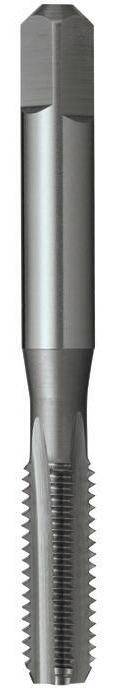
85 0635 1/4 20 66 19 25 6.30 5.00 8 3 GH4 5.1 T421 0635 0794 5/16 18 72 22 30 8.00 6.30 9 4 GH5 6.6 T421 0794 0953 3/8 16 80 24 33 10.00 8.00 11 4 GH5 8.0 T421 0953 1111 7/16 14 85 25 - 8.00 6.30 9 4 GH5 9.4 T421 1111 1270 1/2 13 89 29 - 9.00 7.10 10 4 GH6 10.8 T421 1270 1429 9/16 12 95 30 - 11.20 9.00 12 4 GH6 12.2 T421 1429 1588 5/8 11 102 32 - 12.50 10.00 13 4 GH6 13.5 T421 1588 1905 3/4 10 112 37 - 14.00 11.20 14 4 GH7 16.5 T421 1905 2223 7/8 9 118 38 - 16.00 12.50 16 4 GH7 19.5 • 2540 1 8 130 45 - 18.00 14.00 18 4 GH7 22.2 • 2858 1-1/8 7 138 48 - 20.00 16.00 20 4 GH8 25.0 • 3175 1-1/4 7 151 51 - 22.40 18.00 22 4 GH8 28.0 • 3810 1-1/2 6 170 60 - 28.00 22.40 26 4 GH8 34.0 • P Steel M Stainless Steel K Cast Iron N Non-Ferrous Metals S Titanium & Super Alloys H Hard Materials T421 VDI 3323 ISO • 1 P • 2 • 3 • 4 5 • 6 • 7 8 9 10 11 12 13 14.1 M 14.2 14.3 • 15 K 16 • 17 18 • 19 20 • 21 N • 22 • 23 • 24 25 • 26 27 • 28 29 30 31 S 32 33 34 35 36 37.1 37.2 37.3 37.4 37.5 • Optimal • Effective 38.1 H 38.2 39.1 39.2 40 41 • Available on request as special manufacture. Subject to lead time.
use
- General purpose
Suitable
materials up to 1000N/mm2
Through
blind holes
for
-
&
both hand and machine operations
approx. 1 x d1 Catalogue Code T421
Group D0702 Material
Chamfer Bottoming Nut
2B LH Size Ref. d1 TPI l1 l2 l3 d2 sq l4 z Limit drill ø Item #
- Suitable for
- Depths up to
Discount
HSS Surface Finish Brt Sutton Designation N Geometry Left Hand
Tolerance
UNC Contents Index
- General purpose use
- Suitable for materials up to 1000N/mm2
- Through holes
- Depths up to approx. 3 x d1
86 86 86 P Steel M Stainless Steel K Cast Iron N Non-Ferrous Metals S Titanium & Super Alloys H Hard Materials T423 T422 VDI 3323 ISO • • 1 P • • 2 • • 3 • • 4 5 • • 6 • • 7 8 9 10 11 • 12 13 • • 14.1 M • • 14.2 14.3 15 K 16 • • 17 • • 18 • • 19 20 • 21 N • 22 • 23 • 24 25 • 26 • 27 28 29 30 31 S 32 33 34 35 36 37.1 37.2 37.3 37.4 37.5 • Optimal • Effective 38.1 H 38.2 39.1 39.2 • • 40 41 0284 #4 40 48 15 14.5 3.15 2.50 5 2 GH2 2.3 T422 0284 T423 0284 0351 #6 32 50 17 17.5 3.55 2.80 5 3 GH3 2.8 T422 0351 T423 0351 0417 #8 32 53 13 18 4.50 3.55 6 3 GH3 3.4 T422 0417 T423 0417 0483 #10 24 58 16 22 5.00 4.00 7 3 GH4 3.8 T422 0483 T423 0483 0549 #12 24 62 17 23 5.60 4.50 7 3 GH4 4.5 • T423 0549 0635 1/4 20 66 19 25 6.30 5.00 8 3 GH4 5.1 T422 0635 T423 0635 0794 5/16 18 72 22 30 8.00 6.30 9 3 GH5 6.6 T422 0794 T423 0794 0953 3/8 16 80 24 33 10.00 8.00 11 3 GH5 8.0 T422 0953 T423 0953 1111 7/16 14 85 25 - 8.00 6.30 9 3 GH5 9.4 T422 1111 T423 1111 1270 1/2 13 89 29 - 9.00 7.10 10 3 GH6 10.8 T422 1270 T423 1270 1588 5/8 11 102 32 - 12.50 10.00 13 3 GH6 13.5 T422 1588 T423 1588 1905 3/4 10 112 37 - 14.00 11.20 14 4 GH7 16.5 T422 1905 T423 1905 2223 7/8 9 118 38 - 16.00 12.50 16 4 GH7 19.5 • T423 2223 2540 1 8 130 45 - 18.00 14.00 18 4 GH7 22.2 • T423 2540 • Available on request as special manufacture. Subject to lead time.
Catalogue Code T422 T423 Discount Group D0702 D0702 Material HSSE HSSE Surface Finish Brt Blu Sutton Designation N N Geometry -Chamfer Intermediate Intermediate Nut Tolerance 2B 2B Size Ref. d1 TPI l1 l2 l3 d2 sq l4 z Limit drill ø Item # Item # ISO Taps UNC, Gun, N UNC Contents Index
Catalogue Code T424
D0706
87 87 0284 #4 40 48 15 14.5 3.15 2.50 5 2 GH2 2.3 • 0351 #6 32 50 17 17.5 3.55 2.80 5 3 GH3 2.8 T424 0351 0417 #8 32 53 13 18 4.50 3.55 6 3 GH3 3.4 T424 0417 0483 #10 24 58 16 22 5.00 4.00 7 3 GH4 3.8 T424 0483 0549 #12 24 62 17 23 5.60 4.50 7 3 GH4 4.5 • 0635 1/4 20 66 19 25 6.30 5.00 8 3 GH4 5.1 T424 0635 0794 5/16 18 72 22 30 8.00 6.30 9 3 GH5 6.6 T424 0794 0953 3/8 16 80 24 33 10.00 8.00 11 3 GH5 8.0 T424 0953 1111 7/16 14 85 25 - 8.00 6.30 9 3 GH5 9.4 • 1270 1/2 13 89 29 - 9.00 7.10 10 3 GH6 10.8 T424 1270 1588 5/8 11 102 32 - 12.50 10.00 13 3 GH6 13.5 T424 1588 1905 3/4 10 112 37 - 14.00 11.20 14 4 GH7 16.5 T424 1905 2223 7/8 9 118 38 - 16.00 12.50 16 4 GH7 19.5 • 2540 1 8 130 45 - 18.00 14.00 18 4 GH7 22.2 • P Steel M Stainless Steel K Cast Iron N Non-Ferrous Metals S Titanium & Super Alloys H Hard Materials T424 VDI 3323 ISO • 1 P • 2 • 3 • 4 • 5 • 6 • 7 • 8 9 • 10 11 • 12 • 13 • 14.1 M • 14.2 14.3 15 K 16 • 17 • 18 • 19 20 • 21 N • 22 • 23 • 24 • 25 • 26 • 27 28 29 30 31 S 32 33 34 35 36 37.1 37.2 37.3 37.4 37.5 • Optimal • Effective 38.1 H 38.2 39.1 39.2 • 40 41 • Available on request as special manufacture. Subject to lead time. - General purpose use
Suitable for materials up to 1000N/mm2
Through holes
-
-
d1
- Depths up to approx. 3 x
GeometryChamfer Intermediate Nut Tolerance 2B Size Ref. d1 TPI l1 l2 l3 d2 sq l4 z Limit drill ø Item #
Gun, N UNC Contents Index
Discount Group
Material HSSE Surface Finish TiN Sutton Designation N
ISO Taps UNC,
- General purpose use
- Suitable for materials up to 1000N/mm2
- Blind holes
- Depths up to approx. 2.5 x d1
88 88 88 P Steel M Stainless Steel K Cast Iron N Non-Ferrous Metals S Titanium & Super Alloys H Hard Materials T426 T425 VDI 3323 ISO • • 1 P • • 2 • • 3 • • 4 5 • • 6 • 7 8 9 10 11 • 12 13 • • 14.1 M • • 14.2 14.3 15 K 16 • • 17 • • 18 19 20 • 21 N • 22 • 23 • 24 25 • 26 • 27 • 28 29 30 31 S 32 33 34 35 36 37.1 37.2 37.3 37.4 37.5 • Optimal • Effective 38.1 H 38.2 39.1 39.2 • • 40 41 0218 #2 56 41 8 - 2.5 2.0 - 2 GH2 1.85 T425 0218 • 0284 #4 40 48 6 - 3.15 2.50 5 3 GH2 2.3 T425 0284 • 0351 #6 32 50 6 - 3.55 2.80 5 3 GH3 2.8 T425 0351 • 0417 #8 32 53 8 18 4.50 3.55 6 3 GH3 3.4 T425 0417 • 0483 #10 24 58 11 22 5.00 4.00 7 3 GH4 3.8 T425 0483 • 0635 1/4 20 66 10 25 6.30 5.00 8 3 GH4 5.1 T425 0635 T426 0635 0794 5/16 18 72 13 30 8.00 6.30 9 3 GH5 6.6 T425 0794 T426 0794 0953 3/8 16 80 16 33 10.00 8.00 11 3 GH5 8.0 T425 0953 T426 0953 1111 7/16 14 85 18 - 8.00 6.30 9 3 GH5 9.4 T425 1111 T426 1111 1270 1/2 13 89 20 - 9.00 7.10 10 3 GH6 10.8 T425 1270 T426 1270 1588 5/8 11 102 20 - 12.50 10.00 13 3 GH6 13.5 T425 1588 T426 1588 1905 3/4 10 112 25 - 14.00 11.20 14 4 GH7 16.5 T425 1905 T426 1905 2223 7/8 9 118 38 - 16.00 12.50 16 4 GH7 19.5 T425 2223 • 2540 1 8 130 45 - 18.00 14.00 18 4 GH7 22.2 T425 2540 • • Available on request as special manufacture. Subject to lead time.
Catalogue Code T425 T426 Discount Group D0702 D0702 Material HSSE HSSE Surface Finish Brt Blu Sutton Designation N N Geometry R40 R40 Chamfer Bottoming Bottoming Nut Tolerance 2B 2B Size Ref. d1 TPI l1 l2 l3 d2 sq l4 z Limit drill ø Item # Item # ISO Taps UNC, Spiral Flute, N UNC Contents Index
89 89 0218 #2 56 41 8 - 2.5 2.0 - 2 GH2 1.85 • 0284 #4 40 48 6 - 3.15 2.50 5 3 GH2 2.3 • 0351 #6 32 50 6 - 3.55 2.80 5 3 GH3 2.8 • 0417 #8 32 53 8 18 4.50 3.55 6 3 GH3 3.4 • 0483 #10 24 58 11 22 5.00 4.00 7 3 GH4 3.8 T427 0483 0635 1/4 20 66 10 25 6.30 5.00 8 3 GH4 5.1 T427 0635 0794 5/16 18 72 13 30 8.00 6.30 9 3 GH5 6.6 T427 0794 0953 3/8 16 80 16 33 10.00 8.00 11 3 GH5 8.0 T427 0953 1111 7/16 14 85 18 - 8.00 6.30 9 3 GH5 9.4 T427 1111 1270 1/2 13 89 20 - 9.00 7.10 10 3 GH6 10.8 T427 1270 1588 5/8 11 102 20 - 12.50 10.00 13 3 GH6 13.5 T427 1588 1905 3/4 10 112 25 - 14.00 11.20 14 4 GH7 16.5 T427 1905 2223 7/8 9 118 38 - 16.00 12.50 16 4 GH7 19.5 • 2540 1 8 130 45 - 18.00 14.00 18 4 GH7 22.2 • P Steel M Stainless Steel K Cast Iron N Non-Ferrous Metals S Titanium & Super Alloys H Hard Materials T427 VDI 3323 ISO • 1 P • 2 • 3 • 4 • 5 • 6 • 7 • 8 9 • 10 11 • 12 • 13 • 14.1 M • 14.2 14.3 15 K 16 • 17 • 18 19 20 • 21 N • 22 • 23 • 24 • 25 26 • 27 28 29 30 31 S 32 33 34 35 36 37.1 37.2 37.3 37.4 37.5 • Optimal • Effective 38.1 H 38.2 39.1 39.2 • 40 41 • Available on request as special manufacture. Subject to lead time. - General purpose use - Suitable for materials up to 1000N/mm2 - Blind holes - Depths up to approx. 2.5 x d1 Catalogue Code T427 Discount Group D0706 Material HSSE Surface Finish TiN Sutton Designation N Geometry R40 Chamfer Bottoming Nut Tolerance 2B Size Ref. d1 TPI l1 l2 l3 d2 sq l4 z Limit drill ø Item #
UNC Contents Index
ISO Taps UNC, Spiral Flute, N
ISO Taps UNC, Forming, Single Coolant Groove

90 90 90 P Steel M Stainless Steel K Cast Iron N Non-Ferrous Metals S Titanium & Super Alloys H Hard Materials T429 T428 VDI 3323 ISO • • 1 P • • 2 • • 3 • • 4 5 • • 6 • 7 8 9 10 11 12 13 • 14.1 M 14.2 14.3 15 K 16 17 18 19 20 • • 21 N • • 22 • • 23 • • 24 25 • • 26 27 • • 28 29 30 31 S 32 33 34 35 36 37.1 37.2 37.3 37.4 37.5 • Optimal • Effective 38.1 H 38.2 39.1 39.2 40 41 0318 #5 40 48 15 15 3.15 2.50 5 - GH5 2.9 T428 0318 • 0351 #6 32 50 17 17.5 3.55 2.80 5 - GH6 3.2 T428 0351 T429 0351 0417 #8 32 53 13 18 4.50 3.55 6 - GH6 3.8 T428 0417 T429 0417 0483 #10 24 58 16 22 5.00 4.00 7 - GH6 4.4 T428 0483 T429 0483 0635 1/4 20 66 19 25 6.30 5.00 8 - GH7 5.8 T428 0635 T429 0635 0794 5/16 18 72 22 30 8.00 6.30 9 - GH7 7.3 T428 0794 • 0953 3/8 16 80 24 33 10.00 8.00 11 - GH7 8.8 T428 0953 • 1270 1/2 13 89 29 - 9.00 7.10 10 - GH8 11.7 T428 1270 • • Available on request as special manufacture. Subject to lead time.
approx.
d1
- For cold forming of threads in materials with good flow characteristics - Through or blind holes - Depths up to
1.5 x
- TiN for longer tool life
Catalogue Code T428 T429 Discount Group D0702 D0706 Material HSSE HSSE Surface Finish Brt TiN Sutton Designation N N Geometry Single Coolant Groove Single Coolant Groove Chamfer Short Short Nut Tolerance 2B 2B Size Ref. d1 TPI l1 l2 l3 d2 sq l4 z Limit drill ø Item # Item # UNC Contents Index
ISO Taps UNC, Machine Nut, Long Shank
- Suited to long reach applications
- Suitable for materials up to 1000N/mm2
- Through holes
- Depths up to approx. 2 x d1
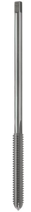
91 91 P Steel M Stainless Steel K Cast Iron N Non-Ferrous Metals S Titanium & Super Alloys H Hard Materials T430 VDI 3323 ISO • 1 P • 2 • 3 • 4 5 • 6 • 7 8 9 10 11 12 13 • 14.1 M 14.2 14.3 • 15 K 16 • 17 18 • 19 20 • 21 N • 22 • 23 • 24 25 • 26 27 • 28 29 30 31 S 32 33 34 35 36 37.1 37.2 37.3 37.4 37.5 • Optimal • Effective 38.1 H 38.2 39.1 39.2 40 41 0635 1/4 20 110 38 - 4.5 3.55 6 4 GH4 5.1 T430 0635 0794 5/16 18 125 43 - 6 4.5 7 4 GH5 6.6 T430 0794 0953 3/8 16 140 48 - 7 5.6 8 4 GH5 8.0 T430 0953 1270 1/2 13 180 59 - 9.5 7.5 10 4 GH6 10.8 T430 1270
Catalogue Code T430 Discount Group D0702 Material HSS Surface Finish Brt Sutton Designation Nut Geometry Extra Length Chamfer Bottoming Nut Tolerance 2B Size Ref. d1 TPI l1 l2 l3 d2 sq l4 z Limit drill ø Item #
UNC Contents Index
- General purpose use
- Suitable for materials up to 1000N/mm2
- Through & blind holes
-
92 92 P Steel M Stainless Steel K Cast Iron N Non-Ferrous Metals S Titanium & Super Alloys H Hard Materials T432 T431 VDI 3323 ISO • • 1 P • • 2 • • 3 • • 4 5 • • 6 • • 7 8 9 10 11 12 13 14.1 M 14.2 14.3 • • 15 K 16 • • 17 18 • • 19 20 • • 21 N • • 22 • • 23 • • 24 25 • • 26 27 • • 28 29 30 31 S 32 33 34 35 36 37.1 37.2 37.3 37.4 37.5 • Optimal • Effective 38.1 H 38.2 39.1 39.2 40 41 0251 #3 56 45 10 - 2.80 2.24 5 3 2.1 T431 0251 T432 0251 0284 #4 48 48 15 14.5 3.15 2.50 5 3 2.35 T431 0284 T432 0284 0318 #5 44 48 15 15 3.15 2.50 5 3 2.65 T431 0318 T432 0318 0351 #6 40 50 17 17.5 3.55 2.80 5 3 2.9 T431 0351 T432 0351 0417 #8 36 53 13 17 4.50 3.55 6 3 3.5 T431 0417 T432 0417 0476 3/16 32 (UNS) 58 16 22 5.00 4.00 7 3 4.0 T431 0476 T432 0476 0483 #10 32 58 16 22 5.00 4.00 7 3 4.1 T431 0483 T432 0483 0549 #12 28 62 17 23 5.60 4.50 7 3 4.6 T431 0549 T432 0549 0635 1/4 28 66 19 25 6.30 5.00 8 3 5.5 T431 0635 T432 0635 0794 5/16 24 72 22 30 8.00 6.30 9 4 6.9 T431 0794 T432 0794 0953 3/8 24 80 24 33 10.00 8.00 11 4 8.5 T431 0953 T432 0953 1111 7/16 20 85 25 - 8.00 6.30 9 4 9.8 T431 1111 T432 1111 1270 1/2 20 89 29 - 9.00 7.10 10 4 11.5 T431 1270 T432 1270 1429 9/16 18 95 30 - 11.20 9.00 12 4 12.8 T431 1429 T432 1429 1588 5/8 18 102 32 - 12.50 10.00 13 4 14.5 T431 1588 T432 1588 1905 3/4 16 112 37 - 14.00 11.20 14 4 17.5 T431 1905 T432 1905 2223 7/8 14 118 38 - 16.00 12.50 16 4 20.5 T431 2223 T432 2223 2540 1 12 130 45 - 18.00 14.00 18 4 23.5 T431 2540 T432 2540 2541 1 14 (UNS) 130 45 - 18.00 14.00 18 4 24.0 T431 2541 T432 2541 2858 1-1/8 12 138 48 - 20.00 16.00 20 4 26.5 T431 2858 T432 2858 3175 1-1/4 12 151 51 - 22.40 18.00 22 4 29.5 T431 3175 T432 3175 3810 1-1/2 12 170 60 - 28.00 22.40 26 4 36.0 T431 3810 T432 3810
Suitable for both hand and machine operations
Catalogue Code T431 T432 Discount Group D0702 D0702 Material HSS HSS Surface Finish Brt Brt Sutton Designation N N Geometry -Chamfer Taper Intermediate Nut Tolerance 2B 2B Size Ref. d1 TPI l1 l2 l3 d2 sq l4 z drill ø Item # Item # ISO Taps UNF, Straight Flute, N UNF Contents Index
- Depths up to approx. 1 x d1
93 0251 #3 56 45 10 - 2.80 2.24 5 3 2.1 T433 0251 • 0284 #4 48 48 15 14.5 3.15 2.50 5 3 2.35 T433 0284 T904 0284 0318 #5 44 48 15 15 3.15 2.50 5 3 2.65 T433 0318 T904 0318 0351 #6 40 50 17 17.5 3.55 2.80 5 3 2.9 T433 0351 T904 0351 0417 #8 36 53 13 17 4.50 3.55 6 3 3.5 T433 0417 T904 0417 0476 3/16 32 (UNS) 58 16 22 5.00 4.00 7 3 4.0 T433 0476 T904 0476 0483 #10 32 58 16 22 5.00 4.00 7 3 4.1 T433 0483 T904 0483 0549 #12 28 62 17 23 5.60 4.50 7 3 4.6 T433 0549 T904 0549 0635 1/4 28 66 19 25 6.30 5.00 8 3 5.5 T433 0635 T904 0635 0794 5/16 24 72 22 30 8.00 6.30 9 4 6.9 T433 0794 T904 0794 0953 3/8 24 80 24 33 10.00 8.00 11 4 8.5 T433 0953 T904 0953 1111 7/16 20 85 25 - 8.00 6.30 9 4 9.8 T433 1111 T904 1111 1270 1/2 20 89 29 - 9.00 7.10 10 4 11.5 T433 1270 T904 1270 1429 9/16 18 95 30 - 11.20 9.00 12 4 12.8 T433 1429 T904 1429 1588 5/8 18 102 32 - 12.50 10.00 13 4 14.5 T433 1588 T904 1588 1905 3/4 16 112 37 - 14.00 11.20 14 4 17.5 T433 1905 T904 1905 2223 7/8 14 118 38 - 16.00 12.50 16 4 20.5 T433 2223 T904 2223 2540 1 12 130 45 - 18.00 14.00 18 4 23.5 T433 2540 T904 2540 2541 1 14 (UNS) 130 45 - 18.00 14.00 18 4 24.0 T433 2541 T904 2541 2858 1-1/8 12 138 48 - 20.00 16.00 20 4 26.5 T433 2858 • 3175 1-1/4 12 151 51 - 22.40 18.00 22 4 29.5 T433 3175 • 3810 1-1/2 12 170 60 - 28.00 22.40 26 4 36.0 T433 3810 • P Steel M Stainless Steel K Cast Iron N Non-Ferrous Metals S Titanium & Super Alloys H Hard Materials T904 T433 VDI 3323 ISO • • 1 P • • 2 • • 3 • • 4 5 • • 6 • • 7 8 9 10 11 12 13 14.1 M 14.2 14.3 • • 15 K 16 • • 17 18 • • 19 20 • • 21 N • • 22 • • 23 • • 24 25 • • 26 27 • • 28 29 30 31 S 32 33 34 35 36 37.1 37.2 37.3 37.4 37.5 • Optimal • Effective 38.1 H 38.2 39.1 39.2 40 41 • Available on request as special manufacture. Subject to lead time. - General purpose use - Suitable for materials up to 1000N/mm2 - Through & blind holes
Suitable for both hand and machine operations - Depths up to approx. 1 x d1 Catalogue Code T433 T904 Discount Group D0702 D0702 Material HSS HSS Surface Finish Brt Brt Sutton Designation N N Geometry -Chamfer Bottoming Set Nut Tolerance 2B 2B Size Ref. d1 TPI l1 l2 l3 d2 sq l4 z drill ø Item # Item #
N UNF Contents Index
-
ISO Taps UNF, Straight Flute,
ISO Taps UNF, Straight Flute, N, Left Hand
- General purpose use
- Suitable for materials up to 1000N/mm2
- Through & blind holes
- Suitable for both hand and machine operations
- Depths up to approx. 1 x d1
94 94 P Steel M Stainless Steel K Cast Iron N Non-Ferrous Metals S Titanium & Super Alloys H Hard Materials T437 T436 VDI 3323 ISO • • 1 P • • 2 • • 3 • • 4 5 • • 6 • • 7 8 9 10 11 12 13 14.1 M 14.2 14.3 • • 15 K 16 • • 17 18 • • 19 20 • • 21 N • • 22 • • 23 • • 24 25 • • 26 27 • • 28 29 30 31 S 32 33 34 35 36 37.1 37.2 37.3 37.4 37.5 • Optimal • Effective 38.1 H 38.2 39.1 39.2 40 41 0635 1/4 28 66 19 25 6.30 5.00 8 3 GH3 5.5 T436 0635 T437 0635 0794 5/16 24 72 22 30 8.00 6.30 9 4 GH4 6.9 T436 0794 T437 0794 0953 3/8 24 80 24 33 10.00 8.00 11 4 GH4 8.5 T436 0953 T437 0953 1111 7/16 20 85 25 - 8.00 6.30 9 4 GH5 9.8 T436 1111 T437 1111 1270 1/2 20 89 29 - 9.00 7.10 10 4 GH5 11.5 T436 1270 T437 1270 1429 9/16 18 95 30 - 11.20 9.00 12 4 GH5 12.8 T436 1429 T437 1429 1588 5/8 18 102 32 - 12.50 10.00 13 4 GH5 14.5 T436 1588 T437 1588 1905 3/4 16 112 37 - 14.00 11.20 14 4 GH6 17.5 T436 1905 T437 1905
Catalogue Code T436 T437 Discount Group D0702 D0702 Material HSS HSS Surface Finish Brt Brt Sutton Designation N N Geometry Left Hand Left Hand Chamfer Taper Intermediate Nut Tolerance 2B LH 2B LH Size Ref. d1 TPI l1 l2 l3 d2 sq l4 z Limit drill ø Item # Item #
UNF Contents Index
ISO Taps UNF, Straight Flute, N, Left Hand
- General purpose use
- Suitable for materials up to 1000N/mm2
- Through & blind holes
-
95 0635 1/4 28 66 19 25 6.30 5.00 8 3 GH3 5.5 T438 0635 0794 5/16 24 72 22 30 8.00 6.30 9 4 GH4 6.9 T438 0794 0953 3/8 24 80 24 33 10.00 8.00 11 4 GH4 8.5 T438 0953 1111 7/16 20 85 25 - 8.00 6.30 9 4 GH5 9.8 T438 1111 1270 1/2 20 89 29 - 9.00 7.10 10 4 GH5 11.5 T438 1270 1429 9/16 18 95 30 - 11.20 9.00 12 4 GH5 12.8 T438 1429 1588 5/8 18 102 32 - 12.50 10.00 13 4 GH5 14.5 T438 1588 1905 3/4 16 112 37 - 14.00 11.20 14 4 GH6 17.5 T438 1905 P Steel M Stainless Steel K Cast Iron N Non-Ferrous Metals S Titanium & Super Alloys H Hard Materials T438 VDI 3323 ISO • 1 P • 2 • 3 • 4 5 • 6 • 7 8 9 10 11 12 13 14.1 M 14.2 14.3 • 15 K 16 • 17 18 • 19 20 • 21 N • 22 • 23 • 24 25 • 26 27 • 28 29 30 31 S 32 33 34 35 36 37.1 37.2 37.3 37.4 37.5 • Optimal • Effective 38.1 H 38.2 39.1 39.2 40 41
Suitable
for both hand and machine operations
Catalogue Code T438 Discount Group D0702 Material HSS Surface Finish Brt Sutton Designation N Geometry Left Hand Chamfer Bottoming Nut Tolerance 2B LH Size Ref. d1 TPI l1 l2 l3 d2 sq l4 z Limit drill ø Item #
- Depths up to approx. 1 x d1
UNF Contents Index
- General purpose use
- Suitable for materials up to 1000N/mm2
- Through & blind holes
- Suitable for both hand and machine operations
- Depths up to approx. 1 x d1
Series
Tyre Valve Tap (UNS)
Stitching Tap
96 P Steel M Stainless Steel K Cast Iron N Non-Ferrous Metals S Titanium & Super Alloys H Hard Materials T446 T445 VDI 3323 ISO • • 1 P • • 2 • • 3 • • 4 5 • • 6 • • 7 8 9 10 11 12 13 14.1 M 14.2 14.3 • • 15 K 16 • • 17 18 • • 19 20 • • 21 N • • 22 • • 23 • • 24 25 • • 26 27 • • 28 29 30 31 S 32 33 34 35 36 37.1 37.2 37.3 37.4 37.5 • Optimal • Effective 38.1 H 38.2 39.1 39.2 40 41 0635 1/4 32 66 19 25 6.30 5.00 8 3 GH3 5.6 T445 0635 T446 0635 0794 5/16 32 72 22 30 8.00 6.30 9 4 GH4 7.2 T445 0794 T446 0794 0953 3/8 32 80 24 33 10.00 8.00 11 4 GH4 8.8 T445 0953 T446 0953 1270 1/2 28 89 29 - 9.00 7.10 10 4 GH5 11.8 T445 1270 T446 1270 1588 5/8 24 102 32 - 12.50 10.00 13 4 GH5 14.75 T445 1588 T446 1588 1905 3/4 20 112 37 - 14.00 11.20 14 4 GH6 18.0 T445 1905 T446 1905 2540 1 20 130 45 - 18.00 14.00 18 4 GH7 24.2 T445 2540 T446 2540 0533 5V1 36 62 17 23 5.60 4.50 7 3 - 4.6 • • 0655 #1 64 36 - 8.08 6.15 9.5 4 - 5.0 • • • Available on request as special manufacture. Subject to lead time.
Catalogue Code T445 T446 Discount Group D0702 D0702 Material HSS HSS Surface Finish Brt Brt Sutton Designation N N Geometry Extra Fine Extra Fine Chamfer Taper Intermediate Nut Tolerance 2B 2B Size Ref. d1 TPI l1 l2 l3 d2 sq l4 z Limit drill ø Item # Item #
ISO Taps UNEF, Straight Flute, N UNEF
UNEF UNEF Contents Index
ISO Taps UNEF, Straight Flute, N
- General purpose use
- Suitable for materials up to 1000N/mm2
- Through & blind holes
- Suitable for both hand and machine operations
- Depths up to approx. 1 x d1
Tyre Valve Tap (UNS) Stitching Tap UNEF
97 P Steel M Stainless Steel K Cast Iron N Non-Ferrous Metals S Titanium & Super Alloys H Hard Materials T490 T489 T447 VDI 3323 ISO • • • 1 P • • • 2 • • • 3 • • • 4 5 • • • 6 • • • 7 8 9 10 11 12 13 14.1 M 14.2 14.3 • • • 15 K 16 • • • 17 18 • • • 19 20 • • • 21 N • • • 22 • • • 23 • • • 24 25 • • • 26 27 • • • 28 29 30 31 S 32 33 34 35 36 37.1 37.2 37.3 37.4 37.5 • Optimal • Effective 38.1 H 38.2 39.1 39.2 40 41 0635 1/4 32 66 19 25 6.30 5.00 8 3 GH3 5.6 T447 0635 0794 5/16 32 72 22 30 8.00 6.30 9 4 GH4 7.2 T447 0794 0953 3/8 32 80 24 33 10.00 8.00 11 4 GH4 8.8 T447 0953 1270 1/2 28 89 29 - 9.00 7.10 10 4 GH5 11.8 T447 1270 1588 5/8 24 102 32 - 12.50 10.00 13 4 GH5 14.75 T447 1588 1905 3/4 20 112 37 - 14.00 11.20 14 4 GH6 18.0 T447 1905 2540 1 20 130 45 - 18.00 14.00 18 4 GH7 24.2 T447 2540 T489 0533 5V1 36 62 17 23 5.60 4.50 7 3 - 4.6 T489 0533 T490 0655 #1 64 36 - 8.08 6.15 9.5 4 - 5.0 T490 0655
Catalogue Code T447
Group D0702 Material HSS
Finish Brt Sutton Designation N Geometry Extra Fine Chamfer Bottoming Nut Tolerance 2B Size Ref. d1 TPI l1 l2 l3 d2 sq l4 z Limit drill ø Item #
Discount
Surface
UNEF Series
UNEF Contents Index
- General purpose use
- Suitable for materials up to 1000N/mm2
- Through holes
- Depths up to approx. 3 x d1
98 98 98 P Steel M Stainless Steel K Cast Iron N Non-Ferrous Metals S Titanium & Super Alloys H Hard Materials T440 T439 VDI 3323 ISO • • 1 P • • 2 • • 3 • • 4 5 • • 6 • • 7 8 9 10 11 • 12 13 • • 14.1 M • • 14.2 14.3 15 K 16 • • 17 • • 18 • • 19 20 • 21 N • 22 • 23 • 24 25 • 26 • 27 28 29 30 31 S 32 33 34 35 36 37.1 37.2 37.3 37.4 37.5 • Optimal • Effective 38.1 H 38.2 39.1 39.2 • • 40 41 0483 #10 32 58 16 22 5.00 4.00 7 3 GH3 4.1 T439 0483 T440 0483 0635 1/4 28 66 19 25 6.30 5.00 8 3 GH3 5.5 T439 0635 T440 0635 0794 5/16 24 72 22 30 8.00 6.30 9 3 GH4 6.9 T439 0794 T440 0794 0953 3/8 24 80 24 33 10.00 8.00 11 3 GH4 8.5 T439 0953 T440 0953 1111 7/16 20 85 25 - 8.00 6.30 9 3 GH5 9.8 T439 1111 T440 1111 1270 1/2 20 89 29 - 9.00 7.10 10 3 GH5 11.5 T439 1270 T440 1270 1588 5/8 18 102 32 - 12.50 10.00 13 3 GH5 12.8 T439 1588 T440 1588 1905 3/4 16 112 37 - 14.00 11.20 14 4 GH6 17.5 T439 1905 T440 1905 2223 7/8 14 118 38 - 16.00 12.50 16 4 GH6 20.5 • T440 2223 2540 1 12 130 45 - 18.00 14.00 18 4 GH7 23.5 • T440 2540 •
Available on request as special manufacture. Subject to lead time.
Catalogue Code T439 T440 Discount Group D0702 D0702 Material HSSE HSSE Surface Finish Brt Blu Sutton Designation N N Geometry -Chamfer Intermediate Intermediate Nut Tolerance 2B 2B Size Ref. d1 TPI l1 l2 l3 d2 sq l4 z Limit drill ø Item # Item # ISO Taps UNF, Gun, N UNF Contents Index
- General purpose use
- Suitable for materials up to 1000N/mm2
- Through holes
- Depths up to approx. 3 x d1 Catalogue Code T441 Discount Group D0706
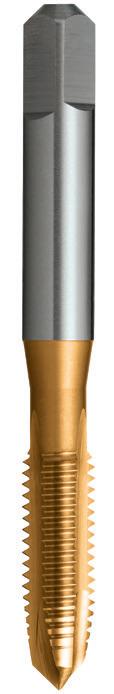
99 99 0483 #10 32 58 16 22 5.00 4.00 7 3 GH3 4.1 T441 0483 0635 1/4 28 66 19 25 6.30 5.00 8 3 GH3 5.5 T441 0635 0794 5/16 24 72 22 30 8.00 6.30 9 3 GH4 6.9 T441 0794 0953 3/8 24 80 24 33 10.00 8.00 11 3 GH4 8.5 T441 0953 1111 7/16 20 85 25 - 8.00 6.30 9 3 GH5 9.8 • 1270 1/2 20 89 29 - 9.00 7.10 10 3 GH5 11.5 T441 1270 1588 5/8 18 102 32 - 12.50 10.00 13 3 GH5 12.8 T441 1588 1905 3/4 16 112 37 - 14.00 11.20 14 4 GH6 17.5 T441 1905 2223 7/8 14 118 38 - 16.00 12.50 16 4 GH6 20.5 • 2540 1 12 130 45 - 18.00 14.00 18 4 GH7 23.5 • P Steel M Stainless Steel K Cast Iron N Non-Ferrous Metals S Titanium & Super Alloys H Hard Materials T441 VDI 3323 ISO • 1 P • 2 • 3 • 4 • 5 • 6 • 7 • 8 9 • 10 11 • 12 • 13 • 14.1 M • 14.2 14.3 15 K 16 • 17 • 18 • 19 20 • 21 N • 22 • 23 • 24 • 25 • 26 • 27 28 29 30 31 S 32 33 34 35 36 37.1 37.2 37.3 37.4 37.5 • Optimal • Effective 38.1 H 38.2 39.1 39.2 • 40 41 • Available on request as special manufacture. Subject to lead time.
Material
Surface Finish TiN Sutton Designation N GeometryChamfer Intermediate Nut Tolerance 2B Size Ref. d1 TPI l1 l2 l3 d2 sq l4 z Limit drill ø Item #
HSSE
N UNF Contents Index
ISO Taps UNF, Gun,
- General purpose use
- Suitable for materials up to 1000N/mm2
- Blind holes
- Depths up to approx. 2.5 x d1
100 100 100 P Steel M Stainless Steel K Cast Iron N Non-Ferrous Metals S Titanium & Super Alloys H Hard Materials T443 T442 VDI 3323 ISO • • 1 P • • 2 • • 3 • • 4 • 5 • • 6 • 7 • 8 9 • 10 11 • 12 • 13 • • 14.1 M • • 14.2 14.3 15 K 16 • • 17 • • 18 19 20 • • 21 N • • 22 • • 23 • • 24 • 25 • 26 • • 27 • 28 29 30 31 S 32 33 34 35 36 37.1 37.2 37.3 37.4 37.5 • Optimal • Effective 38.1 H 38.2 39.1 39.2 • • 40 41 0483 #10 32 58 11 22 5.00 4.00 7 3 GH3 4.1 T442 0483 T443 0483 0635 1/4 28 66 10 25 6.30 5.00 8 3 GH3 5.5 T442 0635 T443 0635 0794 5/16 24 72 13 30 8.00 6.30 9 3 GH4 6.9 T442 0794 T443 0794 0953 3/8 24 80 16 33 10.00 8.00 11 3 GH4 8.5 T442 0953 T443 0953 1111 7/16 20 85 18 - 8.00 6.30 9 3 GH5 9.8 T442 1111 • 1270 1/2 20 89 20 - 9.00 7.10 10 3 GH5 11.5 T442 1270 T443 1270 1588 5/8 18 102 20 - 12.50 10.00 13 3 GH5 12.8 T442 1588 T443 1588 1905 3/4 16 112 25 - 14.00 11.20 14 4 GH6 17.5 T442 1905 T443 1905 • Available on request as special manufacture. Subject to lead time.
ISO Taps
Spiral Flute, N Catalogue Code T442 T443 Discount Group D0702 D0706 Material HSSE HSSE Surface Finish Brt TiN Sutton Designation N N Geometry R40 R40 Chamfer Bottoming Bottoming Nut Tolerance 2B 2B Size Ref d1 TPI l1 l2 l3 d2 sq l4 z Limit drill ø Item # Item # UNF Contents Index
UNF,
ISO Taps UNF, Forming, Single Coolant Groove
- For cold forming of threads in materials with good flow characteristics
- Through or blind holes
- Depths up to approx. 1.5 x d1
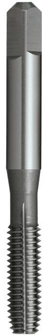
101 101 P Steel M Stainless Steel K Cast Iron N Non-Ferrous Metals S Titanium & Super Alloys H Hard Materials T444 VDI 3323 ISO • 1 P • 2 • 3 • 4 5 • 6 7 8 9 10 11 12 13 14.1 M 14.2 14.3 15 K 16 17 18 19 20 • 21 N • 22 • 23 • 24 25 • 26 27 • 28 29 30 31 S 32 33 34 35 36 37.1 37.2 37.3 37.4 37.5 • Optimal • Effective 38.1 H 38.2 39.1 39.2 40 41 0635 1/4 28 66 19 25 6.30 5.00 7 - GH7 6.0 T444 0635 0794 5/16 24 72 22 30 8.00 6.30 8 - GH7 7.5 T444 0794 0953 3/8 24 80 24 33 10.00 8.00 9 - GH7 9.0 T444 0953 1270 1/2 20 89 29 - 9.00 7.10 10 - GH8 12.1 T444 1270
Catalogue Code T444 Discount Group D0702 Material HSSE Surface Finish Brt Sutton Designation N Geometry Single Coolant Groove Chamfer Short Nut Tolerance 2B Size Ref. d1 TPI l1 l2 l3 d2 sq l4 z Limit drill ø Item # UNF Contents Index
- General purpose use
- Suitable for materials up to 1000N/mm2
- Through & blind holes
- Suitable for both hand and machine operations
- Depths up to approx. 1 x d1
102 P Steel M Stainless Steel K Cast Iron N Non-Ferrous Metals S Titanium & Super Alloys H Hard Materials T449 T448 VDI 3323 ISO • • 1 P • • 2 • • 3 • • 4 5 • • 6 • • 7 8 9 10 11 12 13 14.1 M 14.2 14.3 • • 15 K 16 • • 17 18 • • 19 20 • • 21 N • • 22 • • 23 • • 24 25 • • 26 27 • • 28 29 30 31 S 32 33 34 35 36 37.1 37.2 37.3 37.4 37.5 • Optimal • Effective 38.1 H 38.2 39.1 39.2 40 41 2858 1-1/8 8 138 48 - 20.00 16.00 20 4 25.5 T448 2858 T449 2858 3175 1-1/4 8 151 51 - 22.40 18.00 22 4 28.5 T448 3175 T449 3175 3493 1-3/8 8 162 57 - 25.00 20.00 24 4 31.75 T448 3493 T449 3493 3810 1-1/2 8 170 60 - 28.00 22.40 26 4 35.0 T448 3810 T449 3810 4128 1-5/8 8 170 60 - 28.00 22.40 26 4 38.0 T448 4128 T449 4128 4445 1-3/4 8 187 67 - 31.50 25.00 28 4 41.5 T448 4445 T449 4445 4763 1-7/8 8 187 67 - 31.50 25.00 28 4 44.5 T448 4763 T449 4763 5080 2 8 200 70 - 35.50 28.00 31 4 47.5 T448 5080 T449 5080 6033
40.00
57.15 • •
2-3/8 8 221 76 -
31.50 34 6
ISO Taps 8UN, Straight Flute, N Catalogue Code T448 T449 Discount Group D0702 D0702 Material HSS HSS Surface Finish Brt Brt Sutton Designation N N Geometry Extra Fine Extra Fine Chamfer Taper Intermediate Limit & Nut Tolerance GH8/2B GH8/2B Size Ref. d1 TPI l1 l2 l3 d2 sq l4 z drill ø Item # Item # • Available on request as special manufacture. Subject to lead time. 8UN Contents Index
103 2858 1-1/8 8 138 48 - 20.00 16.00 20 4 25.5 T450 2858 T910 2858 3175 1-1/4 8 151 51 - 22.40 18.00 22 4 28.5 T450 3175 T910 3175 3493 1-3/8 8 162 57 - 25.00 20.00 24 4 31.75 T450 3493 T910 3493 3810 1-1/2 8 170 60 - 28.00 22.40 26 4 35.0 T450 3810 T910 3810 4128 1-5/8 8 170 60 - 28.00 22.40 26 4 38.0 T450 4128 T910 4128 4445 1-3/4 8 187 67 - 31.50 25.00 28 4 41.5 T450 4445 T910 4445 4763 1-7/8 8 187 67 - 31.50 25.00 28 4 44.5 T450 4763 T910 4763 5080 2 8 200 70 - 35.50 28.00 31 4 47.5 T450 5080 T910 5080 6033 2-3/8 8 221 76 - 40.00 31.50 34 6 57.15 • • P Steel M Stainless Steel K Cast Iron N Non-Ferrous Metals S Titanium & Super Alloys H Hard Materials T910 T450 VDI 3323 ISO • • 1 P • • 2 • • 3 • • 4 5 • • 6 • • 7 8 9 10 11 12 13 14.1 M 14.2 14.3 • • 15 K 16 • • 17 18 • • 19 20 • • 21 N • • 22 • • 23 • • 24 25 • • 26 27 • • 28 29 30 31 S 32 33 34 35 36 37.1 37.2 37.3 37.4 37.5 • Optimal • Effective 38.1 H 38.2 39.1 39.2 40 41 - General purpose use
Suitable for materials up to 1000N/mm2
Through & blind holes
Suitable for both hand and machine operations
Depths up to approx. 1 x d1 ISO Taps 8UN, Straight Flute, N Catalogue Code T450 T910 Discount Group D0702 D0702 Material HSS HSS Surface Finish Brt Brt Sutton Designation N N Geometry Extra Fine Extra Fine Chamfer Bottoming Set Limit & Nut Tolerance GH8/2B GH8/2B Size Ref. d1 TPI l1 l2 l3 d2 sq l4 z drill ø Item # Item # • Available on request as special manufacture. Subject to lead time. 8UN Contents Index
-
-
-
-
- General purpose use
- Suitable for materials up to 1000N/mm2
- Through & blind holes
- Suitable for both hand and machine operations
- Depths up to approx. 1 x d1
104 P Steel M Stainless Steel K Cast Iron N Non-Ferrous Metals S Titanium & Super Alloys H Hard Materials T452 T451 VDI 3323 ISO • • 1 P • • 2 • • 3 • • 4 5 • • 6 • • 7 8 9 10 11 12 13 14.1 M 14.2 14.3 • • 15 K 16 • • 17 18 • • 19 20 • • 21 N • • 22 • • 23 • • 24 25 • • 26 27 • • 28 29 30 31 S 32 33 34 35 36 37.1 37.2 37.3 37.4 37.5 • Optimal • Effective 38.1 H 38.2 39.1 39.2 40 41 0238 3/32 48(WHIT) 45 10 - 2.80 2.24 5 3 1.85 T451 0238 T452 0238 0318 1/8 40 48 15 15 3.15 2.50 5 3 2.55 T451 0318 T452 0318 0397 5/32 32(WHIT) 53 17 17 4.00 3.15 6 3 3.2 T451 0397 T452 0397 0476 3/16 24 58 16 22 5.00 4.00 7 3 3.7 T451 0476 T452 0476 0556 7/32 24(WHIT) 62 17 23 5.60 4.50 7 3 4.5 T451 0556 T452 0556 0635 1/4 20 66 19 25 6.30 5.00 8 3 5.1 T451 0635 T452 0635 0794 5/16 18 72 22 30 8.00 6.30 9 4 6.5 T451 0794 T452 0794 0953 3/8 16 80 24 33 10.00 8.00 11 4 7.9 T451 0953 T452 0953 1111 7/16 14 85 25 - 8.00 6.30 9 4 9.3 T451 1111 T452 1111 1270 1/2 12 89 29 - 9.00 7.10 10 4 10.5 T451 1270 T452 1270 1429 9/16 12 95 30 - 11.20 9.00 12 4 12.1 T451 1429 T452 1429 1588 5/8 11 102 32 - 12.50 10.00 13 4 13.5 T451 1588 T452 1588 1905 3/4 10 112 37 - 14.00 11.20 14 4 16.25 T451 1905 T452 1905 2223 7/8 9 118 38 - 16.00 12.50 16 4 19.25 T451 2223 T452 2223 2540 1 8 130 45 - 18.00 14.00 18 4 22.0 T451 2540 T452 2540 2858 1-1/8 7 138 48 - 20.00 16.00 20 4 24.75 T451 2858 T452 2858 3175 1-1/4 7 151 51 - 22.40 18.00 22 4 28.0 T451 3175 T452 3175 3810 1-1/2 6 170 60 - 28.00 22.40 26 4 33.5 T451 3810 T452 3810 4445 1-3/4 5 187 67 - 31.50 25.00 28 4 39.0 T451 4445 T452 4445 5080 2 4-1/2 200 70 - 35.50 28.00 31 4 44.5 T451 5080 T452 5080
Catalogue Code T451 T452 Discount Group D0702 D0702 Material HSS HSS Surface Finish Brt Brt Sutton Designation N N Geometry -Chamfer Taper Intermediate Limit & Nut Tolerance Z3 Medium Z3 Medium Size Ref. d1 TPI l1 l2 l3 d2 sq l4 z drill ø Item # Item # ISO Taps BSW, Straight Flute, N BSW Contents Index
105 105 0238 3/32 48(WHIT) 45 10 - 2.80 2.24 5 3 1.85 T453 0238 T905 0238 0318 1/8 40 48 15 15 3.15 2.50 5 3 2.55 T453 0318 T905 0318 0397 5/32 32(WHIT) 53 17 17 4.00 3.15 6 3 3.2 T453 0397 T905 0397 0476 3/16 24 58 16 22 5.00 4.00 7 3 3.7 T453 0476 T905 0476 0556 7/32 24(WHIT) 62 17 23 5.60 4.50 7 3 4.5 T453 0556 T905 0556 0635 1/4 20 66 19 25 6.30 5.00 8 3 5.1 T453 0635 T905 0635 0794 5/16 18 72 22 30 8.00 6.30 9 4 6.5 T453 0794 T905 0794 0953 3/8 16 80 24 33 10.00 8.00 11 4 7.9 T453 0953 T905 0953 1111 7/16 14 85 25 - 8.00 6.30 9 4 9.3 T453 1111 T905 1111 1270 1/2 12 89 29 - 9.00 7.10 10 4 10.5 T453 1270 T905 1270 1429 9/16 12 95 30 - 11.20 9.00 12 4 12.1 T453 1429 T905 1429 1588 5/8 11 102 32 - 12.50 10.00 13 4 13.5 T453 1588 T905 1588 1905 3/4 10 112 37 - 14.00 11.20 14 4 16.25 T453 1905 T905 1905 2223 7/8 9 118 38 - 16.00 12.50 16 4 19.25 T453 2223 T905 2223 2540 1 8 130 45 - 18.00 14.00 18 4 22.0 T453 2540 T905 2540 2858 1-1/8 7 138 48 - 20.00 16.00 20 4 24.75 T453 2858 • 3175 1-1/4 7 151 51 - 22.40 18.00 22 4 28.0 T453 3175 • 3810 1-1/2 6 170 60 - 28.00 22.40 26 4 33.5 T453 3810 • 4445 1-3/4 5 187 67 - 31.50 25.00 28 4 39.0 T453 4445 • 5080 2 4-1/2 200 70 - 35.50 28.00 31 4 44.5 T453 5080 • P Steel M Stainless Steel K Cast Iron N Non-Ferrous Metals S Titanium & Super Alloys H Hard Materials T905 T453 VDI 3323 ISO • • 1 P • • 2 • • 3 • • 4 5 • • 6 • • 7 8 9 10 11 12 13 14.1 M 14.2 14.3 • • 15 K 16 • • 17 18 • • 19 20 • • 21 N • • 22 • • 23 • • 24 25 • • 26 27 • • 28 29 30 31 S 32 33 34 35 36 37.1 37.2 37.3 37.4 37.5 • Optimal • Effective 38.1 H 38.2 39.1 39.2 40 41 • Available on request as special manufacture. Subject to lead time. - General purpose use
Suitable for materials up to 1000N/mm2 - Through & blind holes
Suitable for both hand and machine operations - Depths up to approx. 1 x d1 Catalogue Code T453 T905 Discount Group D0702 D0702 Material HSS HSS Surface Finish Brt Brt Sutton Designation N N Geometry -Chamfer Bottoming Set Limit & Nut Tolerance Z3 Medium Z3 Medium Size Ref. d1 TPI l1 l2 l3 d2 sq l4 z drill ø Item # Item #
Straight Flute, N BSW Contents Index
-
-
ISO Taps BSW,
BSW,
- General purpose use
- Suitable for materials up to 1000N/mm2
- Through & blind holes
- Suitable for both hand and machine operations
- Depths up to approx. 1 x d1
Catalogue Code T456
Discount Group D0702
Material HSS
Surface Finish Brt
Sutton Designation N
Geometry Left Hand
Chamfer
Bottoming
Limit & Nut Tolerance Z3 LH Medium
106 106 P Steel M Stainless Steel K Cast Iron N Non-Ferrous Metals S Titanium & Super Alloys H Hard Materials T456 VDI 3323 ISO • 1 P • 2 • 3 • 4 5 • 6 • 7 8 9 10 11 12 13 14.1 M 14.2 14.3 • 15 K 16 • 17 18 • 19 20 • 21 N • 22 • 23 • 24 25 • 26 27 • 28 29 30 31 S 32 33 34 35 36 37.1 37.2 37.3 37.4 37.5 • Optimal • Effective 38.1 H 38.2 39.1 39.2 40 41 0635 1/4 20 66 19 25 6.30 5.00 8 3 5.1 T456 0635 0794 5/16 18 72 22 30 8.00 6.30 9 4 6.5 T456 0794 0953 3/8 16 80 24 33 10.00 8.00 11 4 7.9 T456 0953 1111 7/16 14 85 25 - 8.00 6.30 9 4 9.3 T456 1111 1270 1/2 12 89 29 - 9.00 7.10 10 4 10.5 T456 1270 1429 9/16 12 95 30 - 11.20 9.00 12 4 12.1 T456 1429 1588 5/8 11 102 32 - 12.50 10.00 13 4 13.5 T456 1588 1905 3/4 10 112 37 - 14.00 11.20 14 4 16.25 T456 1905
ISO Taps
Straight Flute, N, Left Hand
Size Ref. d1 TPI l1 l2 l3 d2 sq l4 z drill ø Item # BSW Contents Index
- General purpose use
- Suitable for materials up to 1000N/mm2
- Through holes
- Depths up to approx. 3 x d1
107 107 107 P Steel M Stainless Steel K Cast Iron N Non-Ferrous Metals S Titanium & Super Alloys H Hard Materials T458 T457 VDI 3323 ISO • • 1 P • • 2 • • 3 • • 4 5 • • 6 • • 7 8 9 10 11 • 12 13 • • 14.1 M • • 14.2 14.3 15 K 16 • • 17 • • 18 • • 19 20 • 21 N • 22 • 23 • 24 25 • 26 • 27 28 29 30 31 S 32 33 34 35 36 37.1 37.2 37.3 37.4 37.5 • Optimal • Effective 38.1 H 38.2 39.1 39.2 • • 40 41 0318 1/8 40 48 15 15 3.15 2.50 5 3 2.55 T457 0318 T458 0318 0397 5/32 32(WHIT) 53 17 17 4.00 3.15 6 3 3.2 T457 0397 T458 0397 0476 3/16 24 58 16 22 5.00 4.00 7 3 3.7 T457 0476 T458 0476 0635 1/4 20 66 19 25 6.30 5.00 8 3 5.1 T457 0635 T458 0635 0794 5/16 18 72 22 30 8.00 6.30 9 3 6.5 T457 0794 T458 0794 0953 3/8 16 80 24 33 10.00 8.00 11 3 7.9 T457 0953 T458 0953 1111 7/16 14 85 25 - 8.00 6.30 9 3 9.3 T457 1111 T458 1111 1270 1/2 12 89 29 - 9.00 7.10 10 3 10.5 T457 1270 T458 1270 1588 5/8 11 102 32 - 12.50 10.00 13 3 13.5 T457 1588 T458 1588 1905 3/4 10 112 37 - 14.00 11.20 14 4 16.25 T457 1905 T458 1905 2223 7/8 9 118 38 - 16.00 12.50 16 4 19.25 • T458 2223 2540 1 8 130 45 - 18.00 14.00 18 4 22.0 • T458 2540 • Available on request as special manufacture. Subject to lead time.
Catalogue Code T457 T458 Discount Group D0702 D0702 Material HSSE HSSE Surface Finish Brt Blu Sutton Designation N N Geometry -Chamfer Intermediate Intermediate Limit & Nut Tolerance Z3 Medium Z3 Medium Size Ref. d1 TPI l1 l2 l3 d2 sq l4 z drill ø Item # Item # ISO Taps BSW, Gun, N BSW Contents Index
-
- Depths up to approx. 3 x d1
Catalogue Code T459
Discount Group D0706
Material HSSE
Surface Finish TiN
108 108 0318 1/8 40 48 15 15 3.15 2.50 5 3 2.55 T459 0318 0397 5/32 32(WHIT) 53 17 17 4.00 3.15 6 3 3.2 T459 0397 0476 3/16 24 58 16 22 5.00 4.00 7 3 3.7 T459 0476 0635 1/4 20 66 19 25 6.30 5.00 8 3 5.1 T459 0635 0794 5/16 18 72 22 30 8.00 6.30 9 3 6.5 T459 0794 0953 3/8 16 80 24 33 10.00 8.00 11 3 7.9 T459 0953 1111 7/16 14 85 25 - 8.00 6.30 9 3 9.3 • 1270 1/2 12 89 29 - 9.00 7.10 10 3 10.5 T459 1270 1588 5/8 11 102 32 - 12.50 10.00 13 3 13.5 T459 1588 1905 3/4 10 112 37 - 14.00 11.20 14 4 16.25 T459 1905 2223 7/8 9 118 38 - 16.00 12.50 16 4 19.25 • 2540 1 8 130 45 - 18.00 14.00 18 4 22.0 • P Steel M Stainless Steel K Cast Iron N Non-Ferrous Metals S Titanium & Super Alloys H Hard Materials T459 VDI 3323 ISO • 1 P • 2 • 3 • 4 • 5 • 6 • 7 • 8 9 • 10 11 • 12 • 13 • 14.1 M • 14.2 14.3 15 K 16 • 17 • 18 • 19 20 • 21 N • 22 • 23 • 24 • 25 • 26 • 27 28 29 30 31 S 32 33 34 35 36 37.1 37.2 37.3 37.4 37.5 • Optimal • Effective 38.1 H 38.2 39.1 39.2 • 40 41 • Available on request as special manufacture. Subject to lead time.
General purpose use
-
up
1000N/mm2
Suitable for materials
to
- Through holes
Intermediate Limit & Nut
Size Ref. d1 TPI l1 l2 l3 d2 sq l4 z drill ø Item # ISO Taps BSW, Gun, N BSW Contents Index
Sutton Designation N GeometryChamfer
Tolerance Z3 Medium
- General purpose use
- Suitable for materials up to 1000N/mm2
- Blind holes
- Depths up to approx. 2.5 x d1
109 109 109 P Steel M Stainless Steel K Cast Iron N Non-Ferrous Metals S Titanium & Super Alloys H Hard Materials T461 T460 VDI 3323 ISO • • 1 P • • 2 • • 3 • • 4 5 • • 6 • 7 8 9 10 11 • 12 13 • • 14.1 M • • 14.2 14.3 15 K 16 • • 17 • • 18 19 20 • 21 N • 22 • 23 • 24 25 • 26 • 27 • 28 29 30 31 S 32 33 34 35 36 37.1 37.2 37.3 37.4 37.5 • Optimal • Effective 38.1 H 38.2 39.1 39.2 • • 40 41 0318 1/8 40 48 6 15 3.15 2.50 5 3 2.55 T460 0318 • 0397 5/32 32(WHIT) 53 7 17 4.00 3.15 6 3 3.2 T460 0397 • 0476 3/16 24 58 11 22 5.00 4.00 7 3 3.7 T460 0476 • 0635 1/4 20 66 10 25 6.30 5.00 8 3 5.1 T460 0635 T461 0635 0794 5/16 18 72 13 30 8.00 6.30 9 3 6.5 T460 0794 T461 0794 0953 3/8 16 80 16 33 10.00 8.00 11 3 7.9 T460 0953 T461 0953 1111 7/16 14 85 18 - 8.00 6.30 9 3 9.3 T460 1111 T461 1111 1270 1/2 12 89 20 - 9.00 7.10 10 3 10.5 T460 1270 T461 1270 1588 5/8 11 102 20 - 12.50 10.00 13 3 13.5 T460 1588 T461 1588 1905 3/4 10 112 25 - 14.00 11.20 14 4 16.25 T460 1905 T461 1905 2223 7/8 9 118 28 - 16.00 12.50 16 4 19.25 T460 2223 • 2540 1 8 130 35 - 18.00 14.00 18 4 22.0 T460 2540 • • Available on request as special manufacture. Subject to lead time.
Spiral Flute, N Catalogue Code T460 T461 Discount Group D0702 D0702 Material HSSE HSSE Surface Finish Brt Blu Sutton Designation N N Geometry R40 R40 Chamfer Bottoming Bottoming Limit & Nut Tolerance Z3 Medium Z3 Medium Size Ref. d1 TPI l1 l2 l3 d2 sq l4 z drill ø Item # Item # BSW Contents Index
ISO Taps BSW,
Catalogue Code T462
Discount Group D0706
Material HSSE
110 110 0318 1/8 40 48 6 15 3.15 2.50 5 3 2.55 • 0397 5/32 32(WHIT) 53 7 17 4.00 3.15 6 3 3.2 • 0476 3/16 24 58 11 22 5.00 4.00 7 3 3.7 T462 0476 0635 1/4 20 66 10 25 6.30 5.00 8 3 5.1 T462 0635 0794 5/16 18 72 13 30 8.00 6.30 9 3 6.5 T462 0794 0953 3/8 16 80 16 33 10.00 8.00 11 3 7.9 T462 0953 1111 7/16 14 85 18 - 8.00 6.30 9 3 9.3 • 1270 1/2 12 89 20 - 9.00 7.10 10 3 10.5 T462 1270 1588 5/8 11 102 20 - 12.50 10.00 13 3 13.5 T462 1588 1905 3/4 10 112 25 - 14.00 11.20 14 4 16.25 • 2223 7/8 9 118 28 - 16.00 12.50 16 4 19.25 • 2540 1 8 130 35 - 18.00 14.00 18 4 22.0 • P Steel M Stainless Steel K Cast Iron N Non-Ferrous Metals S Titanium & Super Alloys H Hard Materials T462 VDI 3323 ISO • 1 P • 2 • 3 • 4 • 5 • 6 • 7 • 8 9 • 10 11 • 12 • 13 • 14.1 M • 14.2 14.3 15 K 16 • 17 • 18 19 20 • 21 N • 22 • 23 • 24 • 25 26 • 27 28 29 30 31 S 32 33 34 35 36 37.1 37.2 37.3 37.4 37.5 • Optimal • Effective 38.1 H 38.2 39.1 39.2 • 40 41 • Available on request as special manufacture. Subject to lead time. - General purpose use
Suitable for materials up to 1000N/mm2
Blind holes
Depths up to approx. 2.5 x d1 ISO Taps BSW, Spiral Flute, N
-
-
-
Limit & Nut
Medium Size Ref. d1 TPI l1 l2 l3 d2 sq l4 z drill ø Item # BSW Contents Index
Surface Finish TiN Sutton Designation N Geometry R40 Chamfer Bottoming
Tolerance Z3
ISO Taps BSW, Forming, Single Coolant Groove
111 111 111 P Steel M Stainless Steel K Cast Iron N Non-Ferrous Metals S Titanium & Super Alloys H Hard Materials T464 T463 VDI 3323 ISO • • 1 P • • 2 • • 3 • • 4 5 • • 6 • 7 8 9 10 11 12 13 • 14.1 M 14.2 14.3 15 K 16 17 18 19 20 • • 21 N • • 22 • • 23 • • 24 25 • • 26 27 • • 28 29 30 31 S 32 33 34 35 36 37.1 37.2 37.3 37.4 37.5 • Optimal • Effective 38.1 H 38.2 39.1 39.2 40 41 0318 1/8 40 48 15 15 3.15 2.50 5 - 2.9 T463 0318 • 0397 5 /32 32(WHIT) 53 17 17 4.00 3.15 6 - 3.6 T463 0397 T464 0397 0476 3/16 24 58 16 22 5.00 4.00 7 - 4.3 T463 0476 T464 0476 0635 1/4 20 66 19 25 6.30 5.00 8 - 5.8 T463 0635 • 0794 5/16 18 72 22 30 8.00 6.30 9 - 7.3 T463 0794 • 0953 3/8 16 80 24 33 10.00 8.00 11 - 8.8 T463 0953 • • Available on request as special manufacture. Subject to lead time. - For cold forming of threads in materials with good flow characteristics - Through or blind holes
Depths up to approx. 1.5 x d1
TiN for longer tool life
-
-
Catalogue Code T463 T464 Discount Group D0702 D0706 Material HSSE HSSE Surface Finish Brt TiN Sutton Designation N N Geometry Single Coolant Groove Single Coolant Groove Chamfer Short Short Limit & Nut Tolerance Z3 Medium Z3 Medium Size Ref. d1 TPI l1 l2 l3 d2 sq l4 z drill ø Item # Item # BSW Contents Index
- Suited to long reach applications
- Suitable for materials up to 1000N/mm2
- Through holes
- Depths up to approx. 2 x d1 Catalogue Code T465
112 112 P Steel M Stainless Steel K Cast Iron N Non-Ferrous Metals S Titanium & Super Alloys H Hard Materials T465 VDI 3323 ISO • 1 P • 2 • 3 • 4 5 • 6 • 7 8 9 10 11 12 13 • 14.1 M 14.2 14.3 • 15 K 16 • 17 18 • 19 20 • 21 N • 22 • 23 • 24 25 • 26 27 • 28 29 30 31 S 32 33 34 35 36 37.1 37.2 37.3 37.4 37.5 • Optimal • Effective 38.1 H 38.2 39.1 39.2 40 41 0635 1/4 20 110 38 - 4.5 3.55 6 4 5.1 T465 0635 0794 5/16 18 125 43 - 6 4.5 7 4 6.5 T465 0794 0953 3/8 16 140 48 - 7 5.6 8 4 7.9 T465 0953 1270 1/2 12 180 59 - 9.5 7.5 10 4 10.5 T465 1270 1588 5/8 11 200 70 - 12.5 10.0 13 4 13.5 T465 1588 1905 3/4 10 250 76 - 14 11.2 14 4 16.25 T465 1905 2540 1 8 280 95 - 18 14.0 18 4 22.0 T465 2540
Discount Group D0702 Material HSS
Nut
-
Limit & Nut Tolerance Z3 Medium Size Ref. d1 TPI l1 l2 l3 d2 sq l4 z drill ø Item #
BSW Contents Index
Surface Finish Brt Sutton Designation
Geometry
Chamfer Bottoming
ISO Taps BSW, Machine Nut, Long Shank
- General purpose use
- Suitable for materials up to 1000N/mm2
- Through & blind holes
-
- Suitable for both hand and machine operations
113 113 P Steel M Stainless Steel K Cast Iron N Non-Ferrous Metals S Titanium & Super Alloys H Hard Materials T469 / T470 T472 / T473 T466 / T467 VDI 3323 ISO • • • 1 P • • • 2 • • • 3 • • • 4 5 • • • 6 • • • 7 8 9 10 11 12 13 14.1 M 14.2 14.3 • • • 15 K 16 • • • 17 18 • • • 19 20 • • • 21 N • • • 22 • • • 23 • • • 24 25 • • • 26 27 • • • 28 29 30 31 S 32 33 34 35 36 37.1 37.2 37.3 37.4 37.5 • Optimal • Effective 38.1 H 38.2 39.1 39.2 40 41 BSF 0476 3/16 32 58 16 22 5.00 4.00 7 3 4.0 T466 0476 T467 0476 0635 1/4 26 66 19 25 6.30 5.00 8 3 5.3 T466 0635 T467 0635 0794 5/16 22 72 22 30 8.00 6.30 9 4 6.8 T466 0794 T467 0794 0953 3/8 20 80 24 33 10.00 8.00 11 4 8.3 T466 0953 T467 0953 1111 7/16 18 85 25 - 8.00 6.30 9 4 9.8 T466 1111 T467 1111 1270 1/2 16 89 29 - 9.00 7.10 10 4 11.0 T466 1270 T467 1270 1429 9/16 16 95 30 - 11.20 9.00 12 4 12.7 T466 1429 T467 1429 1588 5/8 14 102 32 - 12.50 10.00 13 4 14.0 T466 1588 T467 1588 1905 3/4 12 112 37 - 14.00 11.20 14 4 16.75 T466 1905 T467 1905 2223 7/8 11 118 38 - 16.00 12.50 16 4 19.75 T466 2223 T467 2223 2540 1 10 130 45 - 18.00 14.00 18 4 22.75 T466 2540 T467 2540 BSB T472 T473 0635 1/4 26(BSF) 66 19 25 6.30 5.00 8 3 5.2 T466 0635 T467 0635 0794 5/16* 26 72 22 30 8.00 6.30 9 4 6.8 T472 0794 T473 0794 0953 3/8* 26 80 24 33 10.00 8.00 11 4 8.4 T472 0953 T473 0953 1111 7/16* 26 85 25 - 8.00 6.30 9 4 10.0 T472 1111 T473 1111 1270 1/2* 26 89 29 - 9.00 7.10 10 4 11.6 T472 1270 T473 1270 1429 9/16* 26 95 30 - 11.20 9.00 12 4 13.2 • • 1588 5/8* 26 102 32 - 12.50 10.00 13 4 14.8 • • 1905 3/4* 26 112 37 - 14.00 11.20 14 4 18.0 • • 2223 7/8* 26 118 38 - 16.00 12.50 16 4 20.8 • • 2540 1* 26 130 45 - 18.00 14.00 18 4 24.3 • • BA T469 T470 0600 0 1 66 19 26 6.30 5.00 8 3 5.1 T469 0600 T470 0600 0530 1 0.9 62 17 23 5.60 4.50 7 3 4.5 T469 0530 T470 0530 0470 2 0.81 58 16 22 5.00 4.00 7 3 4.0 T469 0470 T470 0470 0410 3 0.73 53 13 18 4.50 3.55 6 3 3.4 T469 0410 T470 0410 0360 4 0.66 50 17 - 3.55 2.80 5 3 3.0 T469 0360 T470 0360 0320 5 0.59 48 15 - 3.15 2.50 5 3 2.65 T469 0320 T470 0320 0280 6 0.53 48 15 - 3.15 2.50 5 3 2.3 T469 0280 T470 0280 0250 7 0.48 45 10 - 2.80 2.24 5 3 2.05 T469 0250 T470 0250 0220 8 0.43 45 10 - 2.80 2.24 5 3 1.8 T469 0220 T470 0220 0190 9 0.39 41 8 - 2.50 2.00 4 3 1.55 T469 0190 T470 0190 0170 10 0.35 41 8 - 2.50 2.00 4 3 1.4 T469 0170 T470 0170 • Available on request as special manufacture. Subject to lead time. * Limit & Nut Tolerance = Z4
Catalogue Code T466 T467 Discount Group D0702 D0702 Material HSS HSS Surface Finish Brt Brt Sutton Designation N N Geometry -Chamfer Taper Intermediate Limit & Nut Tolerance Z3 Medium Z3 Medium Size Ref. d1 TPI l1 l2 l3 d2 sq l4 z drill ø Item # Item #
Depths up to approx. 1 x d1
BSF Contents Index
ISO Taps BSF, BSB & BA, Straight Flute, N
- General purpose use
- Suitable for materials
- Through & blind holes
- Suitable for both hand and machine operations
- Depths up to approx. 1 x d1
114 BSF 0476 3/16 32 58 16 22 5.00 4.00 7 3 4.0 T468 0476 T906 0476 0635 1/4 26 66 19 25 6.30 5.00 8 3 5.3 T468 0635 T906 0635 0794 5/16 22 72 22 30 8.00 6.30 9 4 6.8 T468 0794 T906 0794 0953 3/8 20 80 24 33 10.00 8.00 11 4 8.3 T468 0953 T906 0953 1111 7/16 18 85 25 - 8.00 6.30 9 4 9.8 T468 1111 T906 1111 1270 1/2 16 89 29 - 9.00 7.10 10 4 11.0 T468 1270 T906 1270 1429 9/16 16 95 30 - 11.20 9.00 12 4 12.7 T468 1429 • 1588 5/8 14 102 32 - 12.50 10.00 13 4 14.0 T468 1588 • 1905 3/4 12 112 37 - 14.00 11.20 14 4 16.75 T468 1905 • 2223 7/8 11 118 38 - 16.00 12.50 16 4 19.75 T468 2223 • 2540 1 10 130 45 - 18.00 14.00 18 4 22.75 T468 2540 •
T474 T908 0635 1/4 26(BSF) 66 19 25 6.30 5.00 8 3 5.2 T468 0635 T906 0635 0794 5/16* 26 72 22 30 8.00 6.30 9 4 6.8 T474 0794 T908 0794 0953 3/8* 26 80 24 33 10.00 8.00 11 4 8.4 T474 0953 T908 0953 1111 7/16* 26 85 25 - 8.00 6.30 9 4 10.0 T474 1111 T908 1111 1270 1/2* 26 89 29 - 9.00 7.10 10 4 11.6 T474 1270 T908 1270 1429 9/16* 26 95 30 - 11.20 9.00 12 4 13.2 T474 1429 • 1588 5/8* 26 102 32 - 12.50 10.00 13 4 14.8 T474 1588 • 1905 3/4* 26 112 37 - 14.00 11.20 14 4 18.0 T474 1905 • 2223 7/8* 26 118 38 - 16.00 12.50 16 4 20.8 T474 2223 • 2540 1* 26 130 45 - 18.00 14.00 18 4 24.3 T474 2540 • BA T471 T907 0600 0 1 66 19 26 6.30 5.00 8 3 5.1 T471 0600 • 0530 1 0.9 62 17 23 5.60 4.50 7 3 4.5 T471 0530 T907 0530 0470 2 0.81 58 16 22 5.00 4.00 7 3 4.0 T471 0470 T907 0470 0410 3 0.73 53 13 18 4.50 3.55 6 3 3.4 T471 0410 T907 0410 0360 4 0.66 50 17 - 3.55 2.80 5 3 3.0 T471 0360 T907 0360 0320 5 0.59 48 15 - 3.15 2.50 5 3 2.65 T471 0320 T907 0320 0280 6 0.53 48 15 - 3.15 2.50 5 3 2.3 T471 0280 T907 0280 0250 7 0.48 45 10 - 2.80 2.24 5 3 2.05 T471 0250 T907 0250 0220 8 0.43 45 10 - 2.80 2.24 5 3 1.8 T471 0220 T907 0220 0190 9 0.39 41 8 - 2.50 2.00 4 3 1.55 T471 0190 T907 0190 0170 10 0.35 41 8 - 2.50 2.00 4 3 1.4 T471 0170 T907 0170 P Steel M Stainless Steel K Cast Iron N Non-Ferrous Metals S Titanium & Super Alloys H Hard Materials T471 / T907 T474 / T908 T468 / T906 VDI 3323 ISO • • • 1 P • • • 2 • • • 3 • • • 4 5 • • • 6 • • • 7 8 9 10 11 12 13 14.1 M 14.2 14.3 • • • 15 K 16 • • • 17 18 • • • 19 20 • • • 21 N • • • 22 • • • 23 • • • 24 25 • • • 26 27 • • • 28 29 30 31 S 32 33 34 35 36 37.1 37.2 37.3 37.4 37.5 • Optimal • Effective 38.1 H 38.2 39.1 39.2 40 41 • Available on request as special manufacture. Subject to lead time. * Limit & Nut Tolerance = Z4
BSB
up to 1000N/mm2
Catalogue Code T468 T906 Discount Group D0702 D0702 Material HSS HSS Surface Finish Brt Brt Sutton Designation N N Geometry -Chamfer Bottoming Set Limit & Nut Tolerance Z3 Medium Z3 Medium Size Ref. d1 TPI l1 l2 l3 d2 sq l4 z drill ø Item # Item #
N BSF Contents Index
ISO Taps BSF, BSB & BA, Straight Flute,
ISO Taps
Pipe, G (BSPF), Straight Flute
- General
- Suitable for
- Through & blind holes
- Suitable for both hand and machine operations
- Depths up to approx. 1 x d1
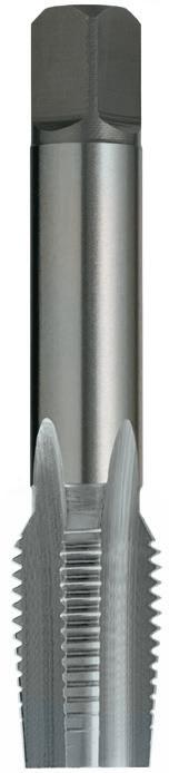
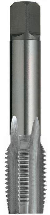
ISO Taps Pipe, G (BSPF), Spiral Point Gun
- General purpose use
- Suitable for materials up to 1000N/mm2
- Through & blind holes
- Depths up to approx. 1 x d1
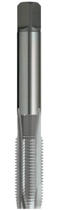
115 P Steel M Stainless Steel K Cast Iron N Non-Ferrous Metals S Titanium & Super Alloys H Hard Materials T484 T480 T479 VDI 3323 ISO • • • 1 P • • • 2 • • • 3 • • • 4 5 • • • 6 • • • 7 8 9 10 11 12 13 • 14.1 M • 14.2 14.3 • • 15 K 16 • • • 17 • 18 • • • 19 20 • • • 21 N • • • 22 • • • 23 • • • 24 25 • • • 26 • 27 • • 28 29 30 31 S 32 33 34 35 36 37.1 37.2 37.3 37.4 37.5 • Optimal • Effective 38.1 H 38.2 39.1 39.2 • 40 41 T484 0973 1/8 28 80 24 33 10 8 11 3 8.8 T484 0973 1316 1/4 19 95 30 - 11.2 9 12 3 11.8 T484 1316 1666 3/8 19 112 37 - 14 11.2 14 4 15.3 T484 1666 2096 1/2 14 118 38 - 16 12.5 16 4 19.0 T484 2096 2644 3/4 14 135 45 - 20 16 20 4 24.5 T484 2644 0973 1/8 28 59 15 - 8.0 6.3 9 4 8.8 T479 0973 T480 0973 1316 1/4 19 67 19 - 10.0 8.0 11 4 11.8 T479 1316 T480 1316 1666 3/8 19 75 21 - 12.5 10.0 13 4 15.3 T479 1666 T480 1666 2096 1/2 14 87 26 - 16.0 12.5 16 4 19.0 T479 2096 T480 2096 2291 5/8 14 91 26 - 18.0 14.0 18 4 21.0 T479 2291 T480 2291 2644 3/4 14 96 28 - 20.0 16.0 20 4 24.5 T479 2644 T480 2644 3020 7/8 14 102 29 - 22.4 18.0 22 4 28.5 T479 3020 T480 3020 3325 1 11 109 33 - 25.0 20.0 24 4 31.0 T479 3325 T480 3325 4191 1-1/4 11 119 36 - 31.5 25.0 28 4 39.5 T479 4191 T480 4191 4780 1-1/2 11 125 37 - 35.5 28.0 31 4 45.5 T479 4780 T480 4780 5375 1-3/4 11 132 39 - 35.5 28.0 31 6 51.5 T479 5375 T480 5375 5961 2 11 140 41 - 40.0 31.5 34 6 57.5 T479 5961 T480 5961 115 115
purpose use
up
1000N/mm2
materials
to
Catalogue Code T479 T480 Discount Group D0702 D0702 Material HSS HSS Surface Finish Brt Brt Sutton Designation N N Geometry -Chamfer Taper Intermediate Limit Z3 Z3 Size Ref. d1 TPI l1 l2 l3 d2 sq l4 z drill ø Item # Item #
Size Ref. d1 TPI l1 l2 l3 d2 sq l4 z drill ø Item # G (BSPF) Contents Index
-
-
ISO Taps Pipe, G (BSPF), Straight Flute
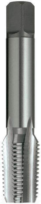
ISO Taps Pipe, G (BSPF), Spiral Flute
- Suitable for materials up to
- Through & blind holes
- Depths up to approx. 1 x d1
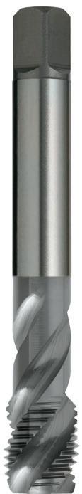
116 P Steel M Stainless Steel K Cast Iron N Non-Ferrous Metals S Titanium & Super Alloys H Hard Materials T909 T485 T481 VDI 3323 ISO • • • 1 P • • • 2 • • • 3 • • • 4 5 • • • 6 • • 7 8 9 10 11 12 13 • 14.1 M • 14.2 14.3 • • 15 K 16 • • • 17 • 18 • • 19 20 • • • 21 N • • • 22 • • • 23 • • • 24 25 • • • 26 • 27 • • • 28 29 30 31 S 32 33 34 35 36 37.1 37.2 37.3 37.4 37.5 • Optimal • Effective 38.1 H 38.2 39.1 39.2 • 40 41 116 0973 1/8 28 59 15 - 8.0 6.3 9 4 8.8 T481 0973 T909 0973 1316 1/4 19 67 19 - 10.0 8.0 11 4 11.8 T481 1316 T909 1316 1666 3/8 19 75 21 - 12.5 10.0 13 4 15.3 T481 1666 T909 1666 2096 1/2 14 87 26 - 16.0 12.5 16 4 19.0 T481 2096 T909 2096 2291 5/8 14 91 26 - 18.0 14.0 18 4 21.0 T481 2291 T909 2291 2644 3/4 14 96 28 - 20.0 16.0 20 4 24.5 T481 2644 T909 2644 3020 7/8 14 102 29 - 22.4 18.0 22 4 28.5 T481 3020 • 3325 1 11 109 33 - 25.0 20.0 24 4 31.0 T481 3325 T909 3325 4191 1-1/4 11 119 36 - 31.5 25.0 28 4 39.5 T481 4191 • 4780 1-1/2 11 125 37 - 35.5 28.0 31 4 45.5 T481 4780 • 5375 1-3/4 11 132 39 - 35.5 28.0 31 6 51.5 T481 5375 • 5961 2 11 140 41 - 40.0 31.5 34 6 57.5 T481 5961 • T485 0973 1/8 28 80 24 33 10 8 11 3 8.8 T485 0973 1316 1/4 19 95 30 - 11.2 9 12 3 11.8 T485 1316 1666 3/8 19 112 37 - 14 11.2 14 4 15.3 T485 1666 2096 1/2 14 118 38 - 16 12.5 16 4 19.0 T485 2096 2644 3/4 14 135 45 - 20 16 20 4 24.5 T485 2644 • Available on request as special manufacture. Subject to lead time. - General purpose use
Suitable for materials up to 1000N/mm2
Through & blind holes
-
-
Suitable for both hand and machine operations
Depths up to approx. 1 x d1
Catalogue Code T481 T909 Discount Group D0702 D0702 Material HSS HSS Surface Finish Brt Brt Sutton Designation N N Geometry -Chamfer Bottoming Set Limit Z3 Z3 Size Ref. d1 TPI l1 l2 l3 d2 sq l4 z drill ø Item # Item #
- General purpose use
1000N/mm2
Size Ref. d1 TPI l1 l2 l3 d2 sq l4 z drill ø Item # G (BSPF) Contents Index
- General purpose use
- Suitable for materials up to 1000N/mm2
- Through & blind holes
- Suitable for both hand and machine operations
- Depths up to approx. 1 x d1
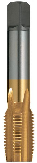
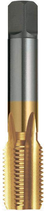
117 P Steel M Stainless Steel K Cast Iron N Non-Ferrous Metals S Titanium & Super Alloys H Hard Materials T483 T482 VDI 3323 ISO • • 1 P • • 2 • • 3 • • 4 • • 5 • • 6 • • 7 • • 8 9 • • 10 11 • • 12 13 • • 14.1 M 14.2 14.3 • • 15 K 16 • • 17 18 • • 19 20 • • 21 N • • 22 • • 23 • • 24 25 • • 26 • • 27 • • 28 29 30 31 S 32 33 34 35 36 37.1 37.2 37.3 37.4 37.5 • Optimal • Effective 38.1 H 38.2 39.1 39.2 40 41 0973 1/8 28 59 15 - 8.0 6.3 9 4 8.8 T482 0973 T483 0973 1316 1/4 19 67 19 - 10.0 8.0 11 4 11.8 T482 1316 T483 1316 1666 3/8 19 75 21 - 12.5 10.0 13 4 15.3 T482 1666 T483 1666 2096 1/2 14 87 26 - 16.0 12.5 16 4 19.0 T482 2096 T483 2096 2291 5/8 14 91 26 - 18.0 14.0 18 4 21.0 • T483 2291 2644 3/4 14 96 28 - 20.0 16.0 20 4 24.5 • T483 2644 3020 7/8 14 102 29 - 22.4 18.0 22 4 28.5 • • 3325 1 11 109 33 - 25.0 20.0 24 4 31.0 • • 4191 1-1/4 11 119 36 - 31.5 25.0 28 4 39.5 • • 4780 1-1/2 11 125 37 - 35.5 28.0 31 4 45.5 • • 5375 1-3/4 11 132 39 - 35.5 28.0 31 6 51.5 • • 5961 2 11 140 41 - 40.0 31.5 34 6 57.5 • • 117 • Available on request as special manufacture. Subject to lead time.
Pipe, G (BSPF), Straight Flute Catalogue Code T482 T483 Discount Group D0706 D0706 Material HSS HSS Surface Finish TiN TiN Sutton Designation N N Geometry -Chamfer Intermediate Bottoming Limit Z3 Z3 Size Ref. d1 TPI l1 l2 l3 d2 sq l4 z drill ø Item # Item # G (BSPF) Contents Index
ISO Taps
ISO Taps Pipe, Rc (BSPT), Straight Flute
- General purpose use
- Suitable for materials up to 1000N/mm2
- Through & blind holes
- Suitable for both hand and machine operations
- Taper pipe reamer recommended prior to tapping Rc (BSPT) thread forms
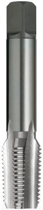
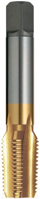
ISO Taps Pipe, Rp & Pg Series, Straight Flute
- General Purpose use for materials up to approx. 1000 N/mm2
- Through & blind holes
- Suitable for both hand and machine operations
Discount Group: D0702 Rc (BSPT) 1:16 Taper Rate
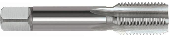
118 118 118 118 P Steel M Stainless Steel K Cast Iron N Non-Ferrous Metals S Titanium & Super Alloys H Hard Materials T477 / T478 T476 T475 VDI 3323 ISO • • • 1 P • • • 2 • • • 3 • • • 4 • 5 • • • 6 • • • 7 • 8 9 • 10 11 12 13 • 14.1 M 14.2 14.3 • • • 15 K 16 • • • 17 18 • • • 19 20 • • • 21 N • • • 22 • • • 23 • • • 24 25 • • • 26 • 27 • • • 28 29 30 31 S 32 33 34 35 36 37.1 37.2 37.3 37.4 37.5 • Optimal • Effective 38.1 H 38.2 39.1 39.2 40 41 0973 1/8 28 59 15 - 8.0 6.3 9 4 8.4 T475 0973 T476 0973 1316 1/4 19 67 19 - 10.0 8.0 11 4 10.8 T475 1316 T476 1316 1666 3/8 19 75 21 - 12.5 10.0 13 4 14.5 T475 1666 T476 1666 2096 1/2 14 87 26 - 16.0 12.5 16 4 18.0 T475 2096 T476 2096 2644 3/4 14 96 28 - 20.0 16.0 20 4 23.0 T475 2644 • 3325 1 11 109 33 - 25.0 20.0 24 5 29.0 T475 3325 • 4191 1-1/4 11 119 36 - 31.5 25.0 28 5 38.0 T475 4191 • 4780 1-1/2 11 125 37 - 35.5 28.0 31 7 44.0 T475 4780 • 5961 2 11 140 41 - 40.0 31.5 34 7 55.0 T475 5961 • T477 0973 1/8 28 59 15 - 8.0 6.3 9 4 8.6 - T477 0973 1316 1/4 19 67 19 - 10.0 8.0 11 4 11.5 - T477 1316 1666 3/8 19 75 21 - 12.5 10.0 13 4 15.0 - T477 1666 2096 1/2 14 87 26 - 16.0 12.5 16 4 18.5 - T477 2096 2644 3/4 14 96 28 - 20.0 16.0 20 4 24.0 - T477 2644 3325 1 11 109 33 - 25.0 20.0 24 4 30.2 - T477 3325 4191 1-1/4 11 119 36 - 31.5 25.0 28 4 39.0 - T477 4191 4780 1-1/2 11 125 37 - 35.5 28.0 31 4 45.0 - T477 4780 5961 2 11 140 41 - 40.0 31.5 34 4 56.4 - T477 5961 T478 1250 Pg 7 20 89 29 - 9 7.1 10 4 11.3 12.5 T478 1250 1520 Pg 9 18 102 32 - 12.5 10 12 4 13.9 15.2 T478 1520 1860 Pg 11 18 112 37 - 14 11.2 14 4 17.3 18.6 T478 1860 2040 Pg 13.5 18 118 38 - 16 12.5 16 4 19.1 20.4 T478 2040 2250 Pg 16 18 118 38 - 16 12.5 16 4 21.2 22.5 T478 2250 2830 Pg 21 16 138 48 - 20 16 20 4 26.8 28.3 T478 2830 • Available on request as special manufacture. Subject to lead time. *Nominal OD
Catalogue Code T475 T476 Discount Group D0702 D0706 Material HSS HSS Surface Finish Brt TiN Sutton Designation N N Geometry -Chamfer Bottoming Bottoming Limit & Nut Tolerance To Suit To Suit Size Ref. d1 TPI l1 l2 l3 d2 sq l4 z drill ø Item # Item #
Rp Series (BSPPL) Sealing Pipe Thread Parallel Pg – Steel Conduit (Armour Pipe)
Size Ref. d1 TPI l1 l2 l3 d2 sq l4 z drill ø Nom* OD Item # Rc, Rp, Pg Contents Index
ISO Taps Pipe, National Series
- General purpose use, materials up to approx. 1000 N/mm2
- Suitable for both hand and machine operations
- Taper pipe reamer recommended prior to tapping
(Dryseal Straight) NPT (National Pipe Taper) 15° Chamfer (1:16 Taper Rate)
NPTF (Dryseal Taper) 15° Chamfer (1:16 Taper Rate)
Reamers Taper Pipe (1:16)
- Used prior to tapping - For Rc (BSPT), NPT & NPTF tapered threads - Prolongs tap life, especially in tough materials
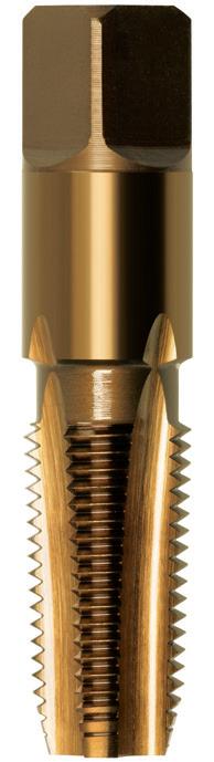
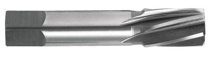
119 P Steel M Stainless Steel K Cast Iron N Non-Ferrous Metals S Titanium & Super Alloys H Hard Materials R108 T488 T487 T486 VDI 3323 ISO • • • • 1 P • • • • 2 • • • • 3 • • • • 4 • 5 • • • • 6 • • • • 7 • 8 9 • 10 11 • 12 13 • • • • 14.1 M • 14.2 • 14.3 • • • • 15 K • 16 • • • • 17 • 18 • • • • 19 • 20 • • • • 21 N • • • • 22 • • • • 23 • • • • 24 25 • • • • 26 • • • • 27 • • • • 28 29 30 31 S 32 33 34 35 36 37.1 37.2 37.3 37.4 37.5 • Optimal • Effective 38.1 H 38.2 39.1 39.2 • 40 41 1029 1/8 27 54 19 - 11.11 8.33 9.5 4 GH3 8.6 T486 1029 1372 1/4 18 62 27 - 14.29 10.70 11.1 4 GH4 11.3 T486 1372 1715 3/8 18 65 27 - 17.78 13.49 12.7 4 GH4 14.5 T486 1715 2134 1/2 14 79 35 - 17.46 13.08 15.9 4 GH5 18.0 T486 2134 T487 1029 1/8 27 54 19 - 11.11 8.33 9.5 4 - 8.2 T487 1029 1372 1/4 18 62 27 - 14.29 10.70 11.1 4 - 10.8 T487 1372 1715 3/8 18 65 27 - 17.78 13.49 12.7 4 - 14.0 T487 1715 2134 1/2 14 79 35 - 17.46 13.08 15.9 4 - 17.5 T487 2134 2667 3/4 14 82 35 - 23.00 17.25 17.5 4 - 23.0 T487 2667 3340 1 11-1/2 95 44.5 - 28.60 21.40 20.6 5 - 28.5 T487 3340 4216 1-1/4 11-1/2 102 44.5 - 33.30 25.00 23.8 5 - 37.0 T487 4216 T488 1029 1/8 27 54 19 - 11.11 8.33 9.5 4 - 8.2 T488 1029 1372 1/4 18 62 27 - 14.29 10.70 11.1 4 - 10.8 T488 1372 1715 3/8 18 65 27 - 17.78 13.49 12.7 4 - 14.0 T488 1715 2134 1/2 14 79 35 - 17.46 13.08 15.9 4 - 17.50 T488 2134 R108 0803 1/8 0.316 2-11/32 19/32 0.353 0.315 6 R108 0803 1031 1/4 0.406 2-21/32 25/32 0.453 0.394 6 R108 1031 1372 3/8 0.540 2-31/32 7/8 0.592 0.492 6 R108 1372 1689 1/2 0.665 3-7/16 1-1/32 0.729 0.630 6 R108 1689 2225 3/4 0.876 3-25/32 1-1/8 0.945 0.787 6 R108 2225 2802 1 1.103 4-5/16 1-5/16 1.184 0.984 6 R108 2802 3668 1-1/4 1.444 4-11/16 1-7/16 1.529 1.240 6 R108 3668 4277 1-1/2 1.684 4-15/16 1-15/32 1.775 1.398 8 R108 4277 5484 2 2.159 5-17/32 1-5/8 2.260 1.575 8 R108 5484 Catalogue Code T486 Discount Group D0702 Material HSS Surface Finish Colour Temp Sutton Designation N GeometryChamfer Bottoming Limit & Nut Tolerance Refer Limit Size Ref. d1 TPI l1 l2 l3 d2 sq l4 z Limit drill ø Item #
Discount Group: B0302 NPSF
Size Ref. Size d1 l1 l2 d3 d2 z Item #
d2 d3 NPT Contents Index
120 Contents Index
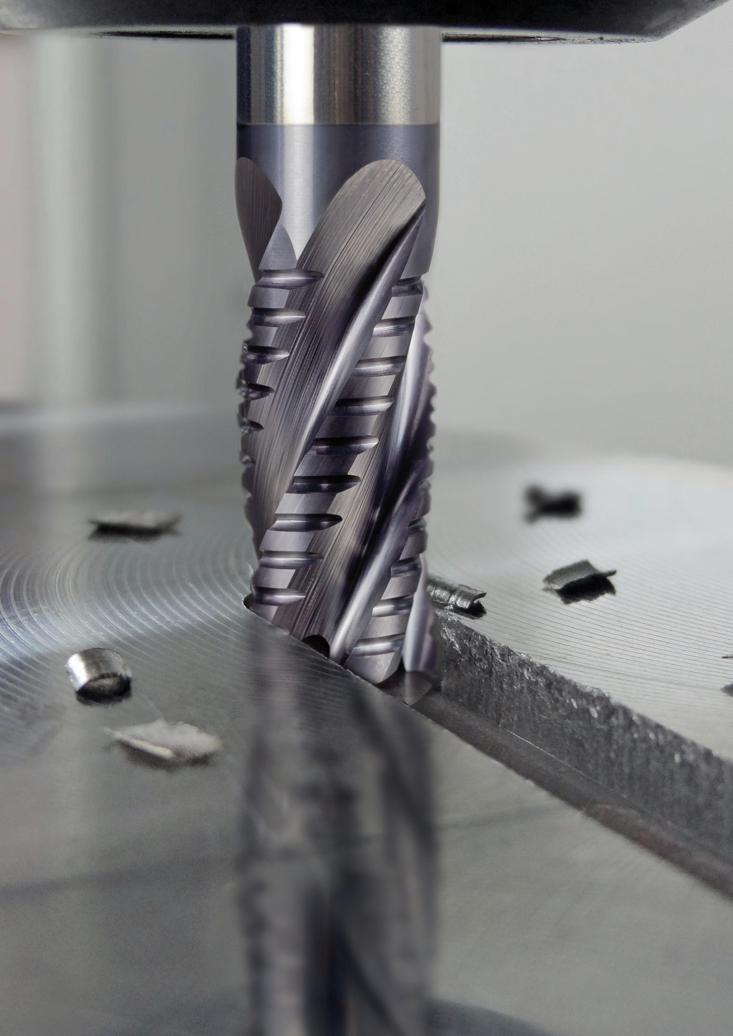
HSS ENDMILLS
• Slotting, Finishing, Roughing & Profiling • Short & Long Series
• General purpose & application specific geometries
recommendations, go to: www.suttonhps.com
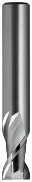
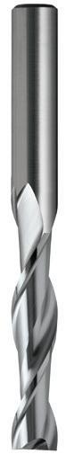
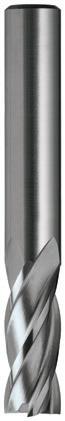
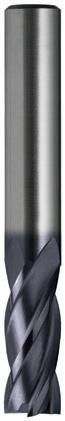
122 HSS Endmills Finder • Optimal • Effective Page 124 125 127 128 129 131 Catalogue Code E178 E100 E102 / E225 E184 E125 / E227 E192 Type of Cut: Slotting • • • • Finishing • • Universal • • Roughing • Profiling Material HSS HSS Co.8 HSS Co.8 HSS Co.8 HSS Co.8 HSS Co.8 Surface Finish Brt Brt Brt TiAlN Brt TiAlN Sutton Designation N N N N N N Standard Sutton Std JIS JIS DIN 844L JIS DIN 844K Shank Tolerance h6 h6 h6 h6 h6 h6 ISO VDI^ 3323 Material Condition HB N/mm2 P 1 Steel - Non-alloy, cast & free cutting ~ 0.15 %C A 125 440 • • • • • • 2 ~ 0.45 %C A 190 640 • • • • • • 3 QT 250 840 • • • • • • 4 ~ 0.75 %C A 270 910 • • • • • • 5 QT 300 1010 • • • • • 6 Steel - Low alloy & cast < 5% of alloying elements A 180 610 • • • • • • 7 QT 275 930 • • • • • • 8 QT 300 1010 • • • • • 9 QT 350 1180 • 10 Steel - High alloy, cast & tool A 200 680 • • • • • 11 HT 325 1100 • 12 Steel - Corrosion resistant & cast Ferritic / Martensitic A 200 680 • • • 13 Martensitic QT 240 810 • • • • • M 14.1 Stainless Steel Austenitic AH 180 610 • • 14.2 Duplex 250 840 • • 14.3 Precipitation Hardening 250 840 • K 15 Cast Iron - Grey (GG) Ferritic / Pearlitic 180 610 • • • • • • 16 Pearlitic 260 880 • • • • • 17 Cast Iron - Nodular (GGG) Ferritic 160 570 • • • • • • 18 Pearlitic 250 840 • • • • • 19 Cast Iron - Malleable Ferritic 130 460 • • • • • • 20 Pearlitic 230 780 • • • • • N 21 Aluminum & Magnesium - wrought alloy Non Heat Treatable 60 210 • • • • • • 22 Heat Treatable AH 100 360 • • • • • • 23 Aluminum & Magnesium - cast alloy ≤12% Si Non Heat Treatable 75 270 • • • • • • 24 Heat Treatable AH 90 320 • • • • • • 25 Al & Mg - cast alloy >12% Si Non Heat Treatable 130 460 • • • • 26 Copper & Cu alloys (Brass/Bronze) Free cutting, Pb > 1% 110 390 • • • • • 27 Brass (CuZn, CuSnZn) 90 320 28 Bronze (CuSn) 100 360 • • • • • 29 Non-metallic - Thermosetting & fiber-reinforced plastics 30 Non-metallic - Hard rubber, wood etc. S 31 High temp. alloys Fe based A 200 680 32 AH 280 950 33 Ni / Co based A 250 840 34 AH 350 1180 35 C 320 1080 36 Titanium & Ti alloys CP Titanium 400 MPa 37.1 Alpha alloys 860 MPa 37.2 Alpha / Beta alloys A 960 MPa 37.3 AH 1170 MPa 37.4 Beta alloys A 830 MPa 37.5 AH 1400 MPa H 38.1 Hardened steel HT 45 HRC 38.2 HT 55 HRC 39.1 HT 58 HRC 39.2 HT 62 HRC 40 Cast Iron Chilled C 400 1350 • 41 HT 55 HRC Condition: A (Annealed), AH (Age Hardened), C (Cast), HT (Hardened & Tempered), QT (Quenched & Tempered) ISO VDI Material Group Sutton P A Steel N UNI M R Stainless Steel VA K F Cast Iron GG N N Non-Ferrous Metals, Aluminiums & Coppers AI W S S Titaniums & Super Alloys Ti Ni H H Hard Materials (≥ 45 HRC) H ^ VDI 3323 material groups can also be determined
material
back of this catalogue. For expert tooling
Section Finder Contents Index
by referring to the
cross reference listing in the application guide at the

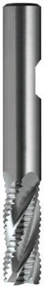
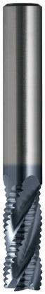
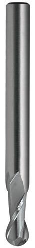
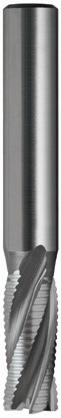
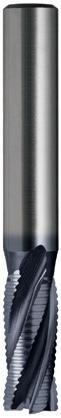
Slotting
Finishing
Universal
Roughing
Profiling
123 132 133 134 135 136 137 138 138 E127 / E229 E230 E142 / E144 E143 E146 E113 E168 E169
• •
• •
• • • • •
•
HSS Co.8 HSS Co.8 HSS Co.8 HSS Co.8 HSS Co.8 Brt TiCN Brt TiCN Brt Brt Brt TiCN N WN WN N NH JIS JIS DIN 844L Sutton Std JIS h6 h6 h6 h6 h6 VDI^ 3323 ISO • • • • • • 1 P • • • • • • 2 • • • • • • • 3 • • • • • • 4 • • • • • • 5 • • • • • • 6 • • • • • • 7 • • • • • • 8 • • • 9 • • • • • 10 • • • 11 • • • • 12 • • • • 13 • • • 14.1 M • • • 14.2 • • 14.3 • • • • • • 15 K • • • • 16 • • • • • • 17 • • • • 18 • • • • • • 19 • • • • 20 • • • • • • 21 N • • • • • • 22 • • • • • • 23 • • • • • • 24 • • 25 • • • • • • 26 • • 27 • • • • • • 28 29 30 31 S 32 33 34 35 36 37.1 37.2 37.3 37.4 37.5 38.1 H 38.2 39.1 39.2 • • 40 41 Section Finder Contents Index
Roughers Woodruff Cutter,
- For cutting key seats to suit standard imperial woodruff keys
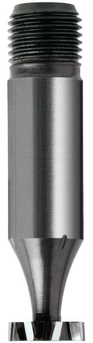
Catalogue Code E178
Discount Group B0709
Material HSS
Surface Finish Brt
Sutton Designation General Purpose
124 124 P Steel M Stainless Steel K Cast Iron N Non-Ferrous Metals S Titanium & Super Alloys H Hard Materials E178 VDI 3323 ISO • 1 P • 2 • 3 • 4 5 • 6 • 7 8 9 10 11 12 13 14.1 M 14.2 14.3 • 15 K 16 • 17 18 • 19 20 • 21 N • 22 • 23 • 24 25 26 27 28 29 30 31 S 32 33 34 35 36 37.1 37.2 37.3 37.4 37.5 • Optimal • Effective 38.1 H 38.2 39.1 39.2 40 41 0204 204 1/2 1/16 2 1/2 E178 0204 0304 304 1/2 3/32 2 1/2 E178 0304 0305 305 5/8 3/32 2 1/2 E178 0305 0404 404 1/2 1/8 2 1/2 E178 0404 0405 405 5/8 1/8 2 1/2 E178 0405 0406 406 3/4 1/8 2-1/4 1/2 E178 0406 0505 505 5/8 5/32 2 1/2 E178 0505 0506 506 3/4 5/32 2-1/4 1/2 E178 0506 0507 507 7/8 5/32 2-1/2 1/2 E178 0507 0606 606 3/4 3/16 2-1/4 1/2 E178 0606 0607 607 7/8 3/16 2-1/2 1/2 E178 0607 0608 608 1 3/16 2-3/4 1/2 E178 0608 0609 609 1-1/8 3/16 2-3/4 1/2 E178 0609 0807 807 7/8 1/4 2-1/2 1/2 E178 0807 0808 808 1 1/4 2-3/4 1/2 E178 0808 0809 809 1-1/8 1/4 2-3/4 1/2 E178 0809 0810 810 1-1/4 1/4 2-3/4 1/2 E178 0810 0812 812 1-1/2 1/4 3 1/2 E178 0812 1008 1008 1 5/16 2-3/4 1/2 E178 1008 1009 1009 1-1/8 5/16 2-3/4 1/2 E178 1009 1010 1010 1-1/4 5/16 2-3/4 1/2 E178 1010 1011 1011 1-3/8 5/16 3 1/2 E178 1011 1012 1012 1-1/2 5/16 3 1/2 E178 1012 1210 1210 1-1/4 3/8 2-3/4 1/2 E178 1210 1211 1211 1-3/8 3/8 3 1/2 E178 1211 1212 1212 1-1/2 3/8 3 1/2 E178 1212
Form
Size Ref. BS Cutter & Key # d1 l2 l1 d2 Item #
GeometryShank
(DIN 1835) D Shank Tolerance h6
Threaded D Section Finder Contents Index
-
Slot Drills 2 Flute, R30 N, Regular
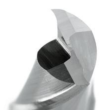
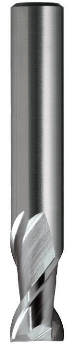
Catalogue Code E100
Discount Group B0502 Material HSS Co.8
Surface Finish Brt
Sutton Designation N Geometry R30 Shank Form (DIN 1835) A Shank Tolerance h6
125 125 0100 1 50 3 6 2 E100 0100 0150 1.5 50 4.5 6 2 E100 0150 0200 2 50 7 6 2 E100 0200 0250 2.5 50 7 6 2 E100 0250 0300 3 50 9 6 2 E100 0300 0350 3.5 60 12 8 2 E100 0350 0400 4 60 12 8 2 E100 0400 0450 4.5 60 15 8 2 E100 0450 0500 5 60 15 8 2 E100 0500 0550 5.5 60 15 8 2 E100 0550 0600 6 60 15 8 2 E100 0600 0650 6.5 65 20 10 2 E100 0650 0700 7 65 20 10 2 E100 0700 0750 7.5 65 20 10 2 E100 0750 0800 8 65 20 10 2 E100 0800 0850 8.5 75 25 10 2 E100 0850 0900 9 75 25 10 2 E100 0900 0950 9.5 75 25 10 2 E100 0950 1000 10 75 25 10 2 E100 1000 1100 11 80 30 12 2 E100 1100 1200 12 80 30 12 2 E100 1200 1300 13 90 35 16 2 E100 1300 1400 14 90 35 16 2 E100 1400 1500 15 95 40 16 2 E100 1500 1600 16 95 40 16 2 E100 1600 1700 17 105 40 20 2 E100 1700 1800 18 105 40 20 2 E100 1800 1900 19 110 45 20 2 E100 1900 2000 20 110 45 20 2 E100 2000 2100 21 110 45 20 2 E100 2100 2200 22 110 45 20 2 E100 2200 2400 24 120 50 25 2 E100 2400 2500 25 120 50 25 2 E100 2500 2800 28 125 55 25 2 E100 2800 3000 30 125 55 25 2 E100 3000 3200 32 145 60 32 2 E100 3200 P Steel M Stainless Steel K Cast Iron N Non-Ferrous Metals S Titanium & Super Alloys H Hard Materials E100 VDI 3323 ISO • 1 P • 2 • 3 • 4 • 5 • 6 • 7 • 8 9 • 10 11 12 • 13 14.1 M 14.2 14.3 • 15 K • 16 • 17 • 18 • 19 • 20 • 21 N • 22 • 23 • 24 • 25 • 26 27 • 28 29 30 31 S 32 33 34 35 36 37.1 37.2 37.3 37.4 37.5 • Optimal • Effective 38.1 H 38.2 39.1 39.2 40 41
precision
- For
milling of slots & cavities
Suitable
materials
to 1000
for
up
N/mm2
non-ferrous
- For soft steels &
material
Size Ref. d1 (e8) l1 l2 d2 z Item #
Vc Page #: 206 Section Finder Contents Index
Slot Drills 2 Flute, R30 N, Regular
- For precision milling of slots & cavities
- Suitable for materials up to 1000 N/mm2
- For soft steels & non-ferrous material
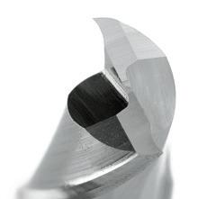
Catalogue Code E100
Discount Group B0502
Material HSS Co.8
Surface Finish Brt
Sutton Designation N
Geometry R30
Shank Form (DIN 1835) A Shank Tolerance h6
126 0159 1/16 1-31/32 1/8 1/4 2 E100 0159 0238 3/32 1-31/32 3/16 1/4 2 E100 0238 0318 1/8 1-31/32 7/32 1/4 2 E100 0318 0476 3/16 2-3/8 3/8 1/4 2 E100 0476 0635 1/4 2-9/16 9/16 1/4 2 E100 0635 0794 5/16 2-9/16 9/16 3/8 2 E100 0794 0953 3/8 2-3/4 23/32 3/8 2 E100 0953 1270 1/2 3-17/32 1 1/2 2 E100 1270 1588 5/8 3-3/4 1-3/16 5/8 2 E100 1588 1905 3/4 4-5/16 1-9/16 3/4 2 E100 1905 2540 1 4-23/32 2 3/4 2 E100 2540 P Steel M Stainless Steel K Cast Iron N Non-Ferrous Metals S Titanium & Super Alloys H Hard Materials E100 VDI 3323 ISO • 1 P • 2 • 3 • 4 • 5 • 6 • 7 • 8 9 • 10 11 12 • 13 14.1 M 14.2 14.3 • 15 K • 16 • 17 • 18 • 19 • 20 • 21 N • 22 • 23 • 24 • 25 • 26 27 • 28 29 30 31 S 32 33 34 35 36 37.1 37.2 37.3 37.4 37.5 • Optimal • Effective 38.1 H 38.2 39.1 39.2 40 41
Size Ref. d1 (e8) l1 l2 d2 z Item #
Page #: 206 Section Finder Contents Index
Vc
Slot Drills 2 Flute, R30 N, Long
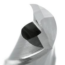
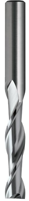
127 127 0300 3.0 60 15 6 2 E102 0300 0350 3.5 60 20 6 2 E102 0350 0400 4.0 60 20 6 2 E225 0400 0400 4.0 60 20 8 2 E102 0400 0450 4.5 60 25 6 2 E102 0450 0500 5.0 65 25 6 2 E225 0500 0500 5.0 65 25 8 2 E102 0500 0550 5.5 65 25 6 2 E102 0550 0600 6.0 65 25 6 2 E225 0600 0600 6.0 65 25 8 2 E102 0600 0650 6.5 80 35 10 2 E102 0650 0700 7.0 80 35 10 2 E102 0700 0750 7.5 80 35 10 2 E102 0750 0800 8.0 80 35 10 2 E102 0800 0850 8.5 95 45 10 2 E102 0850 0900 9.0 95 45 10 2 E102 0900 0950 9.5 95 45 10 2 E102 0950 1000 10.0 95 45 10 2 E102 1000 1100 11.0 105 55 12 2 E102 1100 1200 12.0 105 55 12 2 E102 1200 1400 14.0 110 55 16 2 E102 1400 1600 16.0 120 65 16 2 E102 1600 1800 18.0 130 65 20 2 E102 1800 2000 20.0 140 75 20 2 E102 2000 2200 22.0 140 75 20 2 E102 2200 2400 24.0 160 90 25 2 E102 2400 2500 25.0 160 90 25 2 E102 2500 Sutton Standard 0635 1/4 2-9/16 1 1/4 2 E102 0635 0953 3/8 3-3/4 1-3/4 3/8 2 E102 0953 1270 1/2 4-5/16 2-5/32 1/2 2 E102 1270 1905 3/4 5-1/2 2-61/64 3/4 2 E102 1905 P Steel M Stainless Steel K Cast Iron N Non-Ferrous Metals S Titanium & Super Alloys H Hard Materials E225 E102 VDI 3323 ISO • • 1 P • • 2 • • 3 • • 4 • • 5 • • 6 • • 7 • • 8 9 • • 10 11 12 13 14.1 M 14.2 14.3 15 K 16 • • 17 18 19 20 • • 21 N • • 22 • • 23 • • 24 25 • • 26 27 • • 28 29 30 31 S 32 33 34 35 36 37.1 37.2 37.3 37.4 37.5 • Optimal • Effective 38.1 H 38.2 39.1 39.2 40 41 - For long-reach slotting applications - Suitable for materials up to 1000 N/mm2 - For soft steels & non-ferrous material
Catalogue Code E102 E225 Discount Group B0502 B0502 Material HSS Co.8 HSS Co.8 Surface Finish Brt Brt Sutton Designation N N Geometry R30 R30 Shank Form (DIN 1835) A A Shank Tolerance h6 h6 Size Ref. d1 (e8) l1 l2 d2 z Item # Item # Vc Page #: 206 Section Finder Contents Index
Slot Drills 2 Flute, R30 N, Long
- For long-reach slotting applications
- Suitable for materials up to 1000 N/mm2
- For soft steels & non-ferrous material
- TiAlN for longer tool life
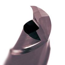

Catalogue Code E184
Discount Group B0608
Material HSS Co.8
Surface Finish TiAlN
Sutton Designation N
Geometry R30
Shank Form (DIN 1835) A Shank Tolerance h6
E184
128 128 P Steel M Stainless Steel K Cast Iron N Non-Ferrous Metals S Titanium & Super Alloys H Hard Materials E184 VDI 3323 ISO • 1 P • 2 • 3 • 4 • 5 • 6 • 7 • 8 • 9 • 10 • 11 • 12 • 13 • 14.1 M • 14.2 • 14.3 • 15 K 16 • 17 18 19 20 • 21 N • 22 • 23 • 24 • 25 • 26 27 • 28 29 30 31 S 32 33 34 35 36 37.1 37.2 37.3 37.4 37.5 • Optimal • Effective 38.1 H 38.2 39.1 39.2 40 41 0300 3.0 56 12 6 2 E184 0300 0350 3.5 59 15 6 2 E184 0350 0400 4.0 63 19 6 2 E184 0400 0500 5.0 68 24 6 2 E184 0500 0600
68 24 6 2
8.0 88 38 10 2
6.0
E184 0600 0800
0800 1000 10.0 95 45 10 2 E184 1000 1200 12.0 110 53 12 2 E184 1200 1400 14.0 110 53 12 2 E184 1400 1600 16.0 123 63 16 2 E184 1600 1800 18.0 123 63 16 2 E184 1800 2000 20.0 141 75 20 2 E184 2000
Size Ref. d1 (e8) l1 l2 d2 z Item # Vc
#: 206 Section Finder Contents Index
Page
- For precision finish milling applications
- Suitable for materials up to 1000 N/mm2
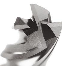
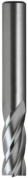
129 129 129 P Steel M Stainless Steel K Cast Iron N Non-Ferrous Metals S Titanium & Super Alloys H Hard Materials E227 E125 VDI 3323 ISO • • 1 P • • 2 • • 3 • • 4 • • 5 • • 6 • • 7 • • 8 9 • • 10 11 • • 12 • • 13 14.1 M 14.2 14.3 • • 15 K • • 16 • • 17 • • 18 • • 19 • • 20 • • 21 N • • 22 • • 23 • • 24 25 • • 26 27 • • 28 29 30 31 S 32 33 34 35 36 37.1 37.2 37.3 37.4 37.5 • Optimal • Effective 38.1 H 38.2 39.1 39.2 40 41 0150 1.5 50 3 6 4 E125 0150 0200 2.0 50 6 6 4 E125 0200 0250 2.5 50 7 6 4 E125 0250 0300 3.0 50 9 6 4 E125 0300 0350 3.5 60 12 6 4 E227 0350 0350 3.5 60 12 8 4 E125 0350 0400 4.0 60 12 6 4 E227 0400 0400 4.0 60 12 8 4 E125 0400 0450 4.5 60 15 6 4 E227 0450 0450 4.5 60 15 8 4 E125 0450 0500 5.0 60 15 6 4 E227 0500 0500 5.0 60 15 8 4 E125 0500 0550 5.5 60 15 6 4 E227 0550 0550 5.5 60 15 8 4 E125 0550 0600 6.0 60 15 6 4 E227 0600 0600 6.0 60 15 8 4 E125 0600 0650 6.5 65 20 10 4 E125 0650 0700 7.0 65 20 10 4 E125 0700 0750 7.5 65 20 10 4 E125 0750 0800 8.0 65 20 10 4 E125 0800 0850 8.5 75 25 10 4 E125 0850 0900 9.0 75 25 10 4 E125 0900 0950 9.5 75 25 10 4 E125 0950 1000 10.0 75 25 10 4 E125 1000 1050 10.5 80 30 12 4 E125 1050 1100 11.0 80 30 12 4 E125 1100 1150 11.5 80 30 12 4 E125 1150 1200 12.0 80 30 12 4 E125 1200 1300 13.0 90 35 16 4 E125 1300 1400 14.0 90 35 16 4 E125 1400 1500 15.0 95 40 16 4 E125 1500 1600 16.0 95 40 16 4 E125 1600 1700 17.0 105 40 20 4 E125 1700 1800 18.0 105 40 20 4 E125 1800 1900 19.0 110 45 20 4 E125 1900 2000 20.0 110 45 20 4 E125 2000 2200 22.0 110 45 20 4 E125 2200 2400 24.0 120 50 25 4 E125 2400 2500 25.0 120 50 25 4 E125 2500 2600 26.0 120 50 25 4 E125 2600 2800 28.0 125 55 25 6 E125 2800 3000 30.0 125 55 25 6 E125 3000 3200 32.0 145 60 32 6 E125 3200
Catalogue Code E125 E227 Discount Group B0502 B0502 Material HSS Co.8 HSS Co.8 Surface Finish Brt Brt Sutton Designation N N Geometry R30 R30 Shank Form (DIN 1835) A A Shank Tolerance h6 h6 Size Ref. d1 (k9) l1 l2 d2 z Item # Item # Vc Page #: 206 Section Finder Contents Index
Endmills 4 Flute, R30 N, Regular
Endmills 4 Flute, R30 N, Regular
- For precision finish milling applications
- Suitable for materials up to 1000 N/mm2
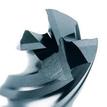
Catalogue Code E125
Discount Group B0502
Material HSS Co.8
Surface Finish Brt
Sutton Designation N Geometry R30
Shank Form (DIN 1835) A Shank Tolerance h6
130 P Steel M Stainless Steel K Cast Iron N Non-Ferrous Metals S Titanium & Super Alloys H Hard Materials E125 VDI 3323 ISO • 1 P • 2 • 3 • 4 • 5 • 6 • 7 • 8 9 • 10 11 • 12 • 13 14.1 M 14.2 14.3 • 15 K • 16 • 17 • 18 • 19 • 20 • 21 N • 22 • 23 • 24 25 • 26 27 • 28 29 30 31 S 32 33 34 35 36 37.1 37.2 37.3 37.4 37.5 • Optimal • Effective 38.1 H 38.2 39.1 39.2 40 41 0159 1/16 1-31/32 1/4 1/4 4 E125 0159 0238 3/32 1-31/32 9/32 1/4 4 E125 0238 0318 1/8 1-31/32 11/32 1/4 4 E125 0318 0476 3/16 2-11/32 19/32 1/4 4 E125 0476 0635 1/4 2-11/32 19/32 1/4 4 E125 0635 0794 5/16 2-9/16 25/32 3/8 4 E125 0794 0953 3/8 2-15/16 31/32 3/8 4 E125 0953 1270 1/2 3-7/32 1-3/8 1/2 4 E125 1270 1588 5/8 3-3/4 1-9/16 5/8 4 E125 1588 1905 3/4 4-5/16 1-3/4 3/4 4 E125 1905 2223 7/8 4-5/16 1-3/4 3/4 4 E125 2223 2540 1 4-23/32 1-31/32 3/4 4 E125 2540 2541 1 4-23/32 1-31/32 1 4 E125 2541
Size Ref. d1 (k9) l1 l2 d2 z Item # Vc
206 Section Finder Contents Index
Page #:
Endmills 4 Flute, R30 N, Regular
- For precision finish milling applications
- Suitable for materials up to 1000 N/mm2
- TiAlN for longer tool life
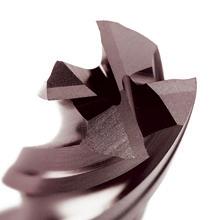
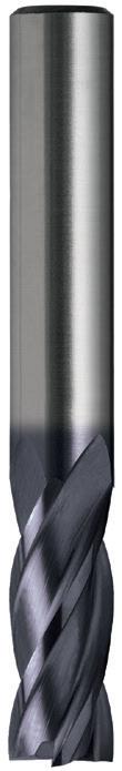
131 131 P Steel M Stainless Steel K Cast Iron N Non-Ferrous Metals S Titanium & Super Alloys H Hard Materials E192 VDI 3323 ISO • 1 P • 2 • 3 • 4 • 5 • 6 • 7 • 8 • 9 • 10 • 11 • 12 • 13 • 14.1 M • 14.2 • 14.3 • 15 K • 16 • 17 • 18 • 19 • 20 • 21 N • 22 • 23 • 24 • 25 • 26 27 • 28 29 30 31 S 32 33 34 35 36 37.1 37.2 37.3 37.4 37.5 • Optimal • Effective 38.1 H 38.2 39.1 39.2 • 40 41 0200 2.0 51 7 6 4 E192 0200 0250 2.5 52 8 6 4 E192 0250 0300 3.0 52 8 6 4 E192 0300 0400 4.0 55 11 6 4 E192 0400 0500 5.0 57 13 6 4 E192 0500 0600 6.0 57 13 6 4 E192 0600 0700 7.0 66 16 10 4 E192 0700 0800 8.0 69 19 10 4 E192 0800 0900 9.0 69 19 10 4 E192 0900 1000 10.0 72 22 10 4 E192 1000 1100 11.0 79 22 12 4 E192 1100 1200 12.0 83 26 12 4 E192 1200 1300 13.0 83 26 12 4 E192 1300 1400 14.0 83 26 12 4 E192 1400 1500 15.0 83 26 12 4 E192 1500 1600 16.0 92 32 16 4 E192 1600 1700 17.0 92 32 16 4 E192 1700 1800 18.0 92 32 16 4 E192 1800 2000 20.0 104 38 20 4 E192 2000 2200 22.0 121 45 20 6 E192 2200
Catalogue Code E192
TiAlN
N Geometry R30 Shank Form (DIN 1835) A Shank Tolerance h6 Size Ref. d1 (k9) l1 l2 d2 z Item # Vc Page #: 207 Section Finder Contents Index
Discount Group B0608 Material HSS Co.8 Surface Finish
Sutton Designation
For precision finish milling applications
Suitable for materials up to 1000 N/mm2
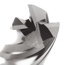
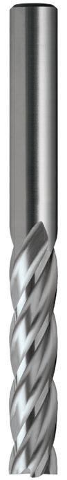
132 132 0200 2.0 60 10 6 4 E127 0200 0250 2.5 60 15 6 4 E127 0250 0300 3.0 60 15 6 4 E127 0300 0350 3.5 60 20 6 4 E229 0350 0400 4.0 60 20 6 4 E229 0400 0400 4.0 60 20 8 4 E127 0400 0450 4.5 65 25 6 4 E229 0450 0500 5.0 65 25 6 4 E229 0500 0500 5.0 65 25 8 4 E127 0500 0550 5.5 65 25 6 4 E229 0550 0600 6.0 65 25 6 4 E229 0600 0600 6.0 65 25 8 4 E127 0600 0650 6.5 80 35 10 4 E127 0650 0700 7.0 80 35 10 4 E127 0700 0750 7.5 80 35 10 4 E127 0750 0800 8.0 80 35 10 4 E127 0800 0900 9.0 95 45 10 4 E127 0900 0950 9.5 95 45 10 4 E127 0950 1000 10.0 95 45 10 4 E127 1000 1100 11.0 105 55 12 4 E127 1100 1200 12.0 105 55 12 4 E127 1200 1400 14.0 110 55 16 4 E127 1400 1600 16.0 120 65 16 4 E127 1600 1800 18.0 130 65 20 4 E127 1800 2000 20.0 140 75 20 4 E127 2000 2200 22.0 140 75 20 4 E127 2200 2400 24.0 160 90 25 4 E127 2400 2500 25.0 160 90 25 4 E127 2500 3200 32.0 190 105 32 6 E127 3200 0159 1/16 2-3/8 3/8 1/4 4 E127 0159 0318 1/8 2-3/8 19/32 1/4 4 E127 0318 0476 3/16 2-9/16 31/32 1/4 4 E127 0476 0635 1/4 2-9/16 31/32 1/4 4 E127 0635 0794 5/16 3-5/32 1-3/8 3/8 4 E127 0794 0953 3/8 3-3/4 1-25/32 3/8 4 E127 0953 1270 1/2 4-5/16 2-5/32 1/2 4 E127 1270 1588 5/8 4-23/32 2-9/16 5/8 4 E127 1588 1905 3/4 5-1/2 2-15/16 3/4 4 E127 1905 2540 1 6-5/16 3-17/32 3/4 4 E127 2540 P Steel M Stainless Steel K Cast Iron N Non-Ferrous Metals S Titanium & Super Alloys H Hard Materials E229 E127 VDI 3323 ISO • • 1 P • • 2 • • 3 • • 4 • • 5 • • 6 • • 7 • • 8 9 • • 10 11 • • 12 • • 13 14.1 M 14.2 14.3 • • 15 K • • 16 • • 17 • • 18 • • 19 • • 20 • • 21 N • • 22 • • 23 • • 24 25 • • 26 27 • • 28 29 30 31 S 32 33 34 35 36 37.1 37.2 37.3 37.4 37.5 • Optimal • Effective 38.1 H 38.2 39.1 39.2 40 41 • Available on request as special manufacture. Subject to lead time. -
-
Long Catalogue Code E127 E229 Discount Group B0502 B0502 Material HSS Co.8 HSS Co.8 Surface Finish Brt Brt Sutton Designation N N Geometry R30 R30 Shank Form (DIN 1835) A A Shank Tolerance h6 h6 Size Ref. d1 (k10) l1 l2 d2 z Item # Item # Section Finder Contents Index
Endmills 4 Flute, R30 N,
Endmills 4 Flute, R30 N, Long
- For precision finish milling applications - Suitable for materials up to 1000 N/mm2 - TiCN for longer tool life
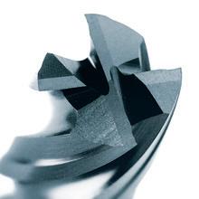
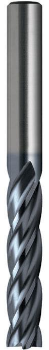
133 0400 4.0 60 20 6 4 E230 0400 0500 5.0 65 25 6 4 E230 0500 0600 6.0 65 25 6 4 E230 0600 P Steel M Stainless Steel K Cast Iron N Non-Ferrous Metals S Titanium & Super Alloys H Hard Materials E230 VDI 3323 ISO • 1 P • 2 • 3 • 4 • 5 • 6 • 7 • 8 • 9 • 10 • 11 • 12 • 13 • 14.1 M • 14.2 • 14.3 • 15 K • 16 • 17 • 18 • 19 • 20 • 21 N • 22 • 23 • 24 • 25 • 26 27 • 28 29 30 31 S 32 33 34 35 36 37.1 37.2 37.3 37.4 37.5 • Optimal • Effective 38.1 H 38.2 39.1 39.2 • 40 41
Code E230
Group B0516 Material HSS Co.8 Surface Finish TiCN
Designation N Geometry R30 Shank Form (DIN 1835) A Shank Tolerance h6 Size Ref. d1 (k10) l1 l2 d2 z Item # 133 Section Finder Contents Index
Catalogue
Discount
Sutton
- For roughing applications - NR geometry allows for heavy cuts - Suitable for materials up to 1000 N/mm2
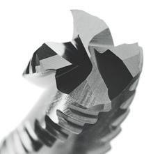
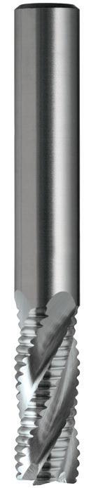
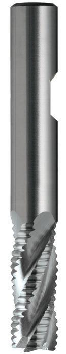
134 134 P Steel M Stainless Steel K Cast Iron N Non-Ferrous Metals S Titanium & Super Alloys H Hard Materials E144 E142 VDI 3323 ISO • • 1 P • • 2 • • 3 • • 4 5 • • 6 7 8 9 10 11 12 13 14.1 M 14.2 14.3 15 K 16 17 18 19 20 • • 21 N • • 22 • • 23 • • 24 25 • • 26 27 • • 28 29 30 31 S 32 33 34 35 36 37.1 37.2 37.3 37.4 37.5 • Optimal • Effective 38.1 H 38.2 39.1 39.2 40 41 0600 6.0 60 15 10 3 E142 0600 0800 8.0 65 20 10 3 E142 0800 1000 10.0 75 25 10 4 E142 1000 1200 12.0 80 30 12 4 E142 1200 1400 14.0 90 35 16 4 E142 1400 1500 15.0 95 40 16 4 E142 1500 1600 16.0 95 40 16 4 E144 1600 2000 20.0 110 45 20 4 E144 2000 2500 25.0 120 50 25 5 E144 2500 3000 30.0 125 55 25 6 E144 3000
Catalogue Code E142 E144 Discount Group B0402 B0402 Material HSS Co.8 HSS Co.8 Surface Finish Brt Brt Sutton Designation WN WN Geometry R30 NR R30 NR Shank Form (DIN 1835) A B Shank Tolerance h6 h6 Size Ref. d1 (js14) l1 l2 d2 z Item # Item #
NR (normal), R30 WN, Regular 45º NR B Section Finder Contents Index
Roughers
- For roughing applications - NR geometry allows for heavy cuts
- Suitable for materials up to 1000 N/mm2
- TiCN for longer tool life
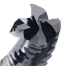
Discount
Material
Surface
Sutton
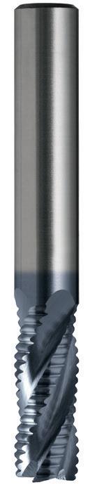
135 135 0600 6.0 60 15 10 3 E143 0600 0800 8.0 65 20 10 3 E143 0800 1000 10.0 75 25 10 4 E143 1000 1200 12.0 80 30 12 4 E143 1200 P Steel M Stainless Steel K Cast Iron N Non-Ferrous Metals S Titanium & Super Alloys H Hard Materials E143 VDI 3323 ISO • 1 P • 2 • 3 • 4 • 5 • 6 • 7 • 8 9 10 11 12 13 14.1 M 14.2 14.3 • 15 K 16 • 17 18 • 19 20 • 21 N • 22 • 23 • 24 25 • 26 27 • 28 29 30 31 S 32 33 34 35 36 37.1 37.2 37.3 37.4 37.5 • Optimal • Effective 38.1 H 38.2 39.1 39.2 40 41
E143
Catalogue Code
B0404
Group
HSS Co.8
Finish TiCN
WN Geometry R30 NR Shank Form (DIN 1835) A Shank Tolerance h6 Size Ref. d1 (js14) l1 l2 d2 z Item #
Regular 45º NR B Section Finder Contents Index
Designation
Roughers NR (normal), R30 WN,
For roughing applications
- NR geometry allows for heavy cuts
- Suitable for materials up to 1000 N/mm2
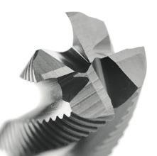
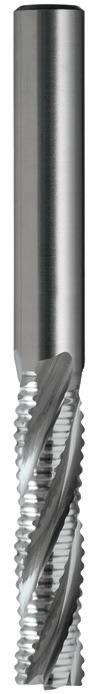
Catalogue Code E146
Discount Group B0402
Material HSS Co.8
Surface Finish Brt
Sutton Designation WN
Geometry R30 NR (coarse pitch)
Shank Form (DIN 1835) A Shank Tolerance h6
136 136 0600 6 68 24 6 3 E146 0600 0800 8 88 38 10 3 E146 0800 1000 10 95 45 10 4 E146 1000 1200 12 110 53 12 4 E146 1200 1600 16 123 63 16 4 E146 1600 1800 18 123 63 16 4 E146 1800 2000 20 141 75 20 4 E146 2000 2200 22 141 75 20 5 E146 2200 2500 25 166 90 25 5 E146 2500 3000 30 166 90 25 6 E146 3000 3200 32 186 106 32 6 • 1270 1/2 4-5/16 2-1/16 1/2 4 E146 1270 1588 5/8 4-27/32 2-1/2 5/8 4 E146 1588 1905 3/4 5-9/16 2-15/16 3/4 4 E146 1905 2540 1 6-9/16 3-9/16 1 5 E146 2540 3175 1-1/4 7-5/16 4-3/16 1-1/4 6 E146 3175 3810 1-1/2 8-17/32 4-29/32 1-1/4 6 E146 3810 P Steel M Stainless Steel K Cast Iron N Non-Ferrous Metals S Titanium & Super Alloys H Hard Materials E146 VDI 3323 ISO • 1 P • 2 • 3 • 4 5 • 6 7 8 9 10 11 12 13 14.1 M 14.2 14.3 15 K 16 17 18 19 20 • 21 N • 22 • 23 • 24 25 • 26 27 • 28 29 30 31 S 32 33 34 35 36 37.1 37.2 37.3 37.4 37.5 • Optimal • Effective 38.1 H 38.2 39.1 39.2 40 41 • Available on request as special manufacture. Subject to lead time.
-
Size Ref. d1 (js14) l1 l2 d2 z Item #
NR (normal), R30
Long 45º NR Vc Page #: 207 Section Finder Contents Index
Roughers
WN,
Slot Drills Ballnose, 2 Flute, R30 N, Long
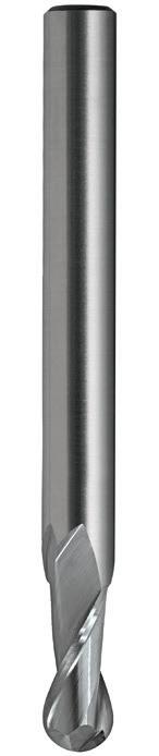
137 137 P Steel M Stainless Steel K Cast Iron N Non-Ferrous Metals S Titanium & Super Alloys H Hard Materials E113 VDI 3323 ISO • 1 P • 2 • 3 • 4 • 5 • 6 • 7 • 8 9 • 10 11 12 13 • 14.1 M • 14.2 14.3 • 15 K • 16 • 17 • 18 • 19 • 20 • 21 N • 22 • 23 • 24 • 25 • 26 27 • 28 29 30 31 S 32 33 34 35 36 37.1 37.2 37.3 37.4 37.5 • Optimal • Effective 38.1 H 38.2 39.1 39.2 40 41 0150 1.5 55 3 6 2 E113 0150 0200 2 55 4 6 2 E113 0200 0250 2.5 55 5 6 2 E113 0250 0300 3 60 6 6 2 E113 0300 0400 4 70 8 6 2 E113 0400 0450 4.5 70 8 6 2 • 0500 5 80 10 6 2 E113 0500 0600 6 90 12 6 2 E113 0600 0700 7 90 14 6 2 E113 0700 0800 8 100 16 8 2 E113 0800 0900 9 100 18 8 2 E113 0900 1000 10 100 20 10 2 E113 1000 1200 12 110 24 12 2 E113 1200 1400 14 110 28 12 2 E113 1400 1600 16 140 32 16 2 E113 1600 2000 20 160 40 20 2 E113 2000 2500 25 180 50 25 2 E113 2500 3000 30 180 55 25 2 E113 3000 • Available on request as special manufacture. Subject to lead time.
Catalogue Code E113 Discount Group B0502 Material HSS Co.8 Surface Finish Brt Sutton Designation N Geometry R30 Shank Form (DIN 1835) A Shank Tolerance h6 Size Ref. d1 (e8) l1 l2 d2 z Item #
- For long-reach profiling & contour milling applications - Suitable for materials up to 1000 N/mm2
Vc Page #: 207 Section Finder Contents Index
Roughers HR (fine), R30 NH, Regular
- For roughing applications
- HR geometry allows for heavy cuts, in harder materials
- Suitable for materials up to 1300 N/mm2
- TiCN for longer tool life
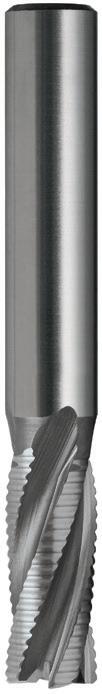
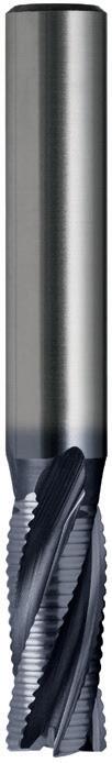
138 138 138 0600 6.0 60 15 10 3 E168 0600 E169 0600 0800 8.0 65 20 10 3 E168 0800 E169 0800 1000 10.0 75 25 10 4 E168 1000 E169 1000 1200 12.0 80 30 12 4 E168 1200 E169 1200 P Steel M Stainless Steel K Cast Iron N Non-Ferrous Metals S Titanium & Super Alloys H Hard Materials E169 E168 VDI 3323 ISO 1 P 2 • 3 4 • • 5 6 • • 7 • • 8 • • 9 • • 10 • • 11 • • 12 • • 13 • 14.1 M • 14.2 • 14.3 • • 15 K • 16 • • 17 • 18 • • 19 • 20 21 N 22 23 24 25 26 • • 27 28 29 30 31 S 32 33 34 35 36 37.1 37.2 37.3 37.4 37.5 • Optimal • Effective 38.1 H 38.2 39.1 39.2 • 40 41
Catalogue Code E168 E169 Discount Group B0402 B0404 Material HSS Co.8 HSS Co.8 Surface Finish Brt TiCN Sutton Designation NH NH Geometry R30 HR R30 HR Shank Form (DIN 1835) A A Shank Tolerance h6 h6 Size Ref. d1 (js14) l1 l2 d2 z Item # Item # HR B A Section Finder Contents Index
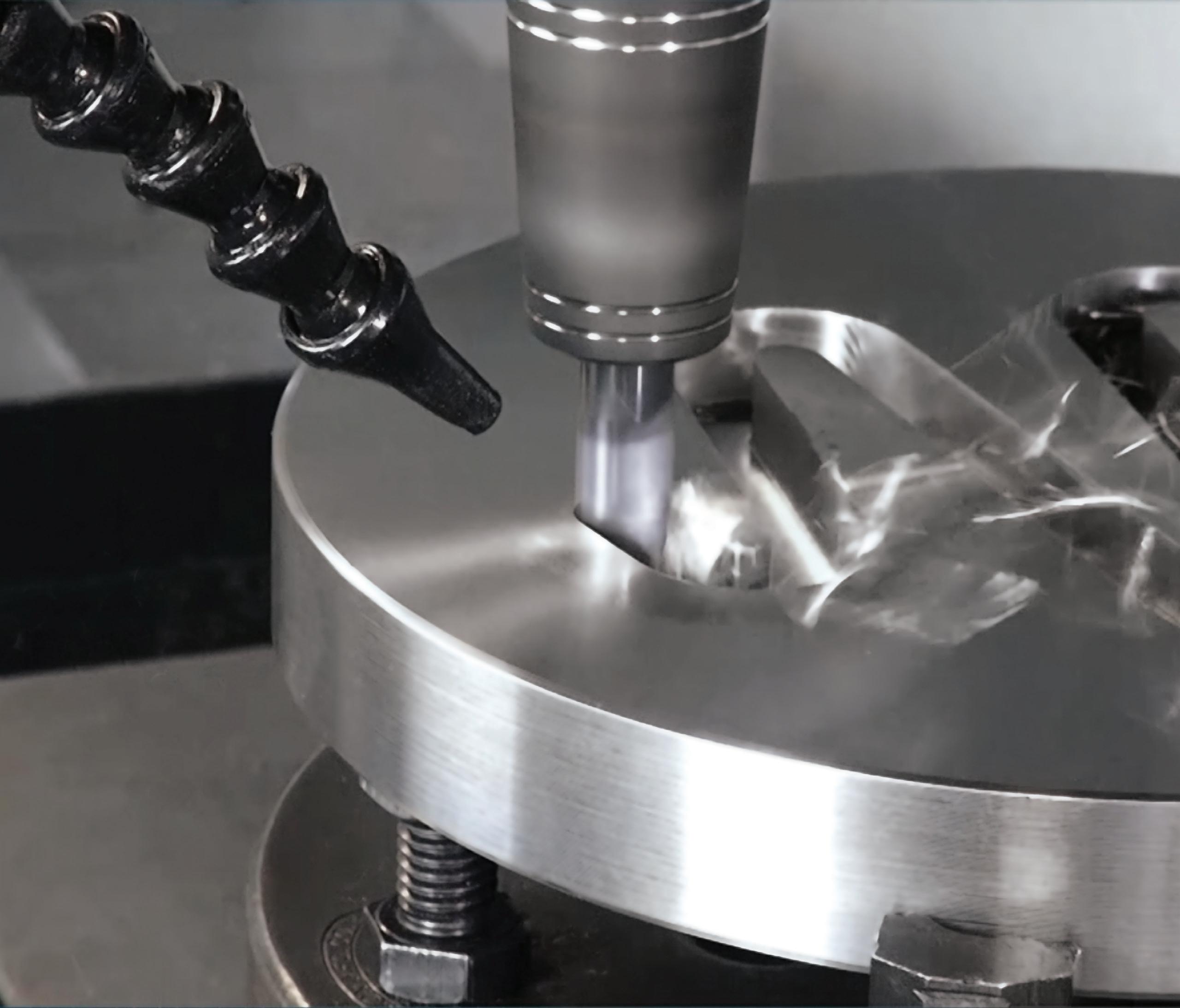
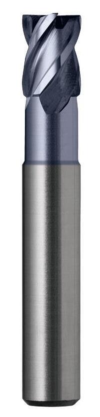
E533 R35/38 Short E535 R35/38 Regular
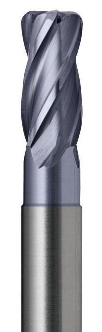
R35/38 Corner Radius
R45-HRS
Performance Unequalled…
Harmony Endmills
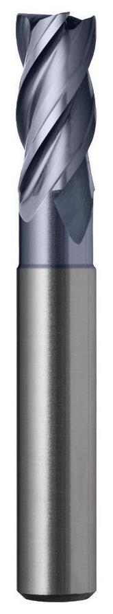
The Harmony range of Endmills represents world’s latest technologies to provide increases in both performance and tool life. The key to successful milling is to minimise or eliminate the harmonic vibration produced in the cutting action.
The Harmony Endmill overcomes vibration, through the latest technologies in tool engineering:
Premium Grade Carbide
• AlCrN Coating
• 35/38° Variable Helix
45° Corner Chamfering
• Gash grind of the endteeth
• Post grind treatment of cutting edges
The bottom line for you:
• Longer tool life
Improved surface finish
• Increased productivity
• Reduced production costs
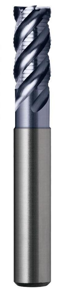
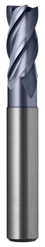
E549
E559
45º r Made from VHM-ULTRA, an Ultra Fine Grain Type of Carbide Recessed for Longer Reach Optimised Edge Conditioning 45°
Corner Radius (E559) Available
Corner Chamfering (E535)
35/38°
Unequal Flute Helix Endteeth Gash for Edge Strength
AICrN Coating for Longer Tool Life
Scan to watch the video
140 Section Finder Contents Index
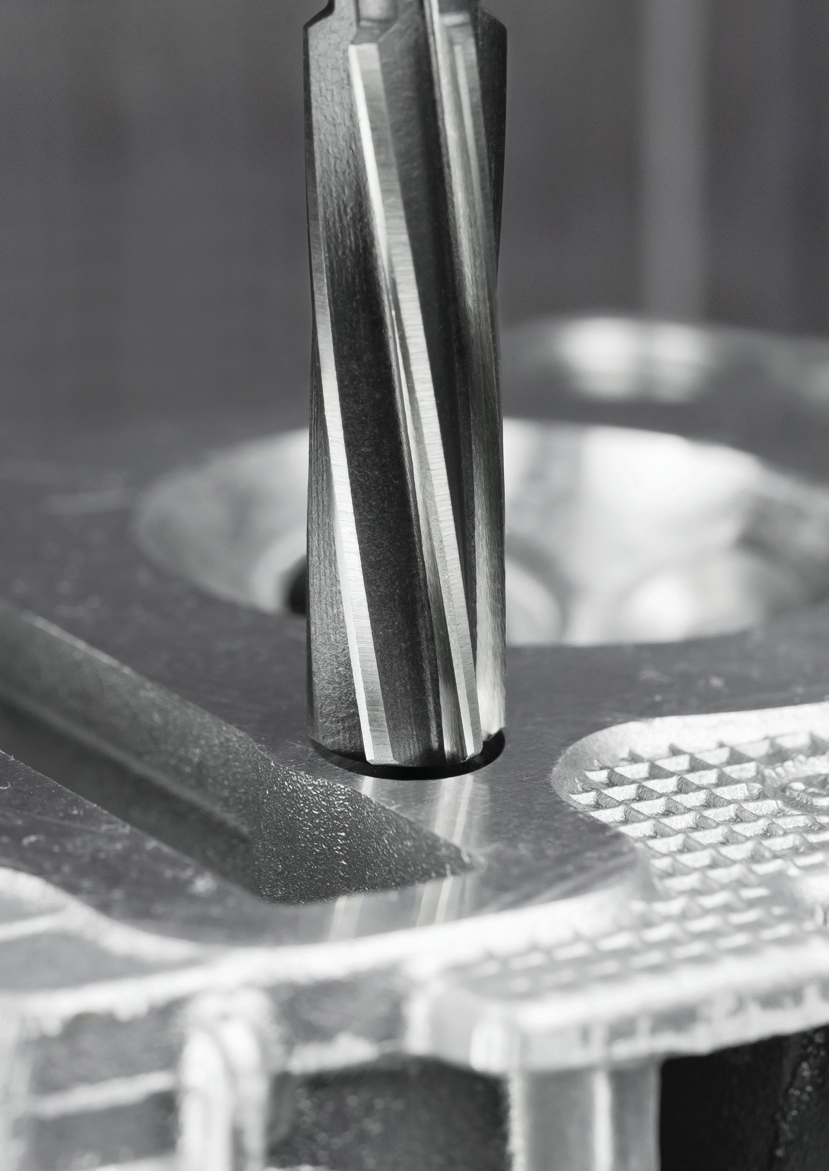
REAMERS
• Hand • Machine (Morse Taper & Chucking) • Bridge • Taper Pin
• Morse Taper Socket • Taper Pipe • Adjustable
AlCrN: G6 generation coatings... a quantum leap in tool wear resistance
Aluminium Chromium Nitride
The latest tool coating formula is Aluminium Chromium Nitride (AICrN). Coatings of this G6 generation developed, markedly expand the performance envelope versus conventional titanium based coatings (such as TiAIN, AITiN or TiCN).
Unique coating properties
The AICrN coating exhibits until now, an unmatched degree of oxidation resistance and hot hardness. These properties have triggered a quantum leap in tool wear resistance.
The bottom line: greater productivity!
Tools coated with AlCrN let you choose noticeably higher cutting speeds and allow you to more effectively exploit the potential of modern machine tools. You can produce more parts per time / unit to decisively boost the productivity of your manufacturing resources and hone your competitive edge.
Extraordinary performance gains have been demonstrated in dry and wet machining processes involving:
• Unalloyed steels
• High strength steels
• High hardness steels (up to 54 HRC)
Coating properties:
• Very high abrasion resistance
• High and constant temperature resistance
• Unrivalled oxidation resistance
• Titanium free coating
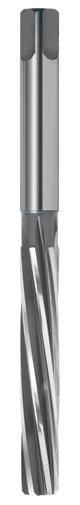
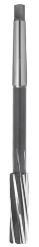
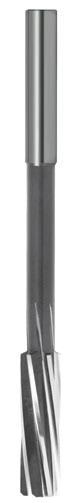
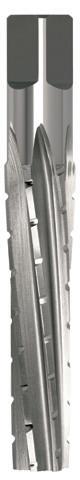
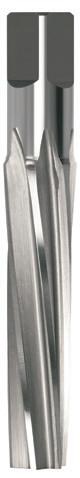
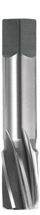
143 Reamers Finder • Optimal • Effective Page 144 146 149 150 151 152 152 153 154 Catalogue Code R100 R101 R102 R104 R105 R106 R107 R108 R109 Material HSS HSS HSS Co HSS HSS HSS HSS HSS TCA Surface Finish Brt Brt Brt Brt Brt Brt Brt Brt Brt Sutton Designation N N N N N Roughing Finishing Tapered Pipe N Standard DIN 206 / ISO 236 DIN 208 DIN 212 / ISO 521 – – – – – –Geometry L10 L10 L10 L15 L7 L7 L7 L15 Straight ISO VDI^ 3323 Material Condition HB N/mm2 P 1 Steel - Non-alloy, cast & free cutting ~ 0.15 %C A 125 440 • • • • • • • • • 2 ~ 0.45 %C A 190 640 • • • • • • • • • 3 QT 250 840 • • • • • • • • • 4 ~ 0.75 %C A 270 910 • • • • • • • • • 5 QT 300 1010 • • • • • • • • 6 Steel - Low alloy & cast < 5% of alloying elements A 180 610 • • • • • • • • • 7 QT 275 930 • • • • • • • • 8 QT 300 1010 • • • • • • • • 9 QT 350 1180 10 Steel - High alloy, cast & tool A 200 680 • • • • • • • • • 11 HT 325 1100 12 Steel - Corrosion resistant & cast Ferritic / Martensitic A 200 680 • • • • • • • • 13 Martensitic QT 240 810 M 14.1 Stainless Steel Austenitic AH 180 610 • • • • • • • • • 14.2 Duplex 250 840 • • • • • • • • 14.3 Precipitation Hardening 250 840 • • • • • • • • K 15 Cast Iron - Grey (GG) Ferritic / Pearlitic 180 610 • • • • • • • • • 16 Pearlitic 260 880 • • • • • • • • 17 Cast Iron - Nodular (GGG) Ferritic 160 570 • • • • • • • • 18 Pearlitic 250 840 • • • • • • • • 19 Cast Iron - Malleable Ferritic 130 460 • • • • • • • • 20 Pearlitic 230 780 • • • • • • • • N 21 Aluminum & Magnesium - wrought alloy Non Heat Treatable 60 210 • • • • • • • • • 22 Heat Treatable AH 100 360 • • • • • • • • • 23 Aluminum & Magnesium - cast alloy ≤12% Si Non Heat Treatable 75 270 • • • • • • • • • 24 Heat Treatable AH 90 320 • • • • • • • • • 25 Al & Mg - cast alloy >12% Si Non Heat Treatable 130 460 26 Copper & Cu alloys (Brass/Bronze) Free cutting, Pb > 1% 110 390 • • • • • • • • • 27 Brass (CuZn, CuSnZn) 90 320 • • • • • • • • 28 Bronze (CuSn) 100 360 • • • • • • • • • 29 Non-metallic - Thermosetting & fiber-reinforced plastics 30 Non-metallic - Hard rubber, wood etc. S 31 High temp. alloys Fe based A 200 680 32 AH 280 950 33 Ni / Co based A 250 840 34 AH 350 1180 35 C 320 1080 36 Titanium & Ti alloys CP Titanium 400 MPa 37.1 Alpha alloys 860 MPa 37.2 Alpha / Beta alloys A 960 MPa 37.3 AH 1170 MPa 37.4 Beta alloys A 830 MPa 37.5 AH 1400 MPa H 38.1 Hardened steel HT 45 HRC 38.2 HT 55 HRC 39.1 HT 58 HRC 39.2 HT 62 HRC 40 Cast Iron Chilled C 400 1350 • • • • • • • • 41 HT 55 HRC Condition: A (Annealed), AH (Age Hardened), C (Cast), HT (Hardened & Tempered), QT (Quenched & Tempered) ISO VDI Material Group Sutton P A Steel N UNI M R Stainless Steel VA K F Cast Iron GG N N Non-Ferrous Metals, Aluminiums & Coppers AI W S S Titaniums & Super Alloys Ti Ni H H Hard Materials (≥ 45 HRC) H ^ VDI 3323 material groups can also be determined by referring to the material cross reference listing in the application guide at the back of this catalogue. www.suttonhps.com Section Finder Contents
Reamers Hand
- For use by hand with suitable wrench
- Suitable for tool rooms & workshop use
- Produces clean, accurate holes, to a H7 tolerance
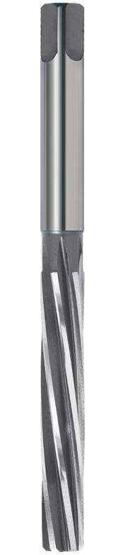
144 144 P Steel M Stainless Steel K Cast Iron N Non-Ferrous Metals S Titanium & Super Alloys H Hard Materials R100 VDI 3323 ISO • 1 P • 2 • 3 • 4 • 5 • 6 • 7 • 8 9 • 10 11 • 12 13 • 14.1 M • 14.2 • 14.3 • 15 K • 16 • 17 • 18 • 19 • 20 • 21 N • 22 • 23 • 24 25 • 26 • 27 • 28 29 30 31 S 32 33 34 35 36 37.1 37.2 37.3 37.4 37.5 • Optimal • Effective 38.1 H 38.2 39.1 39.2 • 40 41 0300 3.000 62 31 - - 6 R100 0300 0318 3.175 1/8 66 33 - - 6 R100 0318 0350 3.500 71 35 - - 6 R100 0350 0357 3.572 9/64 71 35 - - 6 R100 0357 0397 3.969 5/32 76 38 - - 6 R100 0397 0400 4.000 76 38 - - 6 R100 0400 0437 4.366 11/64 81 41 - - 6 R100 0437 0450 4.500 81 41 - - 6 R100 0450 0476 4.762 3/16 87 44 - - 6 R100 0476 0500 5.000 87 44 - - 6 R100 0500 0516 5.159 13/64 87 44 - - 6 R100 0516 0550 5.500 93 47 - - 6 R100 0550 0556 5.556 7/32 93 47 - - 6 R100 0556 0595 5.953 15/64 93 47 - - 6 R100 0595 0600 6.000 93 47 - - 6 R100 0600 0635 6.350 1/4 100 50 - - 6 R100 0635 0650 6.500 100 50 - - 6 R100 0650 0675 6.747 17/64 100 50 - - 6 R100 0675 0700 7.000 107 54 - - 6 R100 0700 0714 7.144 9/32 107 54 - - 6 R100 0714 0750 7.500 107 54 - - 6 R100 0750 0754 7.541 19/64 107 54 - - 6 R100 0754 0794 7.938 5/16 115 58 - - 6 R100 0794 0800 8.000 115 58 - - 6 R100 0800 0833 8.334 21/64 115 58 - - 6 R100 0833 0850 8.500 115 58 - - 6 R100 0850 0873 8.731 11/32 124 62 - - 6 R100 0873 0900 9.000 124 62 - - 6 R100 0900 0913 9.128 23/64 124 62 - - 8 R100 0913 0950 9.500 124 62 - - 6 R100 0950 0953 9.525 3/8 133 66 - - 8 R100 0953 0992 9.922 25/64 133 66 - - 8 R100 0992 1000 10.000 133 66 - - 6 R100 1000 1032 10.319 13/32 133 66 - - 8 R100 1032 1050 10.500 133 66 - - 6 R100 1050 1100 11.000 142 71 - - 6 R100 1100 1111 11.112 7/16 142 71 - - 8 R100 1111 1150 11.500 142 71 - - 6 R100 1150 1151 11.509 29/64 142 71 - - 8 R100 1151 1191 11.906 15/32 152 76 - - 8 R100 1191 H7
Catalogue Code R100 Discount Group B0302 Material HSS Surface Finish Brt Sutton Designation N Geometry L10 Size Ref. d1 l1 l2 l3 d2 z Item # Section Finder Contents Index
Reamers Hand
- For use by hand with suitable wrench
- Suitable for tool rooms & workshop use
- Produces clean, accurate holes, to a H7 tolerance
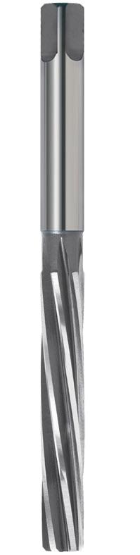
145 P Steel M Stainless Steel K Cast Iron N Non-Ferrous Metals S Titanium & Super Alloys H Hard Materials R100 VDI 3323 ISO • 1 P • 2 • 3 • 4 • 5 • 6 • 7 • 8 9 • 10 11 • 12 13 • 14.1 M • 14.2 • 14.3 • 15 K • 16 • 17 • 18 • 19 • 20 • 21 N • 22 • 23 • 24 25 • 26 • 27 • 28 29 30 31 S 32 33 34 35 36 37.1 37.2 37.3 37.4 37.5 • Optimal • Effective 38.1 H 38.2 39.1 39.2 • 40 41 1200 12.000 152 76 - - 6 R100 1200 1230 12.303 31/64 152 76 - - 8 R100 1230 1250 12.500 152 76 - - 6 R100 1250 1270 12.700 1/2 152 76 - - 8 R100 1270 1300 13.000 152 76 - - 6 R100 1300 1310 13.097 33/64 152 76 - - 8 R100 1310 1349 13.494 17/32 163 81 - - 8 R100 1349 1389 13.891 35/64 163 81 - - 8 R100 1389 1350 13.500 163 81 - - 6 R100 1350 1400 14.000 163 81 - - 8 R100 1400 1429 14.288 9/16 163 81 - - 8 R100 1429 1450 14.500 163 81 - - 8 R100 1450 1468 14.684 37/64 163 81 - - 8 R100 1468 1500 15.000 163 81 - - 8 R100 1500 1508 15.081 19/32 175 87 - - 8 R100 1508 1548 15.478 39/64 175 87 - - 8 R100 1548 1588 15.875 5/8 175 87 - - 8 R100 1588 1600 16.000 175 87 - - 8 R100 1600 1627 16.272 41/64 175 87 - - 8 R100 1627 1667 16.669 21/32 175 87 - - 8 R100 1667 1700 17.000 175 87 - - 8 R100 1700 1707 17.066 43/64 188 93 - - 8 R100 1707 1746 17.463 11/16 188 93 - - 8 R100 1746 1800 18.000 188 93 - - 8 R100 1800 1826 18.256 23/32 188 93 - - 8 R100 1826 1900 19.000 188 93 - - 8 R100 1900 1905 19.050 3/4 201 100 - - 10 R100 1905 1984 19.844 25/32 201 100 - - 10 R100 1984 2000 20.000 201 100 - - 8 R100 2000 2064 20.638 13/16 201 100 - - 10 R100 2064 2100 21.000 201 100 - - 8 R100 2100 2143 21.431 27/32 215 107 - - 10 R100 2143 2200 22.000 215 107 - - 8 R100 2200 2223 22.225 7/8 215 107 - - 10 R100 2223 2300 23.000 215 107 - - 8 R100 2300 2302 23.019 29/32 215 107 - - 10 R100 2302 2381 23.813 15/16 231 115 - - 10 R100 2381 2400 24.000 231 115 - - 8 R100 2400 2461 24.606 31/32 231 115 - - 10 R100 2461 2500 25.000 231 115 - - 10 R100 2500 2540 25.400 1 231 115 - - 10 R100 2540 H7
Catalogue Code R100 Discount Group B0302 Material HSS Surface Finish Brt Sutton Designation N Geometry L10 Size Ref. d1 l1 l2 l3 d2 z Item # Section Finder Contents Index
Reamers Machine
- Machine use
- Suitable for toolroom & workshop use
- Produces clean, accurate holes, to a H7 tolerance
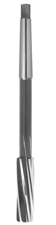
Catalogue Code R101
Discount Group B0302
Material HSS
Surface Finish Brt
Sutton Designation N
Geometry L10
146 146 P Steel M Stainless Steel K Cast Iron N Non-Ferrous Metals S Titanium & Super Alloys H Hard Materials R101 VDI 3323 ISO • 1 P • 2 • 3 • 4 • 5 • 6 • 7 • 8 9 • 10 11 • 12 13 • 14.1 M • 14.2 • 14.3 • 15 K • 16 • 17 • 18 • 19 • 20 • 21 N • 22 • 23 • 24 25 • 26 • 27 • 28 29 30 31 S 32 33 34 35 36 37.1 37.2 37.3 37.4 37.5 • Optimal • Effective 38.1 H 38.2 39.1 39.2 • 40 41 0600 6.000 138 26 - - 6 1 R101 0600 0635 6.350 1/4 144 28 - - 6 1 R101 0635 0650 6.500 144 28 - - 6 1 R101 0650 0675 6.747 17/64 144 28 - - 6 1 R101 0675 0700 7.000 150 31 - - 6 1 R101 0700 0714 7.144 9/32 150 31 - - 6 1 R101 0714 0750 7.500 150 31 - - 6 1 R101 0750 0754 7.541 19/64 150 31 - - 6 1 R101 0754 0794 7.938 5/16 156 33 - - 6 1 R101 0794 0800 8.000 156 33 - - 6 1 R101 0800 0833 8.334 21/64 156 33 - - 6 1 R101 0833 0850 8.500 156 33 - - 6 1 R101 0850 0873 8.731 11/32 162 36 - - 6 1 R101 0873 0900 9.000 162 36 - - 6 1 R101 0900 0913 9.128 23/64 162 36 - - 6 1 R101 0913 0950 9.500 162 36 - - 6 1 R101 0950 0953 9.525 3/8 162 36 - - 6 1 R101 0953 0992 9.922 25/64 168 38 - - 6 1 R101 0992 1000 10.000 168 38 - - 6 1 R101 1000 1032 10.319 13/32 168 38 - - 6 1 R101 1032 1050 10.500 168 38 - - 6 1 R101 1050 1072 10.716 27/64 175 41 - - 6 1 R101 1072 1100 11.000 175 41 - - 6 1 R101 1100 1111 11.112 7/16 175 41 - - 6 1 R101 1111 1150 11.500 175 41 - - 6 1 R101 1150 1151 11.509 29/64 175 41 - - 6 1 R101 1151 1191 11.906 15/32 175 41 - - 6 1 R101 1191 1200 12.000 182 44 - - 6 1 R101 1200 1230 12.303 31/64 182 44 - - 6 1 R101 1230 1250 12.500 182 44 - - 6 1 R101 1250 1270 12.700 1/2 182 44 - - 6 1 R101 1270 1300 13.000 182 44 - - 6 1 R101 1300 1310 13.097 33/64 182 44 - - 6 1 R101 1310 1349 13.494 17/32 189 47 - - 6 1 R101 1349 1350 13.500 189 47 - - 6 1 R101 1350 1389 13.891 35/64 189 47 - - 6 1 R101 1389 1400 14.000 189 47 - - 8 1 R101 1400 1429 14.288 9/16 204 50 - - 8 2 R101 1429 1450 14.500 204 50 - - 8 2 R101 1450 1468 14.684 37/64 204 50 - - 8 2 R101 1468
H7
Size Ref. d1 l1 l2 l3 d2 z MT # Item #
Section Finder Contents Index
Reamers Machine
- Machine use
- Suitable for toolroom & workshop use
- Produces clean, accurate holes, to a H7 tolerance
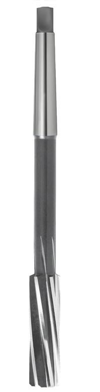
147 P Steel M Stainless Steel K Cast Iron N Non-Ferrous Metals S Titanium & Super Alloys H Hard Materials R101 VDI 3323 ISO • 1 P • 2 • 3 • 4 • 5 • 6 • 7 • 8 9 • 10 11 • 12 13 • 14.1 M • 14.2 • 14.3 • 15 K • 16 • 17 • 18 • 19 • 20 • 21 N • 22 • 23 • 24 25 • 26 • 27 • 28 29 30 31 S 32 33 34 35 36 37.1 37.2 37.3 37.4 37.5 • Optimal • Effective 38.1 H 38.2 39.1 39.2 • 40 41 1500 15.000 204 50 - - 8 2 R101 1500 1508 15.081 19/32 210 52 - - 8 2 R101 1508 1550 15.500 210 52 - - 8 2 R101 1550 1548 15.478 39/64 210 52 - - 8 2 R101 1548 1588 15.875 5/8 210 52 - - 8 2 R101 1588 1600 16.000 210 52 - - 8 2 R101 1600 1627 16.272 41/64 214 54 - - 8 2 R101 1627 1650 16.500 214 54 - - 8 2 R101 1650 1667 16.669 21/32 214 54 - - 8 2 R101 1667 1700 17.000 214 54 - - 8 2 R101 1700 1707 17.066 43/64 219 56 - - 8 2 R101 1707 1746 17.463 11/16 219 56 - - 8 2 R101 1746 1750 17.500 219 56 - - 8 2 R101 1750 1786 17.859 45/64 219 56 - - 8 2 R101 1786 1800 18.000 219 56 - - 8 2 R101 1800 1826 18.256 23/32 219 56 - - 8 2 R101 1826 1850 18.500 223 58 - - 8 2 R101 1850 1900 19.000 223 58 - - 8 2 R101 1900 1905 19.050 3/4 223 58 - - 8 2 R101 1905 1950 19.500 228 60 - - 8 2 R101 1950 2000 20.000 228 60 - - 8 2 R101 2000 2050 20.500 232 62 - - 8 2 R101 2050 2064 20.638 13/16 232 62 - - 8 2 R101 2064 2100 21.000 232 62 - - 8 2 R101 2100 2143 21.431 27/32 232 62 - - 8 2 R101 2143 2150 21.500 237 64 - - 8 2 R101 2150 2200 22.000 237 64 - - 8 2 R101 2200 2223 22.225 7/8 237 64 - - 8 2 R101 2223 2250 22.500 241 66 - - 8 2 R101 2250 2300 23.000 241 66 - - 8 2 R101 2300 2302 23.019 29/32 237 64 - - 8 2 R101 2302 2350 23.500 241 66 - - 8 3 R101 2350 2381 23.813 15/16 268 68 - - 8 3 R101 2381 2400 24.000 268 68 - - 8 3 R101 2400 2450 24.500 268 68 - - 8 3 R101 2450 2461 24.606 31/32 268 68 - - 8 3 R101 2461 2500 25.000 268 68 - - 10 3 R101 2500 2540 25.400 1 268 68 - - 8 3 R101 2540 2550 25.500 273 70 - - 10 3 R101 2550 2600 26.000 273 70 - - 10 3 R101 2600
H7
Catalogue Code R101 Discount Group B0302 Material HSS Surface Finish Brt Sutton Designation N Geometry L10 Size Ref. d1 l1 l2 l3 d2 z MT # Item # Section Finder Contents Index
Reamers Machine
- Machine use
- Suitable for toolroom & workshop use
- Produces clean, accurate holes, to a H7 tolerance

148 P Steel M Stainless Steel K Cast Iron N Non-Ferrous Metals S Titanium & Super Alloys H Hard Materials R101 VDI 3323 ISO • 1 P • 2 • 3 • 4 • 5 • 6 • 7 • 8 9 • 10 11 • 12 13 • 14.1 M • 14.2 • 14.3 • 15 K • 16 • 17 • 18 • 19 • 20 • 21 N • 22 • 23 • 24 25 • 26 • 27 • 28 29 30 31 S 32 33 34 35 36 37.1 37.2 37.3 37.4 37.5 • Optimal • Effective 38.1 H 38.2 39.1 39.2 • 40 41 2650 26.500 273 70 - - 10 3 R101 2650 2699 26.987 1-1/16 277 71 - - 10 3 R101 2699 2700 27.000 277 71 - - 10 3 R101 2700 2750 27.500 277 71 - - 10 3 R101 2750 2800 28.000 277 71 - - 10 3 R101 2800 2850 28.500 281 73 - - 10 3 R101 2850 2858 28.575 1-1/8 281 73 - - 10 3 R101 2858 2900 29.000 281 73 - - 10 3 R101 2900 2950 29.500 281 73 - - 10 3 R101 2950 3000 30.000 281 73 - - 10 3 R101 3000 3016 30.162 1-3/16 285 75 - - 10 3 R101 3016 3050 30.500 285 75 - - 10 3 R101 3050 3100 31.000 285 75 - - 10 3 R101 3100 3150 31.500 285 75 - - 10 3 R101 3150 3175 31.750 1-1/4 290 77 - - 10 3 R101 3175 3200 32.000 317 77 - - 10 4 R101 3200 3300 33.000 317 77 - - 10 4 R101 3300 3334 33.338 1-5/16 317 77 - - 10 4 R101 3334 3400 34.000 321 78 - - 10 4 R101 3400 3493 34.925 1-3/8 321 78 - - 10 4 R101 3493 3500 35.000 321 78 - - 10 4 R101 3500 3600 36.000 325 79 - - 12 4 R101 3600 3651 36.512 1-7/16 325 79 - - 12 4 R101 3651 3700 37.000 325 79 - - 12 4 R101 3700 3800 38.000 329 81 - - 12 4 R101 3800 3810 38.100 1-1/2 329 83 - - 12 4 R101 3810 3900 39.000 329 81 - - 12 4 R101 3900 4000 40.000 329 81 - - 12 4 R101 4000 4128 41.275 1-5/8 333 82 - - 12 4 R101 4128 4445 44.450 1-3/4 336 83 - - 12 4 R101 4445 4763 47.625 1-7/8 344 86 - - 12 4 R101 4763 5080 50.800 2 344 86 - - 12 4 R101 5080 H7
Catalogue Code R101 Discount Group B0302 Material HSS Surface Finish Brt Sutton Designation N Geometry L10 Size Ref. d1 l1 l2 l3 d2 z MT # Item # Section Finder Contents Index
Reamers Chucking
- Machine use
- Suitable for toolroom & workshop use
- Produces clean, accurate holes, to a H7 tolerance
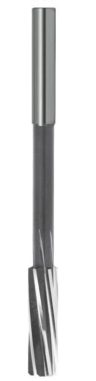
149 149 P Steel M Stainless Steel K Cast Iron N Non-Ferrous Metals S Titanium & Super Alloys H Hard Materials R102 VDI 3323 ISO • 1 P • 2 • 3 • 4 • 5 • 6 • 7 • 8 9 • 10 11 • 12 13 • 14.1 M • 14.2 • 14.3 • 15 K • 16 • 17 • 18 • 19 • 20 • 21 N • 22 • 23 • 24 25 • 26 • 27 • 28 29 30 31 S 32 33 34 35 36 37.1 37.2 37.3 37.4 37.5 • Optimal • Effective 38.1 H 38.2 39.1 39.2 • 40 41 0200 2.000 49 11 - 2.0 3 R102 0200 0250 2.500 57 14 - 2.5 5 R102 0250 0300 3.000 61 15 - 3.0 5 R102 0300 0318 3.175 1/8 65 16 - 3.2 5 R102 0318 0350 3.500 70 18 - 3.5 5 R102 0350 0357 3.572 9/64 70 18 - 3.6 5 R102 0357 0397 3.969 5/32 75 19 - 4.0 6 R102 0397 0400 4.000 75 19 - 4.0 6 R102 0400 0450 4.500 80 21 - 4.5 6 R102 0450 0476 4.762 3/16 86 23 - 5.0 6 R102 0476 0500 5.000 86 23 - 5.0 6 R102 0500 0516 5.159 13/64 86 23 - 5.0 6 R102 0516 0550 5.500 93 26 - 5.6 6 R102 0550 0595 5.953 15/64 93 26 - 5.6 6 R102 0595 0600 6.000 93 26 - 5.6 6 R102 0600 0635 6.350 1/4 101 28 - 6.3 6 R102 0635 0650 6.500 101 28 - 6.3 6 R102 0650 0700 7.000 109 31 - 7.1 6 R102 0700 0750 7.500 109 31 - 7.1 6 R102 0750 0794 7.938 5/16 117 31 - 8.0 6 R102 0794 0800 8.000 117 33 - 8.0 6 R102 0800 0850 8.500 117 33 - 8.0 6 R102 0850 0900 9.000 125 36 - 9.0 6 R102 0900 0950 9.500 125 36 - 9.0 6 R102 0950 0953 9.525 3/8 133 38 - 10.0 6 R102 0953 1000 10.000 133 38 - 10.0 6 R102 1000 1050 10.500 133 38 - 10.0 6 R102 1050 1100 11.000 142 41 - 10.0 6 R102 1100 1111 11.112 7/16 142 41 - 10.0 6 R102 1111 1150 11.500 142 41 - 10.0 6 R102 1150 1200 12.000 151 44 - 10.0 6 R102 1200 1250 12.500 151 44 - 10.0 6 R102 1250 1270 12.700 1/2 151 44 - 10.0 6 R102 1270 1300 13.000 151 44 - 10.0 6 R102 1300 1350 13.500 160 47 - 12.5 6 R102 1350 1400 14.000 160 47 - 12.5 8 R102 1400 1429 14.288 9/16 162 50 - 12.5 8 R102 1429 1450 14.500 162 50 - 12.5 8 R102 1450 1500 15.000 162 50 - 12.5 8 R102 1500 1550 15.500 170 52 - 12.5 8 R102 1550 1588 15.875 5/8 170 52 - 12.5 8 R102 1588 1600 16.000 170 52 - 12.5 8 R102 1600 H7
Catalogue Code R102 Discount Group B0302 Material HSS Co Surface Finish Brt Sutton Designation N Geometry L10 Size Ref. d1 l1 l2 l3 d2 z Item # Section Finder Contents Index
- Machine use
- For opening out existing holes
- Ideal for alignment in fabrication & construction work
Catalogue Code R104
Discount Group B0302
Material HSS
Surface Finish Brt
Sutton Designation N
Geometry L15
150 150 P Steel M Stainless Steel K Cast Iron N Non-Ferrous Metals S Titanium & Super Alloys H Hard Materials R104 VDI 3323 ISO • 1 P • 2 • 3 • 4 • 5 • 6 • 7 • 8 9 • 10 11 • 12 13 • 14.1 M • 14.2 • 14.3 • 15 K • 16 • 17 • 18 • 19 • 20 • 21 N • 22 • 23 • 24 25 • 26 • 27 • 28 29 30 31 S 32 33 34 35 36 37.1 37.2 37.3 37.4 37.5 • Optimal • Effective 38.1 H 38.2 39.1 39.2 • 40 41 1300 13.0 199 105 42 8.8 5 2 R104 1300 1400 14.0 209 115 46 9.4 5 2 R104 1400 1600 16.0 229 135 54 10.6 5 2 R104 1600 1700 17.0 251 135 54 11.6 5 3 R104 1700 1800 18.0 261 145 58 12.2 5 3 R104 1800 1900 19.0 261 145 58 13.2 5 3 R104 1900 2000 20.0 271 155 62 13.8 5 3 R104 2000 2100 21.0 271 155 62 14.8 5 3 R104 2100 2200 22.0 281 165 66 15.4 5 3 R104 2200 2300 23.0 281 165 66 16.4 5 3 R104 2300 2500 25.0 296 180 72 17.8 5 3 R104 2500 2600 26.0 296 180 72 18.8 5 3 R104 2600 2800 28.0 311 195 78 20.2 5 3 R104 2800 3000 30.0 311 195 78 22.2 5 3 R104 3000 3200 32.0 354 210 84 23.6 5 4 R104 3200
Reamers Bridge
Size Ref. d1 l1 l2 l3 d2 z MT # Item # Section Finder Contents Index
Reamers Taper Pin
- For use by hand with suitable wrench - For opening out parallel holes to suit 1:48 taper pins
151 151 P Steel M Stainless Steel K Cast Iron N Non-Ferrous Metals S Titanium & Super Alloys H Hard Materials R105 VDI 3323 ISO • 1 P • 2 • 3 • 4 • 5 • 6 • 7 • 8 9 • 10 11 • 12 13 • 14.1 M • 14.2 • 14.3 • 15 K • 16 • 17 • 18 • 19 • 20 • 21 N • 22 • 23 • 24 25 • 26 • 27 • 28 29 30 31 S 32 33 34 35 36 37.1 37.2 37.3 37.4 37.5 • Optimal • Effective 38.1 H 38.2 39.1 39.2 • 40 41 0238 3/32 #5/0 57 32 1.75 3.0 2.41 4 R105 0238 0278 7/64 #4/0 57 32 2.23 3.0 2.89 4 R105 0278 0318 1/8 #3/0 62 35 2.56 3.5 3.29 4 R105 0318 0357 9/64 #2/0 70 38 2.89 4.0 3.68 4 R105 0357 0397 5/32 #0 70 42 3.22 4.5 4.10 6 R105 0397 0437 11/64 #1 75 45 3.70 5.0 4.64 6 R105 0437 0476 3/16 #2 82 52 4.11 5.5 5.19 6 R105 0476 0556 7/32 #3 90 58 4.64 6.0 5.85 6 R105 0556 0635 1/4 #4 105 65 5.28 6.5 6.63 6 R105 0635 0714 9/32 #5 115 78 6.09 6.5 7.72 6 R105 0714 0873 11/32 #6 130 92 7.08 7.5 9.00 6 R105 0873 1032 13/32 #7 155 115 8.40 9.0 10.80 6 R105 1032 1270 1/2 #8 175 135 10.11 11.0 12.92 6 R105 1270 1429 9/16 #9 205 155 12.24 14.5 15.47 6 R105 1429 1905 3/4 #10 230 180 14.75 16.0 18.50 6 R105 1905 2223 7/8 #11 285 210 17.93 19.0 22.31 6 R105 2223 d3
Catalogue Code R105 Discount Group B0302 Material HSS Surface Finish Brt Sutton Designation N Geometry L7 Size Ref. BS Size Series l1 l2 d1 d2 d3 z Item #
Section Finder Contents Index
Reamers Morse Taper Socket
Suitable
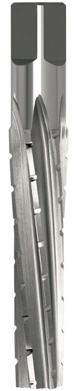
Reamers Morse Taper Socket
- For use by hand with suitable wrench
- Suitable for tool rooms & workshop use
- Rougher,
-
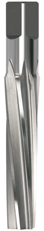
Sutton Designation Finishing Geometry L10
152 152 152 P Steel M Stainless Steel K Cast Iron N Non-Ferrous Metals S Titanium & Super Alloys H Hard Materials R107 R106 VDI 3323 ISO • • 1 P • • 2 • • 3 • • 4 • • 5 • • 6 • • 7 • • 8 9 • • 10 11 • • 12 13 • • 14.1 M • • 14.2 • • 14.3 • • 15 K • • 16 • • 17 • • 18 • • 19 • • 20 • • 21 N • • 22 • • 23 • • 24 25 • • 26 • • 27 • • 28 29 30 31 S 32 33 34 35 36 37.1 37.2 37.3 37.4 37.5 • Optimal • Effective 38.1 H 38.2 39.1 39.2 • • 40 41 0000 0 95 62 6.29 8.00 9.51 6 R106 0000 0001 1 100 67 9.32 10.00 12.66 6 R106 0001 0002 2 125 80 14.48 14.00 18.48 8 R106 0002 0003 3 150 97 19.66 19.00 24.53 8 R106 0003 0004 4 180 120 25.81 24.00 32.05 10 R106 0004 0005 5 225 151 37.30 31.50 45.24 10 R106 0005 0000 0 95 62 6.29 8.00 9.51 6 R107 0000 0001 1 100 67 9.32 10.00 12.66 6 R107 0001 0002 2 125 80 14.48 14.00 18.48 8 R107 0002 0003 3 150 97 19.66 19.00 24.53 8 R107 0003 0004 4 180 120 25.81 24.00 32.05 10 R107 0004 0005 5 225 151 37.30 31.50 45.24 10 R107 0005 d3
- For use by hand with suitable wrench -
for tool rooms & workshop use - Rougher, opens out existing parallel holes - Finishing, to be used after rougher for final sizing
holes
opens out existing parallel
Finishing,
after
for final sizing
to be used
rougher
Catalogue Code R106 Discount Group B0302 Material HSS Surface Finish Brt Sutton Designation Roughing Geometry L10 Size Ref. MT # l1 l2 d1 d2 d3 z Item #
R107
Catalogue Code
Discount Group B0302 Material HSS Surface Finish Brt
Size Ref. MT # l1 l2 d1 d2 d3 z Item # d3 Section Finder Contents Index
Reamers Taper Pipe
- For use by hand with suitable wrench
- Suitable for tool rooms & workshop use
- Used prior to tapping tapered thread forms 1:16 taper (BSPT, NPT)
- Prolongs tap life, especially in tough materials
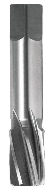
153 153 P Steel M Stainless Steel K Cast Iron N Non-Ferrous Metals S Titanium & Super Alloys H Hard Materials R108 VDI 3323 ISO • 1 P • 2 • 3 • 4 • 5 • 6 • 7 • 8 9 • 10 11 • 12 13 • 14.1 M • 14.2 • 14.3 • 15 K • 16 • 17 • 18 • 19 • 20 • 21 N • 22 • 23 • 24 25 • 26 • 27 • 28 29 30 31 S 32 33 34 35 36 37.1 37.2 37.3 37.4 37.5 • Optimal • Effective 38.1 H 38.2 39.1 39.2 • 40 41 0803 1/8 8.00 60 15 8.00 8.97 6 R108 0803 1031 1/4 10.31 67 20 10.00 11.50 6 R108 1031 1372 3/8 13.72 75 22 12.50 15.63 6 R108 1372 1689 1/2 16.89 87 26 16.00 18.52 6 R108 1689 2225 3/4 22.25 96 29 20.00 24.00 6 R108 2225 2802 1 28.00 110 33 25.00 30.08 6 R108 2802 3668 1-1/4 36.58 119 37 31.50 38.83 6 R108 3668 4277 1-1/2 42.77 125 37 35.50 45.08 8 R108 4277 5484 2 54.84 140 41 40.00 57.40 8 R108 5484
d3
d2
Catalogue Code R108 Discount Group B0302 Material HSS Surface Finish Brt Sutton Designation Tapered Pipe Geometry L15 Size Ref. Size d1 l1 l2 d2 d3 z Item #
Section Finder Contents Index
Reamers Adjustable
- For use by hand with suitable wrench
- General purpose
- Adjustable size range
- TCA (Tungsten Chrome Alloy)
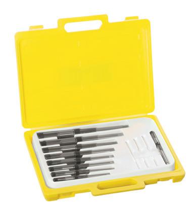
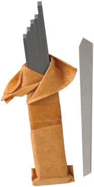
154 154 P Steel M Stainless Steel K Cast Iron N Non-Ferrous Metals S Titanium & Super Alloys H Hard Materials R109 VDI 3323 ISO • 1 P • 2 • 3 • 4 5 • 6 7 8 9 • 10 11 12 13 • 14.1 M 14.2 14.3 • 15 K 16 17 18 19 20 • 21 N • 22 • 23 • 24 25 • 26 27 • 28 29 30 31 S 32 33 34 35 36 37.1 37.2 37.3 37.4 37.5 • Optimal • Effective 38.1 H 38.2 39.1 39.2 40 41 0635 MA8 6.35–7.15 1/4–9/32 2.8 R109 0635 0715 MA7 7.15–7.95 9/32–5/16 3.2 R109 0715 0795 MA6 7.95–8.70 5/16–11/32 4 R109 0795 0870 MA5 8.70–9.50 11/32–3/8 4 R109 0870 0950 MA4 9.50–10.25 3/8–13/32 4 R109 0950 1025 MA3 10.25–11.00 13/32–7/16 4.5 R109 1025 1100 MA2 11.00–12.00 7/16–15/32 5.5 R109 1100 1200 MA 12.00–13.50 15/32–17/32 5.5 R109 1200 R110 1200 1350 MB 13.50–15.00 17/32–19/32 6.5 R109 1350 R110 1350 1500 MC 15.00–16.75 19/32–21/32 7 R109 1500 R110 1500 1675 MD 16.75–18.25 21/32–23/32 8 R109 1675 R110 1675 1825 ME 18.25–19.75 23/32–25/32 9 R109 1825 R110 1825 1975 MF 19.75–21.50 25/32–27/32 10 R109 1975 R110 1975 2150 MG 21.50–23.75 27/32–15/16 12 R109 2150 R110 2150 2375 MH 23.75–27.00 15/16–1-1/16 13 R109 2375 R110 2375 2700 MI 27.00–30.25 1-1/16–1-3/16 15 R109 2700 R110 2700 3025 MJ 30.25–34.25 1-3/16–1-11/32 15 R109 3025 R110 3025 3425 MK 34.25–38.00 1-11/32–1-1/2 17 R109 3425 R110 3425 3800 ML 38.00–46.00 1-1/2–1-13/16 21 R109 3800 R110 3800 4600 MM 46.00–56.00 1-13/16–2-7/32 26 R109 4600 R110 4600 5600 MN 56.00–69.75 2-7/32–2-3/4 32 R109 5600 R110 5600 6975 MO 69.75–85.00 2-3/4–3-11/32 38 R109 6975 R110 6975 Adjustable
Set Pieces M1 MA4 to ME (Reamers Only) 8 R109 M1 M2P MA to MH (Reamers & Pilots) 16 R109 M2P M3 MA4 to MH (Reamers Only) 11 R109 M3 M6 MA8 to MK (Reamers Only) 18 R109 M6 M8 MA to MI (Reamers Only) 9 R109 M8 R109 M8
Reamer
Catalogue Code R109 R110 Discount Group B0304 B0304 Material TCA TCA Surface Finish Brt Brt Sutton Designation NGeometry Straight Blade Sets Size Ref. Size Range (mm) Range (inch) Sq Item # Item #
Section Finder Contents Index
Reamers Adjustable
For use by hand with suitable wrench
General purpose
Adjustable size range
TCA (Tungsten Chrome Alloy)
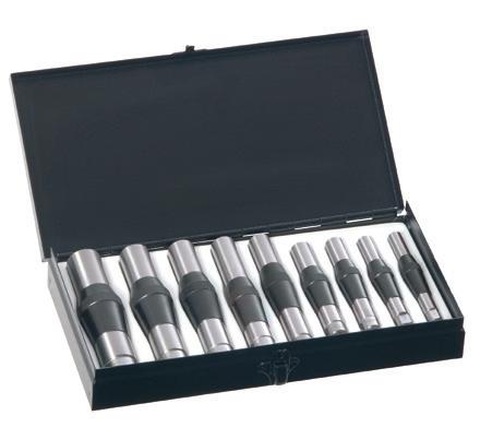
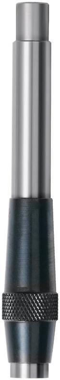
155 1200 MA 12.00–13.50 15/32–17/32 R111 1200 R112 1200 1350 MB 13.50–15.00 17/32–19/32 R111 1350 R112 1350 1500 MC 15.00–16.75 19/32–21/32 R111 1500 R112 1500 1675 MD 16.75–18.25 21/32–23/32 R111 1675 R112 1675 1825 ME 18.25–19.75 23/32–25/32 R111 1825 R112 1825 1975 MF 19.75–21.50 25/32–27/32 R111 1975 R112 1975 2150 MG 21.50–23.75 27/32–15/16 R111 2150 R112 2150 2375 MH 23.75–27.00 15/16–1-1/16 R111 2375 R112 2375 2700 MI 27.00–30.25 1-1/16–1-3/16 R111 2700 R112 2700 3025 MJ 30.25–34.25 1-3/16–1-11/32 R111 3025 R112 3025 3425 MK 34.25–38.00 1-11/32–1-1/2 R111 3425 R112 3425 3800 ML 38.00–46.00 1-1/2–1-13/16 R111 3800 R112 3800 4600 MM 46.00–56.00 1-13/16–2-7/32 R112 4600 5600 MN 56.00–69.75 2-7/32–2-3/4 R112 5600 6975 MO 69.75–85.00 2-3/4–3-11/32 R112 6975 MA1 Adjustable Reamer Pilot Set Pieces MA to MI (Pilots Only) 9 R111 MA1 R111 MA1 -
-
Catalogue Code R111 R112 Discount Group B0304 B0304 Material TCA TCA Surface Finish Brt Brt Sutton Designation -Geometry Pilots Nuts Size Ref. Size Range (mm) Range (inch) Item # Item #
-
-
Section Finder Contents Index
156 Contents Index
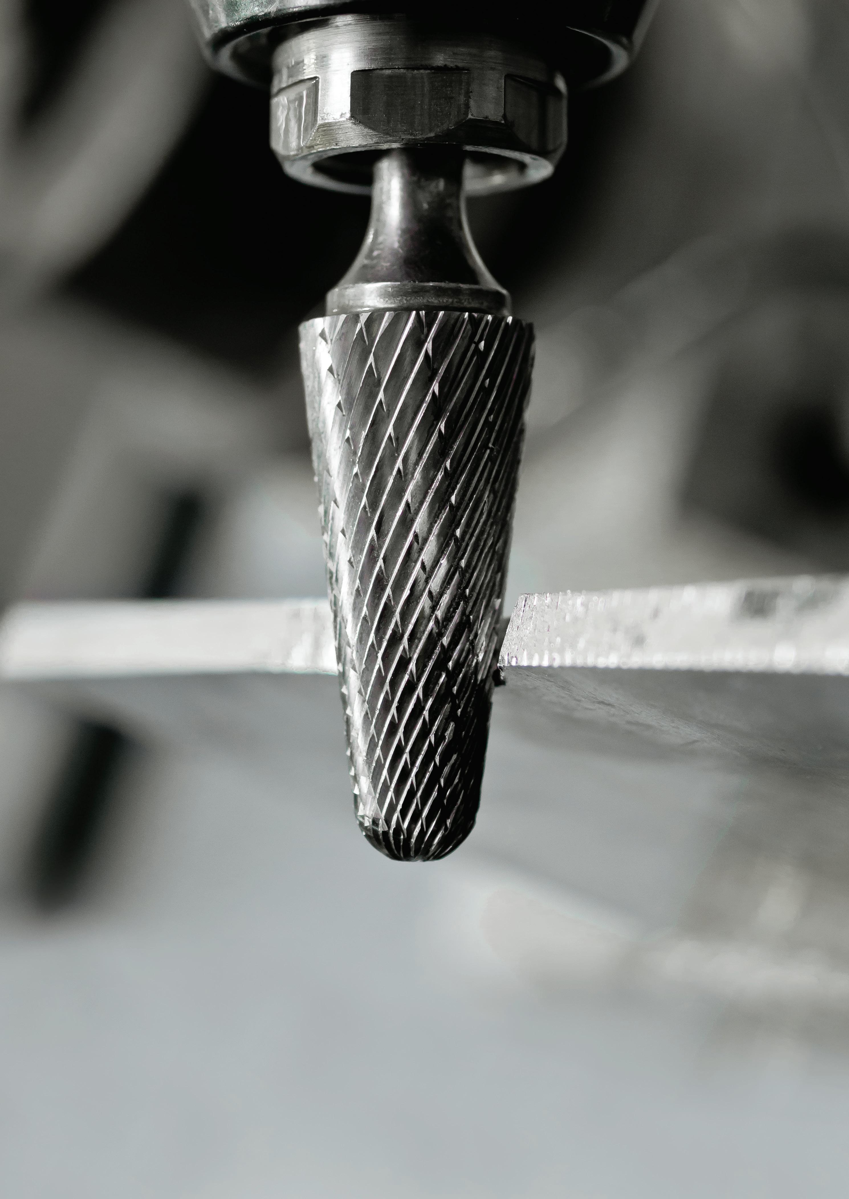
CARBIDE BURRS
• Double Cut • Aluminium Cut • Comprehensive range of shapes
• Standard & extra length available • Sets • Die Grinder Kit

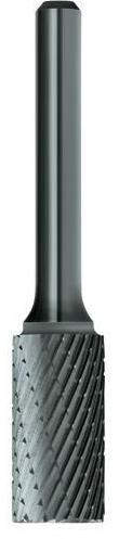
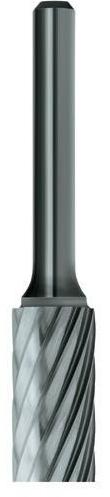
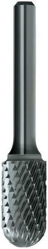

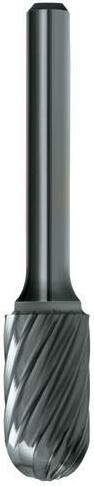
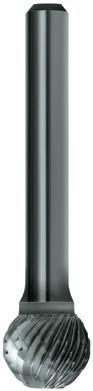
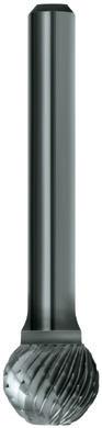
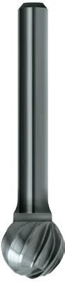
158 Carbide Burrs Finder • Optimal • Effective 1/4" 160 160 160 162 162 162 164 164 164 6mm 161 161 163 163 165 165 Catalogue Code (1/4" Shank) B200 B210 B215 B201 B211 B216 B202 B212 B217 Catalogue Code (6mm Shank) B300 B315 B301 B316 B302 B317 Material VHM VHM VHM Surface Finish Brt Brt Brt Sutton Designation Steel Aluminium Steel Aluminium Steel Aluminium Standard Sutton Standard Sutton Standard Sutton Standard Geometry Double Cut Al Cut Double Cut Al Cut Double Cut Al Cut ISO VDI^ 3323 Material Condition HB N/mm2 1 Steel - Non-alloy, cast & free cutting ~ 0.15 %C A 125 440 • • • • • • • • • P 2 ~ 0.45 %C A 190 640 • • • • • • • • • 3 QT 250 840 • • • • • • 4 ~ 0.75 %C A 270 910 • • • • • • 5 QT 300 1010 • • • • • • 6 Steel - Low alloy & cast < 5% of alloying elements A 180 610 • • • • • • • • • 7 QT 275 930 • • • • • • 8 QT 300 1010 • • • • • • 9 QT 350 1180 • • • • • • 10 Steel - High alloy, cast & tool A 200 680 • • • • • • 11 HT 325 1100 • • • • • • 12 Steel - Corrosion resistant & cast Ferritic / Martensitic A 200 680 • • • • • • 13 Martensitic QT 240 810 • • • • • • M 14.1 Stainless Steel Austenitic AH 180 610 • • • • • • 14.2 Duplex 250 840 • • • • • • 14.3 Precipitation Hardening 250 840 • • • • • • K 15 Cast Iron - Grey (GG) Ferritic / Pearlitic 180 610 • • • • • • 16 Pearlitic 260 880 • • • • • • 17 Cast Iron - Nodular (GGG) Ferritic 160 570 • • • • • • 18 Pearlitic 250 840 • • • • • • 19 Cast Iron - Malleable Ferritic 130 460 • • • • • • 20 Pearlitic 230 780 • • • • • • N 21 Aluminum & Magnesium - wrought alloy Non Heat Treatable 60 210 • • • 22 Heat Treatable AH 100 360 • • • 23 Aluminum & Magnesium - cast alloy ≤12% Si Non Heat Treatable 75 270 • • • 24 Heat Treatable AH 90 320 • • • 25 Al & Mg - cast alloy >12% Si Non Heat Treatable 130 460 • • • 26 Copper & Cu alloys (Brass/Bronze) Free cutting, Pb > 1% 110 390 • • • 27 Brass (CuZn, CuSnZn) 90 320 28 Bronze (CuSn) 100 360 • • • 29 Non-metallic - Thermosetting & fiber-reinforced plastics 30 Non-metallic - Hard rubber, wood etc. S 31 High temp. alloys Fe based A 200 680 32 AH 280 950 33 Ni / Co based A 250 840 34 AH 350 1180 35 C 320 1080 36 Titanium & Ti alloys CP Titanium 400 MPa 37.1 Alpha alloys 860 MPa 37.2 Alpha / Beta alloys A 960 MPa 37.3 AH 1170 MPa 37.4 Beta alloys A 830 MPa 37.5 AH 1400 MPa H 38.1 Hardened steel HT 45 HRC • • • • • • 38.2 HT 55 HRC • • • • • • 39.1 HT 58 HRC 39.2 HT 62 HRC 40 Cast Iron Chilled C 400 1350 • • • • • • 41 HT 55 HRC • • • • • • Condition: A (Annealed), AH (Age Hardened), C (Cast), HT (Hardened & Tempered), QT (Quenched & Tempered) ISO VDI Material Group Sutton P A Steel N UNI M R Stainless Steel VA K F Cast Iron GG N N Non-Ferrous Metals, Aluminiums & Coppers AI W S S Titaniums & Super Alloys Ti Ni H H Hard Materials (≥ 45 HRC) H ^ VDI 3323 material groups can also be determined by referring to the material cross reference listing in the application guide at the back of this catalogue. www.suttonhps.com Page Section Finder Contents Index
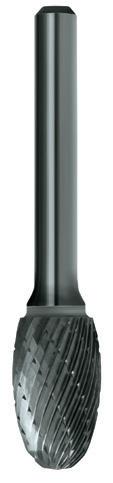
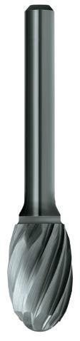
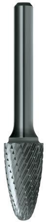
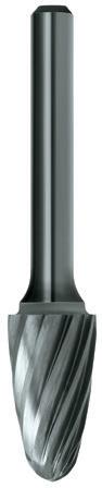
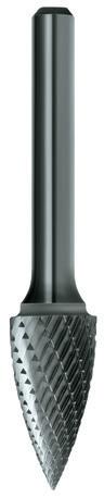
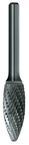
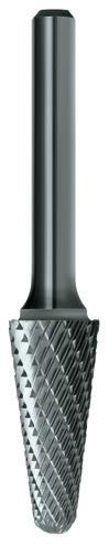
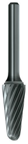
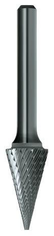
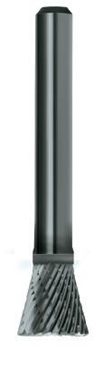
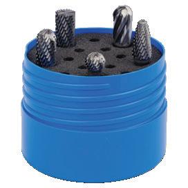
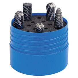
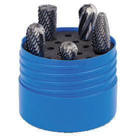
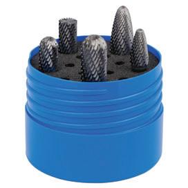
159 B900 SCB100 B900 SCB300 B900 SCB500 B900 SCB5 166 166 168 168 168 170 171 172 172 172 174 175 176 167 169 169 170 171 173 174 B203 B218 B204 B213 B219 B205 B206 B207 B214 B220 B208 B209 B303 B304 B319 B305 B306 B307 B308 VHM VHM VHM VHM VHM VHM VHM Brt Brt Brt Brt Brt Brt Brt Steel Aluminium Steel Aluminium Steel Steel Steel Aluminium Steel Steel Sutton Standard Sutton Standard Sutton Sutton Sutton Standard Sutton Sutton Double Cut Al Cut Double Cut Al Cut Double Cut Double Cut Double Cut Al Cut Double Cut Double Cut VDI^ 3323 ISO • • • • • • • • • • • • 1 P • • • • • • • • • • • • 2 • • • • • • • • • 3 • • • • • • • • • 4 • • • • • • • • • 5 • • • • • • • • • • • • 6 • • • • • • • • • 7 • • • • • • • • • 8 • • • • • • • • • 9 • • • • • • • • • 10 • • • • • • • • • 11 • • • • • • • • • 12 • • • • • • • • • 13 • • • • • • • • • 14.1 M • • • • • • • • • 14.2 • • • • • • • • • 14.3 • • • • • • • • • 15 K • • • • • • • • • 16 • • • • • • • • • 17 • • • • • • • • • 18 • • • • • • • • • 19 • • • • • • • • • 20 • • • 21 N • • • 22 • • • 23 • • • 24 • • • 25 • • • 26 27 • • • 28 29 30 31 S 32 33 34 35 36 37.1 37.2 37.3 37.4 37.5 • • • • • • • • • 38.1 H • • • • • • • • • 38.2 39.1 39.2 • • • • • • • • • 40 • • • • • • • • • 41 Section Finder Contents Index
Carbide Burrs Cylindrical, Square End
- Double Cut, for rapid stock removal in the harder materials.
- The chisel tooth pattern not only minimises tool chatter but reduces the chip to a granular shape, in most materials.
- Al Cut, for rapid stock removal of soft materials such as: Aluminium, Brass, Copper, Plastics that would normally load other cuts

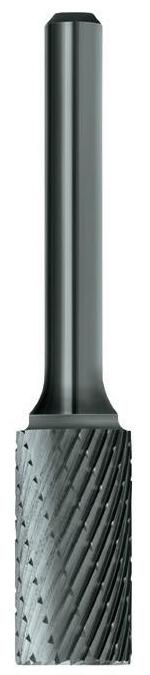
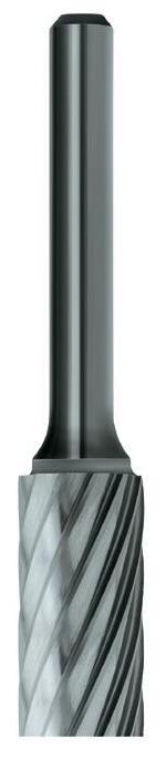
SA410 1/16 1-1/2 1/4 1/8 B200 SA410
SA420 3/32 1-1/2 7/16 1/8
SA430 1/8 1-1/2 9/16 1/8
SA510 1/4 2 3/16 1/8
SA140 3/16 2 5/8 1/4
SA100 1/4 2 5/8 1/4
SA200 5/16 2-1/2 3/4 1/4
SA300 3/8 2-1/2 3/4 1/4
SA400 7/16 2-3/4 1 1/4
SA500 1/2 2-3/4 1 1/4
SA600 5/8 2-3/4 1 1/4
SA700 3/4 2-3/4 1 1/4
SA900 1 2-3/4 1 1/4
Double Cut, Long Reach
SA3L6 3/8 6-3/4 3/4 1/4
SA5L6 1/2 7 1 1/4
Aluminium Cut
SA1AC 1/4 2 3/4 1/4
SA3AC 3/8 2-1/2 3/4 1/4
SA5AC 1/2 2-3/4 1 1/4
SA6AC 5/8 2-3/4 1 1/4
SA7AC 3/4 2-3/4 1 1/4
B200 SA420
B200 SA430
B200 SA510
B200 SA140
B200 SA100
B200 SA200
B200 SA300
B200 SA400
B200 SA500
B200 SA600
B200 SA700
B200 SA900
B210
B210 SA3L6
B210 SA5L6
B215 SA1AC
B215 SA3AC
B215 SA5AC
B215 SA6AC
B215 SA7AC
Cylindrical Square
160 160 160 160
Catalogue Code B200 B215 Discount Group B0102 B0102 Material VHM VHM Surface Finish Brt Brt Application Steel Aluminium Geometry Double Cut Al Cut Shank 1/4" 1/4" Size Ref. d1 l1 l2 d2 Item # Item # P Steel M Stainless Steel K Cast Iron N Non-Ferrous Metals S Titanium & Super Alloys H Hard Materials B215 B210 B200 VDI 3323 ISO • • • 1 P • • • 2 • • 3 • • 4 • • 5 • • • 6 • • 7 • • 8 • • 9 • • 10 • • 11 • • 12 • • 13 • • 14.1 M • • 14.2 • • 14.3 • • 15 K • • 16 • • 17 • • 18 • • 19 • • 20 • 21 N • 22 • 23 • 24 • 25 • 26 27 • 28 29 30 31 S 32 33 34 35 36 37.1 37.2 37.3 37.4 37.5 • Optimal • Effective • • 38.1 H • • 38.2 39.1 39.2 • • 40 • • 41 IMPERIAL Double Cut
Section Finder Contents Index
Carbide Burrs Cylindrical, Square End
- Double Cut, for rapid stock removal in the harder materials.
- The chisel tooth pattern not only minimises tool chatter but reduces the chip to a granular shape, in most materials.
- Al Cut, for rapid stock removal of soft materials such as: Aluminium, Brass, Copper, Plastics that would normally load other cuts
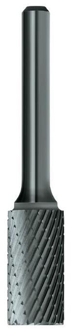
Cylindrical Square
161 161 161
Catalogue Code B300 B315 Discount Group B0102 B0102 Material VHM VHM Surface Finish Brt Brt Application Steel Aluminium Geometry Double Cut Al Cut Shank 6mm 6mm Size Ref. d1 l1 l2 d2 Item # Item #
P Steel M Stainless Steel K Cast Iron N Non-Ferrous Metals S Titanium & Super Alloys H Hard Materials B315 B300 VDI 3323 ISO • • 1 P • • 2 • 3 • 4 • 5 • • 6 • 7 • 8 • 9 • 10 • 11 • 12 • 13 • 14.1 M • 14.2 • 14.3 • 15 K • 16 • 17 • 18 • 19 • 20 • 21 N • 22 • 23 • 24 • 25 • 26 27 • 28 29 30 31 S 32 33 34 35 36 37.1 37.2 37.3 37.4 37.5 • Optimal • Effective • 38.1 H • 38.2 39.1 39.2 • 40 • 41 METRIC Double Cut SA140 4.8 51.0 15.9 6.0 B300 SA140 SA100 6.0 51.0 15.9 6.0 B300 SA100 SA200 7.9 64.0 19.1 6.0 B300 SA200 SA300 9.5 64.0 19.1 6.0 B300 SA300 SA500 13.0 70.0 25.4 6.0 B300 SA500 SA600 15.9 70.0 25.4 6.0 B300 SA600 Aluminium Cut SA3AC 9.5 64.0 19.1 6.0 B315 SA3AC
Section Finder Contents Index
Carbide Burrs Cylindrical, Radius End
- Double Cut, for rapid stock removal in the harder materials.
- The chisel tooth pattern not only minimises tool chatter but reduces the chip to a granular shape, in most materials.
- Al Cut, for rapid stock removal of soft materials such as: Aluminium, Brass, Copper, Plastics that would normally load other cuts
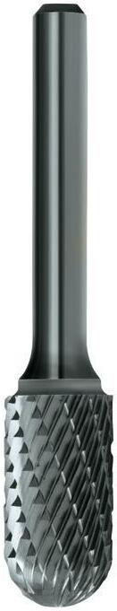
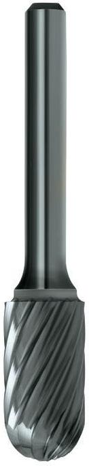
SC410 3/32 1-1/2 1/2 1/8 B201 SC410
SC420 1/8 1-1/2 1/2 1/8
SC510 1/4 2 1/2 1/8
SC120 1/8 2 1/2 1/4
SC140 3/16 2 5/8 1/4
SC100 1/4 2 5/8 1/4
SC200 5/16 2-1/2 3/4 1/4
SC300 3/8 2-1/2 3/4 1/4
SC400 7/16 2-3/4 1 1/4
SC500 1/2 2-3/4 1 1/4
SC600 5/8 2-3/4 1 1/4
SC700 3/4 2-3/4 1 1/4
Double Cut, Long Reach
SC3L6 3/8 6-3/4 3/4 1/4
SC5L6 1/2 7 1 1/4
Aluminium Cut
SC1AC 1/4 2 5/8 1/4
SC3AC 3/8 2-1/2 3/4 1/4
SC5AC 1/2 2-3/4 1 1/4
SC7AC 3/4 2-3/4 1 1/4
Cylindrical Square
B201 SC420
B201 SC510
B201 SC120
B201 SC140
B201 SC100
B201 SC200
B201 SC300
B201 SC400
B201 SC500
B201 SC600
B201 SC700
B211
B211 SC3L6
B211 SC5L6
B216 SC1AC
B216 SC3AC
B216 SC5AC
B216 SC7AC
Cylindrical Round
162 162 162 162
Catalogue Code B201 B216 Discount Group B0102 B0102 Material VHM VHM Surface Finish Brt Brt Application Steel Aluminium Geometry Double Cut Al Cut Shank 1/4" 1/4" Size Ref. d1 l1 l2 d2 Item # Item # P Steel M Stainless Steel K Cast Iron N Non-Ferrous Metals S Titanium & Super Alloys H Hard Materials B216 B211 B201 VDI 3323 ISO • • • 1 P • • • 2 • • 3 • • 4 • • 5 • • • 6 • • 7 • • 8 • • 9 • • 10 • • 11 • • 12 • • 13 • • 14.1 M • • 14.2 • • 14.3 • • 15 K • • 16 • • 17 • • 18 • • 19 • • 20 • 21 N • 22 • 23 • 24 • 25 • 26 27 • 28 29 30 31 S 32 33 34 35 36 37.1 37.2 37.3 37.4 37.5 • Optimal • Effective • • 38.1 H • • 38.2 39.1 39.2 • • 40 • • 41 IMPERIAL Double Cut
Section Finder Contents Index
Carbide Burrs Cylindrical, Radius End
- Double Cut, for rapid stock removal in the harder materials.
- The chisel tooth pattern not only minimises tool chatter but reduces the chip to a granular shape, in most materials.
- Al Cut, for rapid stock removal of soft materials such as: Aluminium, Brass, Copper, Plastics that would normally load other cuts
Cylindrical Square
163 163 163
Catalogue Code B301 B316 Discount Group B0102 B0102 Material VHM VHM Surface Finish Brt Brt Application Steel Aluminium Geometry Double Cut Al Cut Shank 6mm 6mm Size Ref. d1 l1 l2 d2 Item # Item # P Steel M Stainless Steel K Cast Iron N Non-Ferrous Metals S Titanium & Super Alloys H Hard Materials B316 B301 VDI 3323 ISO • • 1 P • • 2 • 3 • 4 • 5 • • 6 • 7 • 8 • 9 • 10 • 11 • 12 • 13 • 14.1 M • 14.2 • 14.3 • 15 K • 16 • 17 • 18 • 19 • 20 • 21 N • 22 • 23 • 24 • 25 • 26 27 • 28 29 30 31 S 32 33 34 35 36 37.1 37.2 37.3 37.4 37.5 • Optimal • Effective • 38.1 H • 38.2 39.1 39.2 • 40 • 41 METRIC Double Cut SC100 6.0 51.0 15.9 6.0 B301 SC100 SC200 7.9 64.0 19.1 6.0 B301 SC200 SC300 9.5 64.0 19.1 6.0 B301 SC300 SC400 11.1 70.0 25.4 6.0 B301 SC400 SC500 12.7 70.0 25.4 6.0 B301 SC500 SC600 15.9 70.0 25.4 6.0 B301 SC600 Aluminium Cut SC3AC 9.5 64.0 19.1 6.0
SC3AC SC5AC 12.7 70.0 25.4 6.0
SC5AC
B316
B316
Cylindrical Round
*Not available once current stock is depleted Section Finder Contents Index
Carbide Burrs Ball Shape
- Double Cut, for rapid stock removal in the harder materials.
- The chisel tooth pattern not only minimises tool chatter but reduces the chip to a granular shape, in most materials.
- Al Cut, for rapid stock removal of soft materials such as: Aluminium, Brass, Copper, Plastics that would normally load other cuts
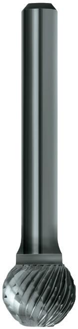
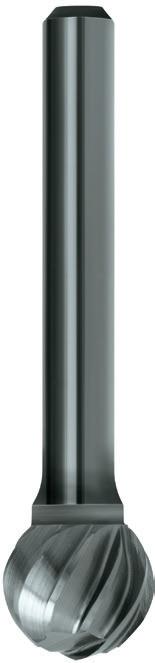
IMPERIAL
SD410 3/32 1-1/2 1/8 B202 SD410 SD420 1/8 1-1/2 1/8 B202 SD420 SD510 1/4 1-3/4 1/8
SD510 SD110 1/8 2 1/4
SD140 3/16 2 1/4 B202 SD140
SD100 1/4 2 1/4
SD200 5/16 2-1/16 1/4
SD300 3/8 2-1/16 1/4
SD400 7/16 2-1/8 1/4
SD500 1/2 2-3/16 1/4
SD600 5/8 2-5/16 1/4
SD700 3/4 2-7/16 1/4
SD900 1 2-3/4 1/4
Double
Cut, Long Reach
SD3L6 3/8 6-3/4 1/4
SD5L6 1/2 6-1/2 1/4
Aluminium Cut
SD1AC 1/4 2 1/4
SD3AC 3/8 2-1/16 1/4
SD5AC 1/2 2-3/16 1/4
SD6AC 5/8 2-5/16 1/4
SD7AC 3/4 2-7/16 1/4
B202 SD100
B202 SD200
B202 SD300
B202 SD400
B202 SD500
B202 SD600
B202 SD700
B202 SD900
B212
B212 SD3L6
B212 SD5L6
B217 SD1AC
B217 SD3AC
Cylindrical Square
B217 SD5AC
B217 SD6AC
B217 SD7AC
164 164 164 164
Catalogue Code B202 B217 Discount Group B0102 B0102 Material VHM VHM Surface Finish Brt Brt Application Steel Aluminium Geometry Double Cut Al Cut Shank 1/4" 1/4" Size Ref. d1 l1 l2 d2 Item # Item # P Steel M Stainless Steel K Cast Iron N Non-Ferrous Metals S Titanium & Super Alloys H Hard Materials B217 B212 B202 VDI 3323 ISO • • • 1 P • • • 2 • • 3 • • 4 • • 5 • • • 6 • • 7 • • 8 • • 9 • • 10 • • 11 • • 12 • • 13 • • 14.1 M • • 14.2 • • 14.3 • • 15 K • • 16 • • 17 • • 18 • • 19 • • 20 • 21 N • 22 • 23 • 24 • 25 • 26 27 • 28 29 30 31 S 32 33 34 35 36 37.1 37.2 37.3 37.4 37.5 • Optimal • Effective • • 38.1 H • • 38.2 39.1 39.2 • • 40 • • 41
Double Cut
B202
B202 SD110
Ball Shape
Section Finder Contents Index
Carbide Burrs Ball Shape
- Double Cut, for rapid stock removal in the harder materials.
- The chisel tooth pattern not only minimises tool chatter but reduces the chip to a granular shape, in most materials.
- Al Cut, for rapid stock removal of soft materials such as: Aluminium, Brass, Copper, Plastics that would normally load other cuts
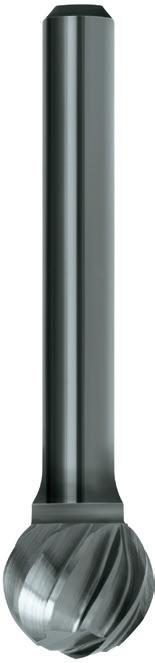
165 165 165
Catalogue Code B302 B317 Discount Group B0102 B0102 Material VHM VHM Surface Finish Brt Brt Application Steel Aluminium Geometry Double Cut Al Cut Shank 6mm 6mm Size Ref. d1 l1 l2 d2 Item # Item # P Steel M Stainless Steel K Cast Iron N Non-Ferrous Metals S Titanium & Super Alloys H Hard Materials B317 B302 VDI 3323 ISO • • 1 P • • 2 • 3 • 4 • 5 • • 6 • 7 • 8 • 9 • 10 • 11 • 12 • 13 • 14.1 M • 14.2 • 14.3 • 15 K • 16 • 17 • 18 • 19 • 20 • 21 N • 22 • 23 • 24 • 25 • 26 27 • 28 29 30 31 S 32 33 34 35 36 37.1 37.2 37.3 37.4 37.5 • Optimal • Effective • 38.1 H • 38.2 39.1 39.2 • 40 • 41 METRIC Double Cut SD140 4.5 51.0 6.4 6.0 B302 SD140 SD100 6.0 51.0 5.6 6.0 B302 SD100 SD300 9.5 52.0 7.9 6.0 B302 SD300 SD500 12.7 56.0 11.1 6.0 B302 SD500 Aluminium Cut SD3AC 9.5 52.0 7.9 6.0 B317 SD3AC
Ball Shape
Section Finder Contents Index
Cylindrical Square
Carbide Burrs Oval Shape
- Double Cut, for rapid stock removal in the harder materials.
- The chisel tooth pattern not only minimises tool chatter but reduces the chip to a granular shape, in most materials.
- Al Cut, for rapid stock removal of soft materials such as: Aluminium, Brass, Copper, Plastics that would normally load other cuts
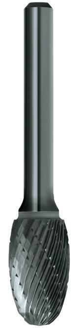
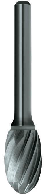
1/4 2-1/8 3/8 1/8
1/4 2 3/8 1/4
3/8 2-11/32 19/32 1/4
SE300 SE500 1/2 2-5/8 7/8 1/4
SE500 SE600 5/8 2-3/4 1 1/4 B203 SE600 SE700 3/4 2-3/4 1 1/4 B203 SE700
SE3AC 3/8 2-11/32 19/32 1/4
SE5AC 1/2 2-5/8 7/8 1/4
SE6AC 5/8 2-3/4 1 1/4
Cylindrical Square
B218 SE3AC
B218 SE5AC
B218 SE6AC
Cylindrical Round
Oval Shape Ball Shape
166 166 166
Catalogue Code B203 B218 Discount Group B0102 B0102 Material VHM VHM Surface Finish Brt Brt Application Steel Aluminium Geometry Double Cut Al Cut Shank 1/4" 1/4" Size Ref. d1 l1 l2 d2 Item # Item # P Steel M Stainless Steel K Cast Iron N Non-Ferrous Metals S Titanium & Super Alloys H Hard Materials B218 B203 VDI 3323 ISO • • 1 P • • 2 • 3 • 4 • 5 • • 6 • 7 • 8 • 9 • 10 • 11 • 12 • 13 • 14.1 M • 14.2 • 14.3 • 15 K • 16 • 17 • 18 • 19 • 20 • 21 N • 22 • 23 • 24 • 25 • 26 27 • 28 29 30 31 S 32 33 34 35 36 37.1 37.2 37.3 37.4 37.5 • Optimal • Effective • 38.1 H • 38.2 39.1 39.2 • 40 • 41 IMPERIAL Double Cut SE410
B203 SE410 SE510
B203
SE100
B203
SE300
B203
Aluminium Cut
1/8 1-1/2 7/32 1/8
SE510
SE100
B203
Section Finder Contents Index
Carbide Burrs Oval Shape
- Double Cut, for rapid stock removal in the harder materials.
- The chisel tooth pattern not only minimises tool chatter but reduces the chip to a granular shape, in most materials.
Cylindrical Square
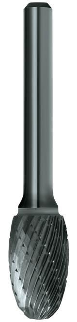
Catalogue Code B303
Discount Group
Surface
Cylindrical Round
167 167
VHM
B0102 Material
Brt
Steel
Double Cut Shank 6mm Size Ref. d1 l1 l2 d2 Item # P Steel M Stainless Steel K Cast Iron N Non-Ferrous Metals S Titanium & Super Alloys H Hard Materials B303 VDI 3323 ISO • 1 P • 2 • 3 • 4 • 5 • 6 • 7 • 8 • 9 • 10 • 11 • 12 • 13 • 14.1 M • 14.2 • 14.3 • 15 K • 16 • 17 • 18 • 19 • 20 21 N 22 23 24 25 26 27 28 29 30 31 S 32 33 34 35 36 37.1 37.2 37.3 37.4 37.5 • Optimal • Effective • 38.1 H • 38.2 39.1 39.2 • 40 • 41 METRIC Double Cut SE100 6.0 51.0 9.5 6.0 B303 SE100 SE300 9.5 60.0 15.1 6.0 B303 SE300 SE500 12.7 67.0 22.2 6.0 B303 SE500 SE600 15.9 70.0 25.4 6.0 B303 SE600
Finish
Application
Geometry
Oval Shape
Ball Shape
Section Finder Contents Index
Carbide Burrs Tree Shape, Radius End
- Double Cut, for rapid stock removal in the harder materials.
- The chisel tooth pattern not only minimises tool chatter but reduces the chip to a granular shape, in most materials.
- Al Cut, for rapid stock removal of soft materials such as: Aluminium, Brass, Copper, Plastics that would normally load other cuts
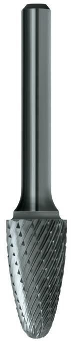
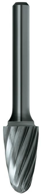
SF410 1/8 1-1/2 1/4 1/8 B204 SF410 SF420 1/8 1-1/2 1/2 1/8 B204 SF420
SF510 1/4 2 1/2 1/8 B204 SF510
SF100 1/4 2 5/8 1/4 B204 SF100
SF300 3/8 2-1/2 3/4 1/4
B204 SF300
SF400 7/16 2-3/4 1 1/4 B204 SF400
SF500 1/2 2-3/4 1 1/4
Cylindrical Square
B204 SF500
SF600 5/8 2-3/4 1 1/4 B204 SF600
SF700 3/4 2-3/4 1 1/4
SF140 3/4 2-3/4 1 -1/4 1/4
SF150 3/4 3-1/4 1 -1/2 1/4
Double Cut, Long Reach
SF3L6 3/8 6-3/4 3/4 1/4
SF5L6 1/2 7 1 1/4
Aluminium Cut
SF1AC 1/4 2 3/4 1/4
SF3AC 3/8 2-1/2 3/4 1/4
SF5AC 1/2 2-3/4 1 1/4
SF6AC 5/8 2-3/4 1 1/4
B204 SF700
B204 SF140
B204 SF150
B213
B213 SF3L6
B213 SF5L6
B219 SF1AC
B219 SF3AC
B219 SF5AC
B219 SF6AC
Tree Shape Radius Ball Shape
168 168 168 168
Catalogue Code B204 B219 Discount Group B0102 B0102 Material VHM VHM Surface Finish Brt Brt Application Steel Aluminium Geometry Double Cut Al Cut Shank 1/4" 1/4" Size Ref. d1 l1 l2 d2 Item # Item # P Steel M Stainless Steel K Cast Iron N Non-Ferrous Metals S Titanium & Super Alloys H Hard Materials B219 B213 B204 VDI 3323 ISO • • • 1 P • • • 2 • • 3 • • 4 • • 5 • • • 6 • • 7 • • 8 • • 9 • • 10 • • 11 • • 12 • • 13 • • 14.1 M • • 14.2 • • 14.3 • • 15 K • • 16 • • 17 • • 18 • • 19 • • 20 • 21 N • 22 • 23 • 24 • 25 • 26 27 • 28 29 30 31 S 32 33 34 35 36 37.1 37.2 37.3 37.4 37.5 • Optimal • Effective • • 38.1 H • • 38.2 39.1 39.2 • • 40 • • 41
Double Cut
IMPERIAL
Section Finder Contents Index
Carbide Burrs Tree Shape, Radius End
- Double Cut, for rapid stock removal in the harder materials.
- The chisel tooth pattern not only minimises tool chatter but reduces the chip to a granular shape, in most materials.
- Al Cut, for rapid stock removal of soft materials such as: Aluminium, Brass, Copper, Plastics that would normally load other cuts
Cylindrical Square
Shape
Shape Radius
169 169 169
Catalogue Code B304 B319 Discount Group B0102 B0102 Material VHM VHM Surface Finish Brt Brt Application Steel Aluminium Geometry Double Cut Al Cut Shank 6mm 6mm Size Ref. d1 l1 l2 d2 Item # Item # P Steel M Stainless Steel K Cast Iron N Non-Ferrous Metals S Titanium & Super Alloys H Hard Materials B319 B304 VDI 3323 ISO • • 1 P • • 2 • 3 • 4 • 5 • • 6 • 7 • 8 • 9 • 10 • 11 • 12 • 13 • 14.1 M • 14.2 • 14.3 • 15 K • 16 • 17 • 18 • 19 • 20 • 21 N • 22 • 23 • 24 • 25 • 26 27 • 28 29 30 31 S 32 33 34 35 36 37.1 37.2 37.3 37.4 37.5 • Optimal • Effective • 38.1 H • 38.2 39.1 39.2 • 40 • 41 METRIC Double Cut SF100 6.0 51.0 15.9 6.0 B304 SF100 SF300 9.5 64.0 19.1 6.0 B304 SF300 SF400 11.1 70.0 25.4 6.0 B304 SF400 SF500 12.7 70.0 25.4 6.0 B304 SF500 Aluminium Cut SF3AC 9.5 64.0 19.1 6.0 B319 SF3AC SF5AC 12.7 70.0 25.4 6.0 B319 SF5AC SF6AC 15.9 70.0 25.4 6.0
SF6AC Tree
Ball
B319
Section Finder Contents Index
Carbide Burrs Tree Shape, Pointed End
- Double Cut, for rapid stock removal in the harder materials.
- The chisel tooth pattern not only minimises tool chatter but reduces the chip to a granular shape, in most materials.
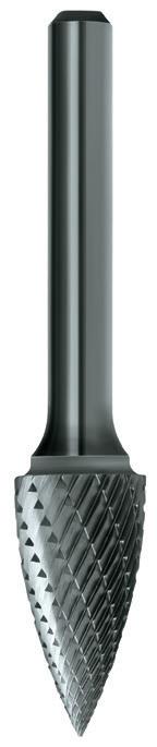

SG410 1/8 1-1/2 1/4 1/8
1/8 1-1/2 3/8 1/8
1/4 2 1/2 1/8
SG510 SG100 1/4 2 5/8 1/4 B205 SG100
SG200 5/16 2-1/2 3/4 1/4 B205 SG200
SG300 3/8 2-1/2 3/4 1/4 B205 SG300
SG130 1/2 2-1/2 3/4 1/4 B205 SG130
SG500 1/2 2-3/4 1 1/4 B205 SG500
SG600 5/8 2-3/4 1 1/4
SG700 3/4 2-3/4 1 1/4
B205 SG600
B205 SG700
SG150 3/4 2-3/4 1-1/2 1/4 B205 SG150
METRIC
Double Cut
7.9 64.0 19.1 6.0
SG100
SG200 SG300 9.5 64.0 19.1 6.0 B305 SG300
SG130 12.7 64.0 19.1 6.0
SG500 12.7 70.0 25.4 6.0
B305 SG130
B305 SG500
170 170 170
B205 B305 Discount Group B0102 B0102 Material VHM VHM Surface Finish Brt Brt Application Steel Steel Geometry Double Cut Double Cut Shank 1/4" 6mm Size Ref. d1 l1 l2 d2 Item # Item # P Steel M Stainless Steel K Cast Iron N Non-Ferrous Metals S Titanium & Super Alloys H Hard Materials B305 B205 VDI 3323 ISO • • 1 P • • 2 • • 3 • • 4 • • 5 • • 6 • • 7 • • 8 • • 9 • • 10 • • 11 • • 12 • • 13 • • 14.1 M • • 14.2 • • 14.3 • • 15 K • • 16 • • 17 • • 18 • • 19 • • 20 21 N 22 23 24 25 26 27 28 29 30 31 S 32 33 34 35 36 37.1 37.2 37.3 37.4 37.5 • Optimal • Effective • • 38.1 H • • 38.2 39.1 39.2 • • 40 • • 41
Double Cut
Catalogue Code
IMPERIAL
B205 SG410 SG430
B205
SG510
B205
SG430
B305
SG100 6.0 51.0 15.9 6.0
SG200
B305
Tree Shape Pointed
Tree Shape Radius
Oval Shape
Ball Shape
Cylindrical Round
Section Finder Contents Index
Cylindrical Square
Carbide Burrs Flame Shape
- Double Cut, for rapid stock removal in the harder materials.
- The chisel tooth pattern not only minimises tool chatter but reduces the chip to a granular shape, in most materials.

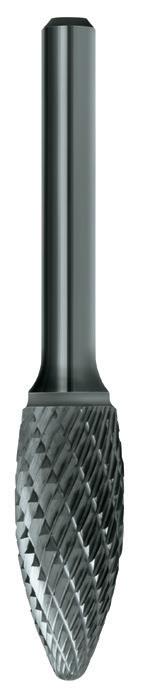
171 171 171
Catalogue Code B206 B306 Discount Group B0102 B0102 Material VHM VHM Surface Finish Brt Brt Application Steel Steel Geometry Double Cut Double Cut Shank 1/4 6mm Size Ref. d1 l1 l2 d2 Item # Item #
P Steel M Stainless Steel K Cast Iron N Non-Ferrous Metals S Titanium & Super Alloys H Hard Materials B306 B206 VDI 3323 ISO • • 1 P • • 2 • • 3 • • 4 • • 5 • • 6 • • 7 • • 8 • • 9 • • 10 • • 11 • • 12 • • 13 • • 14.1 M • • 14.2 • • 14.3 • • 15 K • • 16 • • 17 • • 18 • • 19 • • 20 21 N 22 23 24 25 26 27 28 29 30 31 S 32 33 34 35 36 37.1 37.2 37.3 37.4 37.5 • Optimal • Effective • • 38.1 H • • 38.2 39.1 39.2 • • 40 • • 41 IMPERIAL Double Cut SH410 1/8 1-1/2 1/4 1/8 B206 SH410 SH100 1/4 2 5/8 1/4 B206 SH100 SH200 5/16 2-1/2 3/4 1/4 B206 SH200 SH500 1/2 3 1 -1/4 1/4 B206 SH500 SH600 5/8 3-3/16 1 -7/16 1/4 B206 SH600 SH700 3/4 3-3/8 1 -5/8 1/4 B206 SH700 METRIC Double Cut SH200 7.9 64.0 19.1 6.0 B306 SH200 SH500 12.7 70.0 25.4 6.0 B306 SH500 SH600 15.9 70.0 25.4 6.0
SH600 Flame Shape Tree Shape Radius Ball
Section Finder Contents Index
B306
Shape Cylindrical Square
Carbide Burrs Taper Shape
- Double Cut, for rapid stock removal in the harder materials.
- The chisel tooth pattern not only minimises tool chatter but reduces the chip to a granular shape, in most materials.
- Al Cut, for rapid stock removal of soft materials such as: Aluminium, Brass, Copper, Plastics that would normally load other cuts
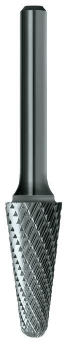
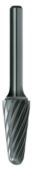
172 172 172 172
Catalogue Code B207 B220 Discount Group B0102 B0102 Material VHM VHM Surface Finish Brt Brt Application Steel Aluminium Geometry Double Cut Al Cut Shank 1/4" 1/4" Size Ref. d1 l1 l2 d2 Rad Item # Item #
P Steel M Stainless Steel K Cast Iron N Non-Ferrous Metals S Titanium & Super Alloys H Hard Materials B220 B214 B207 VDI 3323 ISO • • • 1 P • • • 2 • • 3 • • 4 • • 5 • • • 6 • • 7 • • 8 • • 9 • • 10 • • 11 • • 12 • • 13 • • 14.1 M • • 14.2 • • 14.3 • • 15 K • • 16 • • 17 • • 18 • • 19 • • 20 • 21 N • 22 • 23 • 24 • 25 • 26 27 • 28 29 30 31 S 32 33 34 35 36 37.1 37.2 37.3 37.4 37.5 • Optimal • Effective • • 38.1 H • • 38.2 39.1 39.2 • • 40 • • 41 IMPERIAL Double Cut SL410 1/8 1-1/2 3/8 1/8 6 B207 SL410 SL420 1/8 1-1/2 1/2 1/8 7 B207 SL420 SL100 1/4 2 5/8 1/4 14 B207 SL100 SL200 5/16 2-5/8 7/8 1/4 14 B207 SL200 SL300 3/8 2-13/16 1 -1/16 1/4 14 B207 SL300 SL400 1/2 2-7/8 1 -1/8 1/4 14 B207 SL400 SL600 5/8 3-1/16 1 -5/16 1/4 14 B207 SL600 SL700
1 -1/2
14 B207 SL700 Double
B214 SL3L6
7-1/16 1 -1/16 1/4 14 B214 SL3L6 Aluminium
SL4AC 1/2 2-7/8 1-1/8 1/4 14 B220 SL4AC SL6AC 5/8 3-1/16 1-5/16 1/4 14 B220 SL6AC SL7AC
14 B220 SL7AC Taper
Flame
Tree
Tree
Oval
Ball
Cylindrical
Cylindrical
Section Finder Contents Index
3/4 3-1/4
1/4
Cut, Long Reach
3/8
Cut
3/4 3-1/4 1-1/2 1/4
Shape
Shape
Shape Pointed
Shape Radius
Shape
Shape
Round
Square
Carbide Burrs Taper Shape
- Double Cut, for rapid stock removal in the harder materials.
- The chisel tooth pattern not only minimises tool chatter but reduces the chip to a granular shape, in most materials.
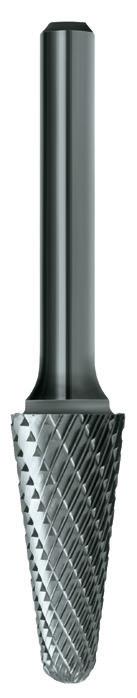
Catalogue Code B307
Discount Group
Surface
173 173
Material VHM
B0102
Finish Brt Application Steel Geometry Double Cut Shank 6mm Size Ref. d1 l1 l2 d2 Rad Item #
P Steel M Stainless Steel K Cast Iron N Non-Ferrous Metals S Titanium & Super Alloys H Hard Materials B307 VDI 3323 ISO • 1 P • 2 • 3 • 4 • 5 • 6 • 7 • 8 • 9 • 10 • 11 • 12 • 13 • 14.1 M • 14.2 • 14.3 • 15 K • 16 • 17 • 18 • 19 • 20 21 N 22 23 24 25 26 27 28 29 30 31 S 32 33 34 35 36 37.1 37.2 37.3 37.4 37.5 • Optimal • Effective • 38.1 H • 38.2 39.1 39.2 • 40 • 41 METRIC Double Cut SL100 6.0 51.0 15.9 6.0 14 B307 SL100 SL200 7.9 67.0 22.2 6.0 14 B307 SL200 SL300 9.5 71.0 27.0 6.0 14 B307 SL300 SL400 12.7 73.0 28.6 6.0 14 B307 SL400 SL600 15.9 78.0 33.3 6.0 14 B307 SL600 Taper Shape Flame Shape Tree Shape Pointed Tree
Radius Oval Shape Ball
Round
Section Finder Contents Index
Shape
Shape Cylindrical
Cylindrical Square
Carbide Burrs Cone Shape
- Double Cut, for rapid stock removal in the harder materials.
- The chisel tooth pattern not only minimises tool chatter but reduces the chip to a granular shape, in most materials.
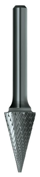
METRIC
174 174 174
Catalogue Code B208 B308 Discount Group B0102 B0102 Material VHM VHM Surface Finish Brt Brt Application Steel Steel Geometry Double Cut Double Cut Shank 1/4" 6mm Size Ref. d1 l1 l2 d2 Angle Item # Item #
P Steel M Stainless Steel K Cast Iron N Non-Ferrous Metals S Titanium & Super Alloys H Hard Materials B308 B208 VDI 3323 ISO • • 1 P • • 2 • • 3 • • 4 • • 5 • • 6 • • 7 • • 8 • • 9 • • 10 • • 11 • • 12 • • 13 • • 14.1 M • • 14.2 • • 14.3 • • 15 K • • 16 • • 17 • • 18 • • 19 • • 20 21 N 22 23 24 25 26 27 28 29 30 31 S 32 33 34 35 36 37.1 37.2 37.3 37.4 37.5 • Optimal • Effective • • 38.1 H • • 38.2 39.1 39.2 • • 40 • • 41 IMPERIAL Double Cut SM420 1/8 1-1/2 1/2 1/8 12° B208 SM420 SM430 1/8 1-1/2 5/8 1/8 9° B208 SM430 SM510 1/4 2 1/2 1/8 22° B208 SM510 SM100 1/4 2 1/2 1/4 22° B208 SM100 SM200 1/4 2 3/4 1/4 14° B208 SM200 SM300 1/4 2 1 1/4 12° B208 SM300 SM400 3/8 2-1/2 3/4 1/4 28° B208 SM400 SM500 1/2 2-3/4 1 1/4 28° B208 SM500 SM600
1-1/8 1/4 31° B208 SM600
5/8 2-7/8
Double Cut SM300 6.0 51.0 25.4 6.0 12° B308 SM300 SM400 9.5 64.0 19.1 6.0 28° B308 SM400 SM500 12.7 70.0 25.4 6.0 28° B308 SM500 SM600 15.9 73.0 28.6 6.0 31° B308 SM600 Taper Flame Shape Tree Shape Tree Shape Radius Oval Shape Ball Shape Cylindrical Cylindrical Square Cone Shape Inverted Cone Section Finder Contents Index
Carbide Burrs Inverted Cone Shape
- Double Cut, for rapid stock removal in the harder materials.
- The chisel tooth pattern not only minimises tool chatter but reduces the chip to a granular shape, in most materials.
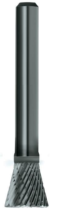
Catalogue Code
Discount
Surface
175 175
B209
Material VHM
Group B0102
Finish Brt Application Steel Geometry Double Cut Shank 1/4" Size Ref. d1 l1 l2 d2 Angle Item #
P Steel M Stainless Steel K Cast Iron N Non-Ferrous Metals S Titanium & Super Alloys H Hard Materials B209 VDI 3323 ISO • 1 P • 2 • 3 • 4 • 5 • 6 • 7 • 8 • 9 • 10 • 11 • 12 • 13 • 14.1 M • 14.2 • 14.3 • 15 K • 16 • 17 • 18 • 19 • 20 21 N 22 23 24 25 26 27 28 29 30 31 S 32 33 34 35 36 37.1 37.2 37.3 37.4 37.5 • Optimal • Effective • 38.1 H • 38.2 39.1 39.2 • 40 • 41 IMPERIAL Double Cut SN420 1/8 1-1/2 1/8 1/8 14° B209 SN420 SN510 1/4 1-3/4 1/4 1/8 10° B209 SN510 SN100 1/4 2 1/4 1/4 10° B209 SN100 SN200 3/8 2-1/8 3/8 1/4 13° B209 SN200 SN400 1/2 2-1/2 1/2 1/4 28° B209 SN400 SN600 5/8 2-1/2 3/4 1/4 18° B209 SN600 SN700 3/4 2-5/8 5/8 1/4 30° B209 SN700 Taper Shape Flame Shape Tree Shape Pointed Tree Shape Radius Oval Shape Ball Shape Cylindrical Round Cylindrical Square Cone Shape Inverted Cone Shape Section Finder Contents Index
Carbide Burrs Sets
All sets packed in ABS case (industrial grade plastic material).
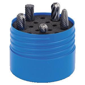
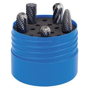
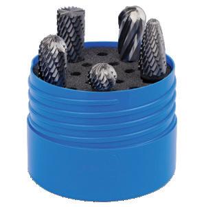
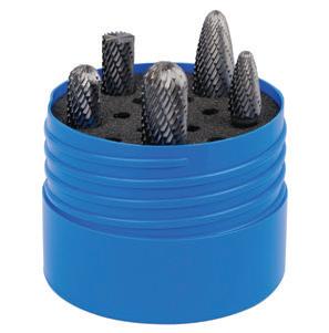
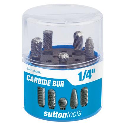
Catalogue Code B900
Discount Group B0102
Material VHM
Surface Finish Brt ApplicationGeometry
Shank 1/4"
176 176
Size Ref. Description d1 d2 Pieces Item #
-
B900 SCB100
B900 SCB100
Type Cyl/Sq Cyl/Rad Ball Tree/Rad Cyl/Sq -Al SCB100 SA100 SC100 SD100 SF100 SC1AC 1/4 1/4 5 B900 SCB100 SCB300
3/8 1/4 5 B900 SCB300 SCB500
5 B900 SCB500
& 1/2 1/4 5 B900 SCB5 Section Finder Contents Index
B900
SCB300 B900 SCB500 B900 SCB5 Burr Sets
SA300 SC300 SD300 SF300 SC3AC
SA500 SC500 SD500 SF500 SC5AC 1/2 1/4
SCB5 SA300 SC300 SC500 SF300 SF500 3/8
Carbide Burrs Die Grinder Kit
Sutton Tools Die Grinder is the perfect tool for detailed metal or woodwork providing precise clean cuts. Use it with Sutton Tools range of carbide burrs to sculpt and shape harder materials.
Suitable for grinding back and neatening welds, porting, polishing and woodworking applications.
Features:
• Quick release attachment
• Trigger with safety latch prevent accidental operation
• Adjusting knob controls speed of rotation
Specifications:
• Collet capacity: 1/8, 1/4, 3 & 6mm
• No load speed: 25,000 RPM
• Air Pressure: 90 PSI
• Overall Length: 165mm
• Net Weight: 557g
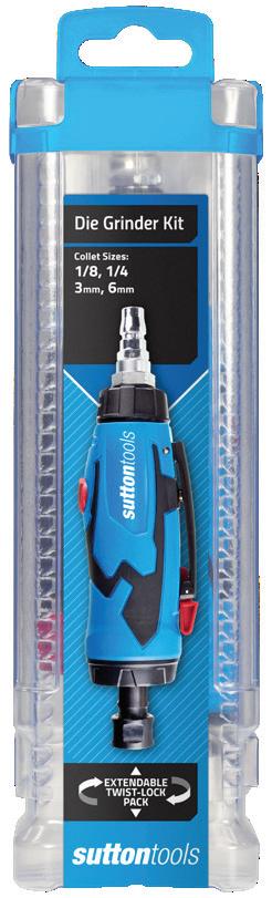
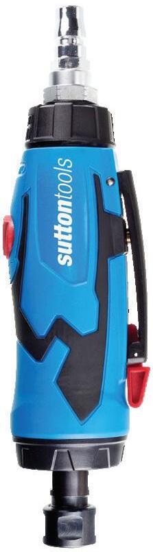
Die Grinder Kit Pneumatic Die Grinder 4 collets: 1/8, 1/4, 3 & 6mm 2 x wrenches
Note: Reduce cutting speeds by 50% when using long shank carbide burrs.
177
Description
Item #
Contents
B902
B902 0002
Recommended Cutting Speeds (RPM) – Standard Length Burrs Steels & Alloys Stainless Steel Aluminium Diameter Double Cut Double Cut Aluminium Cut Max RPM 1/16 33,000 50,000 - 78,000 3/32 26,000 40,000 - 60,000 1/8 23,000 35,000 - 53,000 3/16 17,000 25,000 - 38,000 1/4 15,000 22,000 30,000 33,000 5/16 13,000 20,000 25,000 30,000 3/8 12,000 18,000 20,000 27,000 7/16 11,500 17,000 18,000 26,000 1/2 11,000 16,000 15,000 24,000 5/8 10,000 15,000 12,000 23,000 3/4 9,000 14,000 10,000 21,000 7/8 8,500 13,000 - 20,000 1" 8,000 12,000 - 18,000
Discount Group: B0102
Section Finder Contents Index
178 Section Finder Contents Index

OTHER
• Literature • Cutting Lubricant
Other Black Books

The ultimate reference book
- Pocket sized - grease / tear proof - lay-flat format
- Ideal for engineers, trades people, apprentices, machine shops, tool rooms, technical colleges
Engineers Black Book - 234 Pages of:
Tables
• Standards
• Illustrations
• Grinding wheels
Conversion factors
Tapers
Lubricantscoolants
• Bolts and nuts
Spur gear calculations
• Tungsten carbide
• Plastics Sharpening information
G Codes
• Hardening and tempering Formulae
Geometrical construction
Weights of metal
Engineering drawing standards
• Tolerances
• Keys and keyways
Tapping drill sizes
Speeds & feeds
Equivalent charts and more…
Electrical Black Book - 212 Pages of:
Electrical safety laws of electricity electrical conductors
Electrical codes and standards
Electrical conduit and conduit bending
Electrical formulae and conversion factors transformers and motors
Electrical socket-outlets, switches and enclosures
• Led lighting, fibre optics and data cabling and more…
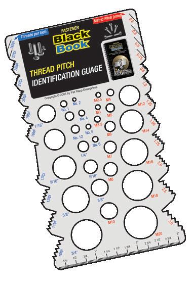
Fastener Black Book - 248 Pages of:
Screw thread fundamentals
• Standards
• Heat treatment
• Thread classes
Grades
Materials and coatings
• Failures and corrosion
Thread terminology
• Tolerances
• Fastener strengths and markings
Hydrogen embrittlement
• Screw thread profiles
Dimensional specifications
DIN / ISO / ANSI
Galling
Material selection
• Torque control
• Platings
• Elevated temperature effects
Discount Group: Z0502
180
L100 Engineers Black Book 3rd 234 40 Labelling Tabs L100V3EN L103 Engineers Black Book - Large Edition 3rd 234 20 Labelling Tabs L103V3EN L200 Fasteners Black Book 1st 248 40 Thread Pitch Gauge L200V1EN L203 Fasteners Black Book - Large Edition 1st 248 20 Thread Pitch Gauge L203V1EN L300 Electrical Black Book 2nd 212 40 Labelling Tabs L300V2EN Description Edition Pages Carton Qty Bonus Item # EDITIONLARGE EDITIONLARGE L200V1EN L203V1EN L300V2EN L100V3EN L103V3EN Contents Index
Other Cutting Lubricant, Venom
Venom Endurance+ Cutting Fluid
Venom Endurance+ Cutting Fluid is a highly efficient cutting and lubricating fluid. Formulated to increase tool life and enhance cutting performance in a broad range of metals including carbon steel, aluminium alloys, copper, brass, bronze and stainless steel. Mild clinging action helps fluid adhere to the tool and part when vertical work is required.
available in multiples of 6 **Only available in multiples of 12
Features
• Low melting point – adheres to cutting edge for greater tool protection
• Not affected by coolant
• Lowest torque required for higher performance
• Reduced friction for extremely high quality surface finish
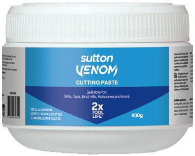
Venom Extreme Power Cutting Paste
Formulated for superior tool life and cutting performance in carbon steel, aluminium alloys, copper, bronze, stainless steel, nickels, titaniums and other super alloys.
Venom Extreme Power Cutting Paste is a high performance low melting point lubricant specifically designed to adhere to the cutting edges, even when using additional coolants.
Features
• Reduces torque and friction
• Extends tool life
• Improves surface finish
• Accurate thread quality
• Environmentally friendly mineral oil base with 10% organic coconut oil. Free from Trichloroethane – low odour.
CUTTING SPRAY
Features
• Comfort nozzle allows an accurate spray flow in hard-to-reach working areas
• Precise spray flow within 1.5m range
• Non-flammable
• Reduces torque and friction
• Extends tool life
• Improves surface finish
• Accurate thread quality
• Environmentally friendly mineral oil base with 10% organic coconut oil. Free from Trichloroethane – low odour.
• Suitable for use in non-ventilated areas

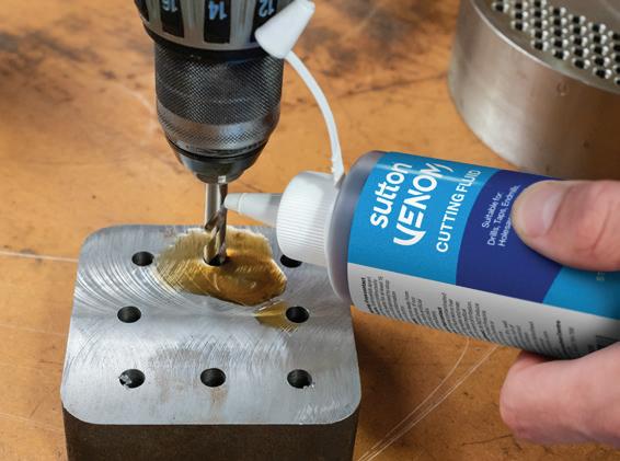
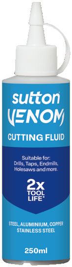
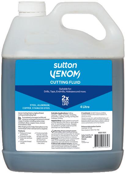
181
Discount Group Z1006 Size Ref. Description Size Item #
M800 0050 Venom Cutting Fluid** 50ml M800 0050 0250 Venom Cutting Fluid 250ml M800 0250 0300 Venom Cutting Spray* 300g M800 0300 0400 Venom Cutting Paste 400g M800 0400 4000 Venom Cutting Fluid 4L M800 4000
Tests were conducted using a M6 forming tap in carbon steel and aluminium. The results clearly indicate less torque* was required using Sutton Tools Venom Cutting Fluid & Paste compared with leading brands on the market. *Less torque indicates improved performance. Tests indicate Sutton Tools Venom requires less torque –it performed up to 30% better than its competitors Venom Competitor X Competitor Y Competitor Z Aluminium Carbon Steel TEST 1 – CUTTING PASTE 0 75 150 225 300 VENOM VENOM Torque (Ncm) Aluminium Carbon Steel TEST 2 – CUTTING FLUID 0 100 200 300 400 0 100 200 300 400 VENOM VENOM
*Only
M800 0300 M800 0400 M800 0250 M800 4000 M800 0050 Contents Index
182 Contents Index
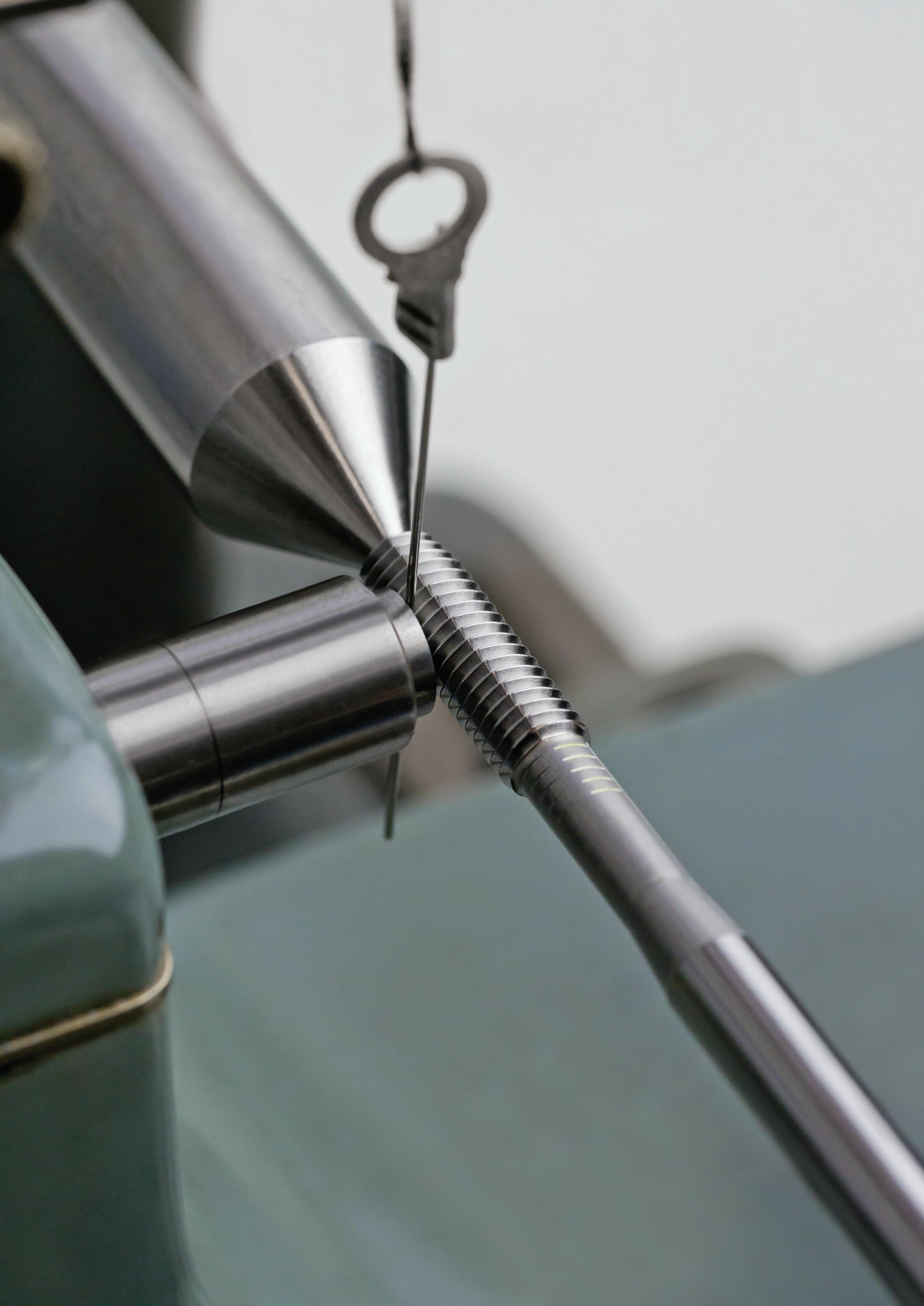
TECHNICAL
•
•
•
•
•
INFO • Speeds & Feeds Charts
Troubleshooting
General
Drills
Taps • Endmills
Reamers
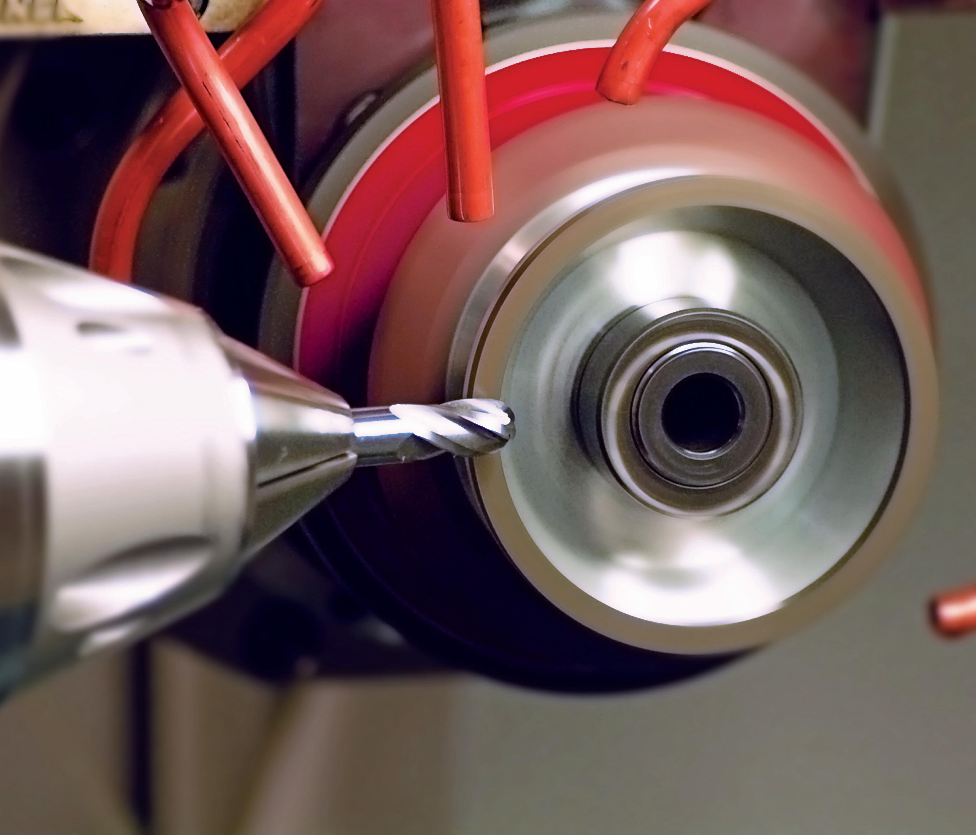
Regrinding Service… Reduce your production costs
Sutton Tools continue to reinvest to provide a ‘complete’ range in cutting tool products and services. Our regrinding service returns tools to ‘as new’ condition. Quality is guaranteed from the CNC grinding machines which are operated by highly experienced personnel, using advanced technology. A full regrinding service is offered in Europe. HSS and carbide tooling can be reconditioned by our highly experienced personnel, with reproducible, high quality results, every time.
We regrind HSS Powdered Metallurgy and grades of Solid Carbide, complemented by fifth generation thin film coatings.
Sutton Tools Recoating Service
In Europe we provide a full regrinding service for Sutton Tools distributors. Using world-leading technology, coatings are available to solve a wide range of problems relating to friction and wear, thereby improving tool performance and increasing tool life, up to 300-1000% compared to uncoated.
Send & Return Service
Sutton Tools re-sharpening boxes will be provided for safe shipment of your tools for servicing. Simply fill in the request form, and we will return the tools to ‘as new’ condition as instructed. Contact us for your Sutton Tools re-sharpening box and request form.
185 Contents Page General Coatings & Surface Finish 200 Conversion Tables - Metric/Imperial 202 Manufacturing Tolerances 204 Materials - Tool 201 Materials - Workpiece 186 Shank Designs - Carbide Tools 206 - HSS Tools 205 Tensile Strength vs Hardness (≈) 204 Drills Drill Definitions 207 Drill Point Types 207 Drill Terminology 207 Drill Tolerances 207 Hints on Use & Maintenance 208 Speeds & Feeds - HSS Drills 190 Troubleshooting - Drills 196 Taps Chamfer Type/Length 210 Construction Dimensions/Designs 210 Fluteless Taps 216 ISO Metric Tap Class & Tolerance 220 Lubricants 213 Speeds & Feeds - Taps 192 Tap Geometry 212 Tap Hole Types 211 Tap Terminology 209 Tap Types 211 Tapping Drill 213 Tapping Drill Size Chart (Fluteless) 217 Tapping Drill Formula 213 Tapping Drill Size Chart 214 Tapping Information 213 Thread Limits 219 Thread Systems - ISO Metric 218 - ISO Pipe 223 - Unified 221 - Whitworth 222 Tap Styles 210 Troubleshooting - Taps 197 Contents Page Endmills Climb & Conventional Milling 224 Endmill Terminology 224 Endmill Types 225 Speeds & Feeds - HSS Endmills 194 Troubleshooting - Endmills 198 Reamers Hints on Use 226 Tolerances 226 Troubleshooting - Reamers 199 Enquiry forms for special tools Carbide Drills 229 Endmills 230 HSS Drills 228 Taps 227 Technical Information Index Contents Index
Application Guide Materials - Workpiece
4
4
4
5
6
6
6
6
6
6
6
6
6
6
6
6
6
6
6
6
6
186 Material Group WKR DIN BS EN AFNOR UNI UNE SS JIS AISI / SAE / UNS ISO VDI^ 3323 Germany Germany U.K. U.K. France Italy Spain Sweden Japan USA P 1 1.0402 C 22 050 A 20 2C CC20 C 20 , C 21 F.112 1450 1020, G 10200 1 1.0715 9 SMn 28 230 M 07 S250 CF 9 SMn 28 11SMn28 1912 SUM 22 1213, G 12130 1 1.0722 10 SPb 20 10PbF2 CF 10 SPb 20 10SPb20 11 L 08 1 1.0736 9 SMn 36 240 M 07 1B S300 CF 9 SMn 36 12SMN35 1215, G 12150 1 1.0737 9 SMnPb 36 S300Pb CF 9 SMnPb 36 12SMnP35 1926 12 L 14, G 12144 1 1.0401 C 15 080 M 15 CS CC12 C16 F.111 1350 S 15 CK 1015, G 10170 1 1.0718 9 SMnPb 28 S250Pb CF 9 SMnPb 28 11SMnPb28 1914 SUM 22 L 12 L 13, G 12134 1 1.1141 Ck 15 080 M 15 32C XC12 , XC15 , XC18 C15 1370 S15C 1015, G 10170
1.1170 28 Mn 6 150 M 28 14A 20M5 C 28 Mn SCMn 1 1330
/ 3 1.0501 C 35 060 A 35 CC35 C 35 F.113 1550 S 35 C 1035, G 10350 2 / 3 1.0503 C 45 080 M 46 CC45 C 45 F.114 1650 S45C 1045, G 10430 2 / 3 1.1191 Ck 45 080 M 46 C 45 F.1140 1672 S48C 1045, G 10420
/ 3 1.0726 35 S 20 212 M 36 8M 35 MF 4 F.210.G 1957 1140, G 11400
/ 3 1.1157 40 Mn 4 150 M 36 15 35 M 5 1039, G10390
/ 3 1.1167 36 Mn 5 150 M 36 40 M 5 F.411 2120 SMn438(H) 1335, G 13350
/ 5 1.0535 C 55 070 M 55 C 55 F.1150 1655 S 55 C 1055
2
2
2
2
2
4
/ 5 1.0601 C 60 080 A 62 43D CC 55 C 60 S 58 C 1060, G 10600
/ 5 1.1203 Ck 55 070 M 55 XC 55 C 50 1655 S 55 C 1055
/ 5 1.1221 Ck 60 080 A 62 43D XC 60 C 60 F.1150 1665; 1678 S 58 C 1060, G 10640
4
4
/ 5 1.1545 C 105 W1 BW 1A C 100 KU F.5118 1880 SK 3 W 110, T 72301
/ 5 1.1274 Ck 101 060 A 96 F.5117 1870 SUP 4 1095, G 10950
/ 9 1.5120 38 MnSi 4
/ 7 1.6657 10 NiCrMo 13-4 832 M 13 36C 15 NiCrMo 13 14NiCrMo131
/ 7 1.5423 16 Mo 5 1503-245-420 16 Mo 5 16Mo5 SB 450 M 4520, G 45200
6
/ 7 1.7131 16 MnCr 5 527 M 17 16 MC 5 16 MnCr 5 F.1516 2511 SCR 415 5115, G 51170
/ 7 1.5622 14 Ni 6 16 N 6 14 Ni 6 15Ni6 A350LF5
/ 7 1.5415 15 Mo 3 1501-240 15 D 3 16 Mo 3 16Mo3 2912 A204GrA
/ 7 1.5752 14 NiCr 14 655 M 13 36A 12 NC 15 SNC 815 (H) 3310, 3415, 9314, G 33106
6
/ 7 1.6587 17 CrNiMo 6 820 A 16 18 NCD 6 18 NiCrMo 7
/ 7 1.7262 15 CrMo 5 12 CD 4 12 CrMo 4 12CrMo4 2216
6
/ 7 1.7335 13 CrMo 4-4 1501-620 Gr. 27 15 CD 3.5 14 CrMo 4 5 14CrMo45 2216 A 182-F11, F12
/ 7 1.7380 10 CrMo 9-10 1501-622 Gr. 31, 45 10 CD 9.10 12 CrMo 9 10 F.155 2218 A 182-F22, J 21890
/ 7 1.7715 14 MoV 6-3 1503-660-440
/ 7 1.7015 10 Cr 3 523 M 15 12 C 3 SCr 415 (H) 5015, G 50150
6
6
6
/ 8 1.7033 34 Cr 4 530 A 32 18B 32 C 4 34 Cr 4 (KB) SCr 430 (H) 5132, G 51320
/ 8 1.7218 25 CrMo 4 1717 CDS 110 25 CD 4 S 25 CrMo 4 (KB) F.1251 2225 SCM 420, SCM 430 4130, G 41300
/ 8 1.6523 21 NiCrMo 2 805 M 20 362 20 NCD 2 20 NiCrMo 2 F.1522 2506 SNCM 220 (H) 8620, G 86170
/ 9 1.7220 34 CrMo 4 708 A 37 35 CD 4 35 CrMo 4 2234 SCM 432, SCCrM 3 4135, 4137, G 41350
/ 9 1.7225 42 CrMo 4 708 M 40 42 CD 4 42 CrMo 4 2244 SCM 440 (H) 4140, 4142, G 41400
6
/ 9 1.8509 41 CrAIMo 7 905 M 39 41B 40 CAD 6.12 41 CrAlMo 7 SACM 645 A355GrA, K 24065
/ 9 1.0961 60 SiCr 7 60 SC 7 60 SiCr 8 9262
/ 9 1.2067 100 Cr 6 BL 3 L 3, T 61203
6
/ 9 1.2419 105 WCr 6 105 WC 13 107 WCr 5 KU 2140 SKS 31
/ 9 1.2542 45 WCrV 7 BS 1 45 WCrV 8 KU 2710 S 1, T 41901
6
/ 9 1.2713 55 NiCrMoV 6 55 NCDV 7 F.520.S SKT 4 L 6, T 61206
/ 9 1.7035 41 Cr 4 530 M 40 18 42 C 4 41 Cr 4 SCr 440 (H) 5140, G 51400
/ 9 1.7176 55 Cr 3 527 A 60 48 55 C 3 55 Cr 3 2253 SUP 9 (A) 5155, G 51550
6
/ 9 1.6546 40 NiCrMo 2-2 311-Type 7 40 NCD 2 40 NiCrMo 2 (KB) SNCM 240 8740, G 87400
/ 9 1.6511 36 CrNiMo 4 816 M 40 110 40 NCD 3 38 NiCrMo 4 (KB) 9840, G 98400
/ 9 1.6582 34 CrNiMo 6 817 M 40 24 35 NCD 6 35 NiCrMo 6 (KW) 2541 SNCM 447 4340
/ 9 1.7361 32 CrMo 12 722 M 24 40B 30 CD 12 32 CrMo 12 2240
/ 9 1.8159 50 CrV 4 735 A 50 47 50 CV 4 51 CrV 4 51CrV4 2230 SUP 10 6145, 6150
/ 9 1.8523 39 CrMoV 13-9 897 M 39 40C 36 CrMoV 13 9 6 / 9 1.8161 58 CrV 4 10 /11 1.5680 12 Ni 19 Z 18 N 5 2515 10 /11 1.2363 X100 CrMoV 5-1 BA 2 Z 100 CDV 5 X 100 CrMoV 5 1 KU F.5227 2260 SKD 12 A 2, T 30102 10 /11 1.2436 X210 CrW 12 X 215 CrW 12 1 KU F.5213 2312 SKD 2 D 4 10 /11 1.2601 X165 CrMoV 12 X 165 CrMoW 12 KU 2310 10 /11 1.3343 S 6-5-2 BM 2 Z 85 WDCV 06.05.04.02 HS 6-5-2 2722 SKH 51 M 2, T 11302 10 /11 1.2344 X40 CrMoV 5-1 BH 13 Z 40 CDV 5 X 40 CrMo 5 1 1 KU F.5318 2242 SKD 61 H 13, T 20813
6
6
6
6
Contents Index
12
12
12
14.1
14.1
14.1
14.2
14.3 1.4545 X5CrNiCuNb15-5-4
187 Material Group WKR DIN BS EN AFNOR UNI UNE SS JIS AISI / SAE / UNS ISO VDI^ 3323 Germany Germany U.K. U.K. France Italy Spain Sweden Japan USA P 10 /11 1.2581 X30 WCrV 9-3 BH 21 Z 30 WCV 9 X 30 WCrV 9 3 KU SKD 5 H 21, T 20821 10 /11 1.2080 X210 Cr 12 BD 3 Z 200 C 12 X 210 Cr 13 KU SKD 1 D 3, T 30403 10 /11 1.3243 S 6-5-2-5 BM 35 Z 85 WDKCV 06.05.05.04.02 HS 6-5-2-5 HS 6-5-2-5 2723 SKH 55 M35 10 /11 1.3348 S 2-9-2 Z 100 DCWV 09.04.02.02 HS 2-9-2 HS 2-9-2 2782 M 7, T 11307 10 /11 1.3255 S 18-1-2-5 BT 4 Z 80 WKCV 18.05.04.0 HS 18-1-1-5 HS 18-1-1-5 SKH 3 T 4, T 12004 10 /11 1.3355 S 18-0-1 BT 1 Z 80 WCV 18.04.01 HS 18-0-1 HS 18-0-1 SKH 2 T 1, T 12001 10 /11 1.4718 X45 CrSi 9-3 401 S 45 52 Z 45 CS 9 X 45 CrSi 8 SUH 1 HNV 3, S 65007 12 /13 1.4104 X12 CrMoS 17 420 S 37 Z 10 CF 17 X 10 CrS 17 F.3117 2383 SUS 430 F 430 F, S 43020
/13 1.4000 X6 Cr 13 403 S 17 Z 6 C 13 X 6 Cr 13 F.3110 2301 SUS 403 403, S 40300
/13 1.4016 X6 Cr 17 430 S 15 60 Z 8 C 17 X 8 Cr 17 F.3113 2320 SUS 430 430, S 43000
/13 1.4113 X6 CrMo 17 434 S 17 Z 8 CD 17.01 X 8 CrMo 17 SUS 434 434, S 43400
/13 1.4006 X12 Cr 13 410 S 21 56A Z10 C 13 X 12 Cr 13 F.3401 2302 SUS 410 410 S, S 41000
12
12
12
12
/13 1.4001 X7 Cr 14 F.8401 SUS 429 429
/13
CrMnNiN 21-9 349 S 52 Z 52 CMN 21.09 X 53 CrMnNiN 21 9 SUH 35 EV 8, S 63008
/13 1.4034 X46 Cr 13 420 S 45 56D Z 40 C 14 X 40 Cr 14 F.3405 2304 SUS 420J2
1.4871 X53
12
/13 1.4057 X19 CrNi 17-2 431 S 29 57 Z 15 CN 16.02 X 16 CrNi 16 F.3427 2321 SUS 431 431, S 43100
/13 1.4313 X3 CrNi 13-4 425 C 11 Z 5 CN 13.4 X 6 CrNi 13 04 2385 SCS 5 CA 6-NM, J 91540 12 /13 1.4027 G-X20Cr14 420 C 24 56B Z 20 C 13 M SCS 2 M 14.1 1.4436 X3 CrNiMo 17-13-3 316 S 33 Z 6 CND 18.12.03 X 5 CrNiMo 17 13 2 2343 SUS 316 316, S 31600
CrNi 18-8 301
21
12 CN 17.07 X2CrNi18 07 F.3517 2331 SUS 301 301, S 30100 14.1 1.4401 X5 CrNiMo 17-12-2 316 S 31 58J Z 6 CND 17.11 X 5 CrNiMo 17 12 F.3543 2347 SUS 316 316, S 31600 14.1 1.4429 X2CrNiMoN 17-13-3 316 S 62 Z 2 CND 17.13 Az X 2 CrNiMoN 17 13 3 2375 SUS 316 LN 316 LN, S 31653 14.1 1.4583 X6 CrNiMoNb 18-12 X 6 CrNiMoNb 17 13 318 14.1 1.4305 X10 CrNiS 18-10 303 S 21 58M Z 10 CNF 18.09 X 10 CrNi 18 09 F.3508 2346 SUS 303 303, S 30300
1.4301 X5 CrNi 18-10 304 S 15 58E Z 6 CN 18.09 X 5 CrNi 18 11 F.3504 2332 , 2333 SUS 304 304 , 304 H, S 30400
CrNiMoTi17-12-2 320 S 31 58J
6 CNT 17.12 X 6 CrNiMoTi 17 12 F.3535 2350 SUS 316 Ti 316 Ti, S 31635
12
14.1 1.4310 X10
S
Z
14.1
14.1 1.4571 X6
Z
10 304
62
2 CN 18 .10 X2CrNiN18 10 F.3541 2371 SUS 304 LN 304 LN, S 30453
14.1 1.4311 X2 CrNiN 18
S
Z
1.4308 G-X6CrNi 18-9 304 C 15 58E Z 6 CN 18.10 M 2333 SCS 13 CF-8, J 92590
1.4408 G-X6CrNiMo 18-10 316 C 16 2343 SCS 14 CF-8M, J 92900
318
17 Z 4 CNDNb 18.12 GX5CrNiMoNb19 11 2 SCS 22
1.4845 X12 CrNi 25-21 310 S 24 Z 12 CN 25.20 X 6 CrNi 25 20 F.331 2361 SUH 310; SUS 310 S 310 S
1.4581 G-X5CrNiMoNb 18
C
14.2
CrNiTi 18-9 321 S 51 58B Z6CNT18.12B F.3523 2337 SUS 321 321
CrNiTi 18-10 321 S 12 Z 6 CNT 18.10 X 6 CrNiTi 18 11 F.3523 2337 SUS 321 321 H, S 32100 14.2 1.4550 X6 CrNiNb 18-10 347 S 17 58F Z 6 CNNb 18.10 X 6 CrNiNb 18 11 F.3524 2338 SUS 347 347, S 34700
1.4878 X12
14.2 1.4541 X14
EZ5CNU15-05 S15500,
PH
Z6CNU17-04 S17400, 17-4 PH; 630 K 15 /16 0.6020 GG 20 180, 200/220, 220, Grade180, Grade260 FGL200, Ft20D G 20 FG20 120 FC200 200/225, 25B, 30, 30B 15 0.6010 GG-10 100 FT 10 D G10 0110-00 FC100 15 0.6015 GG 15 Grade 150 FT 15 D G 15 FG 15 0115-00 FC150 NO 25 B 15 0.6660 GGL-NiCr202 L-NiCuCr202 L-NC 202 0523-00 A436 Type 2 15 0.7040 GGG 40 SNG 420/12 FCS 400-12 GS400-12 FGE 38-17 0717-02 FCD400 60-40-18 16 0.6030 GG30 Grade 300 Ft 30 D G30 FG30 01 30-00 FC300 300/325, 40B, 45/50, 45B 16 0.6035 GG-35 GRADE 350 Ft35D G 35 FG 35 135 FC350 A48-50 16 0.6040 GG40 GRADE400 Ft 40 D 140 A48-60 B 16 0.7070 GGG-70 SNG700/2 EN-JS1070 FGS 700-2 GGG 70 GGG 70 07 37-01 FCD700, FCD700-2 100-70-03 17 0.7033 GGG35.3 07 17-15 Ni-ResistD-5B, S-NiCr35-3 17 0.7043 GGG-40.3 370/7 EN-JS1025 FGS 370/17 0717-15 FCD400-18L 60/40/18 17 0.7050 GGG50 SNG500/7 EN-JS1050 FGS 500/7 GGG 50 FGE50-7 0727-02 FCD500, FCD500-7 65-45-12, 70-50-05, 80-55-06 17 0.7652 GGG-NiMn 13 7 S-NiMn 137 S-Mn 137 17 0.7660 GGG-NiCr 20 2 Grade S6 S-NC 202 0772-00 A43D2, Ni-ResistD-2, S-NiCr20-2 18 0.6025 GG25 Grade260 Ft 25 D G25 FG25 0717-12 250/275, 35, 35B, 40 18 0.7060 GGG60 SNG600/3 EN-JS1060 FGS600-3 G 25 FG 25 07 32-03 FC250 100-70-03, 80-55-06, 80-60-03 18 0727-03 FCD600 A48 40 B 19 0.8055 GTW55 19 0.8135 GTS-35-10 B 340/2 Mn 35-10 GTS 35 810 19 0.8145 GTS-45-06 P 440/7 Mn 450-6 0815-00 A220-40010 19 GTS-35 B 340/12 0852-00 GMN 45 19 8 290/6 MN 32-8 19 GTS-35 B340/12 MN 35-10 0810-00 32510 Contents Index
15-5
14.3 1.4542 X5CrNiCuNb16-4
Application Guide Materials - Workpiece
188 Material Group WKR DIN BS EN AFNOR UNI UNE SS JIS AISI / SAE / UNS ISO VDI^ 3323 Germany Germany U.K. U.K. France Italy Spain Sweden Japan USA K 20 0.8035 GTM-35 W340/3 MB35-7 814 AC4A 20 0.8040 GTW-40 W410/4 MB40-10 08 15 FCMW330 20 0.8045 GTM 35 852 20 0.8065 GTMW-65 GMB40 GTM 40 20 0.8155 GTS-55-04 P 510/4 Mn 550-4 GMB45 GTM 45 A220-50005 20 0.8165 GTS-65-02 P 570/3 Mn 650-3 0854-00 70003 20 0.8170 GTS-70-02 P 690/2 Mn 700-2 GMN 55, 65 0854-00 FCMP490 90001 20 GTS-45 P440/7 20 Mn 7 F.1515-20 Mn 6 SMnC 420 400 10 20 GTS-65 P 570/3 MP 60-3 C 36; C 38 1572 S 35 C 70003 N 21 3.0205 08 52 Al99 21 3.0255 AI99.5 L31/34/36 A59050C P-Al99.5 Al99.5 FCMP540 1000 21 3.3315
21 3.0505 AlMn0.5Mg0.5 21 3.0275
4508,
P-Al99.7 1070A Al99.7 1070, A1070 1070A 21 3.0285 Al99.8 1080A 1080A 4590, 9001-4, P-Al99.8 1080A, 1080A 1080A, 1080A 22 3.1325 AlCuMg 1 2017A P-AlCu4MgMnSi 2017 A92017 22 3.1655 AICuSiPb 22 3.2315 AlMgSi1 22 3.4345 AIZnMgCuO,5 L 86 AZ 4 GU/9051 7050 22
AlCuMg0.5 L86 A-U2G2117 P-AlCu2.5MgSi 2117 2117 22 3.0517 AlMnCu
A-S10G AlSi10Mg AC4A, ADC3 A03590 23 3.2382 GD-AISi10Mg 811-04 ADC3 23 3.2581 G-AISi12 LM20 A-S12U G-AlSi13CuMn AlSi12Cu AC3A A04130 23 3.3561 G-AIMg 5 AC7A, ADC5, Al-Mg6 23 3.5101 G-MgZn4sE1Zr1 MAG 5 ZE 41 23 3.5103 MgSE3Zn27r1 MAG 6 G-TR3Z2 EZ 33 23 3.5812 G-MgAI8Zn1 NMAG 1 AZ 81 23 3.5912 G-MgAI9Zn1 MAG 7 AZ 91 23 3.3549 AlMg5Mn 23 3.3555 AlMg5 23 3.3547 AlMg4.5, AlMg4.5Mn 5083 5183 P-AlMg4.4 AlMg4.5Mn 5082 A95083 23-24 3.2383 G-AISi0Mg(Cu) LM9 4253 A360.2 23-24 2789;1973 NF A32-201 A356-72 23-24 LM25 4244 A5052 356.1 23-24 G-AlSi12 LM 6 4261 A413.2 23-24 G-AlSi 12 (Cu) LM 20 4260 ADC12 A413.1 23-24 GD-AlSi12 4247 A6061 A413.0 23-24 GD-AlSi8Cu3 LM24 4250 A7075 A380.1 24 2.1871 G-AICu 4 TiMg 24 3.1754 G-AICu5Ni1,5 24 3.2163 G-AISi9Cu3 ADC10 24 3.2371 G-AISi 7 Mg AC4CH 4218 B 24 3.2373 G-AISI9MGWA A-S7G 4251 C4BS SC64D 24 3.5106 G-MgAg3SE2Zr1 mag 12 QE 22 24 G-ALMG5 LM5 A-SU12 4252 GD-AISI12 26 2.1090 G-CuSn 7 5 pb U-E 7 Z 5 pb 4 C93200 26 2.1096 G-CuSn5ZnPb LG 2 c 83600 26 2.1098 G-CuSn 2 Znpb C 83600 26 2.1182 G-CuPb15Sn LB1 U-pb 15 E 8 C23000 27 2.0240 CuZn 15 27 2.0321 CuZn 37 cz 108 CuZn 36, CuZn 37 C 2700 C27200 27 2.0590 G-CuZn40Fe 27 2.0592 G-CuZn 35 AI 1 U-Z 36 N 3 HTB 1 C 86500 27 2.1293 CuCrZr CC 102 U-Cr 0.8 Zr C 18200 28 2.0060 E-Cu57 28 2.0375 CuZn36Pb3 28 2.0966 CuAI 10 Ni 5 Fe 4 Ca 104 U-A 10 N C 63000 28 2.0975 G-CuAI 10 Ni B-148-52 28 2.1050 G-CuSn 10 CT1 c 90700 28 2.1052 G-CuSn 12 pb 2 UE 12 P C 90800 28 2.1292 G-CuCrF 35 CC1-FF C 81500 28 2.4764 CoCr20W15Ni
AIMg1
Al99.7
9001-3,
3.1305
23 3.2381 G-AISi 10 Mg G-AlSi9Mg
Contents Index
31 1.4558 X 2 NiCrAITi 32 20 NA 15
31 1.4562 X 1 NiCrMoCu 32 28 7 N 08031
31 1.4563 X 1 NiCrMoCuN 31 27 4
31 1.4958 X 5 NiCrAITi 31 20
31 2.4668 NiCr19NbMo NC20K14 AMS
32 1.4977 X 40 CoCrNi 20 20 Z 42 CNKDWNb
33
33 2.4630 NiCr20Ti HR 5,203-4 NC 20
35
35 3.7115 TiAl5Sn2
36 3.7025 Ti 1 2 TA 1 R
36 3.7225
37 3.7124 TiCu2 2 TA 21-24
37 3.7145 TiAl6Sn2Zr4Mo2Si R 54620 37 3.7165 TiAl6V4 TA
37 3.7195 TiAl 3 V 2.5
37 TiAl4Mo4Sn4Si0.5 37
40
189 Material Group WKR DIN BS EN AFNOR UNI UNE SS JIS AISI / SAE / UNS ISO VDI^ 3323 Germany Germany U.K. U.K. France Italy Spain Sweden Japan USA S
08800
N
2584
08028
SUH 330 INCOLOY DS,, N08330
XG50NiCr39
SCH15
N
31 1.4864 X 12 NiCrSi 36 16 NA 17 Z 12 NCS 35.16
31 1.4865 G-X40NiCrSi38 18 330 C 40
19
N 08004
5544
2.4360
Monel 400
NC22FeD 5390A
Hastelloy C-4
NiCu30Fe NA 13 NU 30
33 2.4603
33 2.4610 NiMo16cR16Ti
T Nimonic 75
2.4642 NiC29Fe Nnc 30 Fe lnconel 690
2.4856
21 NC 22 FeDNb INCONEL 625, N 26625
21 Fe DU lncoloy 825
2.4375 NiCu30 Al NA 18 NU 30 AT Monel k-500
2.4631 NiCr20TiAI
20 NC20TA N 07080
NC 19 Fe Nb lnconel 718 34 2.4694 NiCr16fE7TiAl lnconel 34 2.4955 NiFe25Cr20NbTi 34 2.4668 NiCr19Fe19NbMo HR8 NC19eNB 5383 34 2 4670 S-NiCr13A16MoNb 3146-3 NC12AD 5391 34 2.4662 NiFe35Cr14MoTi ZSNCDT42 5660 34 2.4964 CoCr20W15Ni KC20WN 5537C 34 C0Cr22W14Ni KC22WN AMS 5772 34 N07725, Inconel 725
2.4669 NiCr15Fe7TiAl NC 15 TNb A lnconel X-750
Hastelloy
33
33
NiCr22Mo9Nb NA
33 2.4858 NiCr21Mo NA 16 NC
34
34
Hr40;601, NA
34 2.4668 NiCr19FeNbMo
35
35 2.4685 G-NiMo28
B
2.4810
Hastelloy
2.4973 NiCr19Co11MoTi NC19KDT AMS 5399
G-NiMo30
C 35
50250
R 52250
AMS 5397
Ti 1 pd TP 1
36 2 4674 NiCo15Cr10MoAITi
28 T-A 6 V
10-13;TA
37 3.7185 TiAl4Mo4Sn2 TA 45-51; TA 57
TiAl5Sn2.5 TA14/17 T-A5E AMS R54520
TiAl6V4
T-A6V AMS R56400
AMS R56401 H 38 1.1545 C 105 W1 BW 1A Y1 105 C 100 KU F-5118 1880 SK 3 W 1
100 CD 17 440C
32 nIcRmO 14 5 832 M 31 35 NCD 14 40 0.9620 G-X 260 NiCr 4 2 Grade 2 A 0512-00 Ni- Hard 2 40 0.9625 G-X 330 Ni Cr 4 2 Grade 2 B Ni- Hard 1 40 0.9630 G-X 300 CrNiSi 9 5 2 0513-00 Ni-Hard 4
0.9640 G-X 300 CrMoNi 15 2 1
37
TA10-13/TA28
37 TiAl6V4ELI TA11
38 1.2762 75 CrMoNiW 6 7 38 1.4125 X10⁵ CrMo 17 Z
38 1.6746
40
0.9650 G-X 260 Cr 27 Grade 3 D A 532 lll A 25% Cr 40 0.9655 G-X 300 CrNMo 27 1 Grade 3 E A 532 lll A 25% Cr 40 1.2419 105 WCr 6 105WC 13 0466-00 40 1.4841 X15 CrNiSi 25 20 314 S31 Z 15 CNS 25-20 310 41
300 CrMo 15 3
0.9635 G-X
260 CrMoNi 20 2 1 107 WCr 5 KU Contents Index
41 0.9645 G-X
Application Guide Speeds & Feeds - HSS Drills
STUB
VDI Material Group
P A
M R Stainless
N N Non-Ferrous Metals, Aluminiums & Coppers
S S Titaniums & Super Alloys
H H Hard Materials (≥ 45 HRC) H
^ VDI 3323 material groups can also be determined by referring to the workpiece material cross reference listing. Refer to main index of this section. For expert tooling recommendations, go to: www.suttonhps.com
JOBBER
Notes on Drilling
1. Step feeding or pecking is required for drilling greater than 3 x Ø.
2. When drilling cast surface & black (ie: not machined surface), reduce drilling speed by 20%.
3. For optimal positional accuracy and hole size, the use of spot drills is recommended prior to drilling desired hole, refer to our standard range (D175).
4. For hole depths greater than 7 x Ø, pre-drill initially to pilot start for more accurate hole position and eliminate drill wandering. The pilot can be drilled with short rigid drill, approximately. 3 x Ø in depth and reduced feed to ensure accurate pilot hole.
190
Sutton
ISO
Steel N UNI
Steel VA
GG
K F Cast Iron
AI W
Ti Ni
Catalogue Code D186 / D100 D101 D102 D103 D179 D109 D180 D202 Material HSS HSS HSS Co HSS HSS Co Surface Finish Blu Brt Blu TiN TiAlN Tip Colour Temp TiAlN Tip Colour Temp Sutton Designation N N Hard Materials VA N Geometry R30 R30 R25 R40 L30 Drilling Depth ≤ 3xØ ≤ 5xØ - ≤ 3xØ ≤ 5xØ ISO VDI^ 3323 Material Condition HB N/mm2 Vc Feed # Vc Feed # Vc Feed # Vc Feed # Vc Feed # Vc Feed # Vc Feed # Vc Feed # P 1 Steel - Non-alloy, cast & free cutting ~ 0.15 %C A 125 440 25 5 12 5 20 5 24 5 24 5 - - 20 4 12 5 2 ~ 0.45 %C A 190 640 20 5 10 5 16 5 20 5 20 5 - - 16 4 10 5 3 QT 250 840 15 4 8 5 12 5 18 5 18 5 15 5 12 4 8 5 4 ~ 0.75 %C A 270 910 15 4 8 5 12 5 18 5 18 5 15 5 12 4 8 5 5 QT 300 1010 10 4 - - 10 4 12 4 12 4 12 4 - - -6 Steel - Low alloy & cast < 5% of alloying elements A 180 610 15 4 8 5 12 5 18 5 18 5 - - 12 4 8 5 7 QT 275 930 15 4 8 4 12 4 18 4 18 4 15 4 12 4 8 4 8 QT 300 1010 10 4 - - 10 4 12 4 12 4 12 4 - - -9 QT 350 1180 - - - - 8 3 10 3 10 3 10 4 - - -10 Steel - High alloy, cast & tool A 200 680 10 4 8 5 10 4 12 4 12 4 12 4 - - 8 5 11 HT 325 1100 - - - - 8 3 10 3 10 3 10 4 - - -12 Steel - Corrosion resistant & cast Ferritic / Martensitic A 200 680 - - - - - - 10 3 10 3 - - 7 4 -13 Martensitic QT 240 810 - - - - 8 3 10 3 10 3 - - 7 4 -M 14.1 Stainless Steel Austenitic AH 180 610 10 4 - - 8 4 10 4 10 4 10 4 12 4 -14.2 Duplex 250 840 8 4 - - 6 4 8 4 8 4 8 4 10 4 -14.3 Precipitation Hardening 250 840 - - - - - - - - 10 3 - - 7 3 -K 15 Cast Iron - Grey (GG) Ferritic / Pearlitic 180 610 25 6 12 6 20 6 25 6 25 6 25 6 - - 12 6 16 Pearlitic 260 880 20 5 - - 16 5 20 5 20 5 20 5 - - -17 Cast Iron - Nodular (GGG) Ferritic 160 570 20 6 12 6 16 6 18 6 18 6 20 6 - - 12 6 18 Pearlitic 250 840 20 6 - - 16 6 18 6 18 6 20 6 - - -19 Cast Iron - Malleable Ferritic 130 460 20 6 - - 16 6 18 6 18 6 20 6 - - -20 Pearlitic 230 780 20 6 - - 16 6 18 6 18 6 20 6 - - -N 21 Aluminum & Magnesium - wrought alloy Non Heat Treatable 60 210 40 6 25 5 30 6 - - - - - - 50 6 25 5 22 Heat Treatable AH 100 360 40 6 25 5 30 6 - - - - - - 50 6 25 5 23 Aluminum & Magnesium - cast alloy ≤12% Si Non Heat Treatable 75 270 - - 18 4 - - 30 4 30 4 - - 40 5 18 4 24 Heat Treatable AH 90 320 - - 18 4 - - 30 4 30 4 - - 40 5 18 4 25 Al & Mg - cast alloy >12% Si Non Heat Treatable 130 460 - - 12 6 - - 20 6 20 6 - - 30 5 12 6 26 Copper & Cu alloys (Brass/Bronze) Free cutting, Pb > 1% 110 390 - - 20 4 - - 30 4 30 4 - - 50 5 20 4 27 Brass (CuZn, CuSnZn) 90 320 - - 15 4 - - 25 4 25 4 25 6 - - 15 4 28 Bronze (CuSn) 100 360 - - 15 4 - - 25 4 25 4 - - 30 5 15 4 29 Non-metallic - Thermosetting & fiber-reinforced plastics 30 4 25 3 30 4 35 4 35 4 - - 50 4 25 3 30 Non-metallic - Hard rubber, wood etc. - - - - - - - - - - - - - - -S 31 High temp. alloys Fe based A 200 680 - - - - - - - - - - - - - - -32 AH 280 950 - - - - - - - - - - - - - - -33 Ni / Co based A 250 840 - - - - - - - - - - - - - - -34 AH 350 1180 - - - - - - - - - - - - - - -35 C 320 1080 - - - - - - - - - - - - - - -36 Titanium & Ti alloys CP Titanium 400 MPa - - - - - - - - - - - - - - -37.1 Alpha alloys 860 MPa - - - - - - - - - - - - - - -37.2 Alpha / Beta alloys A 960 MPa - - - - - - - - - - - - - - -37.3 AH 1170 MPa - - - - - - - - - - - - - - -37.4 Beta alloys A 830 MPa - - - - - - - - - - - - - - -37.5 AH 1400 MPa - - - - - - - - - - - - - - -H 38.1 Hardened steel HT 45 HRC - - - - - - - - - - 10 4 - - -38.2 HT 55 HRC - - - - - - - - - - - - - - -39.1 HT 58 HRC - - - - - - - - - - - - - - -39.2 HT 62 HRC - - - - - - - - - - - - - - -40 Cast Iron Chilled C 400 1350 20 5 10 5 16 5 20 5 20 5 20 5 - - 10 5 41 HT 55 HRC - - - - - - - - - - - - - - -Condition: A (Annealed), AH (Age Hardened), C (Cast), HT (Hardened & Tempered), QT (Quenched & Tempered) Bold = Optimal
Regular = Effective
|
Contents Index
4.0
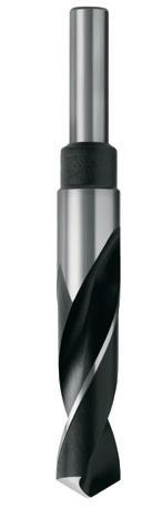
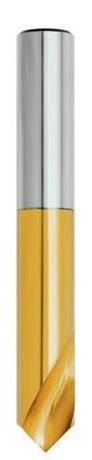
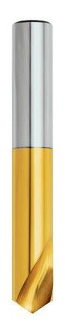
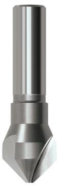
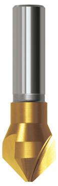
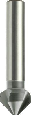
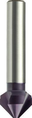
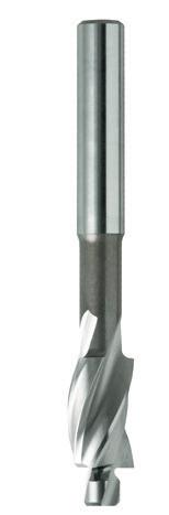
191 Ø 1 2 3 4 5 6 7 8 9 10 2.0 0.020 0.025 0.030 0.040 0.050 0.060 0.075 0.095 0.120 0.15
0.030 0.035 0.045 0.055 0.070 0.090 0.110 0.135 0.17 0.21
3.0
0.040 0.045 0.060 0.075 0.090 0.115 0.140 0.18 0.22 0.27 5.0 0.045 0.055 0.070 0.090 0.110 0.135 0.17 0.21 0.26 0.32 6.0 0.055 0.065 0.080 0.100 0.125 0.16 0.19 0.24 0.30 0.37
0.070 0.085 0.105 0.130 0.16 0.20 0.25 0.31 0.38 0.47 10.0 0.085 0.105 0.125 0.16 0.19 0.24 0.30 0.37 0.46 0.56 12.0 0.095 0.120 0.15 0.18 0.23 0.28 0.34 0.42 0.52 0.64 16.0 0.125 0.15 0.19 0.23 0.29 0.36 0.44 0.54 0.66 0.82 20.0 0.15 0.18 0.23 0.28 0.34 0.42 0.52 0.64 0.80 0.98 25.0 0.18 0.22 0.27 0.33 0.41 0.50 0.60 0.74 0.90 1.10 32.0 0.23 0.27 0.33 0.41 0.50 0.60 0.74 0.88 1.10 1.30 38.0 0.26 0.32 0.38 0.46 0.56 0.68 0.82 1.00 1.20 1.45 45.0 0.30 0.36 0.43 0.52 0.64 0.76 0.92 1.10 1.35 1.60 52.0 0.33 0.40 0.48 0.58 0.70 0.84 1.00 1.20 1.45 1.75 63.0 0.39 0.47 0.56 0.67 0.80 0.96 1.14 1.35 1.65 1.95 LONG SERIES TAPER SHANK REDUCED SHANK NC SPOTTING COUNTERBORES & COUNTERSINKS D113 D141 D115 D140 D188 D175 / D176 C105 C106 C107 C108 C100 HSS HSS Co HSS HSS HSS HSS Co HSS HSS Co HSS Co HSS Co Blu Colour Temp Blu Blu Blu TiN Brt TiN Brt TiAlN Brt N Tough Mat N N N N Machine Use N UNI N R30 R30 R30 R30 R30 90° / 120° 90° 90°≤ 7xØ ≤ 5xØ ≤ 5xØ ≤ 8xØ ≤ 5xØ - - -Vc Feed # Vc Feed # Vc Feed # Vc Feed # Vc Feed # Vc Feed # Vc Feed # Vc Feed # Vc Feed # Vc Feed # Vc Feed # VDI^ 3323 ISO 16 5 38 5 32 5 5 5 32 5 35 4 25 3 31 3 36 3 44 3 30 3 1 P 13 5 38 5 32 5 5 5 32 5 25 4 21 3 25 3 30 3 36 3 30 3 2 10 5 30 5 25 5 5 5 25 5 20 4 21 2 25 2 30 2 36 2 30 3 3 10 5 30 5 25 5 5 5 25 5 20 4 21 2 25 2 30 2 36 2 30 3 4 - - 18 4 15 4 4 4 15 4 15 3 - - 11 1 14 1 16 1 12 1 5 10 5 30 5 25 5 5 5 25 5 20 4 21 2 25 2 30 2 36 2 30 3 6 10 4 30 4 25 4 4 4 25 4 15 4 12 2 15 2 18 2 22 2 15 2 7 - - 18 4 15 4 4 4 15 4 15 3 - - 11 1 14 1 16 1 12 1 8 - - - - - - - - - - - - - - - - - - 10 1 10 1 9 10 5 18 4 15 4 4 4 15 4 15 3 10 1 11 1 14 1 16 1 12 1 10 - - - - - - - - - - - - - - - - - - 10 1 10 1 11 - - 10 4 - - - - - - 10 2 - - - - 10 1 12 1 14 1 12 - - - - - - - - - - 12 3 - - - - - - 10 1 10 1 13 7 4 12 4 8 4 4 4 8 4 10 3 - - 10 2 12 2 14 2 16 2 14.1 M - - 10 4 - - - 4 6 4 15 2 - - 8 1 10 1 12 1 12 1 14.2 - - 10 4 - - - - - - 10 2 - - 8 1 10 1 12 1 14 1 14.3 16 6 38 5 32 5 5 5 32 5 30 5 17 2 20 2 24 2 28 2 25 2 15 K 13 5 30 5 25 5 5 5 - - 20 4 17 2 20 2 24 2 28 2 16 2 16 13 6 25 5 20 5 5 5 20 5 20 4 15 2 15 2 20 2 25 2 20 2 17 13 6 25 5 20 5 5 5 - - 20 4 15 2 15 2 20 2 25 2 20 2 18 13 6 25 5 20 5 5 5 20 5 20 4 15 2 15 2 20 2 25 2 20 2 19 13 6 25 5 20 5 5 5 - - 20 4 15 2 15 2 - - 25 2 20 2 20 20 5 96 6 - - - - 80 6 50 5 34 4 41 4 48 4 58 4 80 4 21 N 20 5 96 6 - - - - 80 6 50 5 34 4 41 4 48 4 58 4 80 4 22 - - 72 5 - - - - 60 5 35 4 25 3 31 3 36 4 44 4 60 3 23 - - 72 5 - - - - 60 5 35 4 25 3 31 3 36 4 44 4 60 3 24 - - - - - - - - - - 30 4 - - - - 30 4 44 4 - - 25 - - 30 6 - - - - 25 6 40 4 55 2 66 2 78 2 94 2 80 2 26 - - 19 3 - - - - 16 3 30 4 34 2 40 2 48 2 58 2 - - 27 - - 38 6 - - - - 32 6 50 4 42 2 50 2 60 2 72 2 80 2 28 - - - - - - - - - - 30 4 - - - - 30 4 44 4 - - 29 - - - - - - - - - - - - - - - - - - - - - - 30 - - - - - - - - - - 9 2 - - - - 5 2 8 2 - - 31 S - - - - - - - - - - 8 2 - - - - 4 2 5 2 - - 32 - - - - - - - - - - 9 2 - - - - 5 2 8 2 - - 33 - - - - - - - - - - 8 2 - - - - - - 5 2 - - 34 - - - - - - - - - - - - - - - - - - 5 2 - - 35 - - - - - - - - - - - - - - - - 8 3 10 3 - - 36 - - - - - - - - - - 8 2 - - - - 7 3 9 3 - - 37.1 - - - - - - - - - - 8 2 - - - - 7 3 9 3 - - 37.2 - - - - - - - - - - - - - - - - - - 8 2 - - 37.3 - - - - - - - - - - 8 2 - - - - 7 3 9 3 - - 37.4 - - - - - - - - - - - - - - - - - - 8 2 - - 37.5 - - - - - - - - - - 10 3 - - - - - - - - - - 38.1 H - - - - - - - - - - - - - - - - - - - - - - 38.2 - - - - - - - - - - - - - - - - - - - - - - 39.1 - - - - - - - - - - - - - - - - - - - - - - 39.2 13 5 30 5 25 5 5 5 25 5 20 4 17 2 20 2 24 2 28 2 16 2 40 - - - - - - - - - - - - - - - - - - - - - - 41 Feed Table (f) (mm/rev) Feed # Ø = nominal tap size (mm) n = spindle speed (RPM) vc = cutting speed (m/min) f = feed
= feed rate
n = vc × 1000 vc x 318 Ø × π Ø vc = n x Ø × π n x Ø 1000 318 vf = f x n METRIC DRILLS (mm size) Contents Index
8.0
(mm/rev) vf
(mm/min)
Application Guide Speeds & Feeds - Taps
ISO VDI Material Group
P A Steel
M R Stainless Steel
K F Cast Iron
N N Non-Ferrous Metals, Aluminiums & Coppers
S S Titaniums & Super Alloys
H H Hard Materials (≥ 45 HRC) H ^ VDI 3323 material groups can also be determined by referring to the workpiece material cross reference listing. Refer to main index of this section. For expert tooling recommendations, go to: www.suttonhps.com
192
Sutton
N UNI
VA
GG
AI W
Ti Ni
FOR BLIND & THROUGH HOLES FOR THROUGH HOLES Catalogue Code M T384 / T385 / T386 / T901 T393 T394 T395 MF T401 / T402 / T403 / T902 T404 T406 T407 T408 UNC T414 / T415 / T416 / T903 T422 T423 T424 UNF T431 / T432 / T433 / T904 T439 T440 T441 BSW T451 / T452 / T453 / T905 T457 T458 T459 BSF, BA, BSB (Brass) T466 / T467 / T468 / T906 - - -G (BSPF) T479 / T480 / T481 / T909 T482 / T483 T484 -BSPT T475 T476 - -Material HSS HSSE Surface Finish Brt TiN Brt Blu TiN Sutton Designation N N Geometry Thread Depth ≤ 1xØ ≤ 3xØ ISO VDI^ 3323 Material Condition HB N/mm2 Vc (m/min) Vc (m/min) P 1 Steel - Non-alloy, cast & free cutting ~ 0.15 %C A 125 440 7 11 12 13 18 2 ~ 0.45 %C A 190 640 7 11 12 13 18 3 QT 250 840 6 9 10 11 15 4 ~ 0.75 %C A 270 910 7 10 11 12 17 5 QT 300 1010 5 8 - - 14 6 Steel - Low alloy & cast < 5% of alloying elements A 180 610 7 11 12 13 18 7 QT 275 930 5 7 8 9 12 8 QT 300 1010 4 5 - - 9 9 QT 350 1180 - - - -10 Steel - High alloy, cast & tool A 200 680 5 7 8 9 12 11 HT 325 1100 - - - -12 Steel - Corrosion resistant & cast Ferritic / Martensitic A 200 680 - - - 6 8 13 Martensitic QT 240 810 - - - -M 14.1 Stainless Steel Austenitic AH 180 610 - - - 7 9 14.2 Duplex 250 840 - - - 4 6 14.3 Precipitation Hardening 250 840 - - - 3 5 K 15 Cast Iron - Grey (GG) Ferritic / Pearlitic 180 610 7 11 12 13 18 16 Pearlitic 260 880 6 9 - - 15 17 Cast Iron - Nodular (GGG) Ferritic 160 570 7 11 12 13 18 18 Pearlitic 250 840 6 9 - - 15 19 Cast Iron - Malleable Ferritic 130 460 9 14 15 17 23 20 Pearlitic 230 780 7 11 12 13 18 N 21 Aluminum & Magnesium - wrought alloy Non Heat Treatable 60 210 7 11 12 - 18 22 Heat Treatable AH 100 360 9 14 15 - 23 23 Aluminum & Magnesium - cast alloy ≤12% Si Non Heat Treatable 75 270 9 14 15 - 23 24 Heat Treatable AH 90 320 9 14 15 - 23 25 Al & Mg - cast alloy >12% Si Non Heat Treatable 130 460 - - - -26 Copper & Cu alloys (Brass/Bronze) Free cutting, Pb > 1% 110 390 5 7 8 - 12 27 Brass (CuZn, CuSnZn) 90 320 11 16 18 - 27 28 Bronze (CuSn) 100 360 8 13 - -29 Non-metallic - Thermosetting & fiber-reinforced plastics - - - -30 Non-metallic - Hard rubber, wood etc. - - - -S 31 High temp. alloys Fe based A 200 680 - - - -32 AH 280 950 - - - -33 Ni / Co based A 250 840 - - - -34 AH 350 1180 - - - -35 C 320 1080 - - - -36 Titanium & Ti alloys CP Titanium 400 MPa - - - -37.1 Alpha alloys 860 MPa - - - -37.2 Alpha / Beta alloys A 960 MPa - - - -37.3 AH 1170 MPa - - - -37.4 Beta alloys A 830 MPa - - - -37.5 AH 1400 MPa - - - -H 38.1 Hardened steel HT 45 HRC - - - -38.2 HT 55 HRC - - - -39.1 HT 58 HRC - - - -39.2 HT 62 HRC - - - -40 Cast Iron Chilled C 400 1350 - - - -41 HT 55 HRC - - - -Condition: A (Annealed), AH (Age Hardened), C (Cast), HT (Hardened & Tempered), QT (Quenched & Tempered) Bold = Optimal | Regular = Effective Contents Index
HOLES
Notes on Tapping
1. The speeds listed above are a recommendation only, and are based on depth of thread listed, speeds can be adjusted on application. As a general rule; -If hole depth required is less than above mentioned = increase speed -If hole depth required is more than above mentioned = reduce speed
2. Taps must be driven by the square to eliminate slippage, eg, ER-GB collets (square drive).
3. When using spiral flute taps with length compensation tapping attachment, it is recommended to short pitch the feed 95%, to eliminate tap cutting oversize, eg. M6x1 @ 1000RPM, Feedrate= 950mm/min.
193
BLIND
THROUGH
T397 T396 T398 T399 T400 T409 - T411 -T425 T426 T427 T428 T429 T442 - T443 T444T460 T461 T462 T463 T464 - - - -T485 - - -- - - -HSSE HSSE Brt Blu TiN Brt TiN N N R40 ≤ 2.5xØ ≤ 1.5xØ Vc (m/min) Vc (m/min) VDI^ 3323 ISO 10 11 14 12 18 1 P 10 11 14 12 18 2 8 9 12 - 15 3 9 10 13 - 17 4 - - 11 - - 5 10 11 14 - 18 6 6 7 10 - - 7 - - 7 - - 8 - - - - - 9 6 7 10 - - 10 - - - - - 11 - 4 6 - - 12 - - - - - 13 - 5 7 - 9 14.1 M - 4 5 - 6 14.2 - 3 4 - - 14.3 10 11 14 - - 15 K - - 12 - - 16 10 11 14 - - 17 - - 12 - - 18 12 13 18 - - 19 10 11 14 - - 20 10 - 14 12 18 21 N 12 - 18 15 23 22 12 - 18 15 23 23 12 - 18 15 23 24 - - - - - 25 6 - 10 8 12 26 14 - 22 - - 27 - - - 14 21 28 - - - - - 29 - - - - - 30 - - - - - 31 S - - - - - 32 - - - - - 33 - - - - - 34 - - - - - 35 - - - - - 36 - - - - - 37.1 - - - - - 37.2 - - - - - 37.3 - - - - - 37.4 - - - - - 37.5 - - - - - 38.1 H - - - - - 38.2 - - - - - 39.1 - - - - - 39.2 - - - - - 40 - - - - - 41 Condition: A (Annealed), AH (Age Hardened), C (Cast), HT (Hardened & Tempered), QT (Quenched & Tempered) Bold = Optimal | Regular = Effective Ø = nominal tap size (mm) P = thread pitch (mm) n = spindle speed (RPM) vc = cutting speed (m/min) vf = feed rate (mm/min) vr = feed rate per rev (mm/rev) n = vc × 1000 vc x 318 Ø × π Ø vc = n x Ø × π n x Ø 1000 318 vf = n x P METRIC TAPS (mm size) Contents Index
FOR BLIND
FOR
&
HOLES
Application Guide Speeds & Feeds - HSS Endmills
N N Non-Ferrous Metals, Aluminiums & Coppers
S S Titaniums & Super Alloys
H H Hard Materials (≥ 45 HRC)
^ VDI 3323 material groups can also be determined by referring to the workpiece material cross reference listing. Refer to main index of this section. For expert tooling recommendations, go to: www.suttonhps.com

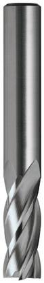
Notes on Milling
1. Above values are guidelines for the size and type of cut nominated. 2. For long series tools, reduce speed by 40% and feed by 20%.
194 ISO
Sutton
VDI Material Group
Steel N UNI
Stainless Steel VA
P A
M R
Iron GG
K F Cast
AI W
Ti Ni
H
Catalogue Code E100 E102 / E225 E184 E125 Material HSS Co.8 HSS Co.8 HSS Co.8 Surface Finish Brt Brt TiAlN Brt Sutton Designation N N N Geometry R30 R30 R30 Type of Cut: Slotting • • • Finishing • Universal • Roughing Profiling ap × Ø 0.5 0.5 0.5 1.5 1.5 ae × Ø 1.0 1.0 1.0 0.1 0.25 ISO VDI^ 3323 Material Condition HB N/mm2 Vc Feed # Vc Feed # Vc Feed # Vc Feed # Vc Feed # P 1 Steel - Non-alloy, cast & free cutting ~ 0.15 %C A 125 440 30 6 18 5 22 5 40 4 40 5 2 ~ 0.45 %C A 190 640 30 6 18 5 22 5 40 4 40 5 3 QT 250 840 30 6 18 5 22 5 40 4 40 5 4 ~ 0.75 %C A 270 910 30 6 18 5 22 5 40 4 40 5 5 QT 300 1010 20 5 12 4 15 4 25 3 25 4 6 Steel - Low alloy & cast < 5% of alloying elements A 180 610 30 6 18 5 22 5 40 4 40 5 7 QT 275 930 25 5 15 4 18 4 30 3 30 4 8 QT 300 1010 20 5 12 4 15 4 25 3 25 4 9 QT 350 1180 - - - - - - - - -10 Steel - High alloy, cast & tool A 200 680 20 5 12 4 15 4 25 3 25 4 11 HT 325 1100 - - - - - - - - -12 Steel - Corrosion resistant & cast Ferritic / Martensitic A 200 680 - - - - 11 4 10 2 10 3 13 Martensitic QT 240 810 15 4 9 3 11 3 22 3 22 4 M 14.1 Stainless Steel Austenitic AH 180 610 - - - - 11 4 - - -14.2 Duplex 250 840 - - - - 9 2 - - -14.3 Precipitation Hardening 250 840 - - - - - - - - -K 15 Cast Iron - Grey (GG) Ferritic / Pearlitic 180 610 30 5 18 4 21 4 35 3 35 4 16 Pearlitic 260 880 25 4 15 3 18 3 25 2 25 3 17 Cast Iron - Nodular (GGG) Ferritic 160 570 20 3 12 2 15 2 22 2 22 3 18 Pearlitic 250 840 20 3 12 2 15 2 22 2 22 3 19 Cast Iron - Malleable Ferritic 130 460 20 3 12 2 15 2 22 2 22 3 20 Pearlitic 230 780 20 3 12 2 15 2 22 2 22 3 N 21 Aluminum & Magnesium - wrought alloy Non Heat Treatable 60 210 70 6 42 5 51 5 70 5 70 6 22 Heat Treatable AH 100 360 70 6 42 5 51 5 70 5 70 6 23 Aluminum & Magnesium - cast alloy ≤12% Si Non Heat Treatable 75 270 50 5 30 4 33 4 55 4 55 5 24 Heat Treatable AH 90 320 50 5 30 4 33 4 55 4 55 5 25 Al & Mg - cast alloy >12% Si Non Heat Treatable 130 460 30 6 18 5 21 5 - - -26 Copper & Cu alloys (Brass/Bronze) Free cutting, Pb > 1% 110 390 25 5 15 4 18 4 40 4 40 5 27 Brass (CuZn, CuSnZn) 90 320 - - - - - - - - -28 Bronze (CuSn) 100 360 50 6 30 5 33 5 70 5 70 6 29 Non-metallic - Thermosetting & fiber-reinforced plastics - - - - - - - - -30 Non-metallic - Hard rubber, wood etc. - - - - - - - - -S 31 High temp. alloys Fe based A 200 680 - - - - - - - - -32 AH 280 950 - - - - - - - - -33 Ni / Co based A 250 840 - - - - - - - - -34 AH 350 1180 - - - - - - - - -35 C 320 1080 - - - - - - - - -36 Titanium & Ti alloys CP Titanium 400 MPa - - - - - - - - -37.1 Alpha alloys 860 MPa - - - - - - - - -37.2 Alpha / Beta alloys A 960 MPa - - - - - - - - -37.3 AH 1170 MPa - - - - - - - - -37.4 Beta alloys A 830 MPa - - - - - - - - -37.5 AH 1400 MPa - - - - - - - - -H 38.1 Hardened steel HT 45 HRC - - - - - - - - -38.2 HT 55 HRC - - - - - - - - -39.1 HT 58 HRC - - - - - - - - -39.2 HT 62 HRC - - - - - - - - -40 Cast Iron Chilled C 400 1350 - - - - - - 25 - 25 3 41 HT 55 HRC - - - - - - - - - -
Feed Table (fz) (mm/tooth) Ø Feed # 1 2 3 4 5 6 7 8 9 10 11 12 13 14 15 16 17 18 19 20 2 0.001 0.002 0.002 0.003 0.004 0.005 0.006 0.007 0.008 0.010 0.011 0.013 0.014 0.016 0.018 0.020 0.022 0.024 0.026 0.030 3 0.002 0.003 0.004 0.005 0.006 0.008 0.009 0.010 0.012 0.014 0.016 0.018 0.020 0.023 0.025 0.028 0.032 0.034 0.038 0.042 4 0.004 0.005 0.006 0.007 0.009 0.010 0.012 0.014 0.016 0.018 0.021 0.023 0.026 0.030 0.032 0.036 0.040 0.044 0.045 0.050 5 0.005 0.006 0.008 0.009 0.011 0.013 0.015 0.017 0.020 0.023 0.025 0.030 0.032 0.036 0.040 0.044 0.050 0.055 0.060 0.065 6 0.006 0.008 0.009 0.011 0.013 0.016 0.018 0.021 0.024 0.028 0.030 0.034 0.038 0.042 0.045 0.050 0.055 0.060 0.070 0.075 8 0.010 0.012 0.014 0.017 0.019 0.022 0.025 0.028 0.032 0.036 0.040 0.045 0.050 0.055 0.060 0.065 0.075 0.080 0.085 0.095 10 0.013 0.015 0.018 0.021 0.024 0.028 0.032 0.036 0.040 0.045 0.050 0.055 0.060 0.070 0.075 0.085 0.090 0.100 0.11 0.12 12 0.016 0.019 0.022 0.026 0.030 0.034 0.038 0.044 0.050 0.055 0.060 0.065 0.075 0.080 0.090 0.100 0.11 0.12 0.13 0.14 16 0.020 0.024 0.028 0.034 0.038 0.044 0.050 0.055 0.060 0.070 0.080 0.085 0.095 0.11 0.12 0.13 0.14 0.16 0.17 0.18 20 0.022 0.028 0.032 0.038 0.044 0.050 0.060 0.065 0.075 0.085 0.095 0.11 0.12 0.13 0.15 0.16 0.18 0.19 0.21 0.23 25 0.025 0.032 0.038 0.045 0.055 0.060 0.070 0.080 0.090 0.10 0.12 0.13 0.15 0.16 0.18 0.20 0.22 0.24 0.26 0.29
Contents Index
Condition: A (Annealed), AH (Age Hardened), C (Cast), HT (Hardened & Tempered), QT (Quenched & Tempered) Bold = Optimal | Regular = Effective
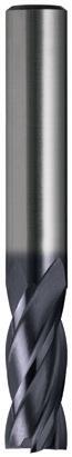
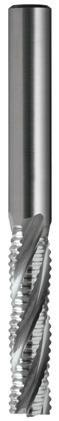
195 E192 E113 E146 HSS Co.8 HSS Co.8 HSS Co.8 TiAlN Brt Brt N N NR R30 R30 R30 NR (Long) • • • 1.5 0.05 1.5 0.1 0.02-0.05 0.25 Vc Feed # Vc Feed # Vc Feed # VDI^ 3323 ISO 50 4 40 5 30 5 1 P 50 4 40 5 30 5 2 50 4 40 5 30 5 3 50 4 40 5 30 5 4 30 3 30 4 30 5 5 50 4 40 5 30 5 6 40 4 35 4 30 5 7 30 3 30 4 30 5 8 25 3 - - - - 9 30 3 30 4 - - 10 25 3 - - - - 11 12 2 - - - - 12 25 3 - - - - 13 20 3 20 4 - - 14.1 M 15 1 15 2 - - 14.2 12 2 - - - - 14.3 40 3 40 4 40 8 15 K 30 2 30 3 - - 16 - - 25 2 10 8 17 - - 25 2 - - 18 - - 25 2 10 8 19 - - 25 2 - - 20 75 5 80 6 80 9 21 N 75 5 80 6 80 9 22 60 4 55 5 55 8 23 60 4 55 5 55 8 24 50 4 50 5 - - 25 40 4 25 5 25 6 26 - - - - - - 27 75 5 50 6 40 6 28 - - - - - - 29 - - - - - - 30 - - - - - - 31 S - - - - - - 32 - - - - - - 33 - - - - - - 34 - - - - - - 35 - - - - - - 36 - - - - - - 37.1 - - - - - - 37.2 - - - - - - 37.3 - - - - - - 37.4 - - - - - - 37.5 - - - - - - 38.1 H - - - - - - 38.2 - - - - - - 39.1 - - - - - - 39.2 - 3 - - - - 40 - - - - - - 41 Ø = nominal tool diameter (mm) n = Spindel speed (RPM) vc = Cutting speed (m/min) fz = Feed rate per tooth (mm/tooth) vf = Feed rate (mm/min) z = No. cutting edges Q = Metal removal rate (cm3/min) ap = Cutting depth (mm) ae = Cutting width (mm) n = vc × 1000 vc x 318 Ø × π Ø vc = n x Ø × π n x Ø 1000 318 fz = Vf vf = fz x z x n z x n Q = ap x ae × vf 1000 METRIC
size) Contents Index
ENDMILLS (mm
Application GuideTroubleshooting - Drills
Dull point
Sharpen
• Drill has front taper due to wearing Sharpen
Insufficient lip clearance on point
Grind correctly •
•
Lip clearance too great
Drill in incorrectly point ground
• • Flutes clogged with chips
• Spring or backlash in drill press, fixture or work
• • • • Feed too heavy
• Cutting speed too high
•
Dry cutting, no lubricant at cutting edges
• Drill web (core) diameter too big
• Fixture/Clamping not rigid
• Unequal angle or uneven length of cutting edges
• Spindle run-out/Loose spindle
• Bad fit between shank taper & socket. The drive & alignment is controlled by the taper fit
Regrind to correct clearance angle
Regrind correctly
Remove drill from hole and to clear flutes
Check each item for rigidity and alignment
Reduce Feed
Reduce speed
Apply cutting fluid
Thin web to original size
Secure job firmly
Regrind to same lip lengths and angles
Check machine
Remove dirt, nicks or burrs, or replace worn socket
196
Code Problem 1 Breaking of drill 2 Outer corner breaks down 3 Cutting edges chip 4 Drill splits up centre 5 Drill will not enter work 6 Hole rough 7 Hole oversize 8 Tang breaks
2 3 4 5 6 7 8 Possible Reason Solution • • •
1
• • •
•
•
Contents Index
5
Wrong tap, cutting geometry of the tap is not suitable for this operation
Tap hole diameter is undersize
Misalignment - tap hole position, or angle is not correct
Use correct tap for the material group. See Expert Tool Selector, at www.suttontools.com/expert-tool-selector
Tap hole diameter should be in accordance to DIN336 or respective standard. For cold forming taps, a special hole diameter is needed.
a) check workpiece clamping
b) check machine settings • The axial machine spindle movement is not free and easy
•
Cold welding on the thread flanks of the tap
• Poor guidance of the tap because of little thread depth
Speed is too high
• • • Chip clogging
a) use mechanical feed
b) use tap holder with length compensation
a) use a new tap
b) improve and check lubrication
c) remove cold welding area from tap
d) use tap with surface treatment or coatings
a) use mechanical feed
b) use tap that has better guiding characteristics
a) improve lubrication
b) lower speed
a) use tap with different flute form
b) use coated taps
c) use tap set •
•
•
• •
•
• • The lubrication wrong, additives or the coolant supply is not sufficient
Spiral fluted taps are over pressured in the initial cutting phase (retracting pulling force)
Spiral pointed taps (gun taps) are not receiving enough pressure in the initial cutting phase
Tolerance on the tap is not identical to the tolerance on the drawing or on the gauge
Wrong initial cutting pressure has been used or the machine spindle is not moving along its axis free and easy
• • Tap is over loaded, either from coarse pitch and/or tough material
• Cold welding, material build-up (pick-up)
• • Hardened walls in drilled hole
• Over loading of teeth in the chamfer area
Make sure that the coolant is correct and that the supply is sufficient
Spiral fluted taps should only be lightly pushed into the tap hole until it begins to cut. The tap holder should immediately begin to apply tension to the tap.
Spiral pointed taps and even left hand spiral flute taps must have a stronger pressure until they begin to cut.
The tap holder should immediately begin to apply pressure to the tap (pushing force)
Use a tap which has a correct tolerance
a) use mechanical feed
b) use tap holder with length compensation
Use set of taps
a) improve coolant supply, use taps with surface treatments or coatings
b) check if surface treatment is correct for this application
a) use drill best suited to material being drilled
b) use new drill or boring tool
c) resharpen drilling or boring tools
d) if possible, heat treatment and coatings should only be made after threading
a) use a longer chamfer (check if the tap hole is blind hole or through)
b) use increased number of teeth in the chamfer area by selecting tap with increased number of flutes
• Tap hole chamfer is missing or wrong Countersink tap hole chamfer with correct angle
• Tap crashed against the bottom of tap hole
Use tap holder with length compensation and over load clutch
197 Application Guide
- Taps Code Problem
Thread is oversize 2 Axial miscutting of thread 3 Thread is undersize 4 Thread has bellmouthed entry
Troubleshooting
1
Thread surface is rough and unclean
Low tool life
Partial
tap breakage on FORWARD
BACKWARD movement 1 2 3 4 5 6 7 Possible reason Solution • • • • • •
6
7
or complete
or
• • •
• • •
• •
•
Contents Index
Application Guide Troubleshooting - Endmills
198
Code Problem Possible Reason 1 Poor workpiece finish Cutting edge wear, cutter radial run-out 2 Splintering of workpiece edge Unsuitable cutting conditions, unsuitable shape of cutting edge 3 Non-parallel
uneven surface Low stiffness of
4 Extreme flank wear Unsuitable cutting conditions, unsuitable shape of cutting edge
Extreme crater wear
shelling due to thermal shock
Formation of built-up edges
Poor chip clearance, chip blockage 9 Lack of Rigidity Difficult cutting conditions, clamping of the workpiece 10 Endmill cutter breaks Unsuitable cutting conditions, flute length of the cutter 1 2 3 4 5 6 7 8 9 10 Solution • • • increase cutting speed • • • reduce cutting speed • • increase feed rate • • • • • • • • reduce feed rate • • • • • • • reduce cutting depth • • • change cutter diameter and cut width • • • • • check use of cooling lubricant, flush swarf away • • • • • • • • increase clearance angle (Radial relief) • • • increase wedge angle
angle) • increase number of teeth • • • • reduce number of teeth • select larger chip space
• • • • • change shape of minor cutting edge • • cutter - change radial run-out • • • • • change cutter stiffness, flute length (l/D ratio) • • • • select machine with higher power and stiffness Contents Index
or
the cutter or of the workpiece (loose)
5
6 Breaks and
7
8
(Rake
(Cutter)
• • Dirt or burrs in spindle or socket in which reamer is held clean spindle
• • Misalignment of two or more parts of the set-up. This condition can cause a bell-mouthed hole align holes or use bridge style reamer
•
• • Too fast or too slow speeds adjust
• • • • Too much or too little feed adjust
• Wrong type of coolant refer to lubricant supplier’s literature
• No lubricant between guide bushing and reamer apply
• • Lack of lubricant increase
• Bottoming in blind holes reduce depth travel of reamer
• Lack of sufficient stock to ream drill smaller hole
•
• • Too much stock to ream drill larger hole
• • Entering work too fast slow down the approach feed, until all cutting edges are located in the hole
• • Badly drilled holes – too rough, tapered or bell-mouthed. Bellmouthed holes may cause the reamer to wedge rather than cut replace drill • • Oversize or undersize bushings use suitable bush
• • Lack of rigidity in machine or work holder improve rigidity
• • • Improperly designed reamer for the job use a different reamer
199
- Reamers Code Problem 1 Breakage 2 Excessive wear 3 Chattering 4 Poor surface finish 1 2 3 4 Possible reason Solution
Application Guide Troubleshooting
•
•
•
Contents Index
Blue - Grey
• Low alloy steels and high tensile steels
• Hardened steels up to 54 HRC
• Ideal for carbide tools Aldura TiAlN + AlCrN
• High speed machining
• Suitable for minimum quantity lubrication (MQL) and dry machining
• Machining of hardened steels (>60HRC)
• Ideal for carbide tools AlNova Alcrona based
• Even high thermal stresses hardly effect the superior hardness of the coating
• Its high hot hardness results in excellent abrasion resistance even at high cutting speeds
• For ferrous metals
• Prevents chip build-up on the cutting edges, especially in low carbon steels
• Oxide layer protects surface
• Good carrier of lubricants
• For general purpose applications
• Cutting and forming of copper, nickel, & monel metal
• Enhanced thermal stability and oxidation resistance
• Excellent corrosion resistance
• Abrasive materials - cast iron and heat treated steel
• Difficult to machine materials, such as stainless steel
• Low internal stress of coating results in excellent adhesion under high loads Futura Nano (TiAlN)
• Higher speeds and feeds
• Reduces or eliminates use of coolants
• Excellent friction and lubricating properties of the coating provide optimal chip flow
• Tapping and drilling of hard to machine materials
• Suitable for minimum quantity lubrication (MQL) and dry machining Helica Alcrona based Multi
• Longer tool life
• Higher cutting speeds and feeds
• Superb chip evacuation
• Greater number of regrinds
• Improved drill hole quality
• Excellent performance in abrasive material
• Increases surface hardness
• Better lubricant carrying properties
• Abrasive materials - cast iron and Aluminium alloys TiN Titanium Nitride Mono Layer 2300 HV 0.4 up to 1112°F Gold - Yellow
• General purpose use
• Wide range of materials
• 3 to 8 times longer tool life than uncoated tools
• High performance applications
• Difficult to machine materials
• Higher tool speeds and feeds than uncoated tools TiCN Titanium Carbonitride Gradient Coating
TiSiN TiSi based Multi Layer 3600 HV 0.3 <1200°C Copper
• Abrasive materials - cast iron and Aluminium alloys
• Adhesive materials - copper and copper based alloys
• Suitable for high speed (wet / dry) and hard machining for difficult materials above 52 HRC.
• Suitable for high speed machining with hardened steels above 60 HRC to maximum of 63 HRC
• Vc & Vf = +50% Latest advances in thin film coatings to optimise your machining application
200 Technical Information Coatings & Surface Finish Trade Name Coating Coating Structure Microhardness Coeff. of Friction vs Steel Thermal Stability Colour Application
Benefits
&
Layer
0.35 up to 2012°F
Alcrona (AlCrN) Aluminium Chromium Nitride Mono
3200 HV
Multi Layer 3300 HV <0.4 >1100°C
Blue - Grey
Layer 3200 HV 0.35
Multi
>1100°C Light Grey
Blu
- - 0.8 - 1.0 - Blue -
Steam Oxide
Black
Brt - - - 0.8 - 1.0 - -
Coating 1750 HV 0.5 up to 1292°F
CrN Chromium Nitride Gradient
Silver - Grey
Titanium
3300
0.3
0.35
1652°F
Aluminium Nitride Nano Layer
HV
-
up to
Violet - Grey
TiAlN + WC/C Nano Layer 3000 HV 0.15-0.20 up to 1472°F
Hardlube
Dark Grey
3000 HV 0.25 up to 1100°C
Layer
Copper
- -
- -
Ni Plasma Nitride
0.8 - 1.0
3000 HV 0.4 up to 752°F Blue - Grey
Contents Index
Abbreviations Type
HSS
HSS Co
HSSE Co 8%
Conventional high speed steel
5% cobalt grade of high speed steel
8% cobalt grade of high speed steel
HSSE Premium grade of high speed steel
PM-HSSE V3
PM-HSS Co
SPM
VHM
VHM
VHM-ULTRA
Powdered metallurgy - vanadium grade of high speed steel
Powdered metallurgy - 8% Cobalt grade of high speed steel
Powdered metallurgy - 11% Cobalt grade of high speed steel
Sub-micron grade of solid Carbide (ISO K15-K30)
Sub-micron grade of solid Carbide (ISO K40)
Sub-micron grade of solid Carbide (ISO K40-K50)
Application
Standard tool material for most common applications
High-heat resistance, especially suited for roughing or when coolant insufficient
Increased heat resistance and hardness, suitable for difficult-to-machine materials
Wide range of machine taps
Materials with hardness up to 40 HRC
Difficult-to-machine materials eg. stainless steels
Materials with hardness up to 45 HRC
Special applications, requiring very high edge hardness.
Cutting tools with the appropriate geometry can be applied to workpiece materials with hardness up to 55 HRC
Tapping hardened steel
Sutton standard grade for endmills & drills
High performance grade for endmills
Description
Used for the manufacturing of cutting tools such as twist drills, endmills and taps.
Cobalt alloyed, tungsten-molybdenum high speed steel possessing high hardness, excellent cutting properties, high-red hardness and good toughness.
Available for applications that require a strong resistance to softening at elevated cutting temperatures. The ability of the steel to maintain its “red-hot hardness” is provided by the addition of cobalt. The high hot hardness is required for machining difficult materials such as nickel-base, titanium and highly alloyed steel.
Vanadium grade gives high wear resistance and toughness for most tapping applications.
PM-HSS V3 for higher performance tools, incorporates very fine and uniform grain structure allowing a high hardness to be achieved, whilst maintaining good toughness.
The addition of cobalt provides this material with the ability to maintain its strength and hardness level when exposed to extremely high cutting temperatures. This makes PM-HSS Co suitable for heavy duty tapping, in materials such as high alloyed steels to non-ferrous metals like Ni-base alloys & Ti-alloys.
An excellent bridge material between high speed steel and carbide. SPM offers very high red hardness, wear resistance and the highest compressive strength of any high speed steel.
Ultra fine grain type (0.8µm) with maximum toughness & high hardness, therefore especially recommended for rotating tools to machine hardened parts.
Ultra fine grain type (0.6µm) offers the ideal combination of hardness & toughness for high performance drilling & general milling applications
Ultra fine grain type (0.5µm) offers the best wear resistance for high performance milling applications.
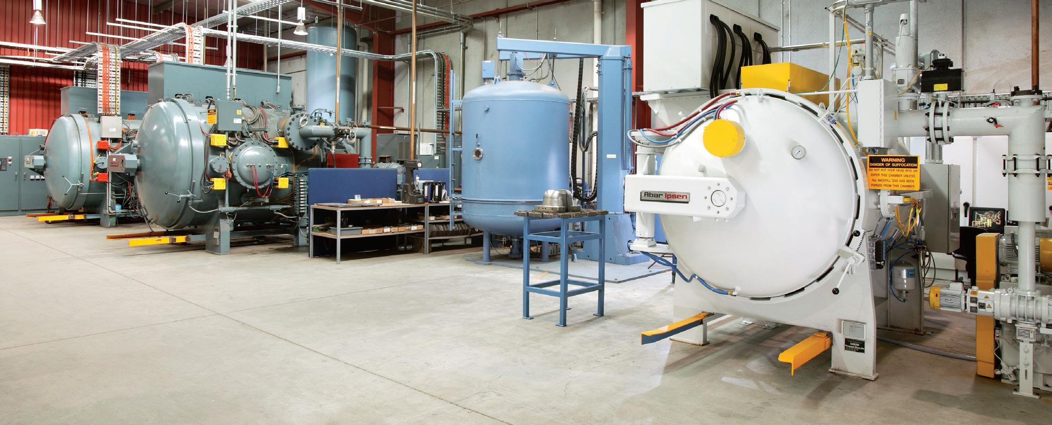
201
consistent high
Technical Information Materials - Tool Contents Index
Computer controlled vacuum heat treatment ensures
quality
Metric Imperial Inch Gauge
0.010 0.0004
0.100 0.0039
0.150 0.0059 97
0.160 0.0063 96
0.170 0.0067 95 0.180 0.0071 94
0.190 0.0075 93
0.200 0.0079 92
0.210 0.0083 91
0.220 0.0087 90 0.230 0.0091 89
0.240 0.0094 88 0.254 0.0100 87
0.270 0.0106 86 0.280 0.0110 85 0.290 0.0114 84 0.300 0.0118 0.305 0.0120 83
0.317 0.0125 82 0.330 0.0130 81 0.343 0.0135 80
0.368 0.0145 79
0.397 1/64 0.0156
0.400 0.0157 0.406 0.0160 78
0.457 0.0180 77
0.500 0.0197
0.508 0.0200 76
0.533 0.0210 75 0.572 0.0225 74
0.600 0.0236
0.610 0.0240 73
0.635 0.0250 72
0.660 0.0260 71 0.700 0.0276
0.711 0.0280 70
0.742 0.0292 69
0.787 0.0310 68 0.794 1/32 0.0313 0.800 0.0315
0.813 0.0320 67
0.838 0.0330 66 0.889 0.0350 65
0.0354
0.0360 64
0.0370 63
7/32 0.2188 5.600 0.2205 5.613 0.2210 2 5.700 0.2244 5.791 0.2280 1 5.800 0.2283 5.900 0.2323 5.944 0.2340 A 5.953 15/64 0.2344 6.000 0.2362
202
0.900
0.914
0.940
0.965
0.991
1.016
59 1.067 0.0420 58 Metric Imperial Inch Gauge 1.092 0.0430 57 1.181 0.0465 56 1.191 3/64 0.0469 1.321 0.0520 55 1.397 0.0550 54 1.500 0.0591 1.511 0.0595 53 1.588 1/16 0.0625 1.613 0.0635 52 1.702 0.0670 51 1.778 0.0700 50 1.854 0.0730 49 1.900 0.0748 1.930 0.0760 48 1.984 5/64 0.0781 1.994 0.0785 47 2.000 0.0787 2.057 0.0810 46 2.083 0.0820 45 2.184 0.0860 44 2.261 0.0890 43 2.375 0.0935 42 2.381 3/32 0.0938 2.438 0.0960 41 2.489 0.0980 40 2.500 0.0984 2.527 0.0995 39 2.578 0.1015 38 2.642 0.1040 37 2.705 0.1065 36 2.778 7/64 0.1094 2.794 0.1100 35 2.819 0.1110 34 2.870 0.1130 33 2.946 0.1160 32 3.000 0.1181 3.048 0.1200 31 3.100 0.1220 3.175 1/8 0.1250 3.200 0.1260 3.264 0.1285 30 3.300 0.1299 3.400 0.1339 3.454 0.1360 29 3.500 0.1378 3.569 0.1405 28 3.572 9/64 0.1406 3.600 0.1417 3.658 0.1440 27 3.700 0.1457 3.734 0.1470 26 3.797 0.1495 25 Metric Imperial Inch Gauge 3.800 0.1496 3.861 0.1520 24 3.900 0.1535 3.912 0.1540 23 3.969 5/32 0.1563 3.988 0.1570 22 4.000 0.1575 4.039 0.1590 21 4.089 0.1610 20 4.100 0.1614 4.200 0.1654 4.216 0.1660 19 4.300 0.1693 4.305 0.1695 18 4.366 11/64 0.1719 4.394 0.1730 17 4.400 0.1732 4.496 0.1770 16 4.500 0.1772 4.572 0.1800 15 4.600 0.1811 4.623 0.1820 14 4.700 0.1850 13 4.762 3/16 0.1875 4.800 0.1890 12 4.851 0.1910 11 4.900 0.1929 4.915 0.1935 10 4.978 0.1960 9 5.000 0.1969 5.055 0.1990 8 5.100 0.2008 5.105 0.2010 7 5.159 13/64
5.556
Technical Information Conversion Tables Contents Index
0.0380 62
0.0390 61 1.000 0.0394
0.0400 60 1.041 0.0410
0.2031 5.182 0.2040 6 5.200 0.2047 5.220 0.2055 5 5.300 0.2087 5.309 0.2090 4 5.400 0.2126 5.410 0.2130 3 5.500 0.2165
Metric Imperial Inch Gauge
6.045 0.2380 B
6.100 0.2402
6.147 0.2420 C
6.200 0.2441
6.248 0.2460 D
6.300 0.2480
6.350 1/4 0.2500 E
6.400 0.2520
6.500 0.2559
6.528 0.2570 F
6.600 0.2598
6.629 0.2610 G
6.700 0.2638
6.747 17/64 0.2656
6.756 0.2660 H
6.800 0.2677
6.900 0.2717
6.909 0.2720 I
7.000 0.2756
7.036 0.2770 J
7.100 0.2795
7.137 0.2810 K
7.144 9/32 0.2813
7.200 0.2835
7.300 0.2874
7.366 0.2900 L
7.400 0.2913
7.493 0.2950 M
7.500 0.2953
7.541 19/64 0.2969
7.600 0.2992
7.671 0.3020 N
7.700 0.3031
7.800 0.3071
7.900 0.3110
7.938 5/16 0.3125
8.000 0.3150
8.026 0.3160 O
8.100 0.3189
8.200 0.3228
8.204 0.3230 P
8.300 0.3268
8.334 21/64 0.3281
8.400 0.3307
8.433 0.3320 Q
8.500 0.3346
8.600 0.3386
8.611 0.3390 R
8.700 0.3425
8.731 11/32 0.3438
8.800 0.3465
8.839 0.3480 S
Metric
Imperial Inch Gauge 8.900 0.3504 9.000 0.3543 9.093 0.3580 T 9.100 0.3583 9.128 23/64 0.3594 9.200 0.3622 9.300 0.3661 9.347 0.3680 U 9.400 0.3701 9.500 0.3740 9.525 3/8 0.3750 9.576 0.3770 V 9.600 0.3780 9.700 0.3819 9.800 0.3858
0.3860 W
X
0.4040 Y
7/8 0.8750
0.8858 22.622 57/64 0.8906 23.000 0.9055 23.019 29/32 0.9063 23.416 59/64 0.9219 23.500 0.9252
15/16 0.9375
0.9449
61/64 0.9531 24.500 0.9646 24.606 31/32 0.9688
0.9843 25.003 63/64 0.9844 25.400 1 1.0000
203
9.900
9.922
10.000
10.084
10.200
10.262
10.319 13/32 0.4063 10.490 0.4130
10.500 0.4134 10.716 27/64 0.4219 10.800 0.4252 11.000
11.112
11.200
11.500 0.4528 11.509 29/64 0.4531 11.800 0.4646 11.906 15/32 0.4688 12.000 0.4724 12.200 0.4803 12.303 31/64 0.4844 12.500 0.4921 12.700 1/2 0.5000 12.800 0.5039 13.000 0.5118 13.097 33/64 0.5156 13.494 17/32 0.5313 13.500 0.5315 13.891 35/64 0.5469 14.000 0.5512 14.288 9/16 0.5625 14.500 0.5709 14.684 37/64 0.5781 15.000 0.5906 15.081 19/32 0.5938 15.478 39/64 0.6094 Metric Imperial Inch Gauge 15.500 0.6102 15.875 5/8 0.6250 16.000 0.6299 16.272 41/64 0.6406 16.500 0.6496 16.669 21/32 0.6563 17.000 0.6693 17.066 43/64 0.6719 17.462 11/16 0.6875 17.500 0.6890 17.859 45/64 0.7031 18.000 0.7087 18.256 23/32 0.7188 18.500 0.7283 18.653 47/64 0.7344 19.000 0.7480 19.050 3/4 0.7500 19.447 49/64 0.7656 19.500 0.7677 19.844 25/32 0.7813 20.000 0.7874 20.241 51/64 0.7969 20.500 0.8071 20.638 13/16 0.8125 21.000 0.8268 21.034 53/64 0.8281 21.431
21.500
21.828
22.000
22.225
Technical Information Conversion Tables Contents Index
9.804
0.3898
25/64 0.3906
0.3937
0.3970
0.4016
Z
0.4331
7/16 0.4375
0.4409
27/32 0.8438
0.8465
55/64 0.8594
0.8661
22.500
23.812
24.000
24.209
25.000
Tensile Strength vs Hardness (≈)
Conversion of values depends on the actual alloy content; this chart therefore indicates a general conversion only.
Manufacturing Tolerances
Conversion: 1 micron equals .00004 inches
204
Tensile Strength Hardness N/mm2 Kg/mm2 Tons/Inch2 Brinell [HB] Rockwell [HRC (HRB)] 400 40.8 26.0 119 69 HRB 450 45.9 29.0 133 75 HRB 500 50.1 32.4 149 81 HRB 550 56.0 35.6 163 85.5 HRB 600 61.0 38.9 178 89 HRB 650 66.2 42.1 193 92 HRB 700 71.4 45.3 208 95 HRB 750 76.5 48.5 221 97 HRB 800 81.6 51.8 238 22 HRC 850 86.7 55.1 252 25 HRC 900 91.8 58.3 266 27 HRC 1000 102.0 64.7 296 31 HRC 1100 112.2 71.2 325 35 HRC 1200 122.4 77.7 354 38 HRC 1300 132.6 84.1 383 41 HRC 1400 142.8 90.5 408 44 HRC 1500 152.9 97.0 444 47 HRC 1600 163.1 103.5 461 49 HRC 1700 173.3 109.9 477 50 HRC 1800 183.5 116.4 514 52 HRC 1900 193.7 122.9 549 54 HRC 2000 203.9 129.3 584 56 HRC 2100 214.1 135.8 607 57 HRC 2200 224.3 142.2 622 58 HRC 2300 233.1 148.7 653 60 HRC
Nominal Diameter in mm above up to and including Tolerance Grade in Microns 1 Micron = 0.001mm e8 h5 h6 h7 h8 h9 h10 js12 js14 k8 k9 k10 m7 0 3 -14 0 0 0 0 0 0 +50 +125 +14 +25 +40 +12 -18 -4 -6 -10 -14 -25 -40 -50 -125 0 0 0 +2 3 6 -20 0 0 0 0 0 0 +60 +150 +18 +30 +48 +16 -38 -5 -8 -12 -18 -30 -48 -60 -150 0 0 0 +4 6 10 -25 0 0 0 0 0 0 +75 +180 +22 +36 +58 +21 -47 -6 -9 -15 -22 -36 -58 -75 -180 0 0 0 +6 10 18 -32 0 0 0 0 0 0 +90 +215 +27 +43 +70 +25 -59 -8 -11 -18 -27 -43 -70 -90 -215 0 0 0 +7 18 30 -40 0 0 0 0 0 0 +105 +260 +33 +52 +84 +29 -73 -9 -13 -21 -33 -52 -84 -105 -260 0 0 0 +8 30 50 -50 0 0 0 0 0 0 +125 +310 +39 +62 +100 +34 -89 -11 -16 -25 -39 -62 -100 -125 -310 0 0 0 +9 50 80 -60 0 0 0 0 0 0 +150 +370 +46 +74 +120 +41 -106 -13 -19 -30 -46 -74 -120 -150 -370 0 0 0 +11 80 120 -72 0 0 0 0 0 0 +175 +435 +54 +87 +140 +48 -126 -15 -22 -35 -54 -87 -140 -175 -435 0 0 0 +13
Technical Information Useful Tables Contents Index
High Speed Steel Straight Shanks
Form A (plain)
205
Form B (with drive flat) d1 h6 b1 +0.05 -0 c1 0 -1 h1 h13 l1 +2 -0 l2 +1 -0 6 4.2 18 4.8 368 5.5 18 6.6 3610 7 20 8.4 4012 8 22.5 10.4 4516 10 24 14.2 4820 11 25 18.2 5025 12 32 23 56 17 32 14 36 30 60 19 40 14 40 38 70 19 50 18 45 47.8 80 23 63 18 50 60.8 90 23 Form D
d1 l1 +2 -0 l3 +1 -0 d2 6 36 10 5.9 10 40 10 9.9 12 45 10 11.9 16 48 10 15.9 20 50 15 19.9 25 56 15 24.9 32 60 15 31.9
d1 h6 l1 +2 -0 d1 h6 l1 +2 -0 3 28 16 48 4 28 20 50 5 28 25 56 6 36 32 60 8 36 40 70 10 40 50 80 12 45 63 90 Technical Information Shank Designs - HSS Tools centre hole chamfer centre hole chamfer centre hole chamfer centring hole thread profile DIN ISO 228 Whitworth Form thread undercut or thread run out released 1.27 / 20TPI 1.27 / 20TPI Contents Index
DIN 1835
(screwed shank)
Carbide Straight Shanks
Form HA (plain) DIN6535
6
8
206 Technical Information Shank Designs - Carbide Tools
d1 h6 b1 +0.05 -0 c1 0 -1 h1 h11 l1 +2 -0 l2 +1 -0
Form HB (with drive flat)
4.2 18 5.1 36 -
5.5 18 6.9 3610 7 20 8.5 4012 8 22.5 10.4 4514 8 22.5 12.7 4516 10 24 14.2 4818 10 24 16.2 4820 11 25 18.2 5025 12 32 23 56 17 32 14 36 30 60 19 Form HE
flat) d1 h6 b2 b3 h2 h11 h3 l1 +2 0 l4 0 -1 l5
4.3 - 5.1 - 36 25 18
5.5 - 6.9 - 36 25 18 10 7.1 - 8.5 - 40 28 20 12 8.2 - 10.4 - 45 33 22.5 14 8.1 - 12.7 - 45 33 22.5 16 10.1 - 14.2 - 48 36 24 18 10.8 - 16.2 - 48 36 24 20 11.4 - 18.2 - 50 38 25 25 13.6 9.3 23 24.1 56 44 32 32 15.5 9.3 30 31.2 60 48 35
d1 h6 l1 +2 -0 d1 h6 l1 +2 -0 2 28 12 45 3 28 14 45 4 28 16 48 5 28 18 48 6 36 20 50 8 36 25 56 10 40 32 60 1.27 / 20TPI 1.27 / 20TPI l1 l4 l5 d1 d1 b2 b3 h 2 Other
Chamfer 47º 43º 6 2º ( ) ( ) (h 3 ) 6mm to 20mm = One Drive Flat 25mm & 32mm = Two Drive Flats 6mm to 20mm = One Drive Flat 25mm & 32mm = Two Drive Flats chamfer chamfer chamfer chamfer Contents Index
(with whistle notch
6
8
dimensions and date as for figure 4
Drill Definitions
*Drills
Drill Point Types (DIN1412)
Type A thinned chisel edge
Drill Tolerances DIN / ISO 286, Part 2
207
Drill Diameter at Point (mm) Diameter Tolerance h8 (mm) Back Taper (mm) Over Inclusive Plus (+) Minus (-) (Tapering of Diameter)† 0.20 3.00 0.000 0.014 0.000 to 0.008 3.00 6.00 0.000 0.018 0.002 to 0.008 6.00 10.00 0.000 0.022 0.002 to 0.009 10.00 18.00 0.000 0.027 0.003 to 0.011 18.00 30.00 0.000 0.033 0.004 to 0.015 30.00 50.00 0.000 0.039 0.004 to 0.015
end; tolerance per 10mm of flute length.
† The Drill diameter usually reduces towards the shank
overall length and flute length are measured to the corner of the outer lip. THINNED WEB THINNED
manufactured to ANSI B94-11. The
Terminology tang tang drive shank diameter fluted land point angle drill diameter shank length overall length body flute length helix angle neck lip relief angle clearance diameter chisel edge width of land margin chisel edge angle lip web
Technical Information Drill
Type D point ground for cast iron
Type B thinned chisel edge with corrected cutting lips
split
lip Contents Index
Type E brad point Type C
point
Web Thinning
On most drills the web increases in thickness towards the shank with the result that, as the drill is shortened by repeated sharpening, the chisel edge will become wider. As the chisel edge does not cut but forces the metal out of the way, too wide a chisel edge will result in more pressure required for penetration, leading to greater heat generation and a resultant loss of life.
Cutting Fluids
The use of cutting fluids is an advantage in most drilling operations and an essential in some. The two main functions of the cutting fluid are lubrication and cooling. The purpose of lubrication is to reduce friction by lubricating the surfaces tool and work, to facilitate easier sliding of the chips up the flute and to prevent the chips welding to the cutting edges. In production work, particularly when drilling deep holes, the cooling action of the fluid is often more important than the lubrication. Overheating will shorten the life of the drill. Intermittent feed on deep holes, where possible, not only clears the chips but permits more effective cooling.
Speeds
The speed of a drill is the rate at which the periphery of the drill moves in relation to the work being drilled. As a rule, with a drill working within its speed range for a specific material, more holes between sharpening will be achieved if the speed is reduced and less holes if the speed is increased. Thus, for each production run, a speed must be established which will result in the highest rate of production without excessive breakdown time or drill usage. The factors governing speed are: component material, hardness of material, depth of hole, quality required, condition of drilling machine, efficiency of cutting fluid.
Feeds
The feed of the drill is governed by the drill size and the component material. As with speeds, an increase in feed will lessen the number of holes produced sharpening but it is essential that a constant feed be maintained. If a drill is allowed to dwell, breakdown of the cutting edges will result.
Small Drill Feeds and Speeds
Breakdown of small drills can most often be attributed to two faults: speed too high and feed too low. A feed which will produce CHIPS not POWDER, coupled with a speed compatible with the strength of the drill is essential for small hole drilling. Feeds must be based on thickness of chip, not mm/min, and speeds adjusted accordingly. EXAMPLE: A 1mm drill is to operate at a feed of 0.013mm /rev, drilling steel. While the material may permit a speed of 30m/min or 9,500 RPM it is obvious that the drill could not withstand a load of 0.013mm feed at this speed; a penetration rate of 124mm/min. The correct procedure is to retain the feed but reduce the speed to obtain a penetration within the capacity of the strength of the drill.
Deep Hole Drilling
When drilling deep holes, speeds and feeds should be reduced as follows:
3 times drill diameter
4 times drill diameter
5 times drill diameter 30 20
6 to 8 times drill diameter 35 to 40 20
208
Depth of hole Reduction percent % Speed Feed
10
10
30 10
A HOLD ORIGINAL THICKNESS Technical Information Hints on Use & Maintenance hold original thickness Contents Index
Tap Definitions
Thread Relief Types
Cutting Faces
of shank
overall length
209 Section A-A
Technical Information Tap Terminology
shank diameter root lead angle minor diameter pitch diameter major diameter
crest front flank rear flank
width of land cutting face flute web diameter shear angle Gun nose (spiral point)
length
threaded length pitch chamfer lead length length of square
square size
included angle of thread semi-angle of thread
Concentric threads (no radial relief)
a
radial relief concentric land radial relief Negative rake Radial rake Positive rake Hook heel negative rake angle positive rake angle land tangential hook chordal hook angle Contents Index
Eccentric threads (relieved to cutting edge) Con-eccentric threads (relieved to
land)
Construction dimensions / designs
Short Machine & Hand Taps ISO 529 JIS (J TYPE)
Reinforced Shank Taps DIN371
Reduced Shank Taps DIN374 / DIN376 / DIN5156
Machine Nut Taps ANSI B949 Standard
Pipe Taps
Tap Styles
Rc(BSPT), G (BSPF), Rp (BSPPL) - ISO2284 Standard NPT, NPTF, NPSF - ANSI B949 Standard
Chamfer Type / Length
Table below is in accordance with ISO8830 / DIN2197 Terminology
210 Technical Information Taps
Form Number of threads on lead Chamfer angle (≈) Type of flute Main area of application Illustration TAPER A 6 to 8 5° Hand or straight flutes Short through holes INTERMEDIATE D 3.5 to 5 8° Hand or straight Generally for through holes
E* 1.5 to 2 23° Hand or straight flutes Blind holes with very short thread run out INTERMEDIATE B 3.5 to 5 10° Straight, with spiral point Through holes in medium & long chipping materials BOTTOMING C 2 to 3 15° Spiral fluted Generally for blind holes Use of this type is not recommended Style Standard Illustration
BOTTOMING
Style 1 3 Lobe 4 Lobe Style 3 Style 4 Style 5 Style 6 l 2 l 1 d 2 sq l 2 l 1 sq d 2 l 2 l 1 sq d 2 l 2 l 1 sq d 2 l 2 l 1 sq d 2 l 2 l 1 sq d 2 l 3 Style 2 l 3 Style 1 3 Lobe 4 Lobe Style 3 Style 4 Style 5 Style 6 l 2 l 1 d 2 sq l 2 l 1 sq d 2 l 2 l 1 sq d 2 l 2 l 1 sq d 2 l 2 l 1 sq d 2 l 2 l 1 sq d 2 l 3 Style 2 l 3 Style 1 3 Lobe 4 Lobe Style 3 Style 4 Style 5 Style 6 l 2 l 1 d 2 sq l 2 l 1 sq d 2 l 2 l 1 sq d 2 l 2 l 1 sq d 2 l 2 l 1 sq d 2 l 2 l 1 sq d 2 l 3 Style 2 l 3 Style 1 Style 3 Style 4 Style 5 Style 6 l 2 l 1 d 2 sq l 2 l 1 sq d 2 l 2 l 1 sq d 2 l 2 l 1 sq d 2 l 2 l 1 sq d 2 l 2 l 1 sq d 2 l 3 Style 2 l 3 Style 1 3 Lobe 4 Lobe Style 3 Style 4 Style 5 Style 6 l 2 l 1 d 2 sq l 2 l 1 sq d 2 l 2 l 1 sq d 2 l 2 l 1 sq d 2 l 2 l 1 sq d 2 l 2 l 1 sq d 2 l 3 Style 2 l 3 Style 1 Style 3 Style 4 Style 5 Style 6 l 2 l 1 d 2 sq l 2 l 1 sq d 2 l 2 l 1 sq d 2 l 2 l 1 sq d 2 l 2 l 1 sq d 2 l 2 l 1 sq d 2 l 3 Style 2 l 3 Contents Index
Tap Types - Helix direction/ Helical pitch / Fluteless
The helix angle depends primarily upon the hole form, eg. Through hole , blind hole, deep blind hole, etc., but the material, eg short chips, long chips, also has a strong influence on the direction of the helix. The following basic forms have derived during the development of taps:
Description
1 Straight Flutes (Hand) - Suitable for through or blind holes. The flutes only have room for a small amount of chips. The chips are not transported axially. Therefore, it is not advisable to cut deep through or blind holes (except in short chipping materials), with this type.
2 Straight Flutes with (Gun) – Suitable for through holes, the gun point curls the chip forward ahead of the tap & out of the hole. Therefore, chip clogging is avoided and coolant can flow without problems.
3 Spiral Flutes (LH Spiral, right hand cutting) – Suitable for interrupted through holes, where cross-holes exist. The direction of the flutes, curls & transports the chips forward of the tap, similar to Gun taps (also, opposite to RH spiral flutes). However, in applications where another hole intersects with the tapped hole, the helical flutes maintain the pitching of the thread.
4 15° Spiral Flutes (RH Spiral) – Suitable for blind holes, best suited to tough short chipping materials, up to 1.5 x D in depth. This particular tap design has no advantages for soft, and long chipping materials, especially over 1.5 x d1 in depth. Due to the slow helix angle not transporting the chips well, clogging is possible.
5 40° to 50° Spiral Flutes (RH Spiral) – Suitable for blind holes, best suited to long chipping materials, the high helix angle & the direction of the flutes, curls & transports the chips back out of the hole. This particular tap style is required to cut on reversal; therefore flute rake is required on the both front & back flute faces.
6 Thredflo/Roll taps (fluteless) - Suitable for blind & through holes. This type of tap internally rolls a thread, therefore displacing the metal rather than cutting, like the above mentioned styles. Due to torque generated when producing roll threads, much higher machine power is required. Roll threads also produce much stronger threads than cut threads, as the grain structure of the thread remains uniform through the thread form profile. Note! Tapping drill size is not the same as a cut thread tap.
The above basic tool types are available in different variations, which have been designed & developed in respect to the specific materials and working conditions.
Tap Hole Types
Through Holes
For blind holes, there are generally two thread run out forms used at the bottom of the tap hole. One form has a recessed diameter at the bottom of the hole, and the other form has a standard run out. Other types of holes are respective to construction designs, eg.
Illustration
a) The bore is smaller than the tap hole diameter (typical for pipes)
b) As step hole, where the following diameter (second step), is smaller than the tap hole diameter.
211 Technical Information Taps
D D D thread exits one-sided > 1.5xD < 1.5xD D D D D Upto 1xD (eg nut) thread exits one-sided > 1.5xD < 1.5xD D D D D Upto 1xD (eg nut) thread exits one-sided > 1.5xD < 1.5xD D D D D Upto 1xD (eg. nut) thread exits one-sided > 1.5xD < 1.5xD
D D D D D D D D D D D D D Thread exit one side up to 1xD (e.g. nutter) 12456 12456 24 3 456 456 456 456 Contents Index
Blind Holes
Geometry
GG For cast iron – iron is a very abrasive material, therefore to increase tool life the taps are always surface treated or coated to resist the abrasion. The thread limit for this range is 6HX, which is high limit of the 6H tolerance allowing for longer wear life.
flutes with low rake angle
N For normal, general purpose type materials – suited to a wide range of materials, with normal rakes & relief’s. This is existing geometry that Sutton Tools has historically manufactured. Normal rake angle & normal thread relief
UNI For normal, general purpose type materials – suited to a wide range of materials, with normal rakes & high relief’s. However tap material is powder metal high speed steel (PM-HSS), which due to its finer grain structure than that of conventional HSS, higher hardness can be achieved with excellent toughness, along with TiAlN surface coating allowing for better tool life than normal taps.
VA For stainless and tough steels – to avoid clogging in tough, long chipping materials such as stainless steel, it is essential that the chip flows continuously in an axial direction. Best suited to rigid tapping applications due to high thread relief. TiCN & TiN coating has proven to be best suited for these materials.
Normal rake angle & high thread relief
High rake angle & thread relief
VAPM For stainless and tough steels – geometry similar to VA range, however tap material is powder metal high speed steel (PM-HSS), which due to its finer grain structure than that of conventional HSS, higher hardness can be achieved with excellent toughness, allowing for better tool life than VA taps. High rake angle & thread relief
H For hard materials forming short chips – the low rakes & relief’s combined with a hard surface coating, allow excellent tool life.
W For soft materials – due to the very high rake angle with a low thread relief, allows for excellent chip flow & gauging in soft materials.
AI For malleable aluminium with long chips – to avoid clogging when threading in aluminium which forms long chips, it is essential that the chip flows continuously in an axial direction. Generally these taps have 1 less flute than normal taps & therefore have larger flute space, which more adequate for large volumes of chips to help avoid clogging.
rake angle & thread relief
High rake angle & low thread relief
High rake angle, high helix, 2 flutes, low thread relief
212 Technical Information Tap Geometry Sutton Designation Description Tap geometry Surface
Straight
TiCN Plasma Nitride Ni
Blu TiN
Bright
TiAlN
Bright
TiCN Blu
TiCN
Low
TiCN
Bright CrN
Bright Plasma Nitride
Contents Index
Technical Information Tapping Information
Lubricants
Use:
Use of a suitable lubricant or cutting compound is necessary on most tapping operations. The type of lubricant as well as the method of application is often of extreme importance and can be responsible for the success or failure of a tapping operation.
Recommendation:
Better results can sometimes be obtained by the use of one of the many modified or specialised lubricants recommended by cutting oil specialists. The general principle is to have more EP (Extreme Pressure) additives added with the degree of difficulty, usually hardness increase. Oils stick, and improve frictional properties essential in tapping tough applications.
Application:
Proper application of the lubricant is just as important as the type used. To be effective, ample quantities of lubricant must reach the chamfer or cutting portion of the tap during the entire tapping operation. In many cases, the lubricant must also aid in controlling or disposing of the chips.
Flow:
The flow of lubricant should be directed into the hole rather than at the tap and should have sufficient pressure to wash the chips away from the hole as much as possible. Also, if the flow is not continuous, it should start before the tap enters the hole and continue until the tap is completely reversed out of the hole. In this way, ample oil is provided at the start of the cut and loose chips will be suspended in the oil so that they do not interfere with the tap backing out of the hole. On machines where the work revolves and the tap is stationary, it is desirable to use several streams of lubricant on opposite sides of the tap, especially on horizontal tapping.
Cleanliness:
Tapping lubricants must always be clean. If filter equipment is not used, the lubricant must be replaced periodically to eliminate fine chips, grit and foreign matter that accumulate in the tank. Also, it is very important that the piping and tank are thoroughly flushed and cleaned before filling with new lubricant. The dilution of lubricants often changes during use so that additions may be necessary to maintain the recommended proportion of active materials.
Tapping drill
The tapping drill hole diameter should be drilled as large as possible, within the respective fitting just under the upper permissible dimension of the tolerance
If the tapping drill hole diameter is too small, then this will cause the thread root diameter (minor diameter) to cut the material. This should be avoided, because the small chips which derive from the root of thread, clog the normal chip flow and rip pieces of material out of the finished thread. Consequently, the tap is overloaded and often breaks because of the high torque.
Another problem which occurs in certain materials due to thread root diameter cutting, is when a chip-bulge has been formed around the root radius. The minor diameter of the tap is clogged with small chips, which leads to a clamping of the tool teeth are ripped out, which leads to tool breakage. It is therefore, necessary that the material which is to be tapped, be taken into account when determining the tap hole diameter. Typical materials which do not squeeze or clamp are iron, brass and bronze and materials which squeeze are steels, steel castings and malleable steels. The tap cuts more economically, when the tap drill hole diameter is within the upper range of the permissible tolerance.
Warning: When drilling holes in materials which tend to work harden, care is needed to ensure the drills are sharp otherwise tap life is decreased.
Tapping drill formula
The correct size of drill to give the desired percentage of thread can be calculated by using the following formula:
213
Thread Type Formula Example Metric (ISO) Drill Size = Nom, Tap Dia, in mm – Pitch M6 × 1 = 5.00mm drill Whitworth Form Threads (inch calculation) 1.28 Drill Size = Nom, Tap Dia, – × % of thread depth TPI 1/4 BSW 75% thread required: 1.28 75 Drill Size = 0.250 – × = 0.250 – 0.048 20 100 Therefore Drill Size = 0.202 Nearest Standard Drill = 5.1mm
0.2007 inch Unified
1.30 Drill Size
Nom, Tap Dia, – × % of thread depth TPI 1/4 UNC 75% thread required: 1.30 75 Drill Size
– × = 0.250 – 0.049 20 100
Drill Size = 0.201 Nearest Standard Drill = 5.1mm = 0.2007 inch
=
Form Threads (inch calculation)
=
= 0.250
Therefore
Contents Index
All sizes are “suggested sizes” only and may be varied to suit individual requirements
214
Technical Information Tapping Drill Size
M ISO Metric Coarse (60°) Tap Size Pitch mm Tapping Drill mm M1.6 0.35 1.25 M2 0.4 1.6 M2.5 0.45 2.05 M3 0.5 2.5 M3.5 0.6 2.9 M4 0.7 3.3 M4.5 0.75 3.7 M5 0.8 4.2 M6 1.0 5.0 M8 1.25 6.8 M10 1.5 8.5 M12 1.75 10.2 M14 2.0 12.0 M16 2.0 14.0 M18 2.5 15.5 M20 2.5 17.5 M22 2.5 19.5 M24 3.0 21.0 M27
24.0 M30
26.5 M33 3.5 29.5 M36 4.0 32.0 M42 4.5 37.5 M45 4.5 40.5 M48 5.0 43.0 M52 5.0 47.0 M56 5.5 50.5 MF ISO
Tap Size Pitch mm Tapping Drill mm M4 0.5 3.5 M5 0.5 4.5 M6 0.75 5.3 M8 1.0 7.0 M10** 1.0 9.0 M10 1.25 8.8 M12** 1.25 10.8 M12 1.5 10.5 M14** 1.25 12.8 M14 1.5 12.5 M16* 1.5 14.5 M18** 1.5 16.5 M20* 1.5 18.5 M22 1.5 20.5 M24 2.0 22.0 M25* 1.5 23.5 M32* 1.5 30.5 M40* 1.5 38.5 M50* 1.5 48.5 *Metric
**Spark Plug 8UN (8 TPI) Unified National Form (60°) Tap Size T.P.I. Tapping Drill mm 1-1/8 8 25.5 1-1/4 8 28.5 1-3/8 8 31.75 1-1/2 8 35.0 1-5/8 8 38.0 1-3/4 8 41.5 1-7/8 8 44.5 2 8 47.5 UNC Unified National Coarse (60°) Tap Size T.P.I. Tapping Drill mm #2 (0.086) 56 1.85 #3 (0.099) 48 2.1 #4 (0.112) 40 2.3 #5 (0.125) 40 2.6 #6 (0.138) 32 2.8 #8 (0.164) 32 3.4 #10 (0.190) 24 3.8 #12 (0.216) 24 4.5 1/4 20 5.1 5/16 18 6.6 3/8 16 8.0 7/16 14 9.4 1/2 13 10.8 9/16 12 12.2 5/8 11 13.5 3/4 10 16.5 7/8 9 19.5 1 8 22.2 1-1/8 7 25.0 1-1/4 7 28.0 1-3/8 6 31.0 1-1/2 6 34.0 1-3/4 5 39.5 2 4.5 45.0
Unified National Fine
Tap Size T.P.I. Tapping Drill mm #3 (0.099) 56 2.1 #4 (0.112) 48 2.35 #5 (0.125) 44 2.65 #6 (0.138) 40 2.9 #8 (0.164) 36 3.5 #10 (0.190) 32 4.1 #12 (0.216) 28 4.6 3/16* 32 4.0 1/4 28 5.5 5/16 24 6.9 3/8 24 8.5 7/16 20 9.8 1/2 20 11.5 9/16 18 12.8 5/8 18 14.5 3/4 16 17.5 7/8 14 20.5 1 12 23.5 1* 14 24.0 1-1/8 12 26.5 1-1/4 12 29.5 1-3/8 12 33.01 1-1/2 12 36.0 *UNS UNEF Unified National Form (60°) Tap Size T.P.I. Tapping Drill mm 1/4 32 5.6 5/16 32 7.2 3/8 32 8.8 1/2 28 11.8 5/8 24 14.75 3/4 20 18 1 20 24.2 BSW British Standard Whitworth (55°) Tap Size T.P.I. Tapping Drill mm 1/16* 60 1.2 3/32* 48 1.85 1/8 40 2.55 5/32* 32 3.2 3/16 24 3.7 7/32* 24 4.5 1/4 20 5.1 5/16 18 6.5 3/8 16 7.9 7/16 14 9.3 1/2 12 10.5 9/16 12 12.1 5/8 11 13.5 3/4 10 16.25 7/8 9 19.25 1 8 22.0 1-1/8 7 24.75 1-1/4 7 28.0 1-1/2 6 33.5 1-3/4 5 39.0 2 4-1/2 44.5 *WHIT. Form BSF British Standard Fine (55°) Tap Size T.P.I. Tapping Drill mm 3/16 32 4.0 7/32 28 4.6 1/4 26 5.3 5/16 22 6.8 3/8 20 8.3 7/16 18 9.8 1/2 16 11.0 9/16 16 12.7 5/8 14 14.0 11/16 14 15.5 3/4 12 16.75 7/8 11 19.75 1 10 22.75 1-1/8 9 25.5 1-1/4 9 28.5 1-1/2 8 34.5 1-3/4 7 41.0 BSB British Standard Brass (55°) Tap Size T.P.I. Tapping Drill mm 1/4 26 5.2 5/16 26 6.8 3/8 26 8.4 7/16 26 10.0 1/2 26 11.6 9/16 26 13.2 5/8 26 14.8 3/4 26 18.0 7/8 26 20.8 1 26 24.3 Contents Index
Chart
3.0
3.5
Metric Fine (60°)
Conduit
UNF
(60°)
Thread forming (Fluteless taps)
*Taper pipe threads of improved quality are obtained when taper is pre-formed using Sutton Tools Taper Pipe Reamers.
215 Rc (BSPT)* ISO Rc Taper Series 1:16 (55°) Tap Size T.P.I. Drill Only* Drill & Reamer Rc 1/16 28 6.4 6.2 Rc 1/8 28 8.4 8.4 Rc 1/4 19 11.2 10.8 Rc 3/8 19 14.75 14.5 Rc 1/2 14 18.25 18.0 Rc 3/4 14 23.75 23.0 Rc 1 11 30.0 29.0 Rc 1-1/4 11 38.5 38.0 Rc 1-1/2 11 44.5 44.0 Rc 2 11 56.0 55.0 G (BSPF) ISO G Parallel Series (55°) Tap Size T.P.I. Tapping Drill mm G 1/16 28 6.8 G 1/8 28 8.8
1/4 19 11.8
3/8 19 15.3 G 1/2 14 19.0 G 5/8 14 21.0 G 3/4 14 24.5 G 7/8 14 28.5 G 1 11 31.0 G 1-1/4 11 39.5 G 1-1/2 11 45.5 G 1-3/4 11 51.5 G 2 11 57.5 G 2-1/2 11 72.5 Rp (BSPPL) Sealing pipe thread parallel (55°) Tap Size T.P.I. Tapping Drill mm Rp 1/8 28 8.6 Rp 1/4 19 11.5 Rp 3/8 19 15.0 Rp 1/2 14 18.5 Rp 3/4 14 24.0 Rp 1 11 30.2 Rp 1-1/4 11 39.0 Rp 1-1/2 11 45.0 Rp 2 11 56.4 Pg Steel conduit (80°) Tap Size T.P.I. Tapping Drill mm Pg7 20 11.3 Pg9 18 13.9 Pg11 18 17.3 Pg13.5 18 19.1 Pg16 18 21.2 Pg21 15 26.8
G
G
Tap Size T.P.I. Tapping Drill mm Metric coarse M1 0.25 0.9 M1.1 0.25 1.0 M1.2 0.25 1.1 M1.4 0.3 1.28 M1.6 0.35 1.45 M1.7 0.35 1.55 M1.8 0.35 1.65 M2.0 0.40 1.8 M2.2 0.45 2.0 M2.3 0.4 2.1 M2.5 0.45 2.3 M2.6 0.45 2.4 M3 0.5 2.8 M3.5 0.6 3.2 M4 0.7 3.7 M5 0.8 4.6 M6 1.0 5.5 M8 1.25 7.4 M10 1.5 9.3 M12 1.75 11.2 BSW 1/8 40 2.9 5/32 32 3.6 3/16 24 4.3 1/4 20 5.8 5/16 18 7.3 3/8 16 8.8 NPT-NPTF* National Pipe Taper 1:16 (60°) Tap Size T.P.I. Drill Only* Drill & Reamer 1/16 27 6.3 6.0 1/8 27 8.5 8.2 1/4 18 11.0 10.8 3/8 18 14.5 14.0 1/2 14 18.0 17.5 3/4 14 23.0 23.0 1 11-1/2 29.0 28.5 1-1/4 11-1/2 37.5 37.0 1-1/2 11-1/2 44 43.5 2 11-1/2 55.5 55.0 NPSF National Pipe Straight (60°) Tap Size T.P.I. Tapping Drill mm 1/8 27 8.6 1/4 18 11.3 3/8 18 14.5 1/2 14 18.0 Thread forming (Fluteless taps) Tap Size T.P.I. Tapping Drill mm UNC #1 (0.073) 64 1.7 #2 (0.086) 56 2.0 #3 (0.099) 48 2.3 #4 (0.112) 40 2.6 #5 (0.125) 40 2.9 #6 (0.138) 32 3.2 #8 (0.164) 32 3.8 #10 (0.190) 24 4.4 #12 (0.216) 24 5.0 1/4 20 5.8 5/16 18 7.3 3/8 16 8.8 7/16 14 10.2 1/2 13 11.7 UNF #1 (0.073) 72 1.7 #2 (0.086) 64 2.0 #3 (0.099) 56 2.3 #4 (0.112) 48 2.6 #5 (0.125) 44 2.9 #6 (0.138) 40 3.2 #8 (0.164) 36 3.9 #10 (0.190) 32 4.5 #12 (0.216) 28 5.1 1/4 28 6.0 5/16 24 7.5 3/8 24 9.0 7/16 20 10.6 1/2 20 12.1 G (BSPF) 1/8 28 9.25 1/4 19 12.5 3/8 19 16.0 1/2 14 20.0 5/8 14 22.0 3/4 14 25.5 7/8 14 29.25 1 11 32.0 BA (47.5°) Tap Size Pitch mm Tapping Drill mm 0 1 5.1 1 0.9 4.5 2 0.81 4.0 3 0.73 3.4 4 0.66 3.0 5 0.59 2.65 6 0.53 2.3 7 0.48 2.05 8 0.43 1.8 9 0.39 1.55 10 0.35 1.4 11 0.31 1.2 12 0.28 1.05 13 0.25 0.98 14 0.23 0.8 15 0.21 0.7 16 0.19 0.6
Contents Index
Fluteless taps
Fluteless taps do not cut threads in the same manner as conventional taps – but actually FORM and FLOW the threads with an absence of chips. Used under suitable conditions, these taps produce threads with a high degree of finish not possible with ordinary taps. Ductile materials are most appropriate for forming of threads and must have a minimum 10% elongation.
Benefits of thread forming
• Higher speeds and tool life
• Reduced possibility of breakage due to no cutting edges and robust tool construction
Figure 1. No chips produced
Figure 2. Higher tensile strength threads produced due to grain structure following the thread form
Figure 3. For use in through and blind holes applications
Suitable for wide range materials
-Low carbon steels
-Leaded steels
-Austenitic stainless steels
-Alloy steels; typically up to 1200 N/mm2, (36 Rc) with a minimum 10% elongation
Percentage of thread required
What's New?
Figure 4. New polygon profile
Figure 5. New radiused blend on polygon profile
Figure 6. Thread profile with radius crest
Figure 7. Polished tool surface, surface finish
-Aluminium die castings alloys (low silicon, 10% max;)
-Wrought aluminium alloys (Ductile)
-Zinc die casting alloys
-Copper and copper alloys
Because the thread produced by a fluteless tap is substantially stronger than a conventional thread, greater tool life and efficiency may be obtained when forming up to 65% thread.
Threads may be formed up to 80% of depth, but tool life will be reduced and work clamping pressure necessarily increased. Greater tapping speeds allow the metal to flow far more readily, so 60 feet per minute minimum may be used as a guide, but this could increase with the type of material being tapped. A depth of 65% is recommended for the ductile materials mentioned, but this percentage will be reduced for less ductile materials to maintain all-round efficiency.
Tapping drill formula for fluteless taps
Refer Tapping Drill Size Chart for recommended sizes (Suitable for Unified, Whitworth and Metric sizes only). The formula to calculate the theoretical hole size for a required percentage of thread is:
size for 65% of thread in a M6 x 1.0 threaded hole would be:
size = nominal thread dia. (in mm)– (0.007 x % of thread x pitch)
Drill size = 6 – (0.007 x 65 x 1.0 (pitch)) = 5.54mm (Use 5.50mm drill (Stockable drill) = 71%)
It is to be noted that the drill size for fluteless tapping is always larger than the P.D. of the thread. A drill size equal to the P.D. of the thread would produce 100% of thread, but this is NOT recommended. As the additional driving torque is only up to 50% increase, any conventional driving equipment using the square as a drive is suitable for fluteless tapping
Lubrication
In general it is best to use a good cutting oil or lubricant rather than a coolant for fluteless tapping. Sulphur base and mineral oils, along with most friction reducing lubricants recommended for use in cold extrusion or metal drawing, have proven best for this work. Make sure lubricant is clean, free from chips swarf and filings in suspension, which produce a poor finish and jamming, sometimes breakage – extra filtration may be required.
Countersinking
Because the fluteless tap displaces metal, some metal will be displaced above the mouth of the hole during tapping, countersink or chamfer the hole prior to tapping will reduce the extrusion within the countersink and not interfere with the mating part.
216 Formed Thread Cut Thread
Formula Example
Drill
Drill
Technical Information Fluteless Taps
Figure 2.
Figure 1.
Figure 3.
Figure 4.
Figure 5.
Figure 6.
Figure 7.
R1 R2
Contents Index
R1 R2
(Fluteless) Roll Taps:
217
Thread Size ISO Coarse UNC BSW Metric Fraction M/C Screw Gauge Pitch mm Tapping Drill mm T.P.I. Tapping Drill mm T.P.I. Tapping Drill mm M1.0 0.25 0.90 M1.1 0.25 1.00 M1.2 0.25 1.10 M1.4 0.3 1.25 M1.6 0.35 1.45 M1.7 0.35 1.55 M1.8 0.35 1.65 M2.0 0.4 1.80 M2.2 0.45 2.00 M2.3 0.4 2.10 M2.5 0.45 2.30 M2.6 0.45 2.40 M3.0 0.5 2.75 1/8 40 2.90 M3.5 0.6 3.20 #6 32 3.10 5/32 32 3.60 M4 0.7 3.70 #8 32 3.80 3/16 24 4.30 #10 24 4.30 M5 0.8 4.60 M6 1.0 5.55 1/4 20 5.80 20 5.80 5/16 18 7.30 18 7.30 M8 1.25 7.40 3/8 16 8.80 16 8.80 M10 1.50 9.30 Technical Information Tapping Drill Size Chart (Fluteless) Contents Index
Technical Information Thread Forms Components & Tap Limits
Thread Systems
The ISO standard is the international standard intended to be adopted throughout the world to unify and rationalise screw threads at an international level. The ISO standard recognises two groups of screw threads, (a) ISO metric, a complete thread system in metric units and (b) ISO inch Unified which is covered by British Standard BS 1580 and American Standard ANSI – B1-1 – Unified screw thread systems. The Whitworth and BA screw threads are obsolete but still widely used during the period of transition.
All measurements must have a controlling point or base from which to start. In the case of a screw thread, this control point is called BASIC or theoretically correct size, which is calculated on the basis of a full thread form. Thus, on a given screw thread, we have the Basic Major Diameter, the Basic Pitch Diameter, and the Basic Minor Diameter. The Basic Profile is the profile to which the deviations, which define the limits of the external and internal threads, are applied.
While it is impossible in practice to form screw threads to their precise theoretical or BASIC sizes, it is possible and practical to establish limits to which the deviation must not exceed. These are called the “Maximum” and “Minimum” Limits. If the product is no smaller than the “Minimum Limit” and no larger than the “Maximum Limit”, then it is within the size limits required. This difference between the Maximum and Minimum Limits is the TOLERANCE. In actual practice, the Basic size is not necessarily between Maximum and Minimum Limits. In most cases, the Basic Size is one of the Limits.
In general, tolerances for internal threads will be above Basic and for external threads, below Basic.
Basic Profile for ISO Inch (Unified) and ISO Metric
The basic form is derived from an equilateral triangle which is truncated 1/8 of the height at the major diameter and 1/4 of the height at the minor diameter. The corresponding flats have a width of P/8 and P/4 respectively. Figure 1.
In practice major diameter clearance is provided by the tap beyond the P/8 flat on internal threads and beyond the P/4 flat on external threads. These clearances are usually rounded.
ISO Metric Tolerance Positions
Three tolerance positions are standardised for bolts and two for nuts. These are designated e, g and h for bolts and G and H for nuts. As in the ISO System for limits and fits, small letters are used to designate tolerance positions for bolts and capital letters are used for nut tolerance positions. Also the letters h and H are used for tolerance positions having the maximum metal limit coincided with the basic size, i.e., with a fundamental deviation of zero. Figure 2.
ISO Metric Tolerance Grades
A series of tolerance grades designated 4, 5, 6, 7 and 8 for nut pitch diameters.
An extended series of tolerance grades, designated 3, 4, 5, 6, 7,8 and 9, for bolt pitch diameters.
An important factor here is that for the same tolerance grade the nut pitch diameter tolerance is 1.32 x the corresponding bolt pitch diameter tolerance. Size and recommendations of fits can be obtained from the Australian Standards AS 1275 or AS 1721.
218
P 60 90 30 P 8 P 2 P 4 5 8 H 4 H 4 H H 3 8 H 8 H H = 0,86603P = 0,21651P H 8 = 0,10825P 3 8 H = 0,32476P 5 8 H = 0,54127P 3h 4h 4H 5h 5H 6h 6H 7h 7H 5g 5G 6g 6G 7g 6e 7e 7G 8g 9g 8G 8H P 60 90 30 P 8 P 2 P 4 5 8 H 4 H 4 H H 3 8 H 8 H H = 0,86603P = 0,21651P H 8 = 0,10825P 3 8 H = 0,32476P 5 8 H = 0,54127P 3h 4h 4H 5h 5H 6h 6H 7h 7H 5g 5G 6g 6G 7g 6e 7e 7G 8g 9g 8G 8H
major
pitch dia. minor
axis of screw thread
Figure 1
dia.
dia.
2 nut basic pitch diameter bolt fundamental deviation fundamental deviation Contents Index
Figure
Metric Taps; Comparison Tap Limits & Product Classes and Grades
P limits; they stock the smaller P limit for SP Taps, and the larger P limit for PO taps. Where there is only the one “P” limit; it is the same limit for both SP & PO Taps
219 Product Tolerance Tap Limits ISO 6H JIS 2 Tolerance Upper Deviation Old/JIS Product ISO Recommended Limit Tap Size Pitch Class Tolerance Tolerance Tap Grade Tap Limits P 1 P 2 P 3 P 4 mm µm µm Microns µm µm µm µm µm M1.0 x 0.25 5H 56 60 ISO 1 + 6 / 17 + 10 / 25 M1.1 x 0.25 5H 56 60 ISO 1 + 6 / 17 + 10 / 25 M1.2 x 0.25 5H 56 60 ISO 1 + 6 / 17 + 10 / 25 M1.4 x 0.3 5H 60 60 ISO 1 + 6 / 18 + 10 / 25 M1.6 x 0.35 5H 67 85 ISO 1 + 7 / 20 + 10 / 25 + 25 /40 M1.7 x 0.35 6H 85 85 ISO 2 + 20 / 34 + 10 / 25 + 25 /40 M1.8 x 0.35 6H 85 85 ISO 2 + 20 / 34 + 10 / 25 + 25 /40 M2.0 x 0.4 6H 90 70 ISO 2 + 21 / 36 + 10 / 25 + 25 /40 M2.2 x 0.45 6H 95 95 ISO 2 + 23 / 38 + 10 / 25 + 25 /40 M2.3 x 0.4 6H 90 95 ISO 2 + 21 / 36 + 10 / 25 + 25 /40 M2.5 x 0.45 6H 95 95 ISO 2 + 23 / 38 + 10 / 25 + 25 /40 M2.6
0.45 6H 95 95 ISO 2 + 23 / 38 + 10 / 25 + 25 /40 M3.0 x 0.5 6H 100 100 ISO 2 + 24 / 40 + 10 / 25 + 25 /40 M3.5 x 0.6 6H 112 90 ISO 2 + 27 / 45 + 10 / 25 + 25 /40 M4.0 x 0.7 6H 118 118 ISO 2 + 29 / 48 + 20 /40 M5 x 0.8 6H 125 125 ISO 2 + 30 / 50 + 20 /40 M6 x 1.0 6H 150 120 ISO 2 + 35 / 59 + 20 /40 M7 x 1.0 6H 150 120 ISO 2 + 35 / 59 + 20 /40 M8 x 1.25 6H 160 130 ISO 2 + 38 / 63 + 20 /40 + 40 / 60 M10 x 1.5 6H 180 140 ISO 2 + 42 / 70 + 20 /40 + 40 / 60 M12 x 1.75 6H 200 160 ISO 2 + 48 / 80 + 40 / 60 + 60 / 80 M14 x 2.0 6H 212 170 ISO 2 + 51 / 85 + 40 / 60 + 60 / 80 M16 x 2.0 6H 212 170 ISO 2 + 51/ 85 + 40 / 60 + 60 / 80 M18 x 2.5 6H 224 190 ISO 2 + 54 / 90 + 40 / 60 + 60 / 80 M20 x 2.5 6H 224 190 ISO 2 + 54 / 90 + 40 / 60 + 60 / 80 M22 x 2.5 6H 224 190 ISO 2 + 54 / 90 + 40 / 60 + 60 / 80 M24 x 3.0 6H 265 200 ISO 2 + 64 / 106 + 40 / 60 + 60 / 80
x
Technical Information Thread Limits Contents Index
The ISO metric system of tap tolerances comprises three classes of tap sizes which are calculated from the Grade 5 nut tolerance, irrespective of the nut grade to be cut as follows:
ISO, Class 1 – Class 2 – Class 3
The tolerances of these three classes are determined in terms of a tolerance unit t, the value of which is equal to the pitch tolerance value TD2 grade 5 of nut (extrapolated up to pitch 0.2mm): t = TD2 grade 5
The value of the tap pitch diameter tolerance is the same for all three classes 1, 2 and 3: it is equal to 20% of t.
The position of the tolerance of the tap with respect to the basic pitch diameter results from the lower deviation the values of which are (see Figure 3):
for tap class 1: + 0.1 t for tap class 2: + 0.3 t for tap class 3: + 0.5 t
Choice of tolerance class of the tap with respect to the class of thread to be produced.
Unless otherwise specified, the taps of classes 1 to 3 will generally be used for the manufacture of nuts of the following classes:
ISO, Class 1: for nuts of limits 4H and 5H
ISO, Class 2: for nuts of limits 6H and 5G
ISO, Class 3: for nuts of limits 7H – 8H and 6G.
220
8H 7H 6H 5H 4H t 0.5 t 0.3 t 0.1 t 0.7 t
Class
1
Class 2
Technical Information ISO Metric Tap Class & Tolerance
Class 3
Figure 3 nut limits
pitch diameter of basic profile
Contents Index
ISO tap classes
Technical Information Unified Screw Thread Tolerancing System
This system is well known. It has now been accepted by ISO as the recommended tolerance for ISO inch threads down to 0.06 inch nominal diameter. The arrangement of the allowance and the various classes of pitch diameter tolerance for a normal length of engagement of the mating threads is shown in this diagram.
The pitch diameter tolerance for Class 2A bolts is shown as 100 units, and the fundamental deviation and other tolerances are shown as percentages of the Class 2A tolerance. Figure 4.
Unified Taps The “GH” System
This system provides for a range of pitch diameters for each size of tap: the height limit of pitch diameters being the basic pitch diameter plus increments or units of .0005". It is designated by the letter “GH” followed by a numeral indicating the number or units applying to the particular “GH” size. The tap manufacturer’s tolerance is applied as minus.
This is the limit which will normally be supplied. Alternative “GH” limits other than those shown in the price list can be made to special order.
GH Limits for JIS Roll Taps
GH
+0.0060 –+0.0055 –+0.0050 –+0.0045 –+0.0040 –+0.0035 –+0.0030 –+0.0025 –+0.0020 –+0.0015 –+0.0010 –+0.0005 –0 –
pitch dia.
GH Limits: Steps of 0.0005" at 12.7 µm
For Sutton Tools Metric (mm) Roll / Fluteless Taps (Limit same as the “RH” & “G” Limits)
GH Limits: Steps of 0.0127 mm N = GH number
221
GH LIMITS Upper limit: 0.0005" x N Lower limit: (0.0005" x N) – 0.0005
basic
GH1 GH2 GH3 GH4 GH5 GH6 GH7 GH8 GH9 GH10 GH11 GH12 – +140 – +127 – +114 – +101 – +89 – +77 – +64 – +51 – +39 – +26 – +13 – 0
Limits are applied to JIS Metric and Unified Thredflo Tap Threads due to market demands in the JIS standard.
Micron µm
Inch
97.5 75 130 30 100 195 30 150
nut
Figure 4
basic pitch diameter bolt
class 3B
class 2B
class 1B
class 3A
class 2A
Contents Index
class 1A
Basic Profile for Whitworth (BSW, BSF and WHIT.) Thread forms
British Standard Whitworth Form
The sides of the thread form an angle of 55° with one another, and the top and bottom of the full triangle are truncated one-sixth of the height. The actual depth of the thread is equal to two-thirds of the height of the generating triangle and is equal to 0.6403 times the pitch. The crests and roots are rounded to a radius of 0.137329 times the pitch. Figure 5.
The Whitworth Screw Thread Tolerance System
British Tap Size Zone Limits
British Standard Zone 3 and Zone 4 limits are normally applied to Whitworth and BA taps.
The values for position and tolerances are formulated and must be obtained from the standard’s tables.
The accompanying chart shows the zone limits relationship for ground threads. Figure 7.
222 Technical Information British Standard Threads Pitch P 55º 27.5º H h r r H 6 H 6 H = 0.96049P r = 0.137329P H 6 = 0.160082P 2 3 H = 0.640327P h = Fig 5
100 150 150 150 150 100 150 66 2/3 Zone 1 Zone 2 Zone 3 Zone 4
Pitch diameter tolerance zones of recommended combinations of classes of bolts and nuts having Whitworth screw threads. Figure 6.
Figure 5
medium class close class normal class medium class normal class free class nut basic pitch diameter bolt fundamental deviation (allowance) 3/4" dia. and under over 3/4" dia. 3/4" dia. and under over 3/4" dia.
Figure 6
basic pitch diameter Contents Index
Figure 7
The International Standard Pipe Tap Thread System (ISO) has been derived from the original Whitworth gas and water pipe tap threads, formerly known as BSPF (Fastening) and BSPT (Taper), these systems have been so widely used throughout Europe and the United Kingdom that they have been metricated, whilst still retaining the Whitworth thread form. These popular thread systems are the basis for the ISO parallel “G” series and the taper “R” series, these systems are endorsed and in agreement with the current British and Australian standards. For comparison, the pitch diameter tolerance zones are given for both the parallel and taper systems.
“G” Fastening Parallel Pipe Threads – ISO 228, AS1722 PT2 and BS2779.
This parallel thread system has only one positive internal thread tolerance and two classes of external tolerances. This series constitutes a fine series of fastening connecting pipe threads for general engineering purposes, the assembly tolerances on these threads are such as to make them unsuitable for pressure tight seal by the threads themselves. For the conveying of fluids, the seal may be produced by gaskets, flanges, or “O” rings.
INTERNAL THREAD
internal thread external thread
INTERNAL THREAD
EXTERNAL THREAD
EXTERNAL THREAD
TAPER PARALLEL RC R RP
taper parallel
TAPER
BASIC PITCH DIAMETER (at gauge plane)
basic pitch diameter
BASIC PITCH DIAMETER
BASIC PITCH DIAMETER
“R” Sealing Taper Pipe Threads – ISO 7, AS1722 PT1 and BS21. The taper rate is 1-16 on diameter. This series is for tubes and fittings where pressure tight joints are made by threads, these threads therefore must have a full form profile (no truncations). The series include a taper external thread (R) for assembly with either taper internal (Rc) or parallel internal (Rp) threads. The Rp series has a unilateral tolerance (+/–) which normally requires a special below basic low limit tap, to allow for sizing deviations at the start of the internal thread, the size is gauged at this position, with an Rc taper gauge. The low limit Rp tap size, allows a minimum accommodation length to be machined, with an equivalent material saving possible.
MINIMUM INTERNAL PITCH DIAMETER MAXIMUM INTERNAL PITCH DIAMETER
MAXIMUM INTERNAL PITCH DIAMETER
maximum internal pitch diameter
BASIC PITCH DIAMETER (at gauge plane)
basic pitch diameter (at gauge plane)
MINIMUM INTERNAL PITCH DIAMETER
minimum internal pitch diameter
223
GA G GB
PARALLEL RC R RP
GA
GB
G
ISO Pipe Tap Thread Systems
Technical Information
Contents Index
Endmill Definitions
For shank styles refer page 205
Conventional milling versus climb milling
A milling cutter can cut in two directions, sometimes known as climb or conventional.
Conventional milling: The depth of the cut starts at zero thickness, and increases up to the maximum. The cut is so light at the beginning that the tool does not cut, but slides across the surface of the material, until sufficient pressure is built up and the tooth suddenly bites and begins to cut. This deforms the material (at point A on the diagram, left), work hardening it, and dulling the tool. The sliding and biting behaviour leaves a poor finish on the material.
Conventional milling. Point A become work hardened
cutting depth (feed per tooth) material to be removed by the next tooth material feed
Chip formation during climb milling
cutting depth (feed per tooth)
Climb milling: Each tooth engages the material at a definite point, and the width of the cut starts at the maximum and decreases to zero. The chips are disposed behind the cutter, leading to easier swarf removal. The tooth does not rub on the material, and so tool life may be longer. However, climb milling can apply larger loads to the machine, and so is not recommended for older milling machines, or machines which are not in good condition. This type of milling is used predominantly on mills with a backlash eliminator.
material feed cutter rotation
224
A A
Technical Information Endmill Terminology overall length shank length flute length cutting length
cutting diameter shank diameter rake flute core raised land width peripheral
end teeth relief angle
relief angle
Contents Index
Type
Finishing Form W
Slotting & Finishing - Use in soft materials, quick spiral 45° up to 600 N/mm2
VA Optimised geometry for Austentic Stainless Steels & other long chipping materials up to 1000 N/mm2
AI & CU For slotting wrought aluminium alloys with efficient chip evacuation, due to high relief angles and 40° spiral
NR Normal Roughing Form - general purpose
NF
Semi Roughing Form - Ideally suited to soft, long chipping materials.
WR Coarse Form - ideally suited to soft, non-ferrous materials.
HR Fine Pitch Roughing Form - ideally suited to hard, short chipping materials
HRS Special Fine Pitch Roughing Form - Universal use
Ti Wave Form - ideally suited to titanium & nickel alloys
STF Special tooth form - Semi Roughing Form, ideally suited to materials up to 1400 N/mm2
225
Description Application Illustration
N
Technical Information Endmills - Types Contents Index
Hints on use
Feeds
In reaming, feeds are usually much higher than those used for drilling. The amount per feed may vary with the material, but a good starting point would be between 0.038mm and 0.10mm per flute per revolution. Too low a feed may result in glazing, excessive wear, and occasionally chatter. Too high a feed tends to reduce the accuracy of the hole and may lower the quality of the finish. The basic idea is to use as high a feed as possible and still produce the required accuracy and finish.
Stock to be removed
For the same reason, insufficient stock for reaming may result in a burnishing rather than a cutting action. It is very difficult to generalise on this phase as it is closely tied with the type of material the finish required, depth of hole, and chip capacity of the reamer. For machine reaming 0.20mm for a 6mm hole, 0.30mm for a 12mm hole, and 0.50mm for a 50mm hole, would be a typical starting point guide. For hand reaming, stock allowances are much smaller, partly because of the difficulty in hand forcing the reamer through greater stock. A common allowance is 0.08mm to 0.13mm.
Speeds
The most efficient speed for machine reaming is closely tied in with the type of material being reamed, the rigidity of the set-up, and the tolerance or finish required. Quite often the best speed is found to lie around two-thirds the speed used for drilling the same material.
A lack of rigidity in the set-up may necessitate slower speeds, while occasionally a very compact, rigid operation may permit still higher speeds. When close tolerances and fine finish are required it is usually found necessary to finish the reamer at considerably lower speeds.
In general, reamers do not work well when they chatter. Consequently, one primary consideration in selecting a speed is to stay low enough to eliminate chatter. Other ways of reducing chatter will be considered later, but this one rule holds: SPEEDS MUST NOT BE SO HIGH AS TO PERMIT CHATTER.
Limit of tolerance on cutting diameter
The following charts gives recommended surface meter per minute values which may be used as a basis from which to start.
and its alloys
Chatter
The presence of chatter while reaming has a very bad effect on reamer life and on the finish of the hole. Chatter may be the result of several causes, some of which are listed:
1. Excessive speed.
2. Too much clearance on reamer.
3. Lack of rigidity in jig or machine.
4. Insecure holding of work.
5. Excessive overhang of reamer in spindle.
6. Excessive looseness in floating holder.
7. Too light a feed.
Correcting the cause can materially increase both reamer life and the quality of the reamed holes.
Coolants for Reaming
In reaming, the emphasis is usually on finish and a lubricant is normally chosen for this purpose rather than for cooling. Quite often this means a straight cutting oil.
The tolerance on the cutting diameter measured immediately behind the bevel or taper lead for parallel reamers listed is M6 as specified in BS122-PT2-1964. It is not practicable to standardise reamer limits to suit each grade of hole and the limits chosen are intended to produce H7 holes.
226
Nominal Diameter Range Cutting Edge Diameter Inch mm Inch mm Over Up to and including Over Up to and including High + Low + High + Low + 0.0394 0.1181 1 3 0.0004 0.0001 0.009 0.002 0.1181 0.2362 3 6 0.0005 0.0002 0.012 0.004 0.2362 0.3937 6 10 0.0006 0.0002 0.015 0.006 0.3937 0.7087 10 18 0.0007 0.0003 0.018 0.007 0.7087 1.1181 18 30 0.0008 0.0003 0.021 0.008 1.1811 1.9085 30 50 0.0010 0.0004 0.025 0.009 1.9085 3.1496 50 80 0.0012 0.0004 0.030 0.011
m/min
20 – 35 Brass and
20 – 35 Bronze, high tensile 18 – 22 Monel Metal 8 – 12 Cast Iron, soft 22 – 35 Cast iron, hard 18 – 22 Cast Iron, chilled 7 – 10 Malleable Iron 18 – 20 Steel, Annealed 13 – 18 Steel, Alloy 12 – 13 Steel, Alloy 300-400 Brinell 7 – 10 Stainless Steel 5 – 12
Aluminium
Bronze, ordinary
Technical Information Reamers
Contents Index
APPLICATION TAP - SPECIAL ENQUIRY
Tap Details Quantity:
Basic Geometry
Thread Cutting
Thread Forming
a/f
Workpiece Details
Component:
Material Group:
Material Grade:
Characteristics of Material:
Short Chipping
Hole Type:
Through Hole
Material
HSS
HSS V3
PM-HSSE V3
PM-HSS Co
SPM
VHM
Coating
Uncoated
Steam Oxide
TiAlN
TiCN
Long Chipping
Blind Hole
Tapping Hole Size:
Drilled
Cast
Punched
Hole Depth:
Drawing / Notes
Machine Details
Machine Type:
CNC
Semi Auto
Manual
Machine Direction:
Vertical
Horizontal
Oblique
Work Piece Holder:
Stationary
Rotating
Coolant:
Neat Oil
Mist / Dry
Emulsion >5%
Emulsion >10%
Feed:
CNC
Mechanical
Pneumatic
Hydraulic
Manual
Existing Method
Manufacturer:
Dimensions:
Tapping Attachment:
Tapping Chuck
Tension
Compression
Tapping Attachment
Tapping Chuck (rigid)
Collet Chuck (length compensating)
No.: New Customer
Order No. | | | | | | | | | | | | | Contact: Phone: Fax: Email: Please copy and fax to our Special Sales Dept. on 1800 804 084
specsales@sutton.com.au
Customer
Company: Address: State / Province: Country:
SUTTON TOOLS 378 Settlement Road. Thomastown 3074 T: 1800 035 010 F: 1800 804 084 E:
please supply details
separate
d1 d2 I1 I2 I3
Tool
Size: Thread Limit: NB: If special thread form,
on
drawing.
I4 sq
TiN
other
Tolerance: Product No: Speed:
l1 l3 l2 d 2 sq d 1
Item # 499980185B Contents Index
APPLICATION HSS DRILLS - SPECIAL ENQUIRY
Basic Geometry
Tool Type:
Drill
Step Drill
Countersinks
Subland Drills
Core Drills
Centre Drills
Total Length (mm):
Number of Steps:
Without
With steps
Diameter (mm):
Point Design
Point Geometry:
Relieved Cone
For Grey Cast Iron
Centre Point
Facet Point Grind
other
other Drill Details
Reinforced
Without Flat
With Flat
Parallel Straight Shank
Drawing / Notes
Customer No.: New Customer Company:
Country: Order No. | | | | | | | | | | | | | Contact: Phone: Fax: Email: Please copy and fax to our Special Sales Dept. on 1800 804 084 SUTTON TOOLS 378 Settlement Road. Thomastown 3074 T: 1800 035 010 F: 1800 804 084 E: specsales@sutton.com.au
Address: State / Province:
Item # 499980185A
Step
d1
d2
d3
d4
d5
d6
Special Point Grind, Form:
A
B
C Spiral:
RH
LH Tool Material:
HSS
HSS-E
PM HSS-E
other Plus Coating: Yes No
TiN
other Plus Internal Cooling: Yes No Shank
Quantity: Contents Index
TiCN
TiAIN
Steam Oxide
Design:
Morse Taper
Company:
Address:
State / Province: Country:
APPLICATION TWIST DRILL - SPECIAL ENQUIRY
Contact: Phone: Fax: Email:
geometry
New Customer
Customer No.:
Order No. | | | | | | | | | | | | |
Please copy and fax to our Special Sales Dept. on 1800 804 084
specsales@sutton.com.au Item # 499980185C
SUTTON TOOLS 378 Settlement Road. Thomastown 3074 T: 1800 035 010 F: 1800 804 084 E:
WITH Internal Cooling WITHOUT Internal Cooling SOLID CARBIDE DRILL WITHOUT STEP Quantity: Quantity: l1 l3 d 2 d 1 l2 l1 l3 d 3 d 2 d 1 l2 l4 l3 d 3 d 1 d 2 l4 l2 l1 l1 l3 l2 d 2 d 1 l1 l3 d 2 d 1 l2 l1 l3 d 3 d 2 d 1 l2 4 l3 d 3 d 1 d 2 l4 l2 l1 l1 l3 l2 d 2 d 1 Carbide grade (specify if known) (specify if known) Norm-Ø d2 (4 – 20mm) (3 – 20mm) Shank-Ø d2 (DIN 6535) (DIN 6535) Shank length l3 (DIN 6535) (DIN 6535) Shank form
HA
HE (DIN 6535)
HA
HE (DIN 6535) Drilling depth l3 (maximum 7 x D) (maximum 7 x D) Flute length l2 (9.5 – 155mm) (9.5 – 155mm) Total length l1 (60 – 205mm) (60 – 205mm) Point angle
120°
130°
140°
120°
130°
140° Point
(specify
(specify
known)
if known)
if
TiN
TiCN
TiAN
per
SOLID CARBIDE STEP DRILL Quantity: Quantity: l1 l3 d 2 d 1 l2 l1 l3 d 3 d 2 d 1 l2 l4 l3 d 3 d 1 d 2 l4 l2 l1 1 l3 l2 d 2 d 1 l1 l3 d d l2 l1 l3 d 3 d 2 d 1 l2 4 l3 d 3 d d l4 l2 1 l1 l3 l2 d 2 d 1
(specify
(specify
(4 – 20mm) (3 – 20mm) Body-Ø d1 (4 – 20mm) (3 – 20mm) Shank-Ø d3 (DIN 6535) (DIN 6535) Shank
(DIN 6535) (DIN 6535) Shank form
HA
HE (DIN 6535)
HA
HE (DIN 6535)
length
(3 – 100mm) (3 – 100mm)
(maximum
(maximum 7
(9.5
Total length
(60
(60
205mm) Point angle
120°
130°
140°
120°
130°
140° Step angle
60°
90°
120°
60°
90°
120°
Surface finish/coating
Uncoated
AlCrN
Uncoated
TiN
TiCN
TiAN
AlCrN Cost
tool $ $
Carbide grade
if known)
if known) Step-Ø d1
length l3
Step
l4
Drilling depth l3
7 x D)
x D) Flute length l2 (9.5 – 155mm)
– 155mm)
l1
– 205mm)
–
known)
TiN
TiCN
TiAN
AlCrN
TiN
TiCN
TiAN
AlCrN Cost
$ Contents Index
Point geometry (specify if
(specify if known) Surface finish/coating
Uncoated
Uncoated
per tool $
APPLICATION MILLING - SPECIAL ENQUIRY
Company:
Address:
State / Province: Country:
Endmill Details Quantity:
Basic Geometry
to DIN 6535
20mm) Shank length l3 to DIN 6535 mm
Total length l1 Ø 3 – 10mm (28 – 100mm) from Ø 10 – 20mm (56 – 150mm)
Cutting length l2 Ø 3 – 10mm (3 – 40mm) from Ø 10 – 20mm (10 – 65mm)
Helix angle w 2 Ø 3 – 6mm (20o – 45o) from Ø 6 – 20mm (20o – 55o)
No. of cutting edges Ø 3 – 6mm (2 – 4mm) from Ø 6 – 20mm (2 – 6mm) from Ø 16 – 20mm (2 – 8mm)
Shank Design
Straight Shank (DIN 6535)
HA
HB
HE
Peripheral Geometry
Finishing endmills (Ø 3 – 20mm)
Roughing endmills (Ø 6 – 20mm)
Face Geometry
Point angle ws (180 o + 5o)
Cutting to Centre
Yes
No
Corner Preparation
Sharp edge
Yes
No
Corner protection mm x 45o (Ø 0.03 – 1.5mm )
Corner radius mm x d1 (Ø 0.3 – 2/3mm)
Ballnose
Yes
No
Sharp edge Corner protection Corner radius Ballnose
Tool Material Specify grade (if known)
Carbide
PM-HSSE
HSS-Co
HSS
Detail Regarding Application
Range of applications
Material description
Material hardness (N/mm2 or HR C)
Application types
Slotting
Roughing
Finishing
Copy milling
Drawing / Notes
New Customer
Customer No.:
Order No. | | | | | | | | | | | | | Contact: Phone:
Please copy and fax to our Special Sales Dept. on 1800 804 084
Fax: Email:
SUTTON TOOLS 378 Settlement Road. Thomastown 3074 T: 1800 035 010 F: 1800 804 084 E: specsales@sutton.com.au
Item # 499980185D
Range Norm-Ø d2 (3
Shank-Ø d2
(4
– 20mm)
–
N
with Chip Breaker
Fine
Coarse
Plus Internal Cooling Yes No (Ø 4 – 20mm) Plus Coating Yes No
TiN
TiCN
TiAN
AlCrN (Ø 4 – 20mm)
Finishing Copy milling Slotting Roughing
Contents Index
