02 CASE STUDIES
15

H.O.R.T.U.S. xl - neom
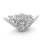
This chapter regards one specific element analysis of H.O.R.T.U.S. xl and H.O.R.T.U.S. neom.
The element in this analysis is the printing technique utilized for the projects. Both structure are composed of hexagonal pieces of 18cm radius that fits inside the build plate of the designed printing machine (wasp 4070 for both). Sequentially each of the hexagon is contoured creating a series of steps that become more visible with the curvature of the sculpture. Another important aspects of the two projects was it’s resolution to the nanometer. In both projects the steps measured 4mm, with a layer height of 1.2mm H.O.R.T.U.S xl accuracy on the end of the steps was not perfect, for 3 steps the print was ending after 8 layers and terminating in the exact position after the fourth, with hortus neom the level of accuracy was tuned to have a layer height of 0.4mm therefore each step consisted in ten layers. Following the technique I implemented the same concept in my structure, with a layer height of 0.4mm and a step of 4mm the precison of the printing was tuned to the limit.
The second aspect of the structure that I put in consideration was the infill. Both H.O.R.T.U.S. XL and neom were using a triangular infill thus creating an internal sub structure to both host the biopolimers and to support the steps of the structure. For the Carbon garden I decided to utilize another kind of infill, the gyroid. Due to it’s shape as a continuous surface the biopolimers will have various spaces to attach and live.
17
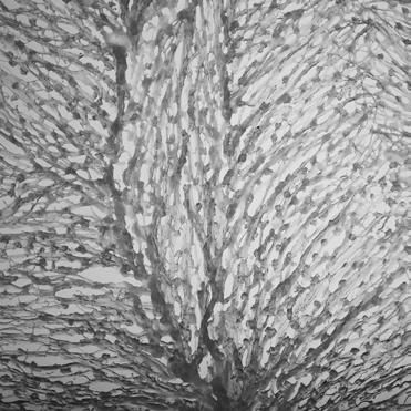
H.O.R.T.U.S xl Astaxanthin.g, EcoLogic Studio, La Fabrique du vivant, Paris 2018

TreeONE
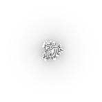
The elements that I took in consideration for this analysis of TreeONE are the use of a voxelization system and the printing utilizing algae infused bioplastic.
The voxelization utilized for the TreeONE is the result of a digitalization of a column into a point cloud, sequentially this digitalization is developed into a voxel system that generate the trunk of the TreeONE. From there a series of algorithmical process are executed to shape the outer shell of the sculpture.
The second aspects of TreeONE regarded the printing process, more in particular the utilization of an infused plastic. To 3D print the trunk of TreeONE the machine im plemented were robotic arms with a spawn of 3m height, the material in this case was recycled PLA. Its important to notice that during the printing process to apply a certain gradient to the structure the PLA was infused with algae powder. Thus, meaning that during the printing process the PLA was in a different format (pellets) and the spirulina organic powder was added while printing.
For the development of the Carbon Garden I took inspiration from the use of a vox elization to produce the structure, this time the starting geometry wasn’t a column but rather the mathematical model of cellular automata
19
TreeONE, EcoLogic Studio, Habitat One, Korea, 2022


[Master Seminar - Synthetic crystallisation II]
The last case study is dedicated to a course i took part as a student assistant. The course was divided into two compartments, the first one was the analysis fo a landscape on the alps and the second was a material experiment with bioplastic. The first step of the seminar was the development of a micro scale drawing of a glacier, this analysis was obtained trought flow algorithm and path systems. My role during this seminar was to help the students with their drawings leading them to understand the logic and the process of the algorithm and a first test for the creation of a stable Bioplastic.
The recipe was a mixture of : Starch, Glycerine Water and Vinegar. After several tries we obtained a stable product that could be utilized as material for the development of the study.
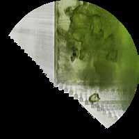
The use of bioplastic during this seminar was to act as a medium for the redescription of the landscape. The final output was the development of a large scale model produced with bioplastic.
On the left side is possible to observe the different steps of the process, the first image is one analysis of the territory triught a path system algorithm, the img n°2 rapresent the computized version of the model made with bioplastic. The actual model is displaced in the img n°3, its possible to observe in detail how the model was produced, same as in the drawings the bioplastic was layed on different lay ers, from there the layering of the material produced a three dimensional model. The last image shows the model after the bioplastic dired out. The material shrinked but the pattern produced remained creating a finall model of the landscape analysis.
21
Master Seminar - Synthetic crystallisation II, project led by Marco Poletto, photos by Korbinian Enzinger
CARBON SINK
23
03
 [Carbon Sink]
//To define the idea of carbon sinker we need to divide it into his fundamental part, therefore a carbon sinker is generally composed with two elements, the first one being an apparatus that absorb the carbon dioxide and metabolize it into organic matter, the second a host for the absorbed carbon dioxide and its products.
//The biggest carbon sinker on the planet can be considered the oceans who are responsible for ¼ of the carbon dioxide absorption and its metabolization. The ocean is not per se a carbon sinker rather the shell that host the above-mentioned apparatus. The organism that deals with the absorption and the metabolization of the carbon dioxide are the cyanobacteria’s that live the oceans.
//Cyanobacteria are most commonly known as green-blue algae. The organism survives thought the process of photosynthesis in which the carbon dioxide is absorbed from the environment and released as oxygen. During this process of carbon dioxide absorption and oxygen release the algae itself multiply producing new organic material, which at the end of the cycle sink into the bottom of the ocean.
//This process worked in a balanced environment for eons but of course as the technologies progressed the amount of carbon dioxide released by human activ ities has corrupted this balance, “the oceans are still executing their job as carbon sinker, but they are overburden with work, the amount of carbon dioxide absorbed and stored is endangering the ocean itself creating the phenomena of acidifica tion. The process happens because the oceans get in contact with more carbon dioxide producing more acid chemical components. After this event reached its peak, the balance went destroyed and the oceans acidification began.”
25
ESA, Cyanobacteria Satellite view
27 04
BIOPLASTIC


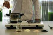


Production Layout Vinegar Additive [spirulina powder] Water Strach Wisk on high heat Glycerine Agar Agra Pour bioplastic
[Bioplastic production]
//The production of Bioplastic revolve around the use of biobased ingredients, the process here shown is the process to produce a biobased bioplastic with spirulina powder integrated.
//The process is a chemical reaction between the molecules of starch that bind togheter with the ones of the glycerine, the water works as a medium to dissolve both elements, vinegar is used as an activator for the process and ultimately AgarAgar is utilized as a stabilizer for the whole composition.
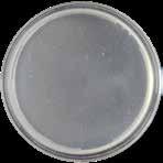
//The process starts with the addition of all the liquids therefore water, glycerine and vinegar are added, second all the powders starch (try to avoid lumps) agar agar and finally the additive of choice (in this case spirulina powder). The solution is than placed on a heater and heated while whisking it, once the water starts to evaporate the solution starts to solidify, after you reach the desired thickness its possible to fill a syringe and pour the bioplastic into a petri dish.
29


[1.1] Glycerine 0g [1.1] Glycerine 0g [1.2] Glycerine 5g [1.2] Glycerine 5g [1.3] Glycerine 10g [1.3] Glycerine 10g [1.4] Glycerine 20g [1.4] Glycerine 20g [01] Starch 6.5g Glycerine 0-20 ml Water 80ml Vinegar 15ml
[Bioplastic experiment 01]
// First test with bioplastic, the starting point of the experimentation was to use biobased and biodegradable material, the ingredients that are utilised are: Starch Glycerine Water Vinegar
// The first experimentation aimed to explore the optimal amount of glycerine for the bioplastic, during the test only this value has been altered duplicating it each step. The experiment revolved around the simplest recipe possible, that’s due to the fact that a simple recipee can be modified and developed with more success.
// The conclusion of this experiment resulted in a bioplastic that shrinked considera bly, the first experiment resulted in a fragile foil that broke, the same happened with experiment two and four but in this case the bioplastic didn’t broke due to fragility rather due to a quick cooling. On the other side the experiment three shrinked but didn’t breake, therefore the glycerien percentage resulted in the optimal amount.
31


[2.1] Starch 6.5g [2.1] Starch 6.5g [2.2] Starch 13g [2.2] Starch 13g [2.3] Starch 26g [2.3] Starch 26g [2.4] Starch 52g [2.4] Starch 52g
Starch 6.5-52g Glycerine 10 ml Water 80ml
15ml
[02]
Vinegar
[Bioplastic experiment 02]
//Second experiment with Bioplastic, this time the component that undergo the variation was the starch inside the recipe.
//The starch inside the recipe stiffens the composite. The amount of ingredients in the first experiment mathced the one of experiment 1.3 therefore the results as expected matched. In the second test the Bioplastic visibly shrinked but the ratio of glycerine and starch resulted in a mallable bioplastic. The same con be said to ex periment three, here it’s possible to notice a crack on the top side but the resulted bioplastic could be bented and resisted the opposing forces. The last experiment resulted instead in a bioplastic that didn’t performed well, the amount of starch in the mixture stiffned too much, and the resulting bioplstic couldn’t withstand any changes in it’s form.
33


Glycerine
[3.2] Glycerine 5g
[3.1] Glycerine 0g [3.1]
0g [3.2] Glycerine 5g
[3.3] Glycerine 10g [3.3] Glycerine 10g [3.4] Glycerine 20g [3.4] Glycerine 20g [03] Agar Agar 3g Glycerine 0-20ml Water 80ml
[Bioplastic experiment 03]
// Third experiment with bioplastic, this time without the use of sarch. The Biopoly mer used instead was Agar Agar, the powder is used in various fileld included the kitchen in which is mixed with water to create gelly. Said so the addition of glycer ine allows the bioplastic to be more solid working as an aggregant for the molecule structure.
// This experiment was designed to introduce the Agar Agar inside the bioplastic recipee. This mixture provides to the bioplastic with more plasticity. As possible to observe the bioplastic developed some fungi on it’s surface, the agar agar provid ed a new fature but at the same time it became the host for a non-human activity.
// It’s possible to observe that the experiment number four the glycerine amount prevented the formation of fungi on the surface.
35
[04]
Starch 13-26g Glycerine 10ml Water 80ml Vinegar 15ml Agar Agar 3g


[4.1] Starch 13g
[4.2] Starch 26g
[4.1] Starch 13g
[4.2] Starch 26g
[Bioplastic experiment 04]
//Fourth experiment with bioplstic, this time the experiment merged all the previuos experience into one recipe. This time to explore the starch and its interaction with the other components the value is changed taking the two best value obtained with the previous experiments.
//This time the bioplastic reacted in an optimal way, the first experiment with less starch shrinked a little bit more than the second one with more starch in it. On the other side the flexibility of the bioplastic was inverted, the one with more starch resulted more stiff whyle the other one mantained its flexibility.
//The conclusion of this experiments resulted in an analysis of different recipee with bioplastic that culminate in two optimal sample. Therefore the experiments contin ue in the second phase of the optimisation in which “alien“ additives will be added inside the bioplastic to test its hospitality.
37
[05]
Starch 13g Glycerine 10ml Water 80ml Vinegar 15ml Agar Agar 3g Coffee 15-30g


[5.1] Coffee 15g [5.1] Coffee 15g [5.2] Coffee 30g [5.2] Coffee 30g
[Bioplastic experiment 05]
//Fifth experiment with bioplastic, this time with the introduction of an alien addi tive, this time the additive choose is used coffee.
//The bioplastic produced with coffee became very stiff, the addition of a powder as coffe worked with the same logic of the addition of too much starch, the liquid molecule are trapped inside the starch and coffee molecules therefore the sub structure produced result in a denser bioplastic.
39
Starch 13g Glycerine 10ml Water 80ml Vinegar 15ml Agar Agar 3g

Starch 13g Glycerine 10ml Water 80ml Vinegar 15ml Agar Agar 3g Sawdust 15g


Starch 13g Glycerine 10ml Water 80ml Vinegar 15ml Agar Agar 3g Paperpulp 15g

[09]
Starch 13g Glycerine 10ml Water 80ml Vinegar 15ml Agar Agar 3g Seeds

[6.1] Organic Powder 3g [6.1] Organic Powder 3g [7.1] Sawdust 15g [7.1] Sawdust 15g
[06]
Powder
Organic
3g [07]
[8.1] Paper Pulp 15g [8.1] Paper Pulp 15g [9.1] Seeds [9.1] Seeds
[08]
[Bioplastic experiment 06-07-08-09]
//With this series of experiment i continued the testing of “alien“ additives inside the bioplastic. At first i added organic powder from organic waste like orange peel, the result ended with a bioplastic with a stable consistency but the overall stifness wasn’t satisfying enought.
//For the experiment 07 i added another tipe of organic waste, in this case the ad ditive was sawdust. Symilar to the coffee the sawdust absorbed the mixture within it’s fibers creating a very stable bioplastic with limited shrinking but also limited flex ibility.
//The experiment 08 similar to experiment 07 utilized a very abundant waste mate rial such as paperpulp, the paper is shredded and soaked in water. This experiment had almost the opposite result of experiment 07 in fact even though the fibers ab sorbed the mixture the bioplastic shrinked consistently but obtained an impressive flexibility.
//The experiment 09 integrate another kind of additive this time not to test the changes of the bioplastic but rather to test if biological being can survive inside the bioplastic.
41


[10]
[10.1] Spirulina Powder 15g [10.1] Spirulina Powder 15g [10.2] Spirulina Powder 30g [10.2] Spirulina Powder 30g
Starch 13g Glycerine 10ml Water 80ml Vinegar 15ml Agar Agar 3g SpirulinaPowder 15-30g
[Bioplastic experiment 10]
//The last experiment of this series revolved around the final additives introduced inside the bioplastic, a fine powder of spirulina powder is introduced.
//The amount of powder changed from 15 to 30g, the first experiment resolved into a stable bioplastic with good plasticity that did’t shrunk too much and that when dried dind’t broke. The second one with more powder ended to be too soft and fragile therefore after the drying the bioplastic felt apart.
// The aim for this part was in fact to test the changes inside the bioplastic with different organic materials. This step allowed us to progress torught the project and to ensure the ability of bioplastic to host materials that doesn’t chemically belong to the bioplastic. During those test the bioplastic behaviour changed radically, sometime in a pos itive way and in other cases in a more negative. Adding fibrous material like the Coffee [5.1-5.2] made the bioplastic more sturdy whyle when adding the paper pulp [9.1] the bioplastic became very malleable and elastic.On the other side when a component like orange peel [06] was added the bioplastic qualities de creased makeing it more brittle and fragileThe sperimentation was foundamental for the sake of the artificial carbon sinker since this will be contain within itself the organic matter produced by the cyanobacterias
43
05 TERRAIN ANALYSIS
45

[City Mapping]
Innsbruck
//The beginning of the city mapping for my project begins with an analysis over the city of Innsbruck. The decision for this is due to the familiarity with the environment.
//The city is located in the West of Ausrtria, the city is surrounded by the Alps on the north and south side and crossed by the Inn river wich flows from east to west whyle .
//The study of the city starts with a terrain analysis in which the city is connected with the river, thus locating the optimal position to host the project
47

[City Analysis]
//The city analysis connecting the city to the rive.
//As oreviously said this analysis is developed to find the location of the project.
49

[City Mapping]
Colour coding
//The second analysis of the city is designed to extract trought color couding two aspects of the environment, the photosynthetic and the biosphere, both elements are deeply connected to the project. The first one rapresenting all the organism that produce oxigen trought photosynthesis on land and the second one rapre senting the organism that produce oxygen under water.
//From there the single elements are analyzed not anymore as images but are translated into pixels to be mathematically described and analyzed. A new path system is produced connecting the hotspot to the city on this new landscape.
51


[City Mapping - colour coding]
[Zoom in - photosynthetic]
//The colours are reversed from their original on the visible spectrum. In black it’s possible to observe the areas witouth any kind of vegetation, thus the streets of the city and the peak of the mountains.
//The first colour coding analysis is produced by isolating the photosynthetic.
//The colour coding analysis is designed to be re-analyzed into a mathematical model made with pixel.
55

[City Mapping - colour coding]
//The first analysis led to a new type of math ematical environment. This process loses the high definition of a satelite image but can produce a much more understandable environment thought a mathematical enhancment.
57


[City Mapping - colour coding]
[Zoom in - Hydrosphere]
//Same as the photosynthetic also the hydropshere is colour coded in the same way isolating it from the rest of the environment
//In this case the urban environment of concrete and buildings is colourcoded using yellow, in a gradient of sea-green the whole photosynthetic is mapped without any enhancment, finally the hydrosphere is colour-coded to its opposite (pink) to accentuate its presence. Its possible to observe how the colour-coding affected the river crossing the city but also the glaciers surrounding the city.
61

[City Mapping - colour coding]
//Same as the photosynthetic the colour coding is re-analyzed with this pixel model.
63

[City Mapping - colour coding]
//The two analyzed components are over lapped into a new landscape.
65

[City Mapping - colour coding]
//The final analysis is generated, but this time the path system is reversed, from the hotspot the algorithm extend to reach the city cre ating a circular exchange of information between the city hotspot and viceversa.
67
06 CELLULAR AUTOMATA
69


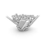
[Cellular Automata]
//A Cellular Automata is a collection of colored cells or atoms on a grid of a spec ified shape. Each cell is in one of a finite number of states. As a result, the evolu tion of the CA through several discrete time steps occurs based on a set of rules founded on the states of neighbor cells. These rules can be iteratively applied for as many time steps as required. The cells in a CA reside on a grid which has a specified shape and exist in a finite number of dimensions. Each cell on the grid has a state. While there are numerous finite possibilities of the state, the simplest state form is usually ON or OFF. The cells adjacent to one cell constitute its neighborhood. Cells in a neighborhood affect each other, and each cell on the CA grid has a neigh borhood.
//Those immages rapresent the logic of the CA, the img. n°1 rapresent the starting cells of the CA. Img. n°2 rapresent the number of neighbor checked by the algo rithm, in this case the rule was designed to accept only points with neightbours between 2 and 3. Img. n°3 on the other side checks for points that should have died for overpopulation and allows them to the next level, in this case the rule was set to 3. The img n°4 rapresent the combination of the rules and therefore the next set of points. This new set of points is than re-analyzed with the same set of rules produc ing the final geometry of the cellular automata.
71
2 neightbour check :True


3 neightbour check :False neightbour to survive : 2


2 neightbour check :True 4 neightbour check :False neightbour to survive : 2

2 neightbour check :True 4 neightbour check :False neightbour to survive : 3
2 neightbour check :True 4 neightbour check :False neightbour to survive : 4
2 neightbour check :True


5 neightbour check :False neightbour to survive : 2

3 neightbour check :True 5 neightbour check :False neightbour to survive : 2
6 neightbour check :True 8 neightbour check :False neightbour to survive : 2
7 neightbour check :True 8 neightbour check :False neightbour to survive : 2


73
2 neightbour check :True


3 neightbour check :False neightbour to survive : 2


2 neightbour check :True 4 neightbour check :False neightbour to survive : 2
2 neightbour check :True 4 neightbour check :False neightbour to survive : 3
2 neightbour check :True 4 neightbour check :False neightbour to survive : 4
2 neightbour check :True


5 neightbour check :False neightbour to survive : 2


3 neightbour check :True 5 neightbour check :False neightbour to survive : 2
6 neightbour check :True 8 neightbour check :False neightbour to survive : 2
7 neightbour check :True 8 neightbour check :False neightbour to survive : 2


75


[Cellular Automata]
Process
//The four images here rapresent the creation of the voxelisation for the artificial carbon sinker structure. From the satelite image of the hotspot a pixelisation algor tihm is developed, the algorithm translate the image into a series of pixel that are coloured in a gradient from black to white. On the img n°3 the sorting algorithm sort a certain type of pixel based on the decided colour. The final image n°4 is the result of the cellular automata obtained with the starting points mapped from the hotspot location.
77
07 CARBON GARDEN
79

[Carbon GARDEN]
//The final proposal for my project is the carbon garden, an artificial carbon sinker produced with waste material from the cyanobacteria integrated inside the bioplastic. The carbon garden is the result of my experience during my years as a student assistant for SLL and EcoLogicstudio, the structure will integrate a series of bioreactors that will clean the air and at the same time the structure will be manufactured using the waste materials of those. Trought the bioplastic experimentation it was possible to observe how the bioplastic reacts to different alien material integrated in it.
// The aim of the project was to find a new relationship between the bioplastic and the carbon sinking process. This interaction of two apparatus generates a new kind of architectural system, not anymore human based but rather non-human based. The carbon garden is an artificial carbon sinker that lose its form and became a new type of garden for the non-human organism to live. The structure will be the byproduct of the carbon sinking, effectively producing a new material system for the construction of infrastructures or buildings that can integrate non-human or ganism to reduce their carbon impact on the planet.
81


[top view] Triangle infill 20% [Test 01] [Detail] Triangle infill 20% [top view] Cross infill 20% [Test 03] [Detail] Cross infill 20% [top view] Grid infill 20% [Test 02] [Detail] Grid infill 20% [top view] Gyroid infill 10% [Test 04] [Detail] Gyroid infill 10% [top view] Lightning infill 10% [Test 05] [Detail] Lightning infill 10%
[Carbon sink cell infill tests]
//The test on the cell infill started on a smaller scale component.
//Test 01 utilized the same infill as hortus, the triangular ones. The structure itself has strong compression resistance. Also on lower densties the infill can support the structure for a perfect component.
//Test02 utilized the grid infill, this infill similar as the triangular one has strong compression resistance but with the same density as the triangular ones the priniting process was altered due to the large spaces in betweenthat didn’t sup port the structure enough
//Test03 the cross infill utilize a large area and a good support for the print itself with different variation angle.
//Test04 the gyroid infill was by far the most resistant in both compression and tension, the sturcture with it’s continous void create an intriguing geometry for the bioplastic to explore
//Tets05 the lightning infill is designed to work at the same time as inffi and support, the infill developes and spread into different direction with the growth, unluckly this function didn’t produced the expected results and produced a bad quality print
85


[Detail] Gyroid infill 20% 40mm [Detail] Gyroid infill 20% 10mm [Detail] Gyroid infill 20% 20mm
[Carbon sink cell infill tests]
//A new series of experiment is conducted on the gyroid infill, this time to explore it’s features.
//The gyroid is a minimal surface described by the following mathematical formula : sinxcosy+sinycosz+sinzcosx=0.
Due to it’s conformation the gyroid doesn’t have a clear distinction between inside and outside, therefore when integrated in a shell the material inside is free to self arrange itself inside the structure.
//This series of experiment explore the fabrication of one component, combining the research on H.O.R.T.U.S. XL and neom, utilizing the nozzle of the fist combined with the precision of the second one.

[Carbon sink cell]
//The cells composition in all its components will work as a carbon sink.
//The outside of the structure is designed as the H.O.R.T.U.S xl and H.O.R.T.U.S neom, contouring the structure each 4mm the lines are sequentially extruded to define the external component ond the structure. The openings on the structure will work as aereation opening to let CO2 flow trought.
//The inside of the structure that will hold the bioplastic within itself is a gyroid infill, the infill has different notable advantage. The gyroid infill can withstand the different applied forces in all directions thanks to it’s continous form, the second one that much relate on the core aspect of the project is it’s hollow spaces that can trap bioplastic inside.
89

3D-Printed Component
//First module of the Carbon Garden. The piece follows the same printing technique as H.O.R.T.U.S. xl and Neom.
//This piece was printed with a 0.4 nozzle to take advantage of the experience with H.O.R.T.U.S. neom, therefore the 4mm steps are accuratly printed every time.
91

Inoculation
//The first module is filled with biogel, the technique utilized revolved around the use of a compressor to extrude the biogel in position.
//The use of the Gyroid infill with his continous surface connects all the cells, therefore when filling it the biogel was expanding to the adjacent cells. This allows for a more natural distribution of the biomass that is not constricted and forced into one single unit but has the freedom to self distribute inside the sculpture.
93


[Carbon Garden as a landscape]
//This final chapter revolve around the vision of the carbon garden. This drawing explore the development of the structure as a landscape.
//The scaling of one component into a landscape size structure is the result of a carbon absorption calculation. The city of innsbruck has a annual carbon dioxide emission of 405500 Ton therefore starting from the single component the volume of the structure to be able to absorbe all the carbon dioxide reach the 2.2 M m3.

The gyroid starts to merge with the actual landscape generating a new kind of land scape that developes inside the carbon garden layered structure.

The carbon diagram merges with the path system developed on the carbon garden. The system ridistribute the absorbed carbon dioxide inside the structure.

[Carbon Garden as a landscape]
//This drawing aim to explore the behaviour of the structure in a landscape.
//The Gyroid inside become the support structure to hold the carbon cells filled with biogel to operate as carbon sequestrator. As previously mentioned the gyroid infill without a clear separation between inside and outside became the new landscape able to host non-human and human activities.

[Carbon Garden as a landscape]
//This final diagram shows the behaviour of the new discovered landscape inside the structure. The gyroid behave as a substructure to host the carbon sequestrator component responsible for the photosynthesis.
//The second aspect of this diagram is displaced by the orange path system that is responsible to redistribute the absorbed carbon from the city inside the structure. The path system connect each of the spheres and allows the components to perform the carbon sequestration.
107
08
APPENDIX

[HORTUS XL and HORTUS NEOM]
Analysis
HORTUS XL is a project developed by ecologic studio in 2018 in collaboration with the SLL. In 2021 HORTUS XL was developed further into a smaller version for a private client. During both project I was assigned the task to prepare the gcodes, print the components and occasionally repairing tuning the printer. The first iteration of HORTUS was composed of 79 pieces, the sculpture measured 1500mm in depth, 2700mm in length and 3100mm in height. The first point of this analysis regards the settings for the printing process.
HORTUS XL was splitted into hexagonal component that would perfectly fit inside the build plate of the machine used, a WASP 4070 Industrial with a delta print ing technology, therefore the hexagons measured 18cm in radius with a variable height from 200mm to 900mm, the bigger piece where ultimately splitter into two components for printing’s sake. The HORTUS XL is the result of a territorial analysis that’s processed into a three-dimensional geometry, sequentially the structure is contoured with a height of 4mm creating the actual shape of the sculpture. During the first HORTUS XL print its important to notice the dimension of the nozzle, in fact the structure is printed with one of the largest nozzles possible a 1.2mm. The big nozzle translates into a faster print with higher layers, and more strength, moreover, to increase this aspect the layer thickness was increased even further to 1.4mm to have thicker layers for a better wall strength.
H.O.R.T.U.S xl Astaxanthin.g, EcoLogic Studio, La Fabrique du vivant, Paris 2018


111
The wall of hortus were kept with a single unit to empathize its internal structure and transparency, it’s notable that during the printing process whenever the speed of the printing was decreased by a couple of mm/s its immediately possible to notice a change in the transparency. The internal structure of HORTUS XL was endlessly not designed but rather entrusted to the program, in fact the triangulation of 46mm inside the components is the infill calculated by the program, the brilliant idea in this case was to remove both the top and the bottom layer to obtain an open component in which the biogel medium could be inoculated. The dimensions of the infill were assigned by density, 20% in this case, obtaining as said triangles with a side of 46mm.
The printing of hortus was by no mean a simple process, due to the above-men tioned settings of infill and porosity each piece had to be rotated 90° on the X axes to align the infill, therefore supports were needed on most of the components. When speaking of 3D printing the addition of supports always means bad news, in fact with the time also the eventuality of failure increase. With HORTUS we man aged to set the minimum amount of supports needed to 3D print and only printing support that started from the build plate, in rare occasion where the cavities where we designed ad hoc support in specific positions.
Left: H.O.R.T.U.S xl Astaxanthin.g, EcoLogic Studio, La Fabrique du vivant, Paris, 2018
Right: H.O.R.T.U.S Neom, EcoLogic Studio, Private collection, 2021
The finals settings for HORTUS revolved around the most important layer, the first one. From that one its possible to understand the outcome of the print, the lay er needs to be perfect in all the aspects, from its thickness to its adhesion to the build plate, the thickness of it is controlled during the leveling of the machine and running a quick test before printing the actual piece saved many failures. For the adhesion we applied a brim to all the piece, a brim is a concentric offset of the first layer external line that allows the piece to be connected to a substantial bigger area rather than only on the edge of the first one, this method was even more im portant for Hortus since the amount of walls was kept to one.
The second development of HORTUS implied the extraction of a portion of around 20 components. For the second coming of HORTUS we decided to tune all the settings to reach the peak performance of the machine. The second HORTUS was printed with a classic 0.4mm nozzle, the decreasing of the nozzle size meant a more detailed and fine printing process, but other aspects needed to be optimized, for example the number of walls, utilizing 0.4mm the thickness of the walls was to brittle and could break, therefore we tuned the number to three to achieve the same thickness of the first HORTUS.
113
Another important aspect that was peakly tuned was the layer height. In this sec ond development with a smaller nozzle we could control every little detail there fore the amount of layers per step was calculated to match the end and the be ginning, each step measured therefore a total of ten layers. Another important improvement was applied to the infill, this time the artwork was smaller and finer therefore each detail was noticeable, the infill was tuned to be a prolongation of the adjacent components in a precision of ± 0.1mm, creating a perfect continuity between the pieces. An important fact in this project is that even thought most of the pieces were print ed at SSL in Innsbruck a few were commissioned to an external manufacturer, this was due to the limited time for the production, therefore all this fine tuning settings needed to be shared and explained to the externals to achieve the same exact result even on different machines. A final fact of this HORTUS revolve around its assembly and inoculation. This time the sculpture didn’t traveled in separate clusters but as a whole piece, so the method to connect the pieces was a specific glue to weld together the pieces. Regarding the inoculation we tested a new technique, the technique revolved around the use of the clay printing equipment of the WASP 4070, filling the printing chamber with the biogel and a compressor to compress it we were able to fill the hortus in more components at the same time.

Analysis
TreeONE has been exhibited at the Hyundai motor center in Busan (South Korea) For this project I worked on the design part and the 3d printing process. These two elements are strictly connected between each other. TreeONE starts with the geometry of the Corinthian column, the primitive form for the shelter. The project itself begin with the analysis of a point cloud of a column and it’s development therefore the trunk of a column merge together with the processed canopy of the capital. The point cloud is processed to create a voxelization of the geometry, the dimension of the voxel are 75mm, creating a base area of 3 square meters, but more amusing is the vertical spawn. The TreeONE would have been placed inside the car lift of the building, stretching from the ground floor up to the first. From the deign of the voxel of TreeONE a path system is designed to run from the roots all the way to the canopy, creating the actual design for the TreeONE. The first design of the TreeONE (formerly SuperTREE) revolved around the creation of a substructure from the edges of the voxelization and the inflation of the algorith mic path, the substructure would have been the support and simultaneously being the artwork. The first approach for this TreeONE version we tested the possibility to apply one peculiar technique of 3D printing called wire-print. The wire-print utilize the wireframe of the geometry and use it as the printing path. To test this hypothe sis we discussed with a local printing factory, as first approach the technique was doable but due to the big spawn of the tree and it’s complexity the production would have been impossible.
[TreeONE]
TreeONE, EcoLogic Studio, Habitat One, Korea, 2022


117
As second approach the structure was undraped of it’s substructure to leave only the path system, this system was than thickened algorithmically, the thickness pro cess count the amount of segments that follow the same path and enlarge the line accordingly, counting the 75mm of the voxel we decided to set the maximal radius to 25mm therefore the fibers of the tree will be spaced 25mm too. To create this second design of TreeONE we planned to 3D print all the components, to execute this plan we considered three different possibilities.
The 10m of the TreeONE were divided into different components according to the maximal dimension of the available 3D printers. The first series of subdivision took in consideration the dimension of a WASP4070 Industrial, the same one of the H.O.R.T.U.S xl Project, therefore a circular bed with the diameter of 400mm and the height on 700mm. Unlucky the amounts of component range around 800 therefore the production would last 3-4 months with continuous printing 7/7 24h/24h.
The second approach was to utilize the biggest printer available to WASP the WASP3mt, this printer designed for large scale model can print on a circular bed with 1000mm of diameter for 1000m height. Through this option the amount of piec es decreased from 800 to around 50. The technical difficulties didn’t end with the reduction of the components, the fib ers of the tree were too horizontal causing the necessity of supports everywhere in creasing even more the amount of time and for post processing the components, to minimize this inconvenience the smooth fibers were curved by a degree of 5 pushing their inclination to 45° which is possible to print with relative ease on every machine. This option seemed more valuable but the time for the printing didn’t change drastically even though the components were 1/16 of the original ones. That’s because the amount of material and “street” for the printer to perform didn’t change. Therefore we needed a new solution for the Project. The last and final ap proach revolved around the re-design of the trunk of the TreeONE, the last avaible option consisted in the vase mode technique. A 3d Printing method in which the machine path is always starting and ending in the same position without the need to travel across the build plate. This allows the machine to print at a considerable faster speed. Regarding the Canopy of the TreeONE the design decision was to proceed with the classic 3D printing technique. The amount of pieces were considerably re duced and printed on larger machines (1200*1200*1300).
119
The redesign of the trunk started from the path system of the digital model. The fibers of the path system were contoured each 75mm starting from 37.5mm above the base, this allowed the contour to avoid all the Horizontal fibers inside the path system. From there to simulate the original fibers of the tree a weaving technique is applied. The point from the contour (representing the original fibers) were copied in the inside by 75mm and shifted clockwise by 37.5mm, than a series of circle is placed for each point and connected through internal tangents. This method was designed across the 8100mm of the trunk of TreeONE, the model was further de veloped in cooperation with the manufacturer, the machines still have their limits regarding the horizontal spawn, to secure a smooth print minimizing the possible errors.
The material designed for this artwork was a recycled PLA, in this case the mate rial was very important, since the printed utilized for the trunk was a robotic arm feeded with PLA pellets it was possible to insert additives during the printing, in this case the additive was spirulina powder. The dark green powder was utilized to design a diagram on the whole length of the trunk, the diagram in question was the percentage of pollution from the beginning of the project to the start of the production. The line was divided into different segments (27) and translated into percentage base of the RBG color that was detected by the algorithm.
121
123
I want to dedicate this project to all the people who helped me during this period.
I wish to express my sincere thanks to Univ. Prof. Claudia Pasquero who supervised the project for the patience and the continous encouragment.
Special thanks to all the Architecture Faculty of Innsbruck, in particular to : Maria Kuptsova who co-supervised the project, Korbinian Enzinger, Terezia Greskova and Haoyi Chen for the inexhaustible support.
Lastly, I take the opportunity to deeply thank my family for alwyas beliving in me, Martina Zanol for alwyas being by my side, and all my friends for their unquestionable friendhsips.
Your help made all the difference. Thank you
125
IOUD Synthetic Landscape Lab
University of Innsbruck Supervisor: Univ. Prof. Claudia Pasquero Co-Supervisor: Maria Kuptsova, MA Korbinian Ezinger, Dipl. Ing Terezia Greskova, MA
University of Innsbruck - Faculty of Architecture - IOUD Synthetic Landscape


