If this document has become partially or completely unusable, you can request a replacement via info@fliegl.com The document is also available for download online.
Read these operating instructions prior to first-time start-up and observe them at all times!
Retain for future reference! Lost or illegible operating instructions must be replaced immediately.
Foreword
Dear valued customer,
Thank you for purchasing the Fliegl trailer.
Fliegl vehicles and attachments are manufactured with care under continuous monitoring. The Fliegl trailer you have purchased is a product manufactured to the highest quality standards.
To avoid accidents, and therefore personal injuries and material damage, you must read and understand the corresponding cautionary and warning notices in these operating instructions and on the Fliegl trailer before beginning operation or maintenance of the trailer. These operating instructions must therefore also be passed on to the operating personnel.
Before putting the Fliegl trailer into operation, every operator must be familiar with how to handle the vehicle as described in these operating instructions. The safety requirements must be strictly followed. The applicable safety regulations for your country must also be observed.
The limits of use are described in this manual. Any types of operation or use other than those described in these operating instructions or beyond the limits of use specified by the manufacturer are strictly prohibited
3.6.4
Legal notices
1. When the vehicle is delivered, check immediately to determine whether it is complete. Upon receipt, you should also check the vehicle for signs of transport damage. State any complaints to the freight forwarder and/or dealer, have them certified on the delivery documents and inform the delivering plant within a period of 14 days (see "Scope of delivery").
2. The manufacturer is liable for technical defects. The owner is liable for defects that were caused by improper operation. The warranty period is 1 year from delivery.
3. At our discretion, the warranty will either cover the cost of repair or replacement of the faulty part or delivery of the part from the factory, carriage due. Any other claims for compensation (such as for losses due to business interruption) are expressly excluded.
4. The warranty will be invalidated if the vehicle is modified by installing third-party parts without our knowledge or prior agreement, especially if improper modifications were made.
5. The warranty will also be invalidated if a defect is not rectified completely and correctly immediately after it is discovered. Repairs required for functional reasons need our prior approval if a claim is to be made for full or partial compensation of expenses.
6. Liability is excluded for damage to the vehicle resulting from exceeding the allowable working capacity or transport speed. The warranty does not cover natural wear, damage resulting from negligent or improper handling of the device, or storage and corrosion damage.
7. Parts not manufactured by us are covered by the warranty provided by the relevant manufacturer. Device parts for which claims are made under the terms of the warranty must be sent without delay to our address in Mühldorf for the purpose of material examination or to determine the damage. If a replacement is made, these parts become our property.
8. Legal warranty provisions also apply to the vehicle.
Identification
Identification
Identification data
Manufacturer: Fliegl Agrartechnik GmbH
Product: Push-off semi-trailer
Type:
• ASS 272
• ASS 372
• ASS 377
• ASS 382
• ASS 477
Serial number: WGJXXXXXXXXXXXXXX
Manufacturer data Sales
Fliegl Agrartechnik GmbH
Bürgermeister-Boch-Straße 1
Fliegl Bau - & Kommunaltechnik GmbH
Bürgermeister-Boch-Straße 1 84453 Mühldorf am Inn, Germany 84453 Mühldorf am Inn, Germany
Tel.: +49 (0)8631 307- 0
Fax: +49 (0)8631 307 - 550
E-mail: info@fliegl.com
Website: www.fliegl.com
Formal details of operating instructions
Tel.: +49 (0)8631 307 - 381
Fax: +49 (0)8631 307 - 553
E-mail: baukom@fliegl.com
Website: www.fliegl-baukom.de
Document no.: 4-303B10223.1
Version/revision: 3.1
Creation date: 15/02/2015
Last revision: 14/11/2023
Language of original operating instructions: German (Translation of original operating instructions)
Copyright Fliegl Agrartechnik GmbH, 2023. All rights reserved. Reproduction, in whole or in part, is permitted only with the approval of Fliegl Agrartechnik GmbH.
We are constantly developing and enhancing our products and therefore reserve the right to make changes to them without prior notification. This may result in differences in the illustrations and descriptions in these operating instructions.
All brand and product names are trademarks or registered trademarks of the relevant title holders.
EC Declaration of Conformity
In accordance with the EC Machinery Directive 2006/42/EC, Annex II, 1.A (ORIGINAL)
Manufacturer:
Fliegl Agrartechnik GmbH
Bürgermeister-Boch-Straße 1 84453 Mühldorf am Inn, Germany
Person residing in the European Community authorised to compile the relevant technical documentation:
Josef Fliegl jun.
Managing director
Fliegl Agrartechnik GmbH
Bürgermeister-Boch-Straße 1 84453 Mühldorf am Inn, Germany
Description and identification of the vehicle Product: Push-off semi-trailer
Type: ASS 272, ASS 272 Compact, ASS 372, ASS 372 Mega, ASS 377, ASS 377 extra long, ASS 377 extra long – telescopic, ASS 382, ASS 477 4-axle Quad extra long – telescopic
Trade name: Fliegl push-off semi-trailer
Function: Transport trailer with sliding unit
It is expressly stated that this machine complies with all relevant provisions:
The harmonised standard EN ISO 14982:2009 was used within the meaning of the Directive.
Source of the harmonised standards applied in accordance with Article 7(2):
ISO 12100:2010 Safety of machinery – General principles for design – Risk assessment and risk reduction
Mühldorf am Inn
14/11/2023
Place Date
1.User instructions
This manual provides information about the:
• Layout
• Function
• Operation
• Maintenance
• Accessory parts of the vehicle and ensures long, problem-free operation if it is carefully observed. In case of malfunctions, it can be used to troubleshoot and rectify faults. The purpose of the safety instructions is to prevent personal injury and damage to the vehicle. All operators are required to read these safety instructions and comply with them at all times. The regulations of the employers' liability insurance associations for the construction industry also apply. Fliegl Agrartechnik GmbH assumes no liability and honours no warranty for damage and malfunctions resulting from failure to comply with the operating instructions.
This information is required to ensure a smooth replacement parts ordering process:
Copy the relevant information from the type plate into the box below:
Vehicle ID no.
(serial number)
Year of manufacture / model year
Contact for service, warranty and replacement part orders
Fliegl Bau & Kommunaltechnik GmbH
Service Department
Bürgermeister-Boch-Straße 1 84453 Mühldorf am Inn, Germany
Replacement parts must satisfy the technical requirements stipulated by the vehicle manufacturer as a minimum. This requirement is always met when using Fliegl original replacement parts.
1.1 Purpose of this document
These operating instructions:
• Describe the function, operation and maintenance of the vehicle
• Provide important advice for safe and efficient working with the vehicle
• They help to:
o Avoid damage and dangers
o Minimise repairs and downtimes
o Maximise the reliability and service life of the vehicle
1.2 Scope of the document
In addition to the standard models, B variants of the vehicle are also described in this document. Your vehicle may deviate from this.
1.3 Other applicable documents
Accurate knowledge of the individual components is required to ensure safe and trouble-free operation of the vehicle. Compliance with supplementary documents to these operating instructions is therefore essential.
The following additional documents must be observed, in particular the safety information:
• Operating instructions of the towing vehicle
• All instructions for additional components and assemblies
• All instructions for optional equipment
• If instructions are lost or become illegible, they must be re-ordered or replaced.
The following must also be observed when using the vehicle and during all maintenance activities:
• Maintenance specifications for the relevant supplied components
• Load securing regulations
1.4 Document storage
• These operating instructions must be stored safely along with all other applicable documentation.
• The complete documentation must be passed on to future drivers or owners.
1.5
Illustrations used
Instructions and system responses
The steps to be taken by operating personnel are presented in the form of a (numbered) list. These steps must be followed in the correct order. The system response to each operator action is marked with an arrow. Example:
Operator action step 1
➔ System response to operator action step 1
1.6 Cross references
Cross references to other points in the operating instructions appear in the text along with the relevant chapter and subchapter or section.
1.7 Terminology: "trailer", "vehicle"
Within this document, the Fliegl vehicle type is also referred to as the "trailer" or "vehicle".
1.8
Figures
The figures in this document do not always depict the exact vehicle type. The information relating to the figures always corresponds to the vehicle type described in this document.
1.9 Locations in the operating instructions
All directions and locations in these instructions are based on the operator's workstation.
1.10 Presentation of safety instructions
Danger! Imminent risk that will lead to serious bodily harm or death.
Warning! Potentially hazardous situation that could lead to serious bodily harm or death.
Caution!
Notice!
Potentially hazardous situation that could lead to minor bodily harm. Also warns against potential damage to property.
Potentially harmful situation in which the product or other property in its vicinity could be damaged.
Important! For usage instructions and other helpful information.
1.11 Liability and damages
The product must only be operated by persons who are familiar with the operating instructions and the product along with the national laws, directives and regulations relating to occupational health and safety as well as accident prevention. We accept no liability for personal injury or material damage caused, or contributed to, by untrained persons due to non-compliance with regulations regarding occupational health and safety as well as accident prevention.
Based on the specifications in these operating instructions, Fliegl Agrartechnik GmbH assumes no liability for direct or consequential damage attributable to improper operation or maintenance. For your own safety, you must use only original replacement parts and accessory products. Fliegl Agrartechnik GmbH assumes no liability for the use of other products and any resulting damage. No claims for modification of delivered products can be made on the basis of the information, images and descriptions provided in this manual.
1.12 Duty to inform
These operating instructions are to be considered part of the vehicle. If the vehicle is passed on to another party by the customer, the operating instructions must also be passed on, and the party receiving the vehicle must be instructed regarding the specified regulations. Only the procedures described in these operating instructions are safe.
• Read and observe the contents of chapter 2 Safety instructions before first using the vehicle.
• Before commencing work, always read and observe the contents of the relevant sections of the operating instructions.
• The operating instructions must be stored such that they are always ready to hand for the vehicle user.
• These operating instructions must be stored safely along with all other applicable documentation. Replace the operating instructions if they should become illegible.
German Equipment and Product Safety Act (GPSG): In sections 4(4)(1) and 4(4)(2), the transfer of the operating instructions is regulated by law
1.13 Notes regarding legal regulations
With regard to legal requirements, the vehicle is manufactured according to the regulations valid on the day of delivery.
• The owner must ensure that all routine statutory inspections are carried out in line with national regulations.
• The owner must also ensure compliance with all legally prescribed weights, axle and drawbar loads as well as dimensions.
Any modifications to the vehicle that deviate from the specifications in the permit documents will invalidate the operating licence.
• No unauthorised modifications or manipulations on the part of the owner must take place.
• Necessary, permitted vehicle modifications must be entered in the registration document by a certified inspection authority.
• Use only correct and permissible tyres.
• Use only suitable and permissible original spare parts.
1.14 Delivery of the vehicles
A first-time start up takes place in the factory prior to delivery. The vehicle is primarily delivered via a dealer or directly from the factory.
• The vehicle recipient must ensure that the transferred documentation is complete.
• The recipient must be instructed in how to operate the vehicle.
• The vehicle must be collected with a suitable towing vehicle.
2.Safety instructions
Failure to observe the safety instructions and warnings can pose a risk to persons, property and the environment. Non-compliance can also result in the loss of any claims for damage compensation on the part of the customer.
When driving on public roads, be aware of the following: When driving on public roads, the provisions of the country-specific registration regulations must be observed.
The operator is personally responsible for the registration of the vehicle.
Lost permit documents can only be replaced by agreement with the administrative/regulatory authority specified below. A duplicate of the permit documents will be given to the customer by the administrative/regulatory authority.
A duplicate of the CoC document (Certificate of Conformity) can be issued by the manufacturer.
These operating instructions contain information to ensure your personal safety and safe use of the vehicle. These basic safety instructions contain information to ensure safe use and maintenance of the vehicle. The relevant safety instructions warn of residual dangers and precede any hazardous work steps.
All instructions must be observed to prevent personal injury as well as damage to property and/or the environment.
The following steps must be completed before commencing travel on public roads:
- Before travelling on public roads, ensure that the maximum permissible dimensions, weights as well as axle, drawbar and trailer loads dictated by EU or national law are not exceeded.
- Check that the draw gear is correctly connected to the towing vehicle and secured.
- Test the function of the service brake.
- Connect the lighting equipment.
- Then test the function of the lighting equipment.
- The operator must disconnect the equipment with a connection for the hydraulics between the towing vehicle and the trailer or lock the corresponding actuating device.
- The hydraulic rear panel must be closed.
- The folding underride guard must be folded down.
• The controls of the on-board hydraulic system must be positioned such that visual contact with the trailer can be maintained during operation.
• Before the trailer is connected to the towing vehicle, its compatibility with the tow connection(s), hydraulic connections, permitted axle loads, etc. must be adapted to the operating conditions and set accordingly.
• Entering or remaining in the trailer is only permitted when it is stopped and the towing vehicle is turned off.
Safety instructions
• Check the trailer after use every day for obvious damage and defects.
• In the case of damage that affects safety, repair the trailer immediately.
• In the event of any faults that affect safety, the trailer must be stopped immediately.
• The trailer and the tractor must be secured against reactivation.
• The draw gear must be correctly connected to the towing vehicle and secured.
• The correct function of the service brake must be checked.
• Changes to the trailer must only be carried out after consulting the manufacturer and gaining their express permission.
• Use only original replacement parts.
• Follow the maintenance intervals stipulated in this manual.
• In addition to this manual, the operating instructions included for third-party components must be observed.
• Note the permitted axle load, total weight and maximum speed.
Notes on driving with the trailer
• The handling characteristics of a towing vehicle are influenced by the coupled trailer.
• Always adapt the vehicle speed to the local conditions.
• When travelling on roads or terrain, a laden vehicle is much more unwieldy than an unladen vehicle.
• Due to the greater mass to be braked, the stopping distance of a laden vehicle is much longer than that of an unladen vehicle.
• Avoid sudden turns when driving uphill and downhill as well as when crossing a slope.
• The vehicle's centre of gravity is raised by the mass of the load, thus posing a greater risk of tipping than with an unladen vehicle.
• Use a low gear when driving downhill. Never uncouple on inclines.
• Avoid overheating the brakes when travelling downhill or along passes. Allow the brakes to cool after extended, intensive braking and travelling along passes
• Stop the towing vehicle immediately if a brake fault occurs. Rectify any faults immediately.
• There is a risk of tipping when driving on inclines. The driving style must be adapted to the terrain and ground conditions.
• The operator workstation is the driver's seat of the towing vehicle.
• Before commencing work, familiarise yourself with all control devices and their functions.
Carrying persons on the trailer is prohibited.
Safety instructions
Notes on coupling and uncoupling the trailer
• There is a risk of injury when coupling trailers to the towing vehicle.
• When coupling, do not step between the trailer and the towing vehicle while the towing vehicle is moving backwards.
• Nobody must enter the area between the towing vehicle and the trailer unless the vehicles have been secured against rolling away with the parking brake and/or wheel chocks.
• Release the parking brake before driving off.
• Ensure correct connection of all hydraulic, electric and air connections.
• Ensure that the trailer is horizontal during coupling.
Parking the trailer
Attention! Only park the trailer on the supporting mechanism when it is empty, and prevent it from rolling away.
• Park the trailer on level, solid ground.
On soft ground, the supporting mechanism's surface area must be increased by using a suitable aid (e.g. a wood plank)
• Secure the trailer to prevent it rolling away (with parking brake, wheel chocks)
• Extend the supporting mechanism.
• Ensure that the vehicle is positioned securely before performing any adjustments, repairs, maintenance or cleaning.
Using the supporting mechanism
Coupling procedure
• Couple the trailer to the towing vehicle.
(Coupling height can be adjusted via the supporting mechanism)
• Retract the mechanical supporting mechanism.
• Secure the supporting mechanism, if possible.
Uncoupling procedure
• Extend the mechanical supporting mechanism.
• Secure the supporting mechanism, if possible.
• Disconnect the hydraulic and electrical lines as well as the brake system.
• Uncouple the towing vehicle from the trailer.
(Coupling height can be adjusted via the supporting mechanism)
Since the towing vehicle is a weight-bearing element, the trailer must only be set down on the supporting mechanism when it is empty.
Climbing on and off safely
Safety instructions
Careless behaviour can result in falling when climbing on and off. Persons climbing onto the trailer without using the designated access points may slip, fall and suffer serious injuries. The safety of access points can be impaired by dirt and debris.
• Always ensure that access points are clean and in proper condition.
• Never climb on or off while the trailer is moving.
• Never jump off the trailer.
• Only climb on and off via the access points specified in the operating instructions. If operation, care or maintenance requires access to points on the vehicle that cannot be reached from the ground, a separate, stable climbing or working aid must be employed.
Climbing and working aids
Possible climbing and working aids:
• Stepladder
• Frame or building section (e.g. passageways) This climbing or working aid must comply with the local occupational safety and accident prevention regulations at all times.
When parking and working on or with the trailer, it must be positioned on straight, level and solid ground.
2.1 Designated use
The vehicle is constructed according to the EC Machinery Directive using the latest technology and in accordance with the recognised safety regulations.
However, during use there is a risk to life and limb for the user or third parties, or risk of damage to the vehicle or other property.
The vehicle type must be used only as intended and when in good and safe working condition. Operational safety of the vehicle is guaranteed only if it is used as intended.
An unequally distributed load can cause damage to the vehicle, for which Fliegl Agrartechnik GmbH shall assume no liability. To be used exclusively for transporting excavated earth, construction rubble, gravel and, under certain conditions, hot asphalt and similar construction-related material.
The maximum grain size for all loaded goods is 500 x 500 x 500 mm.
Safe function of the vehicle requires strict compliance with all relevant instructions, settings and performance limits. Always use a signaller when reversing (as required by German road traffic regulations)
Designated use also includes:
• Observing all instructions in these operating instructions
• Completing inspection and maintenance tasks as required
• Using only original parts
The vehicle is intended solely for use in the construction sector and must only be used if:
• All safety equipment specified in the operating instruction is present and in the safety position.
• All safety requirements in the operating instructions are observed and complied with, including the information in the section "Basic safety instructions" as well as the specific instructions contained in the relevant sections.
The operating instructions form part of the vehicle and must remain with it at all times.
The vehicle must be operated only following appropriate instruction and in strict compliance with these operating instructions. Any use of the vehicle not described in the operating instructions can result in serious injury or death and may also lead to vehicle and property damage.
Unauthorised changes to the vehicle can have a negative impact on the vehicle's properties or impair its correct function. Unauthorised changes will therefore release the manufacturer from any resulting liability. Designated use also includes compliance with the operating, maintenance, cleaning and repair instructions prescribed by the manufacturer.
Any faults that impair safety must be rectified immediately by an authorised specialist workshop.
2.2 Reasonably foreseeable misuse
Any use other than the defined "designated use" or any use which exceeds this shall be defined as misuse. The manufacturer/supplier accepts no liability for any resulting damage.
Misuse can be dangerous. The operator bears sole responsibility for any consequences.
Examples of such misuse are:
• Transporting persons or animals
• Exceeding the permissible total weight
• Exceeding the permissible speed
• Exceeding the permissible dimensions
• Failure to observe safety stickers on the vehicle and safety information in the operating instructions
• Performing troubleshooting, adjustments, cleaning, repairs and maintenance contrary to the specifications in the operating instruction
• Unauthorised modifications to the vehicle
• Attachment of additional equipment that has not been authorised or approved
• Use of non-original FLIEGL replacement parts
• Transporting broken glass, scrap steel, sharp-edged goods, aggressive materials, artificial fertilizer and materials with a PH value higher than the neutral value
• Transporting unsecured loads
Properties of transported goods:
The vehicle can be used to transport different goods.
Clarify whether the goods to be transported are suitable for the vehicle before loading.
Driving off-road:
When driving off-road, adapt the route such that all wheels maintain contact with the ground. Overloading can result in axle or spring breakage.
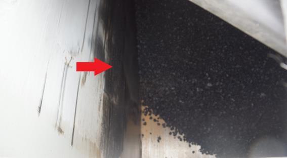
Prohibited, causes vehicle damage
Fig. 2: Model may vary. The illustration serves as an example.
Caution when reversing:
Because the area behind the trailer cannot be seen, or can only be partially seen from the operator workstation, a signaller is mandatory when reversing (as required by German road traffic regulations)
Modifications and changes
Any unauthorised modifications and changes to the vehicle (such as welding onto bearing parts) will void all liabilities and the manufacturer's warranty
Additions or modifications of any kind can affect the electromagnetic behaviour the vehicle. Therefore, do not make any changes or add anything to the vehicle without consulting and receiving written agreement from the manufacturer.
Replacement/wear parts and auxiliary materials
The use of replacement and wear parts or auxiliary materials from third parties can lead to dangers. The manufacturer accepts no liability for damage resulting from the use of these parts. Therefore, use only original parts or parts approved by the manufacturer.
Transport of certain media
Vehicles with push-off technology are not designed for chemically aggressive media.
If you use these vehicles to transport aggressive substances such as salt, bases, acids, fertilisers, sludge, ash and household waste, you do so at your own risk.
The exceptionally high level of stress can cause damage due to excessive corrosion, damage to the hydraulic and braking system as well as stress cracks.
The sale therefore excludes any warranty for the corrosion protection of all components and paintwork, stress cracks as well as the hydraulic system.
Ongoing INTENSIVE maintenance, cleaning and conservation of all components is strongly recommended.
2.3 Service life of the vehicle
• The service life of this vehicle greatly depends on its correct use and maintenance as well as the specific application and operating conditions.
• Following the instructions and information in these operating instructions will safeguard the operational readiness of the vehicle and maximise its service life.
• After each season of use, the vehicle must be checked thoroughly for signs of wear and other damage.
• Damaged or worn parts must be replaced before resuming operation.
• Following a prescribed, type-specific period of use, the vehicle must be subjected to a comprehensive technical inspection.
A decision as to the continued use of the vehicle must then be made based on the results of this inspection.
• The service life of the vehicle is theoretically unlimited since all worn or damaged parts can be replaced.
2.4 Dangers when working with the vehicle
Risks and impairments can arise when using the vehicle:
• Risk to life and limb of the operator or third parties
• Risks for the vehicle itself
• Risks for other material assets
Safe and fault-free operation of this vehicle requires knowledge of the safety and user instructions set out in this manual.
Always store the operating instructions at the usage location of the vehicle. The operating instructions must be available to operators and maintenance personnel at all times. Also be aware of the following:
• General and location-specific regulations regarding accident prevention and environmental protection.
2.4.1
Driving on public roads
When travelling on public roads, there is a risk of collisions with bridges, tunnels and other structures. This can result in personal injury and vehicle damage and could also cause significant damage to the transported goods and the relevant structure.
• Note the maximum vehicle dimensions incl. the dimensions of the transported goods.
• Note the permissible clearance dimensions (height, width).
2.4.2 Manoeuvring and coupling/uncoupling
When manoeuvring and coupling/uncoupling, there is a risk of potentially fatal crushing between the towing vehicle and the trailer for persons located in the working range of the vehicle.
• Only reverse with the towing vehicle if no persons are endangered by this manoeuvre.
• Always use a signaller when manoeuvring.
• Before coupling, secure the trailer with wheel chocks to prevent accidental movement.
• Instruct all persons to leave the area between the towing vehicle and trailer during the coupling operation.
2.4.3 Parking
Unintentional trailer movements, instability and poor visibility can cause serious accidents and injuries.
• Always apply the parking brake.
• Place wheel chocks under the wheels.
• When parking the vehicle in public traffic areas during hours of darkness, the vehicle must be labelled appropriately in accordance with national regulations.
2.4.4 Load securing
Incorrect load distribution or inadequately secured loads can result in dangerous vehicle behaviour along with serious accidents or damage to the vehicle. Other road users can be injured by falling loads.
• Loads must be secured in accordance with the applicable regulations.
• Equipment used to secure loads must be undamaged and fully functional.
• Observe the prescribed axle and drawbar loads.
2.5 Residual risks
The vehicle is built according to the state of the art and recognised safety rules. However, during use there is a risk to life and limb for the user or third parties, or risk of damage to the vehicle or other property.
In addition to the manufacturer's countermeasures against dangers caused by residual energy, the operator must also take appropriate countermeasures. Personnel must be briefed about these dangers and the measures to be taken to prevent them.
2.6 Obligations of the operating company
The operating company is required to instruct its personnel regarding:
• Basic regulations concerning work safety and accident prevention
• Correct handling of the vehicle
• The operating instructions (ensure that personnel have read and understood them)
The operator is obligated to:
• Keep all hazard symbols on the vehicle in legible condition
• Replace any damaged or removed hazard symbols
The requirements of the EC Directive for the use of work equipment 89/655/EEC must be observed.
2.7 Obligations of personnel
Before commencing work, all personnel who are tasked with working on the vehicle agree to:
• Comply with the basic regulations regarding work safety and accident prevention
• Read and comply with the safety section and warnings in these operating instructions
• Please contact the manufacturer with any questions; see page 80
2.8 Qualification of operating personnel
To avoid accidents, any person working with the vehicle must meet the following minimum requirements:
• He or she must be physically capable of controlling the vehicle.
• He or she can perform their work with the vehicle safely and in compliance with these operating instructions.
• He or she understands the function of the vehicle within the context of their duties and can recognise and avert the dangers arising from their work.
• He or she is familiar with the safe operation of vehicles.
• For travel on public roads, he or she possesses sufficient knowledge of road traffic regulations as well as the required driver's license.
2.9 Qualification of specialist personnel
If the required work on the vehicle (assembly, alteration, conversion, extension, repairs, retrofits) is performed incorrectly, this can lead to serious injuries or death. To avoid accidents, any person performing work in accordance with these operating instructions must meet the following minimum requirements:
• He or she is a qualified specialist with the requisite training.
• Based on their technical expertise, he or she is able to assemble the (partially) disassembled vehicle as described in the manufacturer's assembly instructions.
• Based on their technical expertise, he or she is able to extend, alter or restore the function of the vehicle as prescribed in the relevant instructions of the manufacturer.
• He or she can perform the work described in these instructions in a safe manner.
• He or she understands the function of the required work as well as the vehicle and can recognise and avert the dangers arising from this work.
• He or she has read these operating instructions and can apply the information contained therein in an appropriate manner.
Maintenance and repair work indicated by this symbol must be performed only by a specialist workshop. The personnel of the specialist workshop must have the requisite knowledge and appropriate equipment (tools, lifting and supporting devices) to maintain and/or repair the vehicle in a safe and professional manner.
2.10 Personal protective equipment
To ensure operator safety, the operating company must:
• Provide safety footwear with protective toe caps.
• Define and provide personal protective equipment for the relevant application.
• Ensure that all personal protective equipment is in flawless condition and offers effective protection.
• Observe the national regulations regarding personal protective equipment.
• Use the correct safety and protective devices, as per regulations.
Operation is permitted only if all safety and protective devices are complete and fully functional.
2.11 Operational safety
Operational safety is given in the case of fault-free, safe operation of a device or vehicle. The device or vehicle must function without fault throughout the period of use and must pose no risk to the operator when used as intended and for its designated purpose.
2.11.1 Operation without correct start-up
Without a correct start-up in accordance with these operating instructions (section 4), the operational safety of the vehicle is not guaranteed. This can result in accidents involving personal injury.
2.11.2 Safeguarding perfect technical condition
Incorrect maintenance and adjustments can impair the operational safety of the vehicle and lead to accidents involving personal injury.
• All maintenance and adjustment work must be performed as described in the relevant section.
• Shut down and secure the vehicle before performing any maintenance and adjustment work.
2.11.3 Danger due to vehicle damage
Damage to the vehicle can impair its operational safety and lead to accidents involving personal injury. The following vehicle components are particularly safety-relevant:
• Brakes
• Safety devices
• Coupling mechanisms
• Lighting
• Hydraulics
• Tyres
In the case of doubts regarding the operational safety of the vehicle, e.g. due to leaking fluids, visible damage or unexpected changes in driving behaviour:
• Shut down and secure the vehicle.
• Eliminate potential causes of damage immediately, e.g. remove dirt and debris or tighten loose screws.
• Establish the cause of the damage as per these operating instructions.
• Repair the damage as per these operating instructions.
• In the case of damage that cannot be rectified independently as per these operating instructions:
o Have the damage repaired by a qualified workshop.
2.11.4 Technical limits
If the technical limits of the vehicle are not maintained, this can cause damage to the vehicle. This can result in accidents involving personal injury.
Compliance with the following technical limits is particularly important from a safety perspective:
• Maximum permissible operating pressure of the hydraulic system
• Maximum permissible speed
• Permissible application and age of the tyres
• Maximum permissible axle load(s)
• Maximum permissible payloads
• Maximum permissible drawbar load
2.12 Safety and protective devices
The vehicle is equipped with the following safety and protective devices:
2.12.1 Emergency stop device
The towing vehicle (semi-trailer tractor) is used to shut down the machine in the event of an emergency. When the drive motor of the towing vehicle is turned off, all drives and the power supply of the trailer are switched off immediately.
2.12.2 Description of additional safety and protective devices
The following safety devices are installed on the vehicle:
• Service brake system
• Parking brake (PB)
• Wheel chocks (x2)
• Hydraulic shut-off valve
2.12.3 Faulty protective devices
Defective safety equipment can lead to dangerous situations. Therefore:
- Switch off the vehicle immediately.
- Protect it against being turned on again.
- If necessary, disconnect the hydraulic, compressed air and electrical supply.
2.12.4 Inspecting safety and protective devices
All safety and protective devices must be checked regularly prior to start-up. Inspection intervals according to table:
Safety device
Tightness of the hydraulic system; functional check of the lighting
General condition of the vehicle
Brake system with parking brake
2.13 Workstation of operating personnel
The vehicle is designed to be used by one person only. The main workstations are:
Inspection interval
Visual inspection before each use
Weekly
Before (during) every start-up
The driver's seat of the towing vehicle (semi-trailer tractor)
Fig. 3: Workstation on the vehicle
2.14 Danger zones
Within the danger zone of the vehicle, danger points exist that pose either a permanent hazard or are a potential source of unexpected risks. These danger points are indicated by warning symbols, which highlight residual risks that cannot be eliminated by design.
The specific safety guidelines of the relevant sections apply in this case.
A danger zone exists around the vehicle when in use. To ensure that no persons enter this danger zone, the minimum safety distance must be observed. If this safety distance is not adhered to, this can result in accidents involving personal injury.
• Only switch on the vehicle if there are no persons within the danger zone.
• Cease operation immediately if persons enter the danger zone.
The minimum safety distances are as follows:
The values specified above are minimum safety distances based on designated use of the machine. These values depend on the individual application and environmental conditions and must be increased where necessary. The vehicle must be shut down and secured for all work performed within the danger zone, including brief checks.
Other relevant specifications in all applicable operating instructions must be observed:
• The operating instructions of the towing vehicle
• The operating instructions of the vehicle
• The operating instructions of the attachments/accessories
Fig. 4: Danger zone
2.14.1 Safety distance from overhead lines
RISK OF DEATH! Always adhere to the safety distances!
Overhead lines carrying voltage Safety distances from overhead lines
Up to 1 kV 1 m on all sides
> 1 kV – 110 kV 3 m on all sides
> 110 kV – 220 kV
> 220 kV – 380 kV
2.15 Vehicle labelling
m on all sides
m on all sides Unknown voltage
Observe all warnings and safety instructions on the vehicle as well as other labelling such as turning and transport directions.
The type plate is applied to the vehicle for identification purposes.
Type plate to specifically identify the vehicle.
(See section 10.3)
CE marking
Certifies conformity with applicable EU directives that relate to the product and require a CE marking. (On type plate)
• Warning stickers are applied to the vehicle to warn of the following residual dangers, which cannot be eliminated by design.
• The information stickers draw attention to vehicle-specific information that must be observed to ensure correct function of the vehicle.
o The stickers must be kept clean and must be clearly visible at all times.
o Damaged or missing stickers must be replaced.
o When attaching additional devices, the corresponding warning and/or information stickers must be added where required. Consult with the manufacturer where necessary.
Safety instructions
Sticker Description
Information in operating instructions: Read contents of operating instructions before handling.
Final inspection: information sign for completed final inspection of vehicle
Attention!
Risk of hand injuries. Danger when reaching into openings.
Information sign for bolt and wheel nut check
Speed sign:
Design-based maximum speed for the trailer
Parking brake
Warning against crushing or entanglement
Lubrication point
Operation of the parking brake (dependent on brake manufacturer)
Raising/lowering valve
Fig. 5: Warnings and safety instructions affixed to the vehicle
3.Vehicle description
This section provides a comprehensive overview of the layout and function of the vehicle. You should ideally read it at the vehicle. This is the best way for you to familiarise yourself with the vehicle.
3.1 Applications
Depending on the vehicle type, the push-off semi-trailer can be used to transport viscous and sticky materials (loam, wet ground, clay, etc.) – even in winter.
In addition, very sticky asphalt types (OPA, PMA, stone mastic, rubber-modified, etc.) can also be transported – again depending on the vehicle type. The push-off technology allows these materials to be unloaded without leaving any residue. With the push-off technology, it is possible to unload "piece-by-piece", with mechanical and thermal mixing. A particular risk that you can mitigate with the push-off technology is the danger zones that exist near power lines, on avenues or under bridges when unloading.
3.2 Design variants – standard
Designation
3.3 Functional description
Loading the trailer
Loading is performed as follows:
From above into the trailer body by means of external equipment (excavator, loader, etc.)
• The rear panel must be closed.
• The sliding floor unit must be in front end position.
Unloading the trailer
At the unloading point:
- Perform the unloading process from the operator workstation.
- Open the rear panel.
- Extend the sliding floor with the bulkhead to the rear end position.
- Move the sliding unit to the front end position.
- Close the rear panel and check it is locked securely.
Ensure that the rear panel is opened before you begin the push-off process. Otherwise the rear panel may be damaged. Retract the sliding unit before closing the rear panel.
3.4 Layout of the vehicle
The following figure provides an overview of the most important components and assemblies and shows where they are installed on the vehicle:
Fig. 6: Layout and components
3.5 Assemblies and components
The different variations of these components are described under "Equipment" (sections 8 and 9)
Item 1 – draw gear
The 2" kingpin is used to connect the trailer to the fifth-wheel plate of the towing vehicle.
Item 2 – compressed air connections/lines
The compressed air connections are used to connect the service brake of the trailer to the brake system of the towing vehicle.
Item 3 – hydraulic connectors/lines
Individual hydraulic connections are provided for all hydraulic functions.
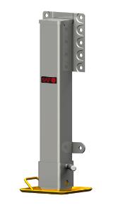
Item 4 – supporting mechanism
The support winches are used to park and raise the trailer.
Standard: Two mechanical supporting feet are fitted.
Option: Mechanical (geared) support winches can be installed.
(See section 4.3)
– item 2
– item 3
Fig. 7: Assembly – item 1
Fig. 8: Assembly
Fig. 9: Assembly
Fig. 10: Assembly – item 4
Vehicle description
Item 5 – parking brake
The parking brake system is an auxiliary function that switches the spring-type cylinders to brake position in the case of uncoupling or pressure loss.
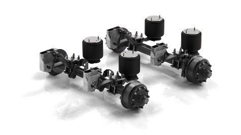
Item 6 – axle assembly
Multiple axle assembly versions are available for the ASS.
(See section 12.1)
Item 7 – body
The bridge is self-supporting and thus forms the main frame of the vehicle.
Item 8 – sliding floor cylinder
A separate sliding floor cylinder exists for each vehicle type; its size and installation length depends on the vehicle length.
Item 9 – moving panel and sliding floor
Depending on the truck type, different moving panel units are used to empty the load.
Item 10 – hydraulic rear panel
The loaded goods are unloaded via the hydraulic rear panel. The rear panel consists of two parts.
Item 11 – temperature display
The temperature display indicates the temperature inside the ASS.
5
6
8
9
Fig. 11: Assembly – item
Fig. 12: Assembly – item
Fig. 13: Assembly – item 7
Fig. 14: Assembly – item
Fig. 15: Assembly – item
Fig. 16: Assembly – item 10
Fig. 17: Assembly – item 11
3.6 Notes regarding equipment versions
• High level of stability, even on inclines.
• Quick and safe unloading under bridges and power lines, in alleys and industrial buildings, etc.
• Very low load centre of gravity ensures significantly faster and better handling on country roads and off-road.
• Enhanced transport performance with reduced wear and diesel costs.
o Less hard braking of vehicle before corners thanks to "lowered vehicle".
o Less hard acceleration after corners reduces diesel consumption.
• Extremely low loading height
o Easier loading with better overview even when using small wheel loaders and excavators.
• Complete emptying, even with highly viscous materials such as clay, loam, silt, "silent asphalt".
o No manual cleaning or scraping of the tipper bridge required.
o Enhanced safety due to lower risk.
• Complete emptying of body even with asphalt types such as stone mastic, OPA, PMA, rubber-modified bitumen.
o Reduces standing times and costly disposal of purchased mixture.
• Enhanced paving quality due to continuous mixing throughout the unloading process.
3.6.1 Asphalt Thermo ASS 372 Mega
• Total trailer weight 40,000 kg acc. to EU standardisation
Axle load 3 x 9,000 kg with 1,310 mm axle spacing
Assumed coupling load technically up to 13,000 kg
Note: The specified total weight is technically possible but, depending on the loaded material, may not be achievable when adhering to the permitted axle and coupling loads.
3.6.2
ASS 272 two-axle
• Total weight 33,000 kg, rear axle load (technically up to 18,000 kg) with 1,310 mm axle spacing, assumed coupling load (technically up to 15,000 kg)
• Total weight 35,000 kg, rear axle load (technically up to 18,000 kg) with 1,310 mm axle spacing, assumed coupling load (technically up to 17,000 kg)
• Total weight 35,000 kg, rear axle load (technically up to 20,000 kg), assumed coupling load (technically up to 15,000 kg)
Axle load 2 x 10,000 kg with 1,310 mm axle spacing (export only)
Note: The specified total weight is technically possible but, depending on the loaded material, may not be achievable when adhering to the permitted axle and coupling loads.
3.6.3 ASS 272 Compact
• Total weight 33,000 kg, rear axle load (technically up to 20,000 kg), assumed coupling load (technically up to 13,000 kg)
Axle spacing 1,810 mm
Note: The specified total weight is technically possible but, depending on the loaded material, may not be achievable when adhering to the permitted axle and coupling loads.
Vehicle description
3.6.4 ASS 372 three-axle and ASS 382 three-axle
• Total trailer weight 40,000 kg acc. to EU standardisation
Axle load 3 x 9,000 kg with 1,310 mm axle spacing
Assumed coupling load technically up to 13,000 kg
• Total trailer weight 42,000 kg acc. to EU standardisation
Axle load 3 x 9,000 kg with 1,310 mm axle spacing
Assumed coupling load technically up to 15,000 kg
• Total trailer weight 42,000 kg acc. to EU standardisation
Axle load 3 x 9,000 kg with 1,310 mm axle spacing
Assumed coupling load technically up to 17,000 kg
Note: The specified total weight is technically possible but, depending on the loaded material, may not be achievable when adhering to the permitted axle and coupling loads.
In the case of materials that are difficult to move or that are highly adherent, the permissible load volume may be reduced by up to 10 percent
3.6.5 ASS 377 extra long
• Body with projection and hydraulic axle adjustment
Vehicle configuration for Sweden, Norway, Finland
• Attention: Distance from kingpin to centre of last axle: approx. 9610 mm
• Permitted total weight for Norway, Sweden, Finland up to 50,000 kg
Note: The specified total weight is technically possible but, depending on the loaded material, may not be achievable when adhering to the permitted axle and coupling loads.
In the case of materials that are difficult to move or that are highly adherent, the permissible load volume may be reduced by up to 10 percent
Fig. 18: Type ASS extra long
3.6.6 ASS 382 extra long – telescopic
• Body with projection – type Scandinavia / UK / Ireland.
Attention: Distance from kingpin to centre of last axle: approx. 8010 mm
• Semi-trailer total weight 40,000 kg acc. to EU
Gross train weight technically up to 44,000 kg
Assumed coupling load technically up to 13,000 kg
• Semi-trailer total weight 42,000 kg acc. to EU
Gross train weight technically up to 44,000 kg
Assumed coupling load technically up to 15,000 kg
Note: The specified total weight is technically possible but, depending on the loaded material, may not be achievable when adhering to the permitted axle and coupling loads.
In the case of materials that are difficult to move or that are highly adherent, the permissible load volume may be reduced by up to 10 percent
Fig. 19: Type ASS extra long – telescopic
3.7 Technical data
Type:
* Optional
All dimensions are in mm and may deviate depending on the version. The specified dimensions are based on the standard tyres.
In the case of materials that are difficult to move or that are highly adherent, the permissible load volume may be reduced by up to 10 percent
Coupling load (approx. kg)
Type
ASS 272
ASS 372
ASS 377
ASS 382
Version
Two-axle x
Two-axle "Compact" x
Three-axle
Three-axle "Asphaltprofi Thermo … Mega"
Three-axle "extra long – telescopic"
Three-axle
Three-axle "extra long"
1) Acc. to EU standardisation 2) Perm. total weight in SWE / FIN / NOR
All trailers are in basic condition.
The weight specifications comply with German Road Traffic Licensing Regulations (StVZO).
It is possible that different vehicle class provisions exist in different countries.
The mass figures are version-specific and may differ.
Details are provided on the type plate, for example.
The weights and drawbar loads were partially determined by calculation and may differ in practical applications.
The centre of gravity and thus the drawbar load may shift depending on how the load is distributed.
If auxiliary devices are used, the payloads, empty loads and axle loads will change.
The stated total weight is technically possible but, depending on the loaded material, may not be achievable when adhering to the permitted axle and coupling loads.
The load volume may be slightly reduced when using a tarpaulin.
4.First-time start-up
• Without a correct first-time start-up in accordance with these operating instructions, the operational safety of the trailer is not guaranteed. This can lead to accidents resulting in serious injury or death.
• All setting and adjusting tasks must be performed for first-time start-up.
• Before starting work, the operator must familiarise himself with all actuating devices and their function.
• It is too late to do so once work has started.
• Verify the operational and transport safety of the trailer before first-time start-up.
• The trailer must only be coupled and transported with a towing vehicle that is suitable for this purpose.
• The towing vehicle and trailer must comply with the national road traffic regulations
• The vehicle owner (operating company) and the vehicle driver (operating personnel) are responsible for observing the legal provisions of national road traffic regulations.
• Observe the safety instructions that are affixed to the trailer. An explanation of the individual warning symbols is provided on page 29 of these operating instructions.
• Also comply with the instructions in the relevant sections and in the appendix of these operating instructions.
• Before first-time start-up, instruct persons to leave the danger area, e.g. around hydraulic equipment and drives.
• There is a risk due to crushing and shearing points in the following areas: complete danger zone (see section 2.14), moving equipment (e.g. moving panel unit, rear panel) and draw gear.
4.1 Setting up the trailer coupling on the towing vehicle
Move the towing device of the towing vehicle to the correct position.
On the towing vehicle, the fifth-wheel plate can be adjusted hydraulically in longitudinal direction. This adjustment is made to control the behaviour of the trailer on the road or field.
20: Setting up the trailer coupling on the towing vehicle
For instructions on setting up the fifth-wheel plate, refer to the operating instructions of the towing vehicle.
Fig.
4.2 Draw gear
Important when switching towing vehicles: When changing the towing vehicle, ensure that it possesses the necessary support and towing capabilities.
4.2.1 Kingpin
Important when switching towing vehicles: When changing the towing vehicle, ensure that it possesses the necessary support and towing capabilities.
The towing vehicle must feature a suitable fifth-wheel plate for connecting the kingpin.
The permissible coupling load transmitted by the semi-trailer must be observed.
The kingpin is part of the coupling mechanism between the semi-trailer and towing vehicle. 2" kingpin on semi-trailer frame
Procedure
Check the following before coupling:
Fifth-wheel plate on towing vehicle for coupling the semi-trailer
- Is the vertical load of the towing vehicle sufficient for the trailer?
- Are the fifth-wheel coupling and kingpin compatible?
- Do the coupling heights of the towing vehicle and trailer match?
- Is the trailer loaded correctly?
- Is the fifth-wheel plate sufficiently lubricated?
4.3 Setting the coupling height
Objective
Setting the trailer height for coupling.
The trailer (type-specific) is designed for a coupling height of approx. 1220 mm or 1270 mm (optional 1,350 mm). The exact coupling height can be set by adjusting the supports.
Fig. 21: Kingpin
Fig. 22: Fifth-wheel plate
5.Start-up
5.1 Basic prerequisites
The following modes of transport are needed to transport the trailer: Towing vehicle (e.g. semi-trailer tractor) with fifth-wheel plate and suitable brake, hydraulic and lighting connections.
The supply connections are located at the front in the hose tray. This includes:
- Connections for the power supply
- Compressed air connections
- Hydraulic connections
• The trailer must be fully and correctly coupled.
• The permitted maximum speed must not be exceeded.
• It is not permitted to transport persons on the trailer.
• The roadworthiness of the trailer – particularly the lighting, tyres, closed openings etc. – must be checked before travelling on public roads.
• Before moving off, ensure that perfect visibility exists on and around the towing vehicle and of the trailer itself.
Before travelling on public roads, ensure that:
- The trailer is fully and correctly coupled to a suitable towing vehicle.
- All safety devices are locked and secured.
- The tyres are free of cuts and cracks and have the correct tyre pressure.
- The trailer is free of dirt and debris.
- The lighting system functions flawlessly.
- The brake system functions flawlessly.
- The cables and lines are routed such that they do not stretch or come into contact the wheels of the towing vehicle when cornering
5.2 Check before start-up
The points below will facilitate trailer start-up. For more detailed information, refer to the relevant sections in the operating instructions. Check to ensure that all safety devices (covers, panels, etc.) are in proper condition and are attached to the trailer in protective position.
- Lubricate the trailer according to the lubrication schedule.
- Check that all screw connections are leak-tight and secure.
- Check the tyres to ensure the air pressure is correct. (See section 10.4.6)
- Check the tightness of the wheel nuts.
- Check the oil level of the hydraulic system and inspect it for leaks.
- Connect all connecting lines (e.g. hydraulics, compressed air etc.) correctly and secure them.
- Test the brake system. (See section 7.1.6)
- Check the cargo space for loose parts lying inside.
- Check the correct function of the fifth-wheel plate.
- Check the condition of the sealing strips on the moving panel. (See section 10.6)
5.3 Returning to service
After an extended storage period, the same steps as for first time start-up must be completed.
See section 4
5.4
Coupling/uncoupling trailers
Important when switching towing vehicles: When changing the towing vehicle, ensure that it possesses the necessary support and towing capabilities
Note the permitted maximum speeds and axle loads with regard to the operational limits of the coupling mechanism. These are specified on the type plate.
There is a risk of crushing between the towing vehicle and the trailer during coupling/uncoupling. Therefore, all persons must be instructed to leave the danger area. When using a signaller, this person must stand at a sufficient safety distance from the vehicle combination.
Coupling procedure
- Check that the coupling mechanism on the towing vehicle is fully functional and secure.
- Verify that the trailer coupling mechanism of the towing vehicle is compatible with the trailer's draw gear.
- Reverse the towing vehicle slowly up to the trailer, leaving a gap of approx. 0.5 m.
- Check that the coupling points are at the same height. Adjust the height if necessary.
- In the next step, drive the towing vehicle towards the trailer to establish the coupling. Then check that the coupling mechanism has engaged correctly.
- Retract the supporting mechanism.
- You can then release the parking brake and remove the wheel chocks.
- Connect the supply lines to the towing vehicle.
Uncoupling procedure
- Park the vehicle combination in a line.
- Apply the parking brake. Place the wheel chocks under the wheels for safety.
- Extend the supporting mechanism.
- Disconnect the supply lines from the towing vehicle.
- Open the coupling mechanism.
- Drive the towing vehicle away from the vehicle slowly and in a straight line.
5.5 Supply and control connections
Driving without connected supply and control connections between the towing vehicle and trailer will impair the driving and braking behaviour of the vehicle combination and is prohibited by law. An increased risk of accidents exists due to the absent functionality.
Damaged or insufficient supply and control connections between the towing vehicle and trailer will impair the driving and braking behaviour of the vehicle combination and can lead to accidents.
A number of connections are provided at the front of the trailer to enable control of the vehicle functions and braking as well as to supply power and air to the trailer.
5.5.1
Electrical supply
All wiring and connections on the trailer are fully fitted and ready to use. Do not tap in directly to the ignition switch. (Risk of fire or damage to the electrical system)
If your towing vehicle does not feature a plug connection, it must be fitted.
This preparation must only be carried out by a specialist workshop. Use only original fuses. If fuses with an excessively high rating are used, the electrical system will be destroyed. When electrical devices and/or components are installed on the vehicle at a later stage, and connected to the on-board power supply, it is the user's responsibility to verify whether this installation results in faults or malfunctions of the vehicle electronics or other components.
When establishing the connections, ensure that the plugs and sockets are clean and dry. Contamination and moisture can lead to short-circuits.
Ensure that any electrical and electronic components installed at a later stage comply with the EMC Directive 2014/30/EU, as amended over time, and bear the CE mark.
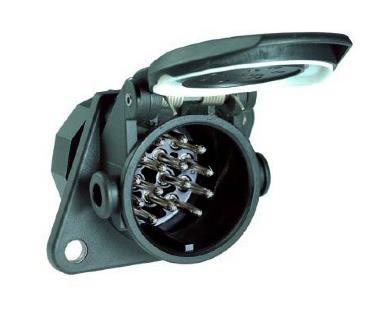
If a reversing camera is fitted, the corresponding socket has a red marking to avoid confusion with the other 7-pin socket.
If no remote control is available to control the trailer, this socket is required for operation via the Fliegl control box.
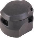
1. ABS/EBS 24 V socket for brake system, 5/7-pin ISO 7638-1
2. 2x 7-pin socket ISO 3731 S-type
o 1x lighting
o 1x additional equipment (see point 3)
3. 15-pin socket 24 V ISO 12098
o Lighting
o Hydraulic control
o Paver brake
o Rear light
o Lift axle
4. 7-pin socket ISO 1185
o Reversing camera
5. NATO socket for sliding tarpaulin power supply
6. 7-pin socket ISO 1724 / type 12N
Fig. 23: Electrical connections
5.5.2
Compressed air supply
Connection procedure:
Connect the coupling head of the brake line YELLOW) to the yellow port on the towing vehicle as prescribed.
Connect the coupling head of the supply line RED) to the red port on the towing vehicle as prescribed.
When you connect the supply line (red), the supply pressure from the towing vehicle automatically pushes out the actuating button for the release valve on the trailer brake valve.
• When coupling the brake and supply line, ensure that:
o The sealing rings on the coupling heads are clean.
o The sealing rings on the coupling heads form a tight seal.
• Replace any damaged sealing rings immediately.
• Drain the air reservoir before your first journey of the day.
• Do not set off with the coupled trailer until the pressure gauge on the towing vehicle shows a pressure of 5.0 bar.
Disconnection procedure:
Secure the trailer to prevent it rolling away. You can do this using the parking brake and/or wheel chocks.
Undo the coupling head of the supply line RED).
Undo the coupling head of the brake line YELLOW) as prescribed.
The service brake of the trailer only engages when the red coupling head has been removed. You must follow the above sequence as, otherwise, the service brake system will disengage, which in turn can set the unbraked trailer in motion.
When coupling or uncoupling the trailer, the supply line to the trailer brake valve is vented. The trailer brake valve switches over automatically and actuates the service brake system on the basis of the ALB brake force regulation.
Fig. 24: Standard couplings ISO 1728
Fig. 25: Standard couplings ISO 1728
5.5.3 Hydraulic supply
A hydraulic oil supply and control by the towing vehicle are required for all work functions.
Procedure:
Clean the hydraulic connections if necessary. Set the lever on the control device to neutral position. Ensure that the screw couplings are clean.
Connect the pressure line to the single-action control device.
Connect the oil return hose to the oil return line (T) of the towing vehicle.
When connecting hydraulic hoses to the towing vehicle hydraulics, make sure that the hydraulics are depressurised on both the towing vehicle and trailer side.
Single-action control units required: The return must not be valve-controlled.
5.5.4 Towing vehicle parameters (hydraulics)
Hydraulic parameters
• Pressure inlet (P) with HDK screw connector 18L - NW20/6 (M48 x 3) (size 6)
• Return (T) with HDK screw connector 22LNW 20/6 (M48 x 3) (size 6)
• Oil pressure from truck to hydraulic system: approx. 200 bar.
• The oil pressure is set to approx. 180 bar at the control cabinet.
Maximum working pressure = 180 bar!
• Required oil volume: 100 l/min - max. 120 l/min
• Recommendation for active hydraulic system (during push-off process): raise speed on towing vehicle to approx. 850 rpm
If these components are not compatible with the connections on the towing vehicle, the customer must supply suitable screw couplings or adapters.
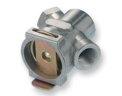
Fig. 26: Hydraulic connections
Fig. 27: Hydraulic connector
• The dimensions of hydraulic couplings can vary slightly between different manufactures, as a result of which the connection may not form a tight seal.
• Common causes of faults:
o One of the screw couplings is not fully tightened ➔ return blocked/reduced
o Return filter on semi-trailer tractor closed ➔ back pressure builds up
o Working/operating pressure on towing vehicle not set correctly, e.g. 150 bar instead of 200 bar
General safety instructions for the hydraulic system
1. The hydraulic system is under high pressure.
2. Observe the maximum permissible operating pressure of 180 bar!
3. Dirty hydraulic couplings must be cleaned prior to connection.
4. Ensure that the plug and socket are connected correctly and securely.
5. When connecting hydraulic hoses to the towing vehicle hydraulics, ensure that the hydraulics are depressurised on both the towing vehicle and trailer side. If the connections are swapped, the functionality will be reversed – risk of accidents!
6. Coupled hydraulic hose lines:
o Must easily withstand all movements during cornering without excess tension, bending or friction
o Must not rub against other parts
7. Check hydraulic hoses and couplings regularly and replace them if they are damaged or old (at least every 6 years).
8. The replacement hoses must meet the requirements of the device manufacturer.
9. When locating leaks, use suitable aids to prevent injury.
10. Never try to close leaks with your finger.
11. Liquids (hydraulic oil) escaping under high pressure can penetrate the skin and cause serious injuries.
12. In the event of injuries, seek medical assistance immediately – risk of infection!
13. Before working on the hydraulic system, depressurise it and switch off the tractor engine.
14. Only specialist workshops are permitted to perform repair work on the hydraulic system.
15. Ensure that the oil is of the required grade.
16. Caution when draining hot oil – risk of burns!
17. When coupling and uncoupling, make sure that no dirt enters the couplings of the hydraulic hoses.
6.Preparation and setup
The following steps must be performed to set up and prepare the vehicle:
• Setting the coupling height
• Establish the supply connections
Important when switching towing vehicles: When changing the towing vehicle, ensure that it possesses the necessary support and towing capabilities.
6.1 Air suspension– raising and lowering [option]
When the speed exceeds 15 km/h (manufacturer specification), the lever automatically moves from "Stop" to "Drive" position. There must be no persons in the danger area during raising and lowering.
Lever position of the air suspension system
Stop
➔ Position the lever VERTICALLY and push it in.
Raise/lower
➔ Move the lever to the RIGHT to raise
➔ Move the lever to the LEFT to lower
(The lever must be pressed in to do this.)
Travel
➔ Position the lever VERTICALLY and pull it out Ⓕ
The positions
• Raise
• Lower must not be used for general applications.
Exceptions:
• Brief manoeuvring operations
• Cleaning work
• Parking the trailer
Position "Ⓕ" (floating position) is the correct travel and working position for the trailer. This position is suitable for general applications.
Fig. 28: Raising and lowering with air suspension
Fig. 29: Air suspension height
6.2 Compressed air brake system with ALB, brake force regulator
When the speed exceeds 15 km/h (manufacturer specification), the lever automatically moves from "Stop" to "Drive" position. There must be no persons in the danger area during raising and lowering.
Check the braking effect of the compressed air brake system before setting off.
For every use (driving operation), the brake force must be set according to the trailer load. Prerequisite for operation: Compressed air brake connection (dual line brake system) on towing vehicle
Selecting the operating mode, adjusting the trailer load status
"Release" operating mode for moving the uncoupled trailer is triggered via the trailer release valve.
The button must be pushed in for this purpose.
You must not alter the setting dimension of the automatic load-dependent brake force regulator. The setting dimension must match the value specified on the ALB plate.
Fig. 30: Manual brake force adjustment
Trailer release valve button
6.3
Brake system with combined service/parking brake (Tristop)
The parking brake system is an auxiliary function that switches the spring-type cylinders to brake position in the case of uncoupling or pressure loss. Before travel, the spring-type cylinders must be manually released via the park valve (red button).
Parking brake operation
Pulling the park valve (red button) connects the spring-loaded brake system to the vent. This depressurises the spring-loaded brake system and actuates the parking brake.
Pushing the park valve (red button) connects the spring-loaded brake system to the reservoir, which builds up the pressure in the spring-loaded brake system, resulting in the parking brake being released.
The spring-loaded brake system must always be released manually following an uncoupling operation.
However, a release can only take place when the pressure in the reservoir is at least 5 bar.
Manoeuvring
To manoeuvre the uncoupled vehicle, both buttons must be pressed – first black and then red Only then is the parking brake released and the vehicle unbraked.
After manoeuvring, the park valve (red button) must be pulled out again (min. 5 bar supply pressure) to re-apply the parking brake.
Pressureless system
Release valve (black button) must be pressed (secure trailer vehicle); park valve (red button) is pushed out automatically.
Initial filling
Apply pressure from towing vehicle; release valve (black button) must move to operating position (springs out). Park valve (red button) remains pushed out.
Fig. 31: Tristop control unit
Fig. 32: Parking brake
Automatic emergency braking
Push in the red button. Reduce the pressure to 0 bar (disconnect towing vehicle supply); the red button must spring out and emergency braking must be initiated.
Parking brake valve
Apply pressure from the towing vehicle. Push in the park valve (red button); at least 5 bar in reservoir; pull out the park valve (red button); parking brake must be depressurised (to 0 bar); vehicle is braked.
There must be no persons in the danger zone during coupling and uncoupling.
This section provides brief instructions on using the compressed air brake system.
Comprehensive information is available from the brake manufacturer www.haldex.com
Fig. 33: Parking brake
6.4 Electronic brake system (EBS)
EBS is an electronic brake system with load-dependent brake force regulation and automatic anti-lock system.
Trailer vehicles with such brake systems can only be used with:
• Towing vehicles with enhanced ISO 7638-1996 plug connection (7-pin, 24 V, towing vehicles with CAN data line)
Towing vehicles with ISO 7638-1985 plug connection (5-pin, 24 V, towing vehicles without CAN data line)
The trailer EBS consists of a park release safety valve, the EBS trailer modulator, an electro-pneumatic controller with integrated electronic control unit, integrated pressure sensors and integrated redundancy valves as well as the wiring and pipework for the components.
1) Park release safety valve
2) EBS trailer modulator
3) Speed sensors
4) Control unit
6.4.1 EBS modulator
The trailer modulator is used to control and monitor the electro-pneumatic brake system. It regulates the brake cylinder pressure on both sides of two or three axles. The trailer modulator is installed in the electropneumatic brake system between the reservoir or EBS trailer brake valve / park release safety valve and the brake cylinder near the axles on the vehicle frame.
34: EBS modulator
Fig.
6.4.2 Park release safety valve
The park release safety valve performs the emergency brake function if the pneumatic supply line should become detached and is also responsible for the function of the double release valve.
Using the release button of the service brake system (black), the brake system can be manually released without a compressed air supply after automatic braking, provided that there is sufficient supply pressure in the reservoir.
Using the actuating button (red), the parking brake can be applied or released by venting the spring accumulators.
When the vehicle is uncoupled (supply line vented), automatic braking is performed via the service brake with simultaneous bypassing of the check valve integrated in the park release safety valve within the spring brake circuit.
In the case of a drop in the supply pressure of the parked trailer, the spring accumulators automatically apply the braking force, thereby preventing the vehicle from rolling away.
All control functions remain active if the supply line should become detached.
6.4.3
Trailer brake valve
Version 1: The conventional trailer brake valve is used in conjunction with an external target pressure sensor.
Version 2: The conventional trailer brake valve is used without an external target pressure sensor since it is integrated in the modulator.
It is essential that a trailer brake valve without a supply line is used.
6.4.4 EBS relay valve
The EBS relay valve is used as an actuator for controlling the brake forces on the third axle for semi-trailers.
The electrical actuation and monitoring is performed by the modulator.
Fig. 35: Park release safety valve
Fig. 36: Trailer brake valve
Fig. 37: EBS relay valve
Preparation and setup
6.4.5 ABS relay valve
The ABS relay valve familiar from conventional brake systems and a double check valve are used in the electro-pneumatic brake system as actuators for controlling the brake forces on a steering axle for semi-trailers.
The electrical actuation and monitoring is performed by the trailer modulator.
6.4.6 Lift axle valve
With the two-circuit lift axle valve, up to two lift axles can be controlled automatically by the EBS depending on the current axle load.
The electrical actuation and monitoring is performed by the trailer modulator.
With the single-circuit lift axle valve, one lift axle can be controlled automatically by the EBS depending on the current axle load.
The electrical actuation and monitoring is performed by the trailer modulator.
After unscrewing the vent, an approach aid with residual pressure control is possible. For this purpose, a line is rerouted from the vent to the 3/2-way solenoid valve for the residual pressure control.
6.4.7 Double shut-off valve (select low valve)
In vehicles with 2S/"M+ select low control, the double shut-off valve is used to brake a single axle (e.g. steering axle). The input pressures are the pressures applied by the trailer modulator on either side. The lower pressure is then routed to the axle that is to be braked.
Fig. 38: ABS relay valve
Fig. 39: Lift axle valve
Fig. 40: Double shut-off valve
6.5 Hydraulic system
Procedure:
Connect the pressure line to the singleaction control device.
Connect the oil return hose to the oil return line (T) of the towing vehicle.
Double-action control unit
Connect the pressure line . (The pressure line leads to the pressure filter on the vehicle.) Connect the oil return hose to the oil return line (T) of the towing vehicle, as in the case of the single-action control device.
6.5.1 Hydraulic control unit
The hydraulic control unit consists of the control valves, which are actuated electrically, and a pressure gauge indicating the pressure in the hydraulic system. The push-off and rear panel functions are operated via this control unit.
Fig. 41: Hydraulic connection
Fig. 42: Hydraulic control unit
Preparation and setup
6.5.2 Control valve – check valve
The check valve prevents the "push-off" function starting before the "rear panel" function.
Otherwise the loaded material would be pressed against the rear panel.
6.5.3 Control valve – rear panel
The "rear panel" control valve is used to operate the movement of the rear panel.
1. Open rear panel
2. Close rear panel
6.5.4 Control valve – gate valve
The gate valve is used to operate the movement of the push-off unit.
1. Gate valve supply
2. Gate valve return
6.5.5 Emergency manual control
In the case of a power failure or a malfunction, the manual control feature can be used to depressurise the system and return the actuators to a safe state.
Procedure:
To use the manual control function, press a pin into the opening.
The manual control can be used as long as the pressure in connection T is less than 25 bar
• The dimensions of hydraulic couplings can vary slightly between different manufactures, as a result of which the connection may not form a tight seal.
• Common causes of faults:
o One of the screw couplings is not fully tightened ➔ return blocked/reduced
o Return filter on semi-trailer tractor closed ➔ back pressure builds up
o Working/operating pressure on towing vehicle not set correctly, e.g. 150 bar instead of 200 bar
Fig. 43: Check valve
Fig. 44: Rear panel control valve
Fig. 45: Gate valve
Fig. 46: Emergency manual control
7.Use and operation
Read the following carefully. If there is anything you do not understand, contact the manufacturer to exclude the possibility of operating errors.
7.1 Trailer operation
• When coupling the trailer, there is a risk of crushing between the trailer and the towing vehicle.
• Before manoeuvring, ensure that there is nobody between the towing vehicle and the trailer.
• Always use a signaller for manoeuvring.
• Never walk between the towing vehicle and the trailer while the towing vehicle is moving.
• Before coupling, secure the towing vehicle and trailer to prevent rolling away, and apply the hand brake or wheel chocks under the wheels.
7.1.1 Before operation
- Instruct unauthorised persons away from the trailer.
7.1.2
- Carry out a visual inspection of the entire trailer and the tools.
- Check the fill levels of lubricants and auxiliary materials.
- Unlock all devices used for stopping in an emergency.
- The hydraulic connections should always be connected to the same ports on the towing vehicle.
Coupling the trailer
Always follow the instructions in section 2 for the coupling and uncoupling process and read through this section carefully before first-time start-up.
- Move the towing device of the towing vehicle to the correct height. (See section 4.1)
- Open the towing device on the towing vehicle.
- Move the towing vehicle backwards until the kingpin engages in the towing device.
- Secure the towing vehicle against rolling away (parking brake) and turn off the engine.
- Check whether the towing device is engaged.
7.1.3 Connecting the supply lines
- Establish the electrical connections.
- Establish the compressed air supply between the towing vehicle and trailer, if applicable. (See section 5.5.2)
- Before connecting the hydraulics, ensure that the tractor control units are depressurised.
- Establish the hydraulic connections between the towing vehicle and trailer. Connect all hydraulic lines to the towing vehicle in pairs (double-action). For labelling to identify connection points, see the stickers on the vehicle and on the couplings.
Check all hydraulic lines for damage and leaks on a daily basis. Replace all hydraulic hoses completely every 6 years.
Use and operation
7.1.4
Releasing the parking brake
• Spindle brake version:
To release the parking brake on the trailer, turn the crank anti-clockwise.
• Tristop version:
To release the parking brake on the trailer, operate the relevant release button.
- Remove the wheel chocks and stow them.
- Start the towing vehicle engine.
- Retract the supporting mechanism and, if possible, secure it in place.
- Check the service brake and parking brake before starting work.
Road traffic regulations must also be observed when using the brakes (including the parking brake).
7.1.5
Electrical and electronic control accessories
Separate instructions are provided for the electronic controls. (See section 10)
• Electrical potentiometer
• Fliegl Trailer Control (FTC)
• Fliegl Weighing System (FWS)
• Fliegl Tracker
7.1.6
Vehicle check
- Check that all screw connections are secure. If necessary Retighten screw connections.
- Perform a function check of the lighting system with the assistance of a second person.
Conduct a brake test with the vehicle in both empty and laden condition to establish the braking behaviour of the towing vehicle and coupled vehicle. We recommend that brake matching be carried out between the towing vehicle and trailer by a specialist workshop to ensure optimum braking performance and to minimise wear of the brake linings.
7.1.7
Conducting a trial run
Use and operation
After completing the setup and preparation steps, a trial run must be conducted in unloaded condition before commencing work.
Objective
Check to ensure the vehicle is set up correctly and functioning properly.
Prerequisites
- Vehicle is ready for operation
- Vehicle is fully set up
Procedure
Familiarise yourself with the basic safety instructions (see section 2) and the instructions for first-time start-up (see section 4) before the trial run and take all the safety precautions listed in these sections.
- Turn on the vehicle as specified.
- Perform all functions of the vehicle individually.
- Adjust the settings if necessary.
7.1.8 Uncoupling the trailer
Follow the instructions in sections 7.1.1 to 7.1.2 in reverse order. You must also observe the safety information in section 7.1.
7.2 Working with the machine
7.2.1 General safety and operating instructions
The following section contains some general notes on safety and operation for working with the push-off semi-trailer, repeated and summarised together for better clarity:
1. The weights and loads specified on the type plate must be observed.
2. Note the maximum permitted coupling load.
3. When parking the vehicle, make sure the support feet are correctly locked.
4. Never park the push-off semi-trailer on the supporting mechanism while it is loaded. Park the push-off semi-trailer so that it is stable. If the ground is soft, increase the size of the support plate of the supporting feet.
5. When parking the trailer, secure it against rolling away (parking brake, wheel chocks).
6. The push-off semi-trailer must only be attached with the designated devices and in compliance with regulations.
7. Connect the brake system and check to ensure it is functioning correctly. Follow the manufacturer's instructions.
8. There is a risk of injury when coupling and uncoupling the push-off semi-trailer to and from the towing vehicle (danger due to crushing and shearing points when actuating the supporting mechanism).
Keep children away!
9. When coupling, make sure that the kingpin is secured in the fifth-wheel plate.
10. Before coupling or uncoupling the vehicle, secure it against rolling away using the parking brake and/or wheel chocks.
11. Movable structural parts, such as the rear panel or underride guard, must be secured in their end positions.
Special caution is required when opening and closing these parts.
12. Set all devices to transport position before driving on public roads.
13. The tarpaulin must be closed when travelling on public roads. There must be no persons in the danger zone during spreading.
14. Always use a signaller when reversing.
15. All hydraulic hoses must be replaced after 6 years, regardless of their condition.
16. Only use the push-off body for its intended purpose.
17. The entire hydraulic system can reach high operating temperatures. Allow it to cool before touching and handling.
18. Speed restriction required with activated PTO / hydraulic. function.
19. Oil pressure from truck to hydraulic system: min. 195 bar / max. 210 bar
20. The oil pressure is set to approx. 190 bar at the control cabinet.
21. Max. working pressure = 190 bar
22. Ensure that the rear panel is opened before you begin the push-off process. Otherwise the rear panel may be damaged.
7.2.2
Loading the trailer
Carrying persons on the trailer is prohibited, as is standing on the trailer in general.
• When transporting bulk materials with a high volume weight, there is a risk of overloading and damaging the trailer.
• Observe the permitted total weight of the trailer. Exceeding the permitted total weight constitutes a violation of road traffic regulations. In addition, there is a risk of damage to the trailer.
• Before loading the trailer with bulk material, check the seals of the moving panel and sliding floor for damage.
• When travelling on public roads, ensure that the load is distributed evenly across the full length of the cargo space. Other load conditions could alter the driving characteristics.
Attention: Maximum working pressure: 190 bar.
In the case of materials that are difficult to move or that are highly adherent, the permissible load volume can be reduced by up to 10 percent.
7.2.3 Emptying the trailer
- There must be no objects or persons within the 5 m danger area.
- During unloading, there is a risk of injury due to the rear panel swivelling out and the load being pushed out. Ensure that there are no persons in the danger area behind the trailer when unloading.
- Apply hydraulic pressure to the hydraulic circuit for the rear panel and push-off process.
- The rear panel swings out to the rear.
- Extend the moving panel and sliding floor hydraulically; the load is then pushed off.
- Retract the moving panel and sliding floor again.
- Close the rear panel.
• Ensure that the rear panel is opened before you begin the push-off process. Otherwise the rear panel may be damaged.
• First, move the sliding unit forwards. Then close the rear panel.
• Otherwise the sealing strip may be damaged.
• When closing the rear panel, operate the hydraulic circuit until the rear panel has fully lowered into its retainer.
Particular care must be taken when reversing for emptying purposes.
No valve control is possible when the power supply is switched off.
7.3 Push-off unit operation
7.3.1 Remote control operation of the push-off process
View of the remote control
Functions of the remote control
Button 2: Open rear panel
Button 1: Fully extend sliding carriage
Button 3: Fully retract sliding carriage
Button 4: Close rear panel
Functional sequence: A function can only be performed once the previous function has been completed.
Button 3: Retract sliding carriage ➔ Press and hold for approx. 5 seconds; carriage moves back by approx. ½ metre.
Buttons 5 + 4: Press buttons simultaneously ➔ Rear panel closes without the sliding carriage being fully retracted.
This process bypasses the safety mechanism. Use at your own risk.
Button 6: Unassigned
Button 7: Unassigned
Button 8: Unassigned
The control box features deadman control. The functions are only performed while the relevant switch is pressed.
View of emergency cover
Use and
Functions of the emergency cover
Button 2: Open rear panel
Button 1: Fully extend sliding carriage
Button 3: Fully retract sliding carriage
Button 4: Close rear panel
Functional sequence: A function can only be performed once the previous function has been completed.
Button 3: Retract sliding carriage ➔ Press and hold for approx. 5 seconds; carriage moves back by approx. ½ metre.
Buttons 5 + 4: Press buttons simultaneously ➔ Rear panel closes without the sliding carriage being fully retracted.
This process bypasses the safety mechanism. Use at your own risk.
Button 6: Unassigned
Button 7: Unassigned
Button 8: Unassigned
The control box features deadman control. The functions are only performed while the relevant switch is pressed.
Use and operation
7.3.2 Operation of the electric sliding tarpaulin
Opening the sliding tarpaulin
1. Release the rubber holders of the sliding tarpaulin.
2. Open the electric sliding tarpaulin using the remote control.
Closing the sliding tarpaulin
1. Close the sliding tarpaulin using the remote control.
2. Secure the sliding tarpaulin to the rear panel using the rubber holders.
The tarpaulin must be closed when travelling on public roads.
7.3.3 Operation of the mechanical sliding tarpaulin [option]
Opening the sliding tarpaulin
1. Release the rubber holders of the sliding tarpaulin.
2. Open the sliding tarpaulin using the hand crank.
Closing the sliding tarpaulin
1. Close the sliding tarpaulin using the hand crank.
2. Secure the sliding tarpaulin to the rear panel using the rubber holders.
Fig. 47: Remote control for sliding tarpaulin
Fig. 48: Tarpaulin retainers
Fig. 49: Hand crank (example)
Fig. 50: Tarpaulin retainers
The tarpaulin must be closed when travelling on public roads.
7.3.4
Use and
Operation of the sliding tarpaulin via the smartphone app [optional]
The MyCramaro app enables interaction with the tarpaulin system. As well as providing support directly on your smartphone, the app allows you to open and close the tarpaulin, access usage statistics, find an authorised service point, register maintenance work, receive error messages and download firmware updates from the control unit.
MyCramaro is the ultimate app for interacting with your Cramaro® tarpaulin system – directly from your smartphone!
With MyCramaro you can:
• Open and close the tarpaulin remotely
• Access usage statistics
• Locate a Cramaro® dealer
• Register a maintenance service
• Receive notifications if problems are detected during operation
• Switch from one tarpaulin to another
• Download firmware updates
Cramaro system requirements:
MyCramaro requires a system equipped with an electric controller with code 4WCE4C03044A or 4WCE4C03045A.
The corresponding apps can be found at:
Play Store: https://play.google.com/store/apps/details?id=com.bss.Cramaro&hl=de&gl=US
Apple Store: https://apps.apple.com/de/app/mycramaro/id1370337303
The tarpaulin must be closed when travelling on public roads.
Fig. 51: App view
Fig. 52: Smartphone view
Use and operation
7.3.5
Closing procedure for sliding tarpaulin
The sliding tarpaulin is not fully extended during closing.
The tarpaulin stops in the predefined end position [1] (factory-set 30° opening angle).
Complete closure [2] requires manual intervention on the part of the operator.
This prevents accidental damage to the tarpaulin and its frame when opening the upper rear panel. Moreover, it is the operator's responsibility to ensure that the tarpaulin is always opened correctly.
Fliegl Agrartechnik GmbH shall assume no liability for any damage of this kind. The operating company itself bears all responsibility for such damage.
7.3.6 Preparation for approaching the paver
Folding up the mud flap
This ensures that:
• The lighting is not damaged.
• The plastic mudguard is not damaged.
• The mud flaps are not bent or destroyed.
Folding up the underride guard
This allows you to drive right up to the paver.
Fig. 53: End position [1]
Fig. 54: Closed [2]
Down Up
Fig. 55: Preparations
7.3.7
Procedure:
Approaching the paver correctly
• Reverse up to the paver.
• When at the paver, immediately open the rear panel and start the push-off process with increased speed (to overcome the slippage of the hydraulic pump and immediately achieve the required power).
• To enable unloading while driving, it is essential for the vehicle to approach the paver correctly – that is, in a straight line and vertically to the paver.
• The approach points are usually marked on the paver.
Use and operation
7.3.8 Closing the rear panel
Immediate closing is not possible due to the overhang of the moving panel and the Hardox scraper rails.
The moving panel must be moved all the way back before loading.
Only spray those parts that can be reached from the ground with a separating agent.
→ It is not necessary to spray the inside of the body.
7.3.9 Driving away from the paver
• Retract the sliding floor (approx. 5 - 10 seconds)
• You must drive away from the paver while operating the "Flap" switch. Close the flap approx. half way.
→ This will prevent loose asphalt from falling onto unprocessed parts of the street.
Fig. 56: Approaching the paver
Fig. 57: Closing the rear panel
Fig. 58: Driving away from the paver
Paver's roller system
Use and operation
7.3.10 Unloading process – partial unloading
Before closing the rear panel, move the slider back slightly (approx. 5 seconds or 0.5 metres) so that the material that has accumulated in the paver bunker has sufficient space.
7.3.11 Unloading process – push-off at intervals
Function:
Push-off at intervals means that the entire load cannot be pushed off in a single push-off process.
(Approx. 30 - 50 cm per push-off operation)
The interval speed depends on the covering thickness of the asphalt layer as well as the bunker size and pave speed of the paver. This is especially important at the beginning (up to the halfway point), because otherwise too much material will collect in the paver causing the asphalt to overflow at the sides.
Can cause damage to mudguards, mud flaps, lighting etc.
7.3.12
Approach aid
The approach aid must be activated when approaching the paver.
When unloading the asphalt, the vertical load is reduced while the axle load is increased.
The approach aid can be used to achieve a higher vertical load when approaching after emptying, thereby reducing the load on the front axle.
Fig. 59: Partial unloading
Fig. 60: Push-off at intervals (model may vary)
Fig. 61: Excessively fast push-off process
Fig. 62: Approach aid
30 - 50
7.4 Discharge chute and centring plates – usage
The discharge chute and centring plates are used, for example, to pour asphalt into wheelbarrows or to fill road ruts.
Centring plates are required for use on asphalt pavers and are also used for road construction. For other applications, the centring plates must be removed.
Important: Before closing the rear panel, check whether any objects have become wedged on the centring plates.
The discharge chute must be removed for earthworks.
7.5 Damage resulting from non-compliance with specifications
Fliegl Agrartechnik GmbH accepts no liability for such damage. The operating company itself bears sole responsibility for such damage.
7.5.1
Consequences of improper loading
Due to unbalanced loading, the thermometer does not indicate the correct value.
Consequences of incorrect loading:
• Damage to cylinders, hydraulic lines and hydraulic screw couplings
• Damage to cable lines, hydraulic hoses and sockets
• Damage to any tarpaulin structure on the vehicle
Fig. 63: Discharge chute and centring plates
Fig. 64: Position of the heat sensors
Fig. 65: Asphalt deposits on the slide rail
Heat sensor
Use and operation
7.5.2
Not (fully) opened
Possible damage:
Consequences of incorrect operation
• Mud flaps bent due to heating
• Damage to mud flaps
• Damage to lighting
• Damage to mudguards
Approaching the paver incorrectly
Possible damage:
• Damage to tyres
• Damage to air bellows
• Damage to lighting
The paver features (type-dependent) components that can cause damage. Therefore, depending on the paver in use, it must be ensured that these parts do not cause any damage.
Fig. 66: Mud flaps
Fig. 67: Incorrect approach
Paver's roller system
Paver's roller system
8.Basic equipment (standard, optional)
8.1 Draw gear
Fifth-wheel plate for coupling the push-off semi-trailer (fitted to the towing vehicle)
Fig. 68: Fifth-wheel plate (example shown)
2" kingpin on the push-off semi-trailer frame
8.2 Marker lights
Marker light types
• Side marker lights, right/left (yellow)
• Clearance lights, rear (white/red)
• Position lights, front (white)
8.3 Underride guard [type-specific]
8.3.1 Mechanically folding
An underride guard is fitted to the rear of the body. It can be folded up mechanically for emptying purposes. This process must be completed before working with the machine.
(See also section 7.3.6)
Fig. 69: Kingpin (example shown)
Fig. 70: Marker lights
Fig. 71: Folding underride guard
The underride guard must be folded down when travelling on public roads.
8.3.2 Pneumatically folding
An underride guard is fitted to the rear of the body. It can be folded up pneumatically for emptying purposes. This process must be completed before working with the machine.
(See also section 7.3.6)
Fig. 72: Folding underride guard
The underride guard must be folded down when travelling on public roads.
8.4 Thermometer
2 thermometers are fitted to the side of the body. The temperature in the front and rear area can be measured.
(See section 8.6)
8.5 Reversing camera [type-specific]
A reversing camera is recommended to improve visibility when reversing.
Fig. 73: Thermometer
Fig. 74: Reversing camera
8.6 Thermal pack [type-specific]
• Side walls, body floor, bulkhead and rear panel thermally insulated –clad with aluminium plates and painted
• Fliegl Isotherm complete moisture resistance, NO water absorption, high-temperature resistance (continuously over 200°C), dimensionally stable side walls up to 70 mm thick, body floor with up to 120 mm thick insulation
• "Asphaltprofi-Thermo" sticker with graphic
• Manufacturer certificate for thermal vehicles
• Bolted centring plates on rear panel for paver operation
• 4 mechanical temperature indicators on side walls
• Acc. to ARS temperature-controlled vehicles 10/013
8.7 Thermal sliding tarpaulin
8.7.1 Mechanical drive
Type Cabriole-ADR, mechanically controllable from the ground.
(See sections 7.3.3 and 14)
8.7.2 Electric drive
Type Cabriole-ADR, 24 V electric drive with remote control.
(See sections 7.3.2, 7.3.4 and 14)
8.8 Contour marking according to ECE 104
Contour markings are highly reflective materials that are applied to vehicles to improve their visibility. In Member States of the European Union, these markings are legally required for certain new vehicles since 2013.
8.9 Automatic lift axle [type-specific]
The axle is only lifted in empty state. The lift axle is always lowered in park position.
The lifting and lowering of the lift axle is controlled automatically, depending on the loading condition. When the lift axle is raised, it remains in this position until a higher load state exists. When the ignition is switched off, the lift axle function is deactivated and the lift axle is lowered.
8.9.1 Pneumatic approach aid
When using the approach aid, only the air from the front axle air bellows is let out. The axle is not lifted, however.
An optional approach aid is available for all ASS semi-trailers.
This helpful function for semi-trailers can be used to temporarily raise the load on the drive axle of the towing vehicle. The driver is thus able to activate the approach aid in order to improve traction in the case of poor road conditions.
The air is drained from the air bellows of the first axle, thus increasing the traction of the towing vehicle.
Your towing vehicle must be suitably equipped to operate the approach aid.
Ensure that this function is available in your towing vehicle. This is an essential prerequisite for using the pneumatic approach aid.
Fig. 75: Lift axle
Fig. 76: Approach aid
Fig. 77: Example of switch
9.Accessories
9.1 Reversing camera
(See section 8.5)
9.2 Working light
9.2.1 Rear
The working light can be used to illuminate the working area behind the ASS.
9.2.2 Light set
4x working lights
2x at rear
1x on left in travel direction (close to supporting foot)
1x on right in travel direction (close to supporting foot)
9.3 Centring plate
Centring plates are required for paver operation. The plates are fitted on the left/right at the rear of the vehicle.
(See section 8.6)
9.4 Discharge chute
The discharge chute is used, for example, to fill wheelbarrows with asphalt.
9.5 Automatic lift axle and approach aid
(See section 8.6)
9.6 Thermal pack
(See section 8.6)
9.7 Additional accessories
• Air suspension valve for 2nd ride height
• Mechanical potentiometer / truck body
• Spiral connecting cable
• Paver brake
light
light
plate
: Discharge chute
Fig. 78: Working
Fig. 79: Working
Fig. 80: Centring
Fig. 81
9.8 Temperature measurement with Fliegl Charge Temperature (FCT)
Complete temperature measurement for asphalt construction, from the mixer to the paver
Function:
• 4 or 5 sensors continuously measure the temperature of the trailer load.
System requirements:
Open-system
• Compatible with all asphalt mixers
• Installation in any thermal dumper
• Compatible with all systems, such as:
Requirements:
• Uninterrupted temperature measurement
System configuration:
• Fliegl Charge Temperature (FCT)
• Fliegl app
• 4/5 sensors + wiring
• Connection to CAN bus + wiring
• Mobile Bluetooth printer
• Incl. fitting at authorised workshop
The corresponding apps can be found at:
Play Store: https://play.google.com/store/apps/dev?id=6061390712442652838
Apple Store: https://itunes.apple.com/de/developer/fliegl-agrartechnik-gmbh/id467959860
With the Fliegl DFU app, which is available both for iOS and for Android, new features and enhancements can be loaded directly to the Fliegl Tracker from your mobile phone. This eliminates the need for on-site visits by our service technicians, and you do not have to send in any hardware.
Fig. 82: Fliegl FCT
Fig. 83: Mobile Bluetooth printer
Fig. 84: Fliegl app
Fig. 85: Sensors, cables
10. Service and maintenance
Secure the parked tractor/trailer combination and keep the ignition key in a safe place Read the operating instructions. Below you will find information on troubleshooting and maintenance of the vehicle. Regular maintenance in accordance with the maintenance plan is essential to the efficient use of the vehicle.
10.1 Back office & technical support
Please contact:
Fliegl Bau- & Kommunaltechnik GmbH
Bürgermeister-Boch-Straße 1 84453 Mühldorf am Inn, Germany
Tel.: +49 (0)8631 / 307 - 381
Tel.: +49 (0)8631 / 307 - 382
Fax: +49 (0)8631 / 307 - 553
E-mail: baukom@fliegl.com
Website: www.fliegl.com
10.2 Replacement parts
For a detailed list of all relevant replacement parts, refer to the replacement parts list for the ASS push-off semi-trailer (separate document )
Contact for service, warranty and replacement part orders
Fliegl Bau & Kommunaltechnik GmbH
Service Department
Bürgermeister-Boch-Straße 1 84453 Mühldorf am Inn, Germany
Tel.: +49 (0)8631 / 307 - 461
Tel.: +49 (0)8631 / 307 - 462
Fax: +49 (0)8631 / 307 - 550
E-mail: service@fliegl.com
When ordering replacement parts, note also the instructions in section 1 and specify the relevant data from the type plate of your vehicle in the order.
10.3 Fliegl VIN (vehicle ID number) and type plate
1 Vehicle manufacturer
Vehicle type 3 EC type approval number according to 2007/46
Operational maintenance helps to ensure trouble-free and efficient use of the vehicle. Operating personnel can perform this work after receiving appropriate instruction.
Maintenance task
Chassis
Check tyre pressures x
Check wheel nuts to ensure correct tightening torque
Lateral play of wheel hub bearing
Drain the water from the compressed air reservoir x
Check the wear of brake linings x x
Check the actuating travel of the brake cylinder and adjust as necessary* x
Check the brake system and parking brake for correct function x
Check the ALB and tensioning chain to ensure they are securely fastened and undamaged x
Check the entire compressed air system for function, leaks and secure fastening x
Clean the line filters of the brake hoses x
Check the freedom of movement of the wheel bearings x
Lubricate all lubrication points on the trailer x
Check all screw connections on the chassis and body x
Clean the trailer
Body
Check the seals of the moving panel and sliding floor x
Check the slide rails of the moving panel and sliding floor x
Check the hydraulic system for leaks6) x
Check the filter in the hydraulic system and replace if necessary x x
Check the lighting equipment on the trailer x
Check the safety devices
Check the display elements x
Check the monitoring equipment x
*Every time the brake linings are replaced
General instructions:
- For commercial vehicles, check the screw connections after the first 10 operating hours
- Retighten all loose screw connections as necessary
- W = workshop task
- Or weekly
- Or quarterly
- Replace hydraulic hoses every 6 years
In this case:
Some of the above tasks depend greatly on the type of use and the ambient conditions. The cycles specified above are the minimum requirement. Different maintenance cycles may be necessary in individual cases.
- Correct the values given in these operating instructions.
- Inform operating personnel about the applicable changes.
Frame:
Service and maintenance
Check the suspension, axle mountings and screw connections every day and retighten if necessary. If technical changes are found in the springs or too much play on the bearing bolts, rectify the problem immediately. Check the mounting bolts on the kingpin after the first 10 operating hours, then check every 50 operating hours to ensure they are firmly seated and retighten if necessary.
Axles:
The following excess strain shortens the service life of the bearings and leads to axle damage:
- Driving over edges
- Excessively high driving speeds
Adjusting the wheel hub bearings:
The ideal axial play for the wheel hub bearings is between 0.02 and 0.05 mm.
1. To adjust the wheel bearings, take off the wheel caps and remove the safety cotter pin or safety spring cotter.
2. Tighten the castle nut while simultaneously turning the wheel hub until you feel slight resistance.
3. Turn the axle nut back to the next cotter pin hole and retighten.
4. Check the running of the wheel bearing, and check for rocking. The wheel must not offer any resistance when turned and there should be no noticeable rocking at the wheel rim or brake drum.
5. Re-apply the wheel cap.
6. Never drive without wheel caps as penetrating water and dust will destroy the bearings.
10.4.2 Cleaning the vehicle
There is a risk of injury on movable parts when cleaning the coupled vehicle. When performing cleaning tasks, turn off the towing vehicle engine, apply the parking brake and remove the ignition key. Empty the vehicle completely before cleaning the inside.
Note the following with regard to cleaning and maintenance of the new vehicle
During the first four weeks, clean the vehicle only with clear water and do not use a pressure washer. If the vehicle is delivered in winter, it must be washed immediately after it is received to remove any road salt.
Note the following specifications regarding cleaning and maintenance of the vehicle:
- The vehicle should be washed as soon as it becomes dirty. This is particularly important in winter, when there is a higher risk of corrosion due to road salt and moisture.
- The following points must be observed to avoid damage to the paintwork and to achieve good results when cleaning.
o Cleaning method: Start by using a pressure washer. For dirt that cannot be removed by this method, try using a brush and a cleaning agent that is best suited to the specific type of dirt.
You risk scratching the paintwork by cleaning with a brush without prior high-pressure washing or by using poorly maintained brush washing systems (worn, dirty brushes, etc.)
o Cleaning agents, general: Different agents are recommended for different types of dirt. Always follow the manufacturer's recommendations regarding application, dosage and maximum temperature. Avoid chemicals drying into the paint surface.
o Washing agent: Avoid highly alkaline agents (pH >12). Do not wash the vehicle in direct sunlight. Rinse with plenty of cold water before applying chemicals if the temperature is more than 40°C. Wash small areas and then rinse clean, thereby avoiding long contact times or drying of chemicals.
- When using the pressure washer, maintain a distance of at least 400 mm with the spray nozzle and use a maximum water pressure of 3 bar
- Use a neutral cleaning agent in the mixing ratio specified by the manufacturer.
- Touch up any damage to the paintwork immediately after drying.
When transporting aggressive substrates, the vehicle must be thoroughly cleaned immediately after transport.
Note the following rules for cleaning and maintaining the electrical connections: As a rule, electrical connections must not be cleaned with water or mechanical objects. We recommend that you use compressed air at 6 to 8 bar in combination with an air blow gun.
10.4.3 Corrosion protection
As an option, assemblies and components of the vehicle are supplied from the factory with comprehensive corrosion protection. This corrosion protection can be damaged by a wide range of external influences. After each use, remove any corrosive substances with water.
Caution: risk of damage!
To avoid corrosion:
Road salt is highly aggressive and can damage the corrosion protection. Therefore, observe the following during winter:
- Clean the vehicle more frequently.
- Carefully remove any road salt residue.
- Check the corrosion protection more frequently and, if necessary, have it restored.
- Check the corrosion protection more frequently when using the vehicle in winter.
(E.g. gritting vehicle, salt transport vehicle)
- Check the vehicle, and the compressed air and hydraulic lines in particular, for corrosion on a regular basis.
- Have damaged corrosion protection restored by a specialist workshop.
- Have a specialist workshop remove any corrosion and apply corrosion protection to the affected areas.
Damage to paintwork caused by highly adherent or aggressive contamination:
The following types of dirt, for example, can permanently damage the paintwork:
• Insect residues
• Bird droppings
• Flash rust
• Tree resins
• Oils and fats
• Fuels
• Tar splashes
• Road salt residues
Remove these types of contamination immediately!
Important!
Before and after winter service or salt transport, check the optionally applied corrosion protection and repair it if necessary.
10.4.4 Lubrication schedule
The lubrication schedule applies to all Fliegl push-off semi-trailers. Dispose of old oil and grease in the correct manner.
Lubricants to use:
Lubricants
Greases
Oils
Lithium grease
DIN 51 502, KP 2K
Hydraulic oil HLP 46 51524-2
Notice!
There is a risk of injury due to rotating and movable parts when lubricating. When lubricating the towing vehicle engine, apply the parking brake and remove the ignition key.
Lubrication schedule Interval
The following points must be lubricated with medium-soft multi-purpose grease:
Guide rails of sliding unit
Parking brake (on pneumatically operated trailers)
Ratchet clutch
Actuating device of the manual parking brake
Brake linkage
Spring bolts
Wheel hub bearings
Kingpin and fifth-wheel plate
Pivot point of steered trailing axle
Pivot point of hydraulic rear panel
Lubricating nipple – supporting mechanism
Lubrication points – chassis See section 12
10.4.5 Lubricating points on vehicle
Fig. 87: Lubrication points
10.4.6 Tyres and wheels
To maximise the service life of the tyres, you should check the tyre pressures on a regular basis. Also be aware of the maximum load capacity of your tyres.
Check and adjust the tyre pressure every 3 months on cold tyres and with an unladen trailer. Check the tyre pressures after every tyre change.
In the case of intensive operation, we recommend that you check the tyre pressure more frequently.
The necessary tyre pressure is specified by the relevant tyre manufacturer. You can obtain this pressure value from the manufacturer or from a specialist workshop.
Not all tyres are suitable for speeds up to 40 km/h.
See also: Equipment and technical data for the load capacity values of the individual vehicle models. Failure to follow these instructions can result in damage to or destruction of the device or its individual components.
For information on the correct tyre pressures, contact the manufacturer of your fitted tyres.
Links to tyre pressure overviews:
BKT: www.bkt-tires.com
Alliance: www.yokohama-oht.com
Trelleborg: www.trelleborg.com
Mitas: www.mitas-tyres.com
Up-to-date tyre pressure values are available from the tyre manufacturer.
Use a torque wrench to tighten the wheel nuts crosswise according to the table below. Thread Tightening torque (max.)
M18 x 1.5
M20 x 1.5
M22 x 1.5
290 Nm
380 Nm
510 Nm
For more information, refer to section 12.2
Typical hazards when working with tyres and wheels:
- Incorrect tyre filling pressure
- Road damage
- Lack of maintenance
- Excessive load or high speed
The service life of tyres depends on many different factors and therefore cannot be predicted with sufficient accuracy.
Physical effects:
- Age
- Wear
- Damage
Improper handling
- Tyres are not routinely examined for signs of wear or damage.
- Changes to handling characteristics are ignored.
- Tyre repairs are not performed professionally.
- The tread depth is not checked regularly and the tyre is not replaced before reaching the minimum legally permitted tread depth.
- The correct tyre pressure is not maintained.
- A tyre that was flat or had an excessively low tyre pressure is refilled.
- Tyres are not fitted or removed correctly.
- Tyres are not balanced after being fitted or changed.
- Different, unapproved tyre dimensions are used.
- Non-matching wheel and rim sizes are used and deformed or modified wheels are fitted.
- Tyres are fitted with a speed symbol and load capacity index that does not match the vehicle.
- Tyres are stored incorrectly.
Environmental influences
- Temperature extremes
- Rain, ice, snow
- Oil and lubricants
Some of the above tasks depend greatly on the type of use and the ambient conditions. The cycles indicated above (see 10.4.1) are the minimum requirement. Different maintenance cycles may be necessary in individual cases.
10.5 Maintenance of the brake system
- Adjustments and repairs to the brake system must only be performed by specialist workshops or professional brake repair services.
- Have the brake system checked thoroughly on a regular basis.
- Always stop the towing vehicle immediately in the case of any brake system malfunctions. Have any malfunctions rectified immediately.
- Park the vehicle securely and secure it against unintentional lowering and rolling away (wheel chocks) before performing any work on the brake system.
- Exercise particular caution when performing welding, burning and drilling work close to brake lines.
- Always conduct a brake test after adjusting or maintaining the brake system.
10.5.1 Maintenance of the compressed air brake system
Do not alter the defined settings of the brake valves.
Draining the compressed air reservoir
Every day, the water must be drained from the compressed air reservoir by pulling on the ring on the underside.
(If your vehicle features an additional reservoir for the tyre pressure control system, it must also be drained.)
Line air filter
- Clean the line filter every 3 to 4 months, depending on the relevant operating conditions.
- To clean the line filter, remove the filter insert and blow it out with compressed air.
- Replace any damaged filter inserts.
The filter housing (1) contains a sieve insert (3). If the filter inserts in the line air filters are clogged, air flows around them without being filtered. As a result, there is no filter protection for downstream attachments, meaning that the filter inserts must be cleaned at regular intervals.
1. Before opening the filter housing, depressurise the pipes.
2. To clean the sieve filter (3), remove the locking tab (8). Be aware of the back-pressure from the cap (7).
3. If necessary, rinse the sieve filter with benzine and blow it out. Always replace damaged sieve inserts and O-rings.
Individual parts of the line air filter
1) Filter housing
2) Compression spring
3) Sieve insert
4) Spring plate
5) Compression spring
6) O-ring
7) Cap
8) Locking tab
Fig. 88: Reservoir
Fig. 89: Individual parts of line filter
Brake cylinder
Service and maintenance
Check the brake cylinder. Only up to 2/3 of the brake cylinder stroke should be used. If this is exceeded, the brake system must be re-adjusted or repaired by a specialist brake workshop.
Mechanical ALB control
ALB = automatic load-dependent brake force regulation. The setting length is specified on the ALB plate.
This setting must not be changed.
10.5.2 Maintenance of the air suspension
Check all components for damage and wear every 200 operating hours.
Check air bellows for external damage (cracks, abrasion, creasing, trapped foreign bodies etc.).
Replace any damaged air bellows.
The air spring must only be filled with compressed air when installed or with the designated mechanical height restriction. Risk of injury!
Some of the above tasks depend greatly on the type of use and the ambient conditions. The cycles indicated above are the minimum requirement. Different maintenance cycles may be necessary in individual cases. (See section 12.2)
Fig. 90: Setting length on ALB regulator and ALB plate on the vehicle
Fig. 91: Air suspension
10.6 Checking the seals on the moving panel and sliding floor
- Check the moving panel strips on the moving panel and on the sliding floor for damage.
- If the integrity of the moving panel strips has been impaired due to damage and/or wear, they must be replaced.
- Undo and remove the fixtures of the moving panel strip.
- Apply the moving panel strip to the moving panel using the fixtures.
- Check the guide rails of the moving panel and sliding floor.
Should it become necessary to replace the moving panel strips, please contact the manufacturer (see section 10), who will provide you with the necessary instructions.
10.7 Checking the scrapers
The movement of the scrapers can reduce the spacing between the contact surfaces. This restricts the mobility of the individual scrapers. To improve their function, the scrapers can be reliefground using an angle grinder, for example. The resulting shape should resemble that of a V.
To process the contact surfaces, insert a lever (e.g. screwdriver) under the relevant scraper to lift it up.
10.8 Cleaning the rear panel
Before closing the rear panel, it must be cleaned with a trowel. If the asphalt is not removed immediately, cleaning becomes much more difficult.
To facilitate the cleaning process, move the sliding carriage approx. 200 mm forward. Then move it back again so that the last residue is removed.
Fig. 92: Checking the moving panel strips on the moving panel and sliding floor
Fig. 93: Checking the scrapers
Fig. 94: Cleaning
10.9 Guide rail maintenance
• Before climbing into the body, secure the vehicle against accidental activation.
• Do not enter the body without a safety guard positioned outside the vehicle.
In the case of questions or problems, please contact the manufacturer. (See section 10)
10.9.1 Adjusting the guide bars
The guide bars must be checked and readjusted every 40 operating hours.
Procedure
Have sensor strips with a thickness of 1 mm on-hand. Loosen the lock nuts and insert the 1 mm distance sensors before tightening the adjusting screw until the sensor plate is clamped in place. Do this along the entire length of the bulkhead guide on both sides.
2 lubricating points are provided for lubrication in each case. This process must only be carried out with dry loads that do not impair the lubrication. Asphalt is self-lubricating.
When working with filling materials or cement/lime-containing materials, the guide bars should be cleaned/rinsed with a pressure washer at regular intervals to avoid any hardening. This is particularly important in the case of extended downtimes such as holiday periods.
10.9.2 Adjusting the scrapers
The scrapers on either side must be checked for wear on a regular basis (at least weekly) or readjusted by tightening the spring-loaded screws.
Gently tighten the screws so that the scraper has some spring in it. Then secure the screws with Loctite (threadlocker)
The spacing must be no more than 1 mm.
Fig. 95: Adjusting the guide bars
Fig. 96: Adjusting the scrapers
10.10 Important information on the hydraulic system
• The dimensions of hydraulic couplings can vary slightly between different manufactures, as a result of which the connection may not form a tight seal.
• Common causes of faults:
o One of the screw couplings is not fully tightened ➔ return blocked/reduced
o Return filter on semi-trailer tractor closed ➔ back pressure builds up
o Working/operating pressure on towing vehicle not set correctly, e.g. 150 bar instead of 200 bar
10.11Tightening torques for screws
10.12 Sliding tarpaulin
Connection diagram:
Clamp the FASTON eyelets onto the cable from which the insulation was previously removed.
Insert the FASTON eyelets as shown and tighten the nuts.
Fasten the plastic support using the 4 supplied screws and tighten the CABLE CLAMP.
98: Connection diagram
There must be no faults between the contacts and the frame or cabinet.
Power is supplied from the towing vehicle to the trailer via the NATO socket on the trailer.
RISK OF SHORT CIRCUIT!
Fig. 97: Sliding tarpaulin (model may vary)
Fig.
Approx. 70 A fuse
10.13 Troubleshooting and fault elimination
Exercise particular caution when rectifying faults:
- Consult trained service personnel or
- Visit a specialist workshop.
- If necessary, contact the manufacturer's customer service department.
10.13.1 List of warning and fault signals
Fault / error message
Compressed air brake with ALB valve
Push-off not possible
Lighting faulty
Possible cause(s)
Braking effect too low
Brake force too high
Hydraulics not connected
Fill level of loaded material too high
No lighting
Fuse tripped
Defective cable
Bulb failure
Cylinder moves too slowly or not at all
Insufficient oil in the hydraulic system
Hydraulic coupling connected incorrectly
Hydraulic coupling faulty
Insufficient oil flow
Remedy
Identify the cause of lacking brake force
Visit a specialist workshop
Check the hydraulic connection and connect if necessary
Check the filling quantity and if necessary reduce filling quantity
Check and establish the power supply
Identify the cause of the tripped fuse
Rectify the error and replace the fuse
Open the bulb housing
Replace the faulty bulb with a bulb of the same rating; perform a function check
Close the bulb housing
Check the oil level and top up if necessary
Check the connections
Check the coupling and replace if necessary
Check the tractor hydraulics
Fault / error message
Hydraulic cylinders extend but then do not retract
Possible cause(s)
The piston seal in the cylinder is faulty, meaning that the piston and ring face are in direct contact
Rear panel does not open fully
Load in trailer too tightly compacted
Working pressure
Low lift and break-out forces
No oil return flow possible, resulting in back-up and significant reduction in thrust
Insufficient oil pressure
Working pressure set to low pressure
Screw couplings faulty due to wear, play, loosening, insufficient tightening
Hydraulic shut-off valve blocked due to solid particles in oil
Remedy
Check the cylinders individually for leaks and replace the faulty cylinder if necessary
Loosen material
If necessary contact Customer Service and ask about increasing the working pressure
Check the tractor hydraulics
Increase working pressure
Check couplings and replace if necessary
Check shut-off valve and replace if necessary
Maintenance, repairs and conversion work on the trailer must be performed only when hydraulic operation is switched off and the hydraulic connections are decoupled. Secure the towing vehicle to prevent accidental start-up and rolling away.
• The dimensions of hydraulic couplings can vary slightly between different manufactures, as a result of which the connection may not form a tight seal.
• Common causes of faults:
o One of the screw couplings is not fully tightened ➔ return blocked/reduced
o Return filter on semi-trailer tractor closed ➔ back pressure builds up
o Working/operating pressure on towing vehicle not set correctly, e.g. 150 bar instead of 200 bar
10.13.2
Control unit activation not possible
The control unit cannot be switched on.
Possible cause
No supply voltage
Engine protection circuit breaker or fuse tripped
Engine faulty
Defective cable
Control unit fault
10.13.3
Remedy
Determine the cause of the lack of supply voltage
Apply power supply voltage
Identify the cause of the tripped fuse
Rectify the fault
Switch on the engine protection circuit breaker or fuse
Consult an electronic control systems specialist
Start activation not possible
The start enable cannot be switched on.
Possible cause
Emergency stop device operated
Open the safety door or maintenance door
Control unit fault
Remedy
Identify the cause for tripping of the emergency stop device
Eliminate the risk
Unlock the emergency stop device
Close the doors
Check the safety switch
Consult an electronic control systems specialist
10.14 Decommissioning
10.14.1 Temporary shutdown
Switch off the vehicle and all fitted assemblies, and then disconnect the vehicle (see section 7.1). Clean and maintain the vehicle. (See section 10.4.)
After a temporary shutdown, a new start-up must take place. See also section 4.
10.14.2 Storage conditions
For short and medium periods (up to 2 years), the machine can be stored without special measures in the ambient conditions specified in the technical data. For long-term storage, measures must be taken to prevent corrosion:
1. Clean the entire trailer thoroughly inside and out, then leave the trailer to dry.
2. Spray the entire trailer inside and out with a film of oil.
3. Store the Fliegl trailer in a dry, clean and rust-free place. We recommend covering the trailer with a tarpaulin to protect it against dust etc.
4. Deactivate the pneumatic, hydraulic and electrical supplies to the trailer. Protect connections.
5. Lubricate the Fliegl ASS (see lubrication schedule)
10.14.3 Disassembly and final shutdown
1. Switch off the vehicle.
2. Disconnect the power line or disconnect the plugs, roll up the supply line cable and secure it on the vehicle.
3. Turn off the compressed air supply and disconnect the supply line.
4. Drain the auxiliary materials.
5. Disassembly of the vehicle is performed in reverse order to assembly, or as described in the disassembly instructions.
10.14.4
Scrapping and recycling
Separate vehicle parts and electrical parts and dispose of them in the correct manner.
Separate all parts, auxiliary and operating materials of the vehicle and dispose of them according to local regulations and directives.
If you have any questions about scrapping/recycling, please contact the manufacturer.
11. Electrics
11.1 Rear light model
11.2 Contact assignment plan
11.2.1 7-pin socket
Contact assignment plan – 7-pin (24 V) Assignment plan
Fig. 99: Rear light
White Black Yellow Red Green Brown Blue
Contact assignment plan – 7-pin (24 V) Assignment plan
Contact assignment plan – EBS 24 V Assignment plan
11.2.3 NATO socket
The NATO socket is used for the electrically powered sliding tarpaulin.
Must be protected with approx. 70 - 80 A.
Fig. 100: NATO socket
Contact assignment plan
11.2.4 15-pin socket
Contact assignment plan – 15-pin (24 V) Assignment plan
Contact assignment plan
12. Axles
12.1 Axle assemblies
12.1.1 Air suspension
12.2 Axle maintenance work
For information on the required maintenance work for the relevant axles, please contact the manufacturer of the installed axles. The necessary data is provided on the type plate of the installed axles.
Links to maintenance manuals:
BPW: www.bpw.de SAF: www.safholland.com
The axle manufacturer can provide you with the latest maintenance manuals.
Fig. 101: Air suspension
13. Corrosion protection in winter
Regular maintenance is required to increase the service life of vehicles and their bodies as well as to save costs, and this is particularly important in the winter months. The situation is further exacerbated by the transported road salt and the salt/snow mixture that the vehicle combination is subjected to during winter service. Vehicles used in winter are particularly susceptible to edge rusting as the corrosion protection struggles to adhere to the very thin surface. The vehicles therefore require highly effective corrosion protection, particularly during the winter season.
The list of products used for this purpose is extensive, with
• Preserving wax
• Corrosion protection oil being just two examples.
The lye-based spreading materials used today have a much more aggressive effect, especially in the case of calcium chloride, which causes a much stronger reaction than sodium chloride.
Vehicle surfaces that are subjected to non-stop salt-containing spray water are particularly susceptible to rust, as are the points at which different metals come together.
We recommend that vehicles used specifically for winter applications are thoroughly cleaned and subsequently coated with corrosion protection before storage. Not only does this prevent the formation of rust during the warmer months, but it also means that the vehicle is immediately ready for use next winter.
13.1 List of manufacturers of corrosion inhibitors
Corrosion protection
Manufacturer
The list below merely provides examples, and it is up to you to decide which agents you employ. (The list is not exhaustive.)
Description
Ambratec Nass-Sprühöl (wet spray oil) / Clean & Protect / Allwetterschutz T (all-weather protection) / Rostex S 2 Plus
Bantleon/Avia AVILUB METACORIN 822 / 808 / 850
DKS Dinitrol 3431 /3850A / 4941 / 4010
Elaskon K 60 ML / 2000 ML / Agro / KSW-60 / UBS black (underbody protection) / UBS light (underbody protection) / AERO 46 Special
Fluid Film corrosion protection oils Liquid A / AS-R / NAS / Fluid Film corrosion protection grease Liquid AR / Fluid Film corrosion protection gel BN / BEW / WRN-EP
To ensure long-term rust protection for your vehicle, you must invest in effective corrosion-inhibiting products.
Quality and correct application are particularly important when it comes to selecting a suitable product. Since many greases wash off too quickly, the use of more durable waxes is recommended. Due to their special composition, these waxes are able to penetrate dirt and rust layers and fend off moisture. They also form a touch-proof, tack-free and durably elastic protective layer. Moreover, anticorrosion waxes are resistant to stone-chipping and can withstand significant temperature fluctuations.
Rusty surfaces, overlaps and seams must be treated with a thin penetrating wax. Not only does this fill the relevant areas but it also eliminates moisture and thus prevents further rusting.
Wax is the preferred product since soft oils and greasing agents do not effectively remove the salt from the surface.
13.2.2 Applying corrosion protection
We recommend that corrosion protection be applied before the onset of the winter season.
Procedure
Before winter use:
• The worst thing you can do is to apply the corrosion protection on top of any salt that has already adhered to the vehicle.
• In this case, the surfaces will continue to rust underneath the protective layer.
• The robust surface can also be damaged by stone chips, allowing further salt to penetrate.
- Thoroughly clean the vehicle before the winter season.
- Then allow the vehicle to dry for 2 days so that the protective layer can effectively adhere to the surfaces.
- Where possible, use a spray gun to apply the heated wax evenly to the surface. This will ensure that the wax gets into all nooks and crevices.
Between winter services:
We recommend that you regularly clean the vehicle with cold or lukewarm water during the winter months.
- Thoroughly rinse the vehicle after daily use.
- The protective layer will generally withstand cleaning with a cold-water pressure washer.
- Mechanical or steam cleaning (with hot water) is not recommended as this can damage the corrosion protection. The dissolved salt may also settle in the corners.
- If the vehicle has been steam-cleaned, you will need to check the protective layer and, if necessary, repair or replace it after thorough cleaning.
- Park the vehicle in a well-ventilated area after cleaning.
After winter use:
Corrosion protection
• If the vehicle is used frequently, the corrosion protection will also need to be replaced at regular intervals.
• In this case, the vehicle must be clean and the old protection removed before the new layer is applied (unless the old layer is undamaged).
- Thoroughly clean the vehicle after winter service. To do so, clean the vehicle from top to bottom with hot water. This will ensure that all wax is removed.
- Then allow the vehicle to dry for 2 days so that the protective layer can effectively adhere to the surfaces.
- Repair any damaged areas.
- Where possible, use a spray gun to apply the heated wax evenly to the surface. This will ensure that the wax gets into all nooks and crevices.
• After the winter season, we recommend that you clean the vehicle with hot water to remove all dirt and salt from the surfaces.
• This is because the aggressive salt can penetrate even the tiniest damaged areas, which are invisible to the naked eye.
The vehicle should also be coated with a protective layer for the remaining period of use. This will ensure that no rust can form.
13.3 Corrosion protection – Fluid Film products – application
13.3.1 General information
Lanolin-based Fluid Film products are easy to apply and form a non-drying barrier that is quick and simple to remove when no longer required.
13.3.2 Applying corrosion protection
We recommend that corrosion protection be applied before the onset of the winter season.
Procedure
Before winter use:
• The worst thing you can do is to apply the corrosion protection on top of any salt that has already adhered to the vehicle.
• In this case, the surfaces will continue to rust underneath the protective layer.
• The robust surface can also be damaged by stone chips, allowing further salt to penetrate.
- Thoroughly clean the vehicle before the winter season.
- Apply the Fluid Film product evenly to the vehicle.
- Allow it to dry briefly.
Corrosion protection
Between winter services:
We recommend that you regularly clean the vehicle with cold or lukewarm water during the winter months.
- Thoroughly rinse the vehicle after daily use.
- The protective layer will generally withstand cleaning with a cold-water pressure washer.
- Mechanical or steam cleaning (with hot water) is not recommended as this can damage the corrosion protection. The dissolved salt may also settle in the corners.
- If the vehicle has been steam-cleaned, the protective layer will need to be checked before the new barrier is applied over the old layer.
After winter use:
• If the vehicle is used frequently, the corrosion protection will also need to be replaced at regular intervals.
• In this case, The vehicle must be clean.
- Thoroughly clean the vehicle after winter service. To do so, clean the vehicle from top to bottom with hot water. This will ensure that the complete protective layer is removed.
- Then allow the vehicle to dry for 2 days so that the protective layer can effectively adhere to the surfaces.
- Repair any damaged areas.
- Apply the Fluid Film product evenly to the vehicle.
- Allow it to dry briefly.
The vehicle should also be coated with a protective layer for the remaining period of use. This will ensure that no rust can form.
14. Cramaro tarpaulin
This section provides brief instructions on using the tarpaulin.
Detailed instructions are available from the vehicle manufacturer (see section 10) or the tarpaulin manufacturer at www.cramaro.com
14.1 Overview
14.1.1 Fully extended tarpaulin: closed
Fig. 102: Box body covered
14.1.2 Fully retracted tarpaulin: open
Fig. 103: Box body uncovered
14.1.3 Electric drive with electric controller
104: Electric drive
Fig.
14.2 Tarpaulin operation
• All activities described below must be performed by a single person, who must only operate the system from the ground.
• Ensure that there are no other persons working within the vicinity of the tarpaulin.
If the tarpaulin is fully open, the following steps are required to ensure correct use: Verify that the movements of the tarpaulin are not obstructed (e.g. by loaded material protruding over the edges of the box body)
- Insert the key into the centre of the emergency stop button on the control housing.
- If the movement of the tarpaulin is obstructed (during opening or closing), the current protection device cuts in and blocks the control housing.
- Before performing any manual intervention, we recommend that you repeat the opening and closing operation after switching the control housing off and on again via the power supply.
Under no circumstances must you:
• Operate the tarpaulin system during maintenance work.
• Clean the electrical parts (electric controller, transmission, motor, electrical contacts) with a direct water jet (pressure washer).
• Leave the key in the emergency stop button of the electric controller when the tarpaulin system is not in use.
• Tip, unload or load the trailer with the tarpaulin system closed. The tarpaulin system must always be fully opened when loading and unloading.
• Use the tarpaulin system to level the load.
• Grease or lubricate the drive pulleys or metal pull cables of the tarpaulin.
• Climb or walk on the tarpaulin.
• Drive during strong winds.
• Uncover or break open the electric controller. This will automatically invalidate the warranty.
The following mandatory requirements apply:
• Periodic inspection of the tension in the metal pull cables of the tarpaulin (the tension must not be too high) to prevent slipping of the front drive pulleys, and checking for any surface wear to identify potential breakage of the wires that make up the cables.
• Periodic verification that the upper profiles of the box body (on which the tarpaulin runs) are not broken or bent. This could obstruct the normal movement of the tarpaulin and result in premature wear of the tarpaulin, the plastic band for raising the tarpaulin and the slide blocks.
• Periodic verification that all side-mounted, automatic fastening hooks for the tarpaulin are present and correct.
• Periodic inspection of the level of wear on the tarpaulin, particularly at the most wearprone areas such as the front anchoring points and the lateral fixtures on the bows.
• Regular verification of the integrity of the plastic band that is attached to the side of the tarpaulin in order to raise it.
If this band should become worn, the tarpaulin could be damaged, which in turn could impair the function of the tarpaulin during retraction.
• Periodic inspection to ensure completeness of all slide blocks at the end of the bows and to establish their level of wear. The slide blocks ensure easy movement of the tarpaulin.
• Regular inspection of the cleanliness and correct function of the electrical contacts located between the chassis and the box body.
Periodic verification that the electrical connecting cables are not damaged.
• Regular washing of the tarpaulin to remove any dirt deposits, which could damage the tarpaulin over time.
• If the tarpaulin is used in cold weather, any snow or ice must be removed from the tarpaulin before use to prevent system malfunctions.
• Regular inspection to ensure that the cable clamps that hold the drive cable are secure.
The sliding tarpaulin must be fully closed during travel.
14.2.1 During restart or in case of restart malfunction
- Check the mechanism and electrical connections and rectify any problems: friction, obstructions, excess tension of the metal pull cables, loose electrical connections or oxidised contacts.
- Perform another restart attempt before checking the control housing as described in the operating and maintenance instructions.
- After completing the opening and closing operations, remove the key from the control housing (to prevent unauthorised operation of the tarpaulin).
14.3 Attachment of the rear elastic straps
14.4 Setting the tension of the metal pull cables
The tension of the metal pull cables for the tarpaulin can be set using suitable adjusting screws. The tension must be checked once a week.
Note that the tension must be the same on both sides of the tarpaulin and of a sufficient level to prevent the cables from slipping on the front drive pulleys.
14.4.1 Detail view of front tensioners
Front drive pulleys
Metal pull cables
Adjusting screws for front tension
14.4.2 Detail view of rear tensioners
Metal pull cables
Front drive pulleys
Adjusting screws for rear tension
Fig. 105: Attachment of rear straps
Fig. 106: Front tensioner
Fig. 107: Rear tensioner
14.5 Description of the control housing
The following are located on the front of the control housing:
A red emergency stop button with key switch (removable key) for activation
Lever for opening the door
Plastic housing to protect the electrical connections
Red indicator lamp. This lamp is illuminated when the tarpaulin is in motion.
With the door open, the following can be seen:
Control switch with return spring
• OPENING
• CLOSING
Lock with key
0 = control unit switched off
I = control unit switched on (0 - I) on standard electric controller
Type plate for the electric controller
Fig. 108: View of control housing
Fig. 109: View of control housing interior
14.5.1 Remote control [option]
To be able to use a remote control, it must be registered with the electric controller. The process for registering one or more remote controls with the electric controller is described below.
The electric controller can detect a maximum of 5 remote controls simultaneously.
If you register a new remote control, the first remote control is automatically overwritten and deleted.
To register a new remote control with the electric controller, proceed as follows:
1. Turn the key to position (0). Then wait for 5 seconds
2. Turn the key to position (I)
3. Within 3 seconds of activation, press buttons A and D on the remote control simultaneously until the indicator lamp on the control unit flashes for approx. 100 ms. (Wait approx. 10 seconds for this to happen.)
4. Release buttons A and D on the remote control and wait for at least 1 second. Within 10 seconds, activate the memory function of the control unit in configuration mode
5. Save the remote control code: Press and hold button A on the remote control until the indicator lamp of the control unit flashes twice in quick succession, in each case for approx. 100 ms. (Wait approx. 10 seconds for this to happen.) This indicates that the control unit has executed the function correctly and exited configuration mode.
A Tarpaulin activation
Function: OPENING
D Tarpaulin activation
Function: CLOSING
To register additional remote controls, simply repeat the above process.
The relevant remote controls must be registered individually and one after the other.
Fig. 110: Views of remote control
14.5.2 Erasing the memory of the electric controller
The memory of the electric controller can be erased at any time.
To erase the memory of the electric controller, proceed as follows:
1. Turn the key to position (0). Then wait for 5 seconds
2. Turn the key to position (I)
3. Within 3 seconds of activation, press buttons A and D on the remote control simultaneously until the indicator lamp on the control unit flashes for approx. 100 ms (Wait approx. 10 seconds for this to happen.) This indicates that the control unit has switched to configuration mode
4. Release buttons A and D on the remote control and wait for at least 1 second. Within 10 seconds, activate the memory function of the control unit in configuration mode.
5. Press and hold buttons A and D on the remote control until the indicator lamp of the control unit flashes twice in quick succession, in each case for approx. 100 ms (Wait approx. 10 seconds for this to happen.) This indicates that the control unit has executed the function correctly and exited configuration mode.
14.6 Troubleshooting – tarpaulin operation
The emergency stop button has been pressed. Control unit is not switched on.
The 80 A safety fuse may have blown.
When operating the control switch, the indicator lamp does not light up and the tarpaulin does not move.
Interrupted electrical connection
Electrical contacts are not positioned correctly or the motor is not connected.
When operating the control switch, the tarpaulin moves in the opposite direction to the symbols on the cover. Incorrect motor connection
The tarpaulin does not cover the entire length of the body but instead stops before opening or closing fully.
Operation of the tarpaulin is laboured (sluggish).
Significant mechanical friction or obstructions that hinder correct function.
The mechanism is not functioning correctly
The tarpaulin bows are deformed
Excessive tension of the metal pull cables.
The metal pull cables are slipping on the front belt pulleys
Release the emergency stop button.
Remove and check the potentially blown fuse and replace if necessary.
Check the complete electrical installation. Rectify the interruption.
Check that the electrical contacts below the chassis and the body are positioned correctly and check the connection to the motor.
Swap the cable connection on the motor or reverse the polarity under the cap on the control unit.
Check that the tarpaulin runs smoothly and remove any obstructions (protruding load, deformed upper chord of the body, frayed and/or damaged pull cables).
Check that the bearings or the rear belt pulleys are not blocked.
(Replace the bearings and/or the rear belt pulleys if necessary.)
Check that the bows are not bent; if necessary, restore the original curvature and align all bows at the same intervals.
(Replace any damaged bows.)
Ensure that the metal pull cables are not overtensioned; if they are, reduce the tension via the relevant adjusting screws.
Ensure that the metal pull cables and the belt pulleys have not been greased or lubricated; if they have, you must clean them.
15. Appendix
15.2 Conversion table
The following table assists with the conversion of specific units