2 minute read
Application and installation examples

from Systemair

Ceiling installation of ventilation unit and TUBE F ducts
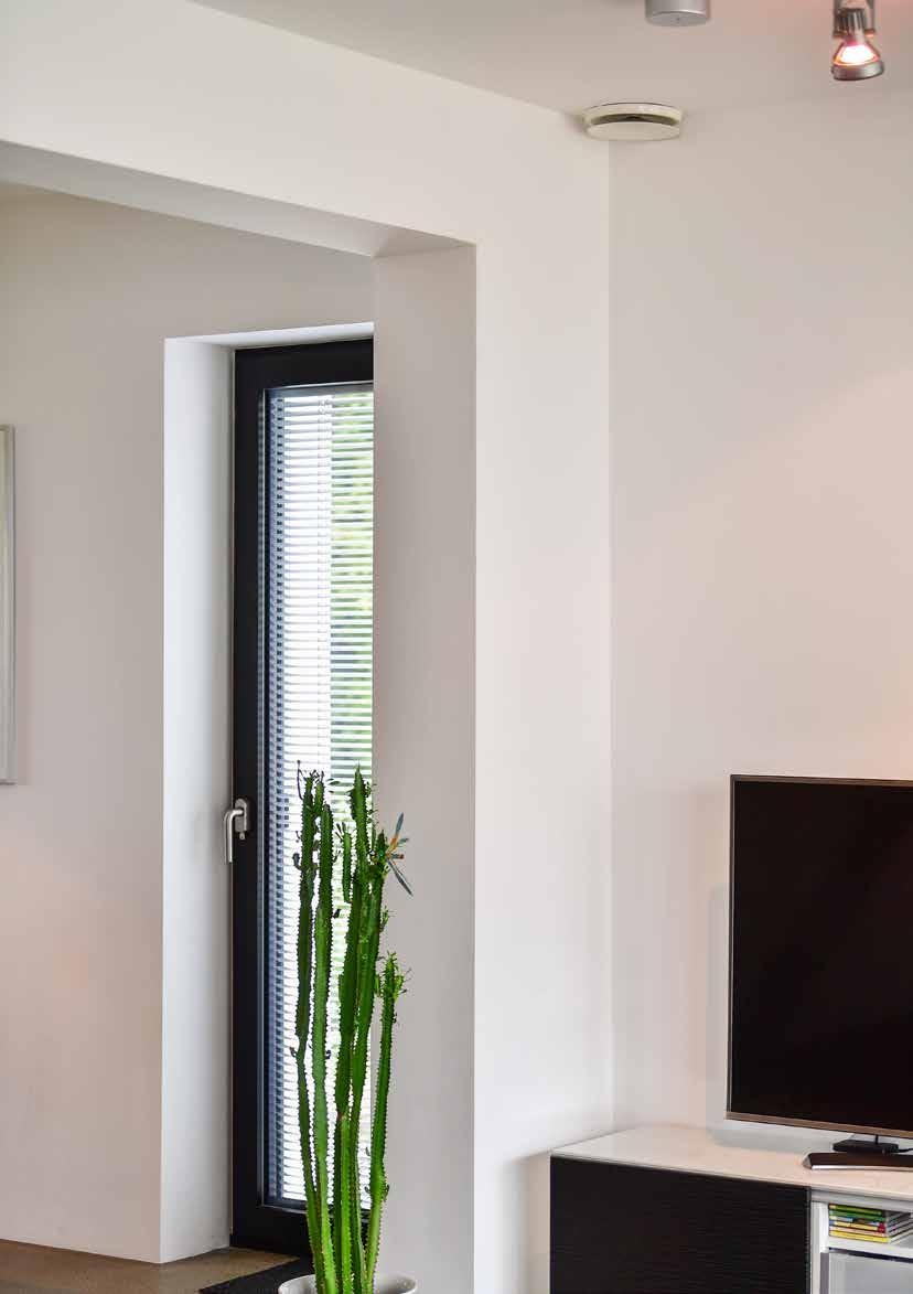
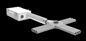
Drawings one to four show the connection of TUBE F distributors to ceiling or floor-mounted units for horizontal installation.
Advertisement
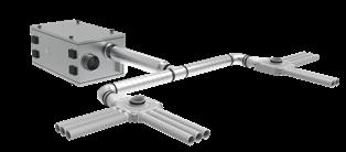
Figure 1 consisting of: VSR150 + SCD + adapter + distributor
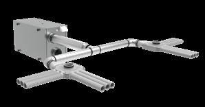
Figure 3 consisting of: VSR300 upright + SCD + T-piece + 2 adapters + 2 distributors Figure 2 consisting of: VSR300 + SCD + T-piece + 2 adapters + 2 distributors
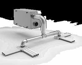
Figure 4 consisting of: VSR300 upright + SCD 90° + T-piece + 2 distributors
Connection of a duct system vertically to a wall unit Vertical connection for installing TUBE F pipes in the building storeys: either under, in, or above the ceiling.
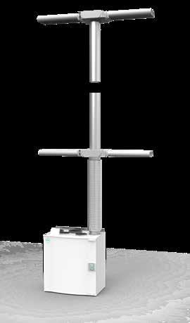
Figure 5 consisting of: VTR300 + SCD + spiral + 2 distributors TUBE F manifold connection under the ceiling to the ventilation unit with transition piece from DN125 directly to the manifold.
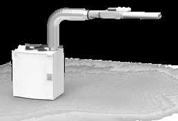
Figure 6 consisting of: VTR300 + SCD 90° + adapter + distributor
Folded spiral seam duct connection to ventilation unit with air volume split between two distributors.
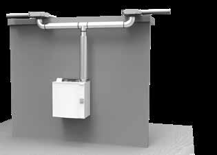
Figure 7 consisting of: VTR300 + SCD + T-piece + 2 distributors
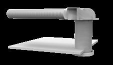
Figure 8 consisting of: Diverter 3xDN63 + TFF
Anschluss von Ventilen
Installing valves under a suspended ceiling: the TUBE F pipe can be laid within the ceiling or suspended below it. The length of the spacer between the diverter and the valve can be adapted.
Installing TUBE F and valve in a plasterboard wall: appropriate Systemair valves are available for direct installation in the diverter or into the spacer.
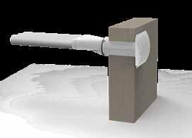
Figure 10 consisting of: Adapter + diverter + BOR-S Figure 9 consisting of: Diverter 3xDN63 + BOR-S
Installing TUBE F under the ceiling: a transition piece from Flex+ to DN125 can be used when installing TUBE F below the ceiling and connecting a valve on the rear side of the wall. An additional spacer can be used if necessary.