6 minute read
Park Landform
Park Landform
Now it’s time to work on the park. In this tutorial you will give the park a personality of its own. You will learn to generate terrain using three separate Sandbox tools: From Scratch, Drape, and Smoove. In combination, they allow you to generate smooth terrain fitting into a specific site plan location. The height or depth of the terrain is easily controlled, and you will learn to snap the terrain to the tops of walls and edges.
Advertisement
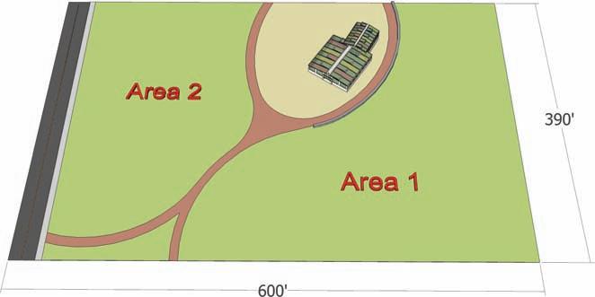
Download from 3D Warehouse and open model: Park_Landform 1. Review the base model. For this tutorial, you will apply From Scratch, Drape, and Smoove to Areas 1 and 2 to generate simulated terrain.
2. Directly adjacent to the park Flatwork Base model, draw a grid using From Scratch. The grid should be 400´ × 600´ with 10´ × 10´ grid spacing.
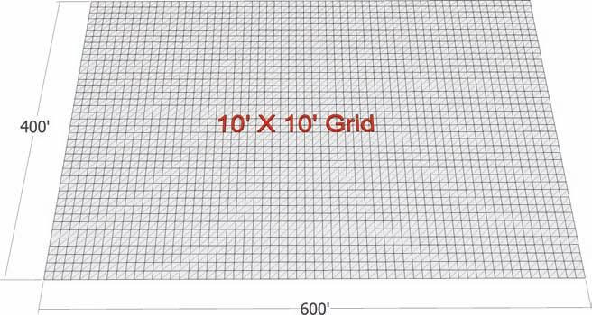
3. Select the surfaces of Area 1 and Area 2. With both surfaces selected, right-click and convert them into a single group. Move the group and place it over the From Scratch grid created in step 2. Ensure that the surface areas of Areas 1 and 2 fit within the bounds of the From Scratch grid.
4. Move the Area 1 and 2 group that you placed on the grid upward on the vertical axis to sit directly above the grid.

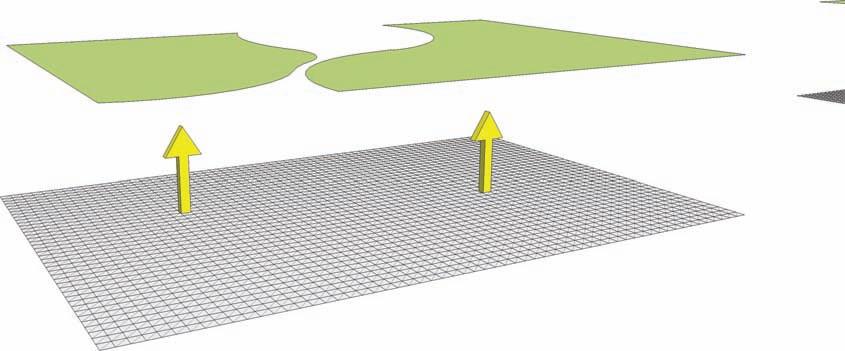
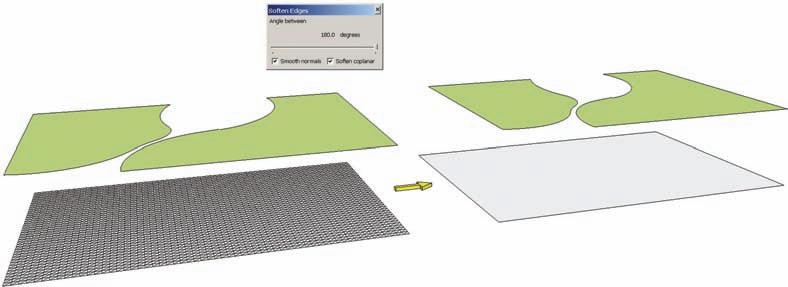
5. Select the From Scratch grid, right-click, and select Soften/Smooth Edges. Set the tab to the far right and check the Soften Coplaner box. This will cause the grid edges to be hidden.
6. Select the Area 1 and 2 group and activate the Drape command. Select the grid below the group by hovering over it. This will drape the edges of the group onto the grid. Enter the From Scratch grid instance (it is a group). The draped edges should have subdivided the grid face.
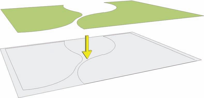
7. In some cases, the Drape command will not subdivide the grid face. A gap at the bottomright corner in the edge work prevents the face from being subdivided. Enter the Grid group instance to fix the problem.
Gap
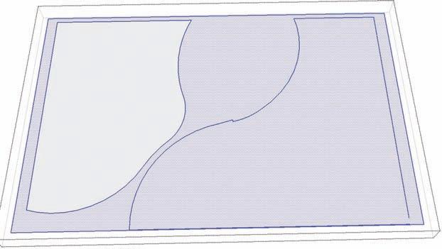
8. In the grid instance, add an edge connecting the endpoints where the gap is located.
Make sure the added edge subdivides the face.
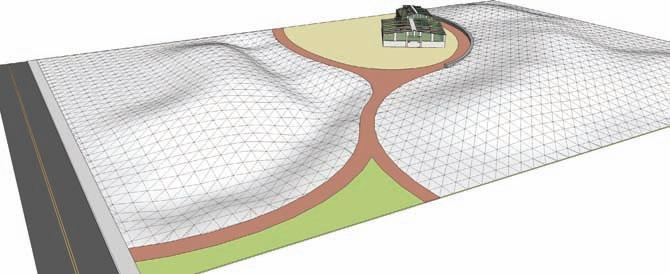
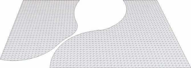
9. Delete the Area 1 and Area 2 group located above the From Scratch grid. Next, enter the grid instance and delete the edges and faces of the grid outside the surface areas that define Area 1 and Area 2. Once the extra faces are deleted, toggle on Hidden Geometry (View > Hidden Geometry). With the hidden geometry visible, the grid lines are shown
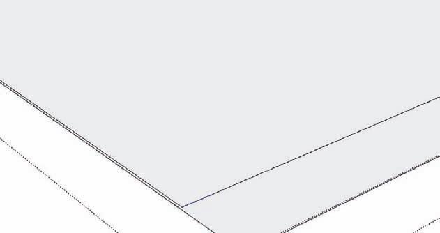
and can now be manipulated. The form of the From Scratch grid conforms to that of the site plan.
10. Select the cut-out From Scratch grid and place it back into the Flatwork Base. Use the corners of the grid to snap to a known corner or location of the Flatwork Base. Once the grid is in place, you are now ready to manipulate the geometry to simulate terrain using the Smoove tool.
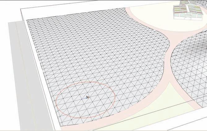
11. Enter the grid instance. Activate the Smoove tool and set the Smoove tool Radius to 60´. Start with Area 1 and activate the tool and pull the surface upward 10´ by entering the value in the VCB. With the Smoove tool circle active, hover over a location of the grid. Select the location by left-clicking. Pull the surface upward. Before clicking again,
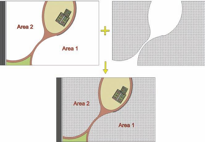
enter a value in the VCB to generate a specific height. Using the Smoove tool to generate specific heights can take some practice to master.
12. Move the Smoove tool to the approximate outer edge of the pulled-up faces and doubleclick. This will repeat the last Smoove command and raise another “mound” to the same height as the first one. This is one method of using the Smoove tool to create a constant and level grade.
13. Continue to generate the mound started in steps 10 and 11. Repeat step 11 to create a series of mounds. To generate a smooth terrain, when repeating the Smoove command on the next set of faces, locate the Smoove tool circle so the outer edge of the Smoove


circle is located approximately over the highest part of the adjacent mound. Then repeat the command (double-click). This will elevate the top of the new faces to match the adjacent mound without creating a “saddle” or gap between the landforms. Try and create a landform that snakes its way through Area 1 and maintains a regular height, without too many gaps or saddles.
14. Next, you will use the Smoove tool to snap the grid surface to the top of a wall so that the wall “retains” the terrain.
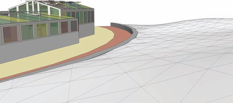
Locate the wall adjacent to the path and building in Area 1. Adjust the Smoove tool Radius to 30´. Place the Smoove tool over the faces directly adjacent to the wall. Activate the Smoove tool and pull the faces upward. The Smoove tool will allow you to snap to an inference point at the top of the wall. This will bring the grid surface up to match the wall height. Repeat this step, snapping the grid to the top of the wall face and creating a consistent grade along the top of the wall edge.

Wall
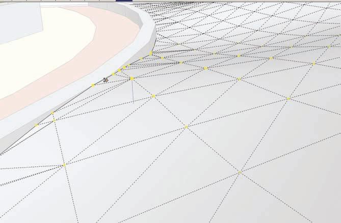
The grid surface is now contoured to the wall, creating a simulated retaining wall. This method can be adapted to be used to snap the grid to the vertical surfaces of buildings and other objects.
Wall
15. The Smoove tool can also be used to create swales.
a. Set the Smoove tool to 55´. In a location adjacent to the trail in Area 2, indent the grid faces enough to make a gentle depression. b. Move the Smoove tool over to the edge of the depression and double-click to repeat the exact depth of the indent.
This is identical to creating the landform in step 13. Like the landform, the depth of the indent can be be assigned by entering a value in the VCB.
16. Continue to repeat step 14, creating a swale in the area adjacent to the path.
17. Adjacent to the swale in Area 2, practice creating some gently uplifting grades with the Smoove tool. Practice adjusting the size of the Smoove tool radius. The goal is to create gently sloping and smooth landforms simulating terrain.
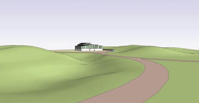
18. Once you’ve completed the simulated contour, turn off Hidden Geometry and add a green color to the surfaces.

