2 minute read
Adding New Details
Fig. 19-45: Inserted trees after Randor is applied.
Adding New Details
Advertisement
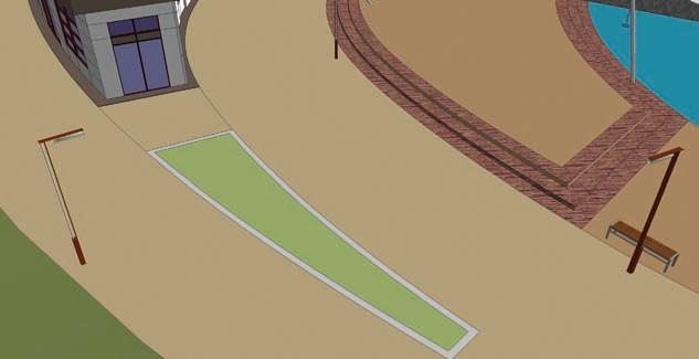
The Flatwork Base can still be adjusted and modeled. In the example images, the lawn area adjacent to the site building is further subdivided with the line tool to create a small planting area (Fig. 19-46).
The planting surface is offset to create a wall. The wall and planter are then given color and volume (Fig. 19-47, Fig. 19-48).
Small flowers components are placed in the planter. Each type is placed on its own layer (Fig. 19-49).

Fig. 19-46: The lawn area near the building will be adjusted to add more detail to the model.


Fig. 19-47: The lawn area is further subdivided into smaller areas. Then the interior of the lawn is offset by 8˝ to create a wall surface. Colors are adjusted for the wall and the interior planting surface.
Fig. 19-48: The wall and planting surface are Push/Pulled to create volume.
Fig. 19-49: Flower components are placed in the planter. Each shrub type is on its own layer.
The flower massings are then randomized using the Randor script (Fig. 19-50).

Fig. 19-50: To create a more natural-looking habitat, Randor is applied to the flower components. The flowers used here are from Form Fonts.
Similarly, traffic and road striping can be included. Draft the appropriate shapes onto the Flatwork Base (Fig. 19-51). Convert them into components, add color, copy, and arrange the components to simulate a road or pedestrian crossing (Fig. 19-52 through 19-54).

Fig. 19-51: Using the Line tool, subdivide a surface on the road. Fig. 19-52: The subdivided surface is then converted into a component.
Fig. 19-53: Color is added to the component. In this example, the white color creates a pedestrian crossing stripe.


Fig. 19-54: The Pedestrian Crossing Stripe component is then copied and arranged to simulate a pedestrian crossing.
There are many ways to add detail to the Flatwork Base. Typically, they are added through drafting, offsetting lines, providing color, and adding volume (Fig. 19-55, Fig. 19-56).

Fig. 19-55: The entire road surface is offset with the Offset tool. The offset lines are brought closer together to create a center traffic dividing line. The offset face needs to be further subdivided and “cleaned up” (not shown) to make sure it is a separate face from the road.
Fig. 19-56: Color is added to the subdivided face to simulate a center road stripe.


