14 minute read
Chapter 5 The Professional’s SketchUp Template


SketchUp provides several default templates that are excellent to use for learning, but ultimately not fit for professional use. Your default template in SketchUp should do more than just paint a pretty picture; it should also make modeling easier and reveal deeper levels of information stored within your model. You can customize your own SketchUp template by optimizing the model settings, creating utility scenes and styles, and adding default layers that will fit any design project.
B AS e Te MP l AT e
Advertisement
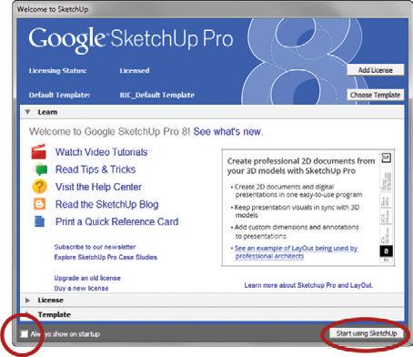
Start by opening SketchUp. If you see the Welcome to SketchUp window, uncheck the Always Show on Startup box in the bottom-left corner of the window (Figure 5.1). The Welcome to SketchUp window is designed to introduce first-time users to SketchUp and is not necessary for a professional. Close the Welcome to SketchUp window by clicking on the Start Using SketchUp button.
To select a template, click on the Window (SketchUp on Mac) drop-down menu and choose Preferences, then click on the Template tab. Find the Plan View – Feet and Inches template, click on it, and choose OK.
Click on the File drop-down menu and choose New to start a new model using the Plan View – Feet and Inches template. To see the new template, you will always need to start a new file. This template starts off in a clean white background, and the default units are inches. Now that you have selected a stock default template, you are going to customize it and save it as your own default template. Click on the File drop-down menu and choose save, navigate to your RESOURCES/TEMPLATES folder and name the file BIC_Default Template.skp.
Mo D el i nfo
Figure 5.1
Window offers links to learning resources, licensing information, and the default template. All of this information and more is available in the Help menu and at SketchUp.com.
The Model Info settings travel with your model. In this section, you will modify only the settings that will help make your modeling faster and more efficient. Keep in mind that all of the Model Info settings can be changed once a new model is started. To get started, click on the Window drop-down menu and choose Model Info.
Animation
Unless you are creating an animation, you won’t need to see scene transitions while you’re designing in SketchUp. Sure, they look cool, but they also kill a couple of seconds every time you change to a different scene. As a professional, you need instant information, so go to the Animation tab and uncheck the Enable Scene Transitions check box (Figure 5.2).

Dimensions
Dimensions are best shown in LayOut, where you have full control of placement, size, scale, font, and style. In some instances, you may find it help ful to add dimensions to a quick sketch in SketchUp. When you’re adding dimensions in SketchUp, make sure to apply your own style to set your presentations apart from other SketchUp users. Choose your font style and size from the Dimensions tab (Figure 5.4). Also choose your favorite arrow type and alignment.
When there is not enough room to clearly display the dimensions, you can use the Expert Dimension settings to control whether or not to display them. Typically, there is no “best” default setting for the Expert Dimension settings. You should modify the settings on a case-by-case basis.

Rendering
Enabling anti-aliased textures may speed up SketchUp’s performance (Figure 5.5).

Text
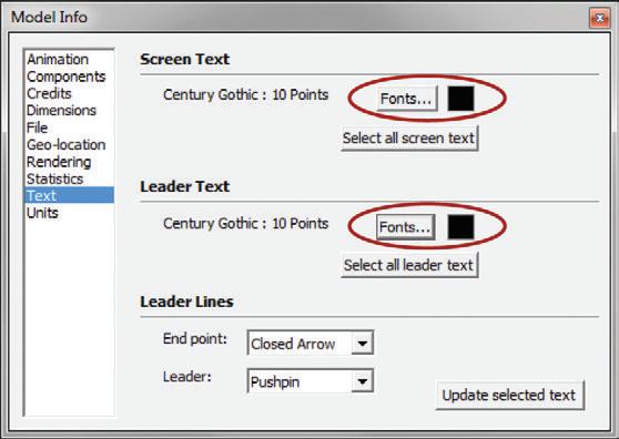
Similar to dimensions, text annotations are preferably added within LayOut; although they are not used nearly as much within SketchUp, you can still customize the text style within SketchUp. Set your favorite font within the Text tab, which will probably match the Dimensions Text settings (Figure 5.6).
Units
The default units are set to inches in the Plan View – Feet and Inches template. By thinking in terms of inches, you can save time while you are modeling. For example, to draw a line at five-feet-six-inches long, rather than typing 5 f6 g and pressing the Enter key, you can just type 66 and press Enter. In this case, by thinking in inches, you cut the number of keystrokes in half. Saving three keystrokes may not seem significant, but think of the hundreds of commands you perform in an hour when you are using SketchUp.
The Model’s Precision setting indicates the number of units that will display in the Measurements dialog box. The Model’s Precision setting can be overridden by entering a precise dimension into the Measurements dialog box during an operation. For example, if the model’s accuracy is set to 1/8 g, and you enter a dimension that ends in 1/64 g, that line will actually be drawn to the 1/64 g, but when measured will be rounded to the nearest 1/8 g because of the precision setting. Typically, a Model’s Precision is set to the most accurate setting of 1/64 g

TIP Professionals should always have the model accuracy set to the highest tolerance of 1/64g (figure 5.7). i t is important that the model itself has the most precise dimensions possible. Then, if necessary, you can use less precise dimensions in lay o ut to clean up fractional dimensions for schematic presentations. o nce you begin a model, do not change the Precision setting.
Length snapping limits the dimensions of an object drawn in SketchUp to predefined intervals. Enabling length snapping is the best way to keep your dimensions clean. For example, when designing on a very loose preliminary sketch of a site plan or building footprint, you might set the length snapping to 6 g or 12 g to keep the dimensions round and clean. If you are designing with masonry block, set the length snapping to 8” to design within the limitations of the material. By entering precise dimensions in the Measurements dialog box, you can override length snapping during any operation.
S TA n DA r D lAyer S
A logical set of layers will help you keep a model organized, which will prove helpful when you are exporting backgrounds for consultants, moving to other CAD programs, rendering with a photorealistic plugin, and creating construction documents in LayOut. Figure 5.8 displays a list of standard layers used to create SketchUp models with these tasks in mind. These are the official layers of The SketchUp Workflow for Architecture. Note that the layers are organized into three categories: CONCEPTUAL, ARCHITECTURAL, and SITE. ARCHITECTURAL and SITE layers are nouns, often named after actual physical objects. CONCEPTUAL layers are adjectives that describe the ARCHITECTURAL and SITE layers. CONCEPTUAL layers are more abstract and intangible.

You’ll learn more about how and where to apply these layers later in this book. Right now it is important to create your customized default template and workspace so that later everything will flow easily. Add these layers to your template now. Assign a green to the CONC - New layer and assign a gray to the CONC - Existing layer. All other layers can be assigned the color black, or disregarded.
Now save your SketchUp model into the ACTIVE PROJECTS/RESOURCES/Templates folder. These new files need to be saved shortly after you first start them. SketchUp’s autosave feature will not kick in until you have saved the model once yourself.
S T yle S
If you have used SketchUp for even a small amount of time, you probably have explored the enticing visual effects offered by styles. Styles allow you to completely alter the appearance of your model without affecting the underlying geometry. For instance, you can add sketchy lines, blueprint colored faces, canvas watermarks, and different color backgrounds without modifying any geometry or materials. These are all great visual effects you can use for presentations, but you’ll pay the price by slowing down your computer when using complex styles.
What if a style could also do the opposite, increase computer performance by turning off the resource-hogging visual features? In this way, styles can also be used as a tool rather than just an attractive visual effect. Styles control properties that can make your models easier to work on, optimize your system’s performance, and visually communicate deeper levels of information stored within the model (Figure 5.9). In the next section, you will explore styles by creating several utility and presentation styles, including DESIGN, LINE DRAWING, PRESENTATION, COLOR BY AXIS, COLOR BY FACE, and COLOR BY LAYER. After you create the styles, you will combine them with the power of scenes to make your timesaving default template complete.
DeSign Style
The DESIGN style turns off all of the bells and whistles that make SketchUp models look great but at the same time heavily tax the processor and graphics card, thereby slowing the system. When working on a model, you want to be fast and effective. It is important to have a default state where you know your machine is going to perform its best. This optimized default state will utilize the DESIGN utility style.
Click on the Create New Style button to add a new style to your template model and name it “DESIGN”. Click on the Edit tab and adjust the settings as shown in Figure 5.10. Click on the Update button to save the changes and the watermark will go away, indicating that everything has been saved. The DESIGN utility style is complete.

line Dr AWing Style
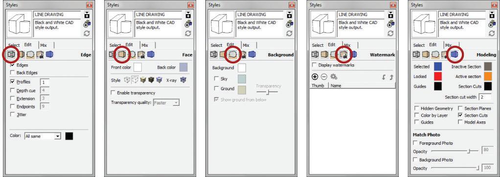
The LINE DRAWING style presents all geometry in simple black lines on a white background. This style is ideal for creating CAD-type 2D output as typically seen in construction documents.
Click on the Create New Style button to add a new style to your template model and name it LINE DRAWING. Click on the Edit tab and adjust the settings as shown in Figure 5.11. Click on the Update button to save the changes and the watermark will go away, indicating that everything has been saved. The LINE DRAWING utility style is complete.

PreSenTATion Style
The PRESENTATION style is the opposite of the DESIGN style in that it turns on all of the desired visual bells and whistles. The PRESENTATION settings typically utilize sketchy edges and more complicated effects for a final rendering. Start with what is shown here, then get creative and make your own PRESENTATION style.
Click on the create new style button to add a new style to your template model and and name it PRESENTATION. Click on the Edit tab and adjust the settings as shown in Figure 5.12. Click on the Update button to save the changes and the watermark will go away, indicating that everything has been saved. The PRESENTATION utility style is complete.
The PRESENTATION style settings
TIP you can also use the Mix tab to drag and drop your favorite properties into the current style. once you are satisfied, be sure to click on the Update button to update the style. See chapter 7 “SketchUp collections”, creating a Style section, for more information on using the Mix tab..

color By AXiS Style
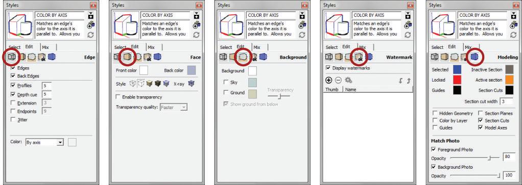
The COLOR BY AXIS style can help you troubleshoot a problematic model. If you are tracing lines and a surface will not reheal, often the problem is an edge that is off axis. By switching to the COLOR BY AXIS utility style, all of the edges will be colored by the same as the axis the edge is parallel to and all surfaces will be white. It will become immediately clear which lines are causing the problem because any off axis edge will be black.
Click on the create new style button to add a new style to your template model and name it COLOR BY AXIS. Click on the Edit tab and adjust the settings as shown in Figure 5.13. Click the Update button to save the changes and the watermark will go away, indicating that everything has been saved. The COLOR BY AXIS utility style is complete.

color By fAce Style
The COLOR BY FACE utility style displays the geometry of the side of the surface that is showing, the front or the back. Viewing geometry in this way will help you prepare a model for photorealistic rendering.
Click on the create new style button to add a new style to your template model and name it COLOR BY FACE. Click on the Edit tab and adjust the settings as shown in Figure 5.14. Click on the Update button to save the changes and the watermark will go away, indicating that everything has been saved. The COLOR BY FACE utility style is complete.
color By l Ayer Style
The COLOR BY LAYER utility style displays geometry according to the color assigned to the geometry’s layer. Viewing geometry in this way will visually show you deeper levels of information stored in your model’s layers.
Click on the create new style button to add a new style to your template model and name it COLOR BY LAYER. Click on the Edit tab and adjust the settings as shown in Figure 5.15. Click on the Update button to save the changes and the watermark will go away, indicating that everything has been saved. The COLOR BY LAYER utility style is complete.

See www.suexch.com for additional styles that you might want to make, but don't necessarily want to attach to a utility scene—for example, Hatch-50, Hatch-25, Hatch-75, Hatch-100, Line Drawing-50, Line Drawing-Red, and Mask.
U T ili T y Scene S
Styles are helpful by themselves, but the ability to attach a style—along with layer states and many other settings—to a scene, means that all of these settings are readily available through the Scene tabs at the top of your screen. Utility scenes are the core of a professional’s template. Utility scenes are included in a template and used as a tool, rather than merely a visually attractive presentation view (Figure 5.16).
Using scenes, you have the ability to control properties such as camera location, hidden geometry, visible layers, active section planes, fog, shadow settings, axes locations, and most importantly styles. You can combine the best features of both scenes and styles to make an extremely useful and efficient template and get the most out of your model.
TIP in the Scenes window, you can determine whether or not to use thumbnail images. click on the context arrow at the top-right corner of the Scenes window and uncheck Use Scene Thumbnails. Scene thumbnails can be helpful at times, but generating them requires extra rendering time and computer resources and you do not need them.
layer State Scenes
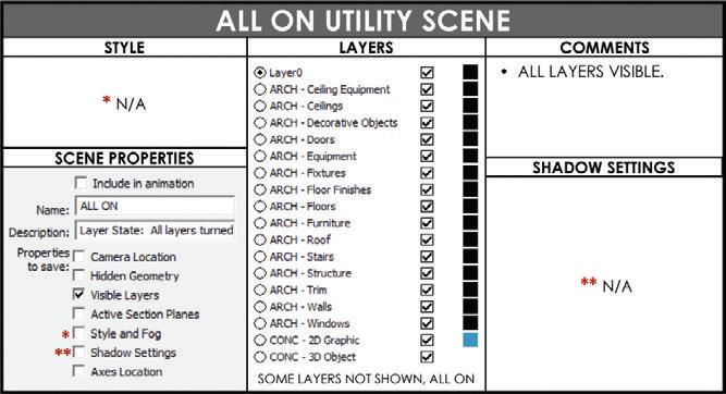
Layer state scenes save only the visible layers within scene’s properties to save. They are the switches that turn on and turn off the information you want to view. Click on the Add Scene button in the scenes dialog, then adjust the settings for each of the utility scenes. The ALL ON utility scene makes all layers visible (Figure 5.17).
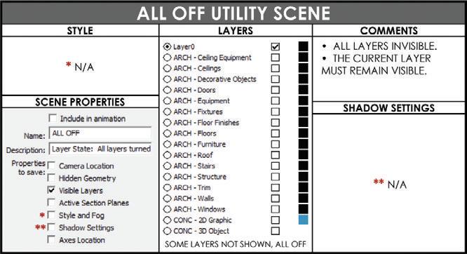
The ALL OFF utility scene makes all layers invisible (Figure 5.18).
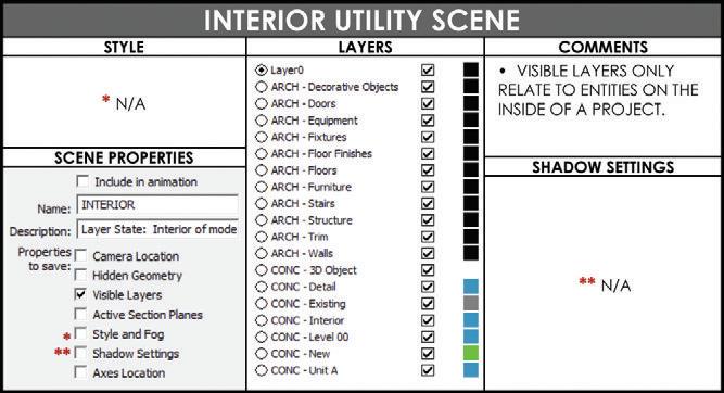
The INTERIOR utility scene turns on the layers and, in turn, the geometry that relates to the inside of a building (Figure 5.19). This is helpful for working on the plan without having exterior walls blocking your view of the interior.
The EXTERIOR utility scene turns on the layers and, in turn, the geometry that relates to the outside of a building (Figure 5.20). This is helpful for designing the exterior elevations without having the site and interior of the model turned on, thereby slowing your computer.
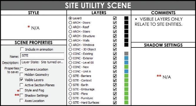
The SITE utility scene turns on the geometry that relates to the outside of a building and the site (Figure 5.21). This is helpful for working on the landscape plan without having the interior of the model turned on, thereby slowing your computer.

Presentation Scenes
Presentation scenes are used to display the model in a final format, either in print or on screen. Typically, you will use these scenes before you create additional scenes to send to LayOut.
The DESIGN utility scene combines the settings of the DESIGN utility style with additional performance-enhancing settings of scenes (Figure 5.22). Use this utility scene when you’re working on the model and navigating a model in real time for on-screen presentations.
The 3D PERSPECTIVE utility scene sets the view to the desired final-presentation state (Figure 5.23). Typically, this scene is determined by your personal presentation preferences. Don’t hesitate to modify the suggested settings.
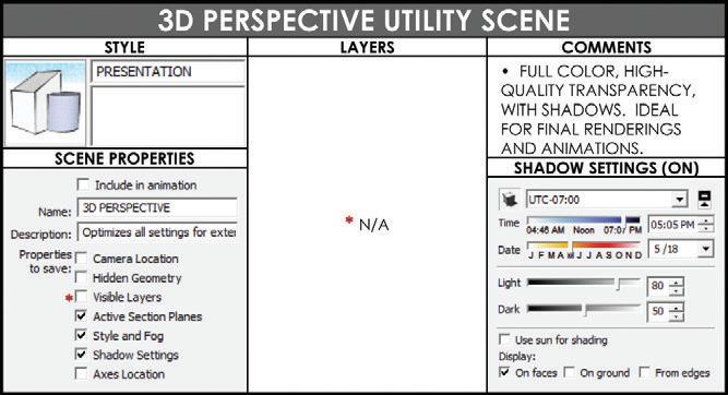

TIP When you’re creating an interior scene, brighten up the ceilings with Shadow settings. Set the light slider to 20 and the Dark slider to 100. Set the time of day to noon and make sure the Use Sun for Shading check box is checked. These settings eliminate the “gray ceiling effect” often seen in interior SketchUp renderings.
The 2D DRAWING scene switches to the LINE DRAWING style to display the geometry as black lines on a white background (Figure 5.24). This scene is also determined by your personal preference for creating CAD-type output.
Diagrammatic Scenes

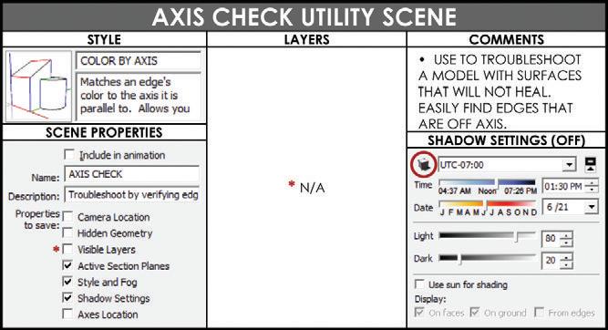
Diagrammatic scenes display the model in ways that visually communicate more information. The AXIS CHECK utility scene can help you troubleshoot a problematic model (Figure 5.25). If you are tracing lines and a surface will not reheal, the problem is frequently an edge that is off axis. When you switch to the AXIS CHECK utility scene, all of the edges will be colored by axis and all of the surfaces will be white. It will become immediately apparent which lines are causing the problem because they will be black.
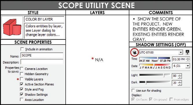
The SCOPE utility scene displays the model colored by new and existing objects based on the CONC - New and CONC - Existing layer’s assigned color (Figure 5.26). The type of diagram that is generated is perfect for explaining the scope of a project to a new team member. This diagram gives an overall snapshot of the amount of demolition and construction to be completed.
The ORIENT FACES utility scene displays the model colored by faces (Figure 5.27). Using the diagram, you can easily right-click on the faces and reverse them until all of the fronts are facing out. Your entire model should be pink, which means that all fronts are facing out and is best for photorealistic rendering.

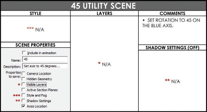
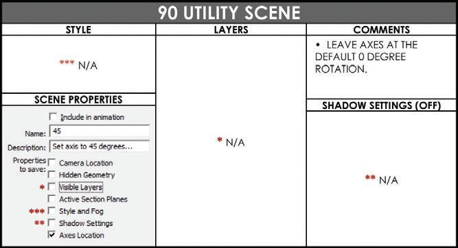
The 45 and 90 utility scenes make it easier for you to create plans that follow two or more grids (Figure 5.28). These types of scenes save the location and rotation of the axes. Keep in mind that in this example you are switching the grid to 45 degrees, but you could use any angle of grid shift.
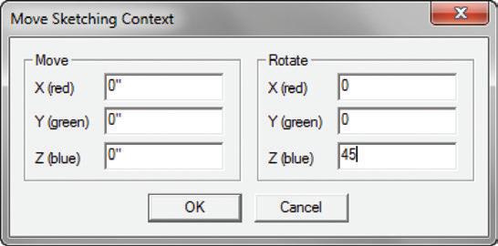
Now create the 45-degree scene. First, right-click on any axis and select Move. Go to the Move Sketching Context dialog box and change the Z rotation to 45. This will rotate the axes around the blue axis to a 45-degree angle. See Figure 5.29 and Figure 5.30.
Saving as a Template
Now that you have added utility scenes, styles, and default layers to the base template, save it as your own custom template. Before saving, click on the ALL ON Utility Scene, then Click on the DESIGN Utility scene to set your template to the ideal default state. Click on the File drop-down menu and select Save to update the saved version in your RESOURCES/ Templates folder. Now, click on the Window (SketchUp on Mac) drop-down menu and choose Preferences. Click on the Template tab, click the Browse button, and navigate to your templates in the RESOURCES/Templates folder. Select the BIC_Default Template.skp and click Open.
When you choose a new template, you must always start a new document to see the template activate. Click on the File drop-down menu and select New. You will see the new active default template with all of the custom layers, styles, and scenes.
c h APT er Poin TS
☑ The Bright Ideas Consultants default template is available for download at www .suexch.com
☑ Not all styles need to have a scene. Some of the hatching and 2D drawing styles will be selected when the scene is created. This is up to the user’s discretion based on the type of design you do, whether or not you need each of these utility scenes.
☑ The utility styles and utility scenes created in this chapter are only a few possibilities. Experiment with other properties attached to styles and scenes to determine how to make your SketchUp workflow even more efficient.
☑ All utility styles, scenes, and layer states should be modified to fit your project type. A default template is a constant work in progress.


