13 minute read
Site Analysis: Documenting an Existing Building


Creatingaccurate as-built drawings is a critical early step in the design process. When you’re making decisions about new construction, it is important to be well informed about existing conditions. The techniques in this section will give you an organized plan of attack for measuring and documenting any building.
The Pro J ec T
Advertisement
For this exercise, you will prepare for a site visit to a house where the client would like to remodel the main floor and add a new kitchen, bathroom configuration, and master bedroom suite. You will record and document the existing conditions using SketchUp and LayOut to expedite the process.
Preparing for a Site Visit
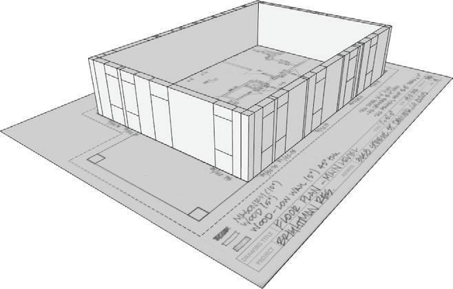
Often when visiting a site, you’ll spend hours pacing off the building, sketching the footprint, and trying to record everything on one landscape page—or even trickier, you might try to break things up on multiple pages. This is a difficult task! Fortunately, there is a way to create your initial field sketch in 5 minutes—before you even leave the office. Follow the steps in this section to trace the building footprint in SketchUp and print at an ideal scale from LayOut onto custom grid paper.
Adding the location
To add the location, follow these steps:
1. Open SketchUp and start a new model.
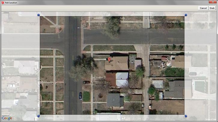
2. Click on the File drop-down menu and select Geo-Location c Add Location. In the search bar, type 3458 Steele St, Denver, Co, then press Enter (Figure 17.1).
3. Once you track down the correct residence, click the Select Region button.
4. Use the pins to position the selection area over the entire property (Figure 17.2).
5. Click the Grab button to import the selected Google Earth Snapshot and Terrain.

creating the Building footprint
To create the building footprint, follow these steps:
1. Click the File drop-down menu and choose Geo-Location, and uncheck the Show Terrain option. To do this, you could also use the Toggle Terrain button on the Google toolbar.
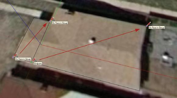
2. Trace the roof outline using the Rectangle tool. For this task, it is faster to use the Rectangle tool to trace over each portion of the roof rather than using the line tool (Figure 17.3).
TIP enable length Snapping to make what seem to be loose sketches much cleaner with precise round measurements. Typically, when you’re tracing a site, a 1 g tolerance for length Snapping is ideal. click on the Window drop-down menu and choose Model info. Then click on the Units tab to adjust the length snapping features.
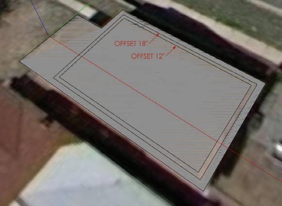
3. Using the Offset tool, offset the roof outline by 18 g to create the exterior wall line (Figure 17.4).
4. Offset the exterior wall line by 12 g to create the interior wall line (Figure 17.4).
5. Use the Eraser tool to delete any extra unwanted edges.
6. Save the model to your TEMP folder or appropriate project folder as BIC_3458 Steele St – Existing Conditions.skp
7. Using the Select tool, triple-click on the sketch of the building footprint to select all the connected geometry.
Chapter 17: Site Analysis: Documenting an Existing Building
8. Click on the Edit drop-down menu and choose Make Group.
9. Click on the Edit drop-down menu and choose Copy.
Pasting into layout
Typically, graph paper lines are spaced apart at 1/10 g, 1/8 g or 1/4 g, which can make field sketching difficult if the drawing size is not suited to one of these scales. LayOut allows you to create a custom grid that matches any architectural scale, even a custom or irregular scale. Just follow these steps:
1. Start a new LayOut presentation using the BIC_8.5x11 – Landscape template.
2. Click on the Edit drop-down menu and choose Paste. The SketchUp geometry will be inserted into LayOut as a generic SketchUp model linked to the LayOut presentation, displayed in a viewport (Figure 17.5).
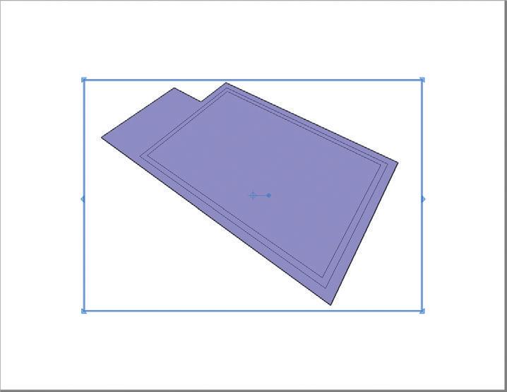
3. Expand the viewport to cover the entire page.
4. Select the new generic viewport and adjust the properties in the SketchUp Model Inspector, as shown in Figure 17.6.
creating an optimized Scale
The as-built sketch does not fit perfectly on the page at 1/8 g = 1 f-0 g; it is too small. At 1/4 g = 1 f-0 g, the drawing is too big. What you really need is an irregular scale that falls somewhere between these scales. In this section, you will create a custom scale in LayOut so that your as-built drawing is maximized on the page, giving you the most space to work with in the field.
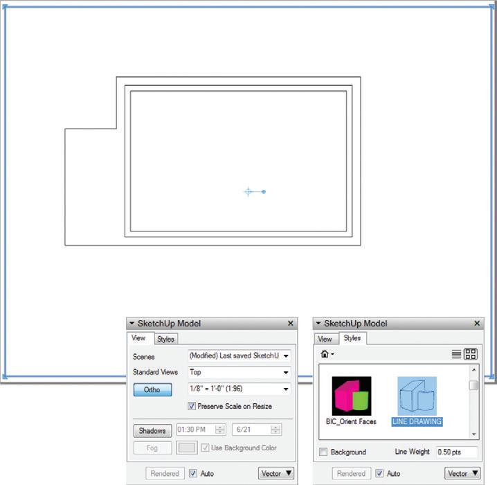
1. Experiment with different standard scales in the SketchUp Model Inspector. You’ll see that a standard scale does not work well for this drawing.
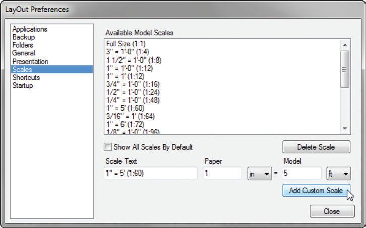
2. At the bottom of the Scale drop-down menu, click the Add Custom Scale button.
3. This automatically launches the LayOut Preferences dialogue box. Technically, 1/4 g scale is equivalent to 1 g = 4 f-0 g, so try to work one level up; 1 g = 5 f-0 g fits perfectly (Figure 17.7).
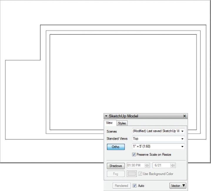
Matching the grid to Scale
Now that you have created an irregular scale to maximize your drawing size, you will want to match your grid to the irregular scale of 1 g = 5 f-0 g (Figure 17.9). This will make the task of field sketching faster, easier, and much more accurate. Follow these steps:
1. Click on the File drop-down menu and choose Document Setup. Click on the Grid tab in the left column.
2. Click the Show Grid check box to toggle on the grid visibility.
3. Set the Major Grid spacing to 1 g .
4. Set the number of divisions to 5.

5. While you have this tab open, check on the Print Grid feature.
Aligning the Drawing with the g rid
Now that the scale is set, you’ll want to align the drawing with the grid (Figure 17.10). Just follow these steps:
1. Right-click in the LayOut work area and check on the Grid Snap feature. This will allow you to perfectly align the drawing with the grid.
2. Using the Select tool, select the viewport. Click and drag on the Precise Move grip to pick it up, and then release to place it on the inside corner of the wall in your drawing.
3. Click and drag on the drawing within the viewport, and allow the Precise Move grip to snap to the grid.
TIP At this point you could explode the building outline plan and apply a more complex graphic style using the Shape Style inspector in layout. for instance, you could make the roof outline dashed and adjust line weights.
17: Site Analysis: Documenting an Existing Building

e xporting the PDf
Now that your building outline is ready for the field, you’ll need to export to PDF, print, and head to the site.
1. Click on the File drop-down menu and select Export c PDF.
2. Save this file in your TEMP folder, or in the EXPORTS folder in the appropriate project folder.
3. The PDF options dialog opens automatically. Adjust the settings as shown in Figure 17.11.

4. When the export finishes and the .pdf opens, click on the File drop-down menu and choose Print. Print a copy of the drawing for each floor that you intend to document, and make some extra copies just in case.

r ecor D ing f iel D n o T e S
Recording dimensions in the field can be a tricky task. The following tips will help you stay organized when you’re taking notes in the field and ultimately prepare your field notes for importing and efficient 3D modeling.
☑ Record the measurements only in inches, rather than feet and inches (Figure 17.12). This will ultimately make modeling in SketchUp easier. For instance, write 88.75 , rather than 7 f-4-3/4 g. This will save you room on the page and keystrokes in SketchUp.
☑ Note the inside wall-to-wall dimensions instead of trying to draw wall thicknesses at a small scale. If there are several different wall types/thicknesses, use a highlighter to call out the wall thicknesses from a wall type key. Alternatively, you can make a general note—for example, “all walls are 5 g unless otherwise noted”—rather than dimensioning every wall’s thickness (Figure 17.13).
☑ Give yourself plenty of room by always working at the largest scale possible. If the building is very large, it could make more sense to use a tabloid-size sheet or multiple lettersize sheets.
☑ Use general notes to minimize repetitive notes on the field notes drawing (Figure 17.14). Call out general ceiling heights, door heights, finishes, etc.
Figure 17.14 Use general notes to eliminate repetitive and ambiguous notes.
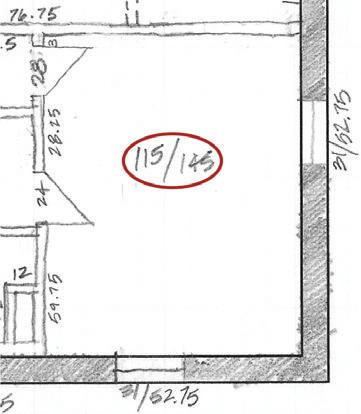
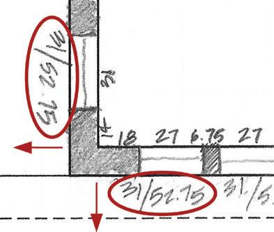
☑ Add the overall room dimensions in the center of the room in a drawing (Figure 17.15). Use the same X-distance/Y-distance format every time.
☑ Record the sill heights and window heights on the outer perimeter of the plan, with the text oriented to be read from the outside of the page (Figure 17.16). Use the format: Sill height/Head height.
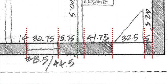
☑ Avoid using dimension lines. Record wall, window, and door dimensions within the building drawing oriented in line with the dimensions they define (Figure 17.17).
Overall room dimen - provide a reality check to insure that all measurements add up correctly.
Chapter 17: Site Analysis: Documenting an Existing Building
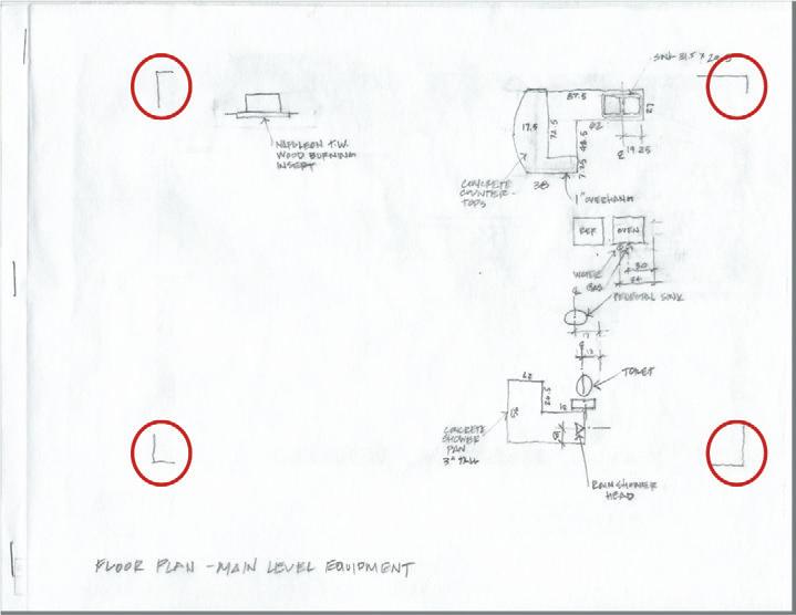
☑ Record the wall locations only on the main plan. Bring letter-sized tracing paper to document additional layers, such as equipment (Figure 17.18), reflected ceiling plans, framing, etc. This will help you keep your drawing clean and organized. Be sure to mark where each drawing sits by tracing the corners of your plan (Figure 17.19).
The A S -B U ilT 3D Mo D el
Creating the as-built 3D model is possibly the most important step in the design process for a renovation project. All design decisions will be made from this model, so it must be extremely accurate. Any mistakes made here will carry through every model and drawing you create, and ultimately these mistakes will drastically affect the actual construction!

Importing The Field Notes
To import your field notes, follow these steps:
1. Scan all the pages of your field notes and save them in the IMAGES folder for the project. To maintain your organization, create a subfolder in the IMAGES folder and name it YYMMDD_Field Measurements , using today's date. To complete this exercise you will use the scanned field notes from the class files folder.
2. In SketchUp, open the BIC_3458 Steele St - Existing Conditions.skp file.
3. In the Layers dialog, turn off the Google Earth Snapshot and Google Earth Terrain layers.
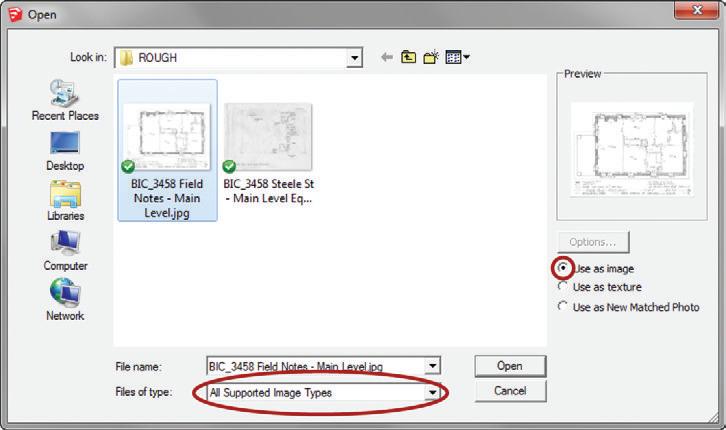
4. Click on the File drop-down menu and select Import. Set the Files of Type setting to All Supported Image Types. If you don’t, you won’t be able to see your scanned image files. Make sure the Use as Image radio button is activated for the import type (Figure 17.20).
5. Navigate to the TSWFA folder and select the BIC_3458 Steele St - Main Level Floor Plan.jpg scan and click the Open button.
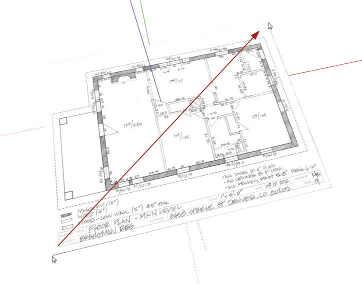
6. Click once to place the image, and then move your cursor away to scale the image. You don’t need to be exact right now because you will scale precisely in the next step (Figure 17.21). Click again to finish placing the image.
7. Right-click on the image and select Explode. Exploding an image converts it to a surface with a material applied to it. The material’s texture image is the imported image.
8. Double-click the surface, and then right-click and choose Make Group.
9. Select the new group containing the field notes; in the Entity Info dialog, assign the CONC – Background layer.
Scaling the field notes
After you insert the field notes, you’ll need to scale them.
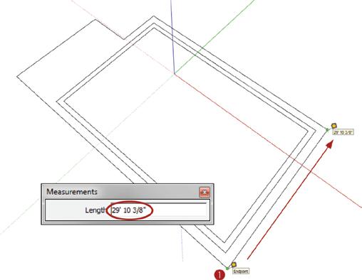
1. Activate the Tape Measure tool. Find a known dimension. Measure the overall distance of the building and remember that distance (Figure 17.22).
17: Site Analysis: Documenting an Existing Building
2. Using the Select tool, double-click into the Field Notes group.
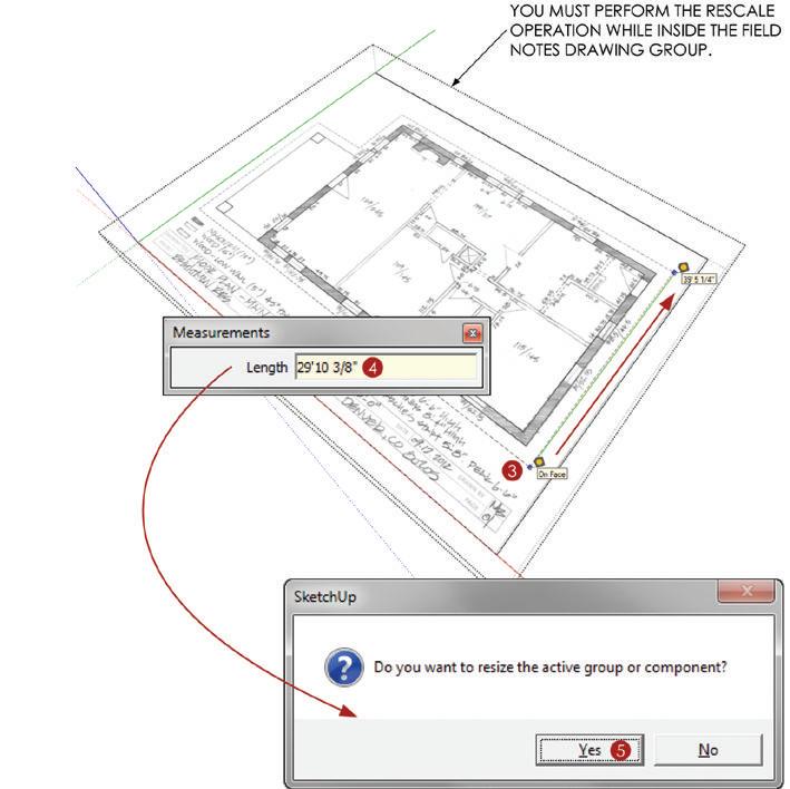
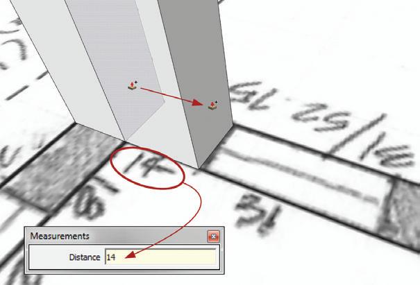
3. Using the Tape Measure tool, measure that same overall distance on the field notes (Figure 17.23).
4. Immediately after the second click, enter what the actual distance should be, then press Enter. This is the distance that you remembered from step 1, in this example 29' 10 3/8”, although on your model this distance might be slightly different.
5. SketchUp asks if you would like to “resize the active group or component.” Choose Yes. This sets the measurement to be the same as what you just typed in.
6. Close the Field Notes Drawing group.
7. Perform a precise move to align the field notes drawing with the original building footprint sketch (Figure 17.24).
8. Right-click on the Field Notes group and select Lock.
9. Delete the original building footprint sketch. You no longer need it.
10. Click on the File drop-down menu and choose Save.
Modeling from the field notes
Now you are ready to draft the existing conditions. The beauty of this technique is that there is no need to look back and forth between your field notes and the computer because your field notes are already in the model.
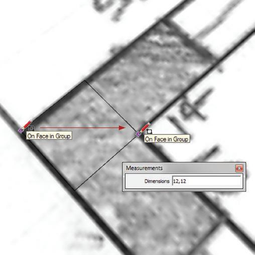
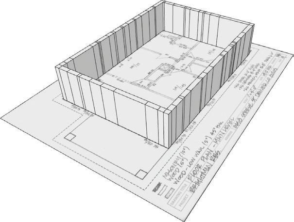
1. Draw a square at 12 g n 12 g in the corner of the plan (Figure 17.25).
2. Push/pull the square up to the recorded ceiling height of 8 f4 g (Figure 17.26).

3. Using the Push/Pull tool, extrude the plan horizontally (Figure 17.27, Figure 17.28). As you are push/pulling, tap the Ctrl key (Option key on Mac) to toggle the Create New Starting Face command. This leaves a copy of the starting face and edges behind and allows you to mark horizontal breaks and openings. Leave a starting face at every major opening, such as walls, doors, and windows.

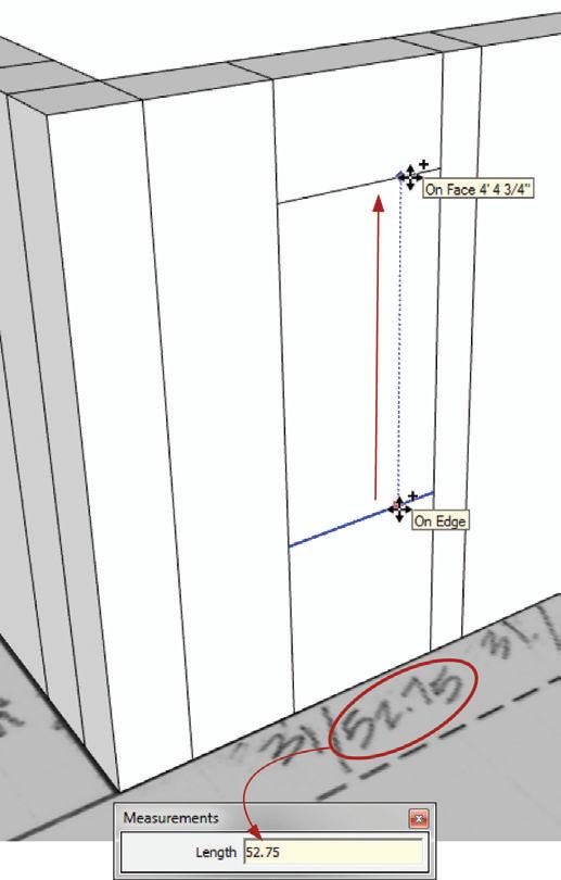
4. Navigate to the outside of the model. Use the Move tool to copy the bottom lines of the door and window openings up to the noted sill heights, and then again for the head heights (Figure 17.29, Figure 17.30, Figure 17.31).
TIP you can create the openings using several different methods. you could use the Tape Measure tool to create guides, and then use the rectangle or line tool to create the rest of the opening. Use the tools and methods that you find the most efficient.

5. Using the Eraser tool, delete all of the extra edges on the inside walls of the model, as well as any unwanted geometry on the outside walls. Leave behind all of the lines that define the openings.
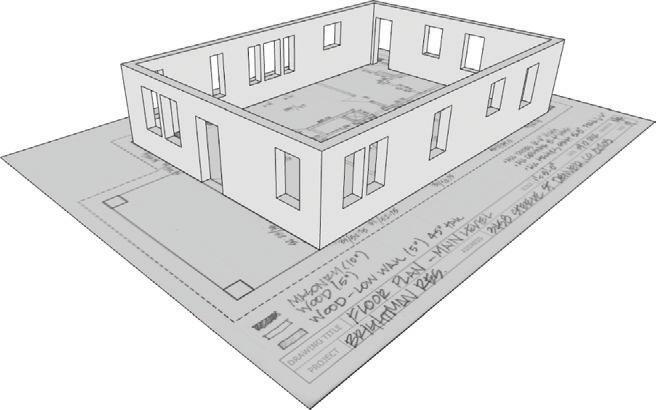
6. Use the Push/Pull tool to create all major openings as shown in Figure 17.32. Push from the outside of the house in. After creating the first opening, you can doubleclick on the other openings and use the memory of the Push/Pull tool.
7. Select all of the new walls, right-click on the selection, and choose Make Group.
8. Draw the interior walls using the same techniques. Leave a starting face at all major openings for the doors and arches, and to turn the corners. When you are finished, select all interior walls and make them a group as well.
Layering And Organizing
You need to organize your model from the moment you begin creating it and continue that organization throughout the process. To start organizing the model, follow these steps:
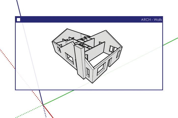
1. Select both groups of walls: interior and exterior.
2. Right-click on the selection and choose Make Group.
3. Right-click on the group and choose Entity Info.
4. In the Entity Info dialog, assign the ARCH – Walls layer to the group containing the walls (Figure 17.33).
5. Using the Select tool, double-click into the new group of walls. In the Entity Info dialog, assign the Exterior Walls group to the CONC – Exterior layer and assign the Interior Walls group to the CONC – Interior layer (Figure 17.34).
6. Double-click into the Exterior walls. Select all of the exterior walls, right-click on the selection and choose Make Group. Assign the group to the CONC – Existing layer, as shown in Figure 17.35.
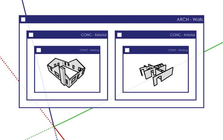
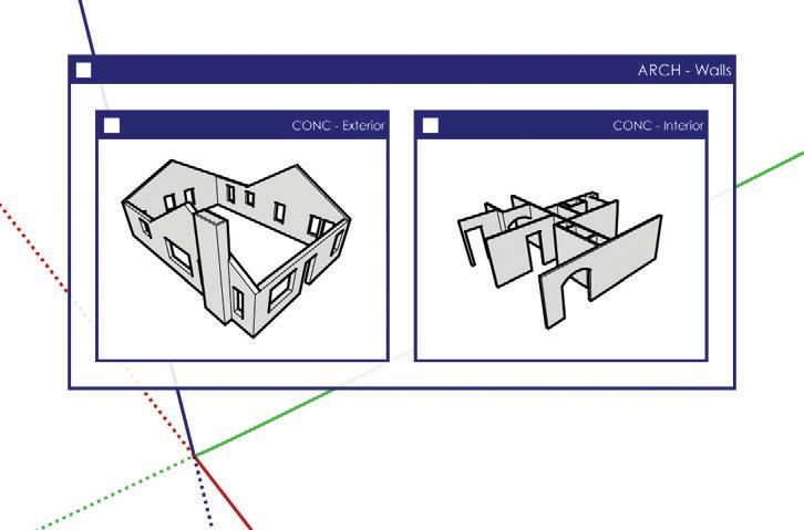
7. Double-click into the interior walls. Select all of the interior walls, right-click on the selection, and choose Make Group. Assign the group to the CONC – Existing layer, as shown in Figure 17.35.
TIP in the entity info dialog (figure 17.36), name groups by the layer on which they reside. This way the outliner will show an easy-to-navigate model structure.
Adding Detail
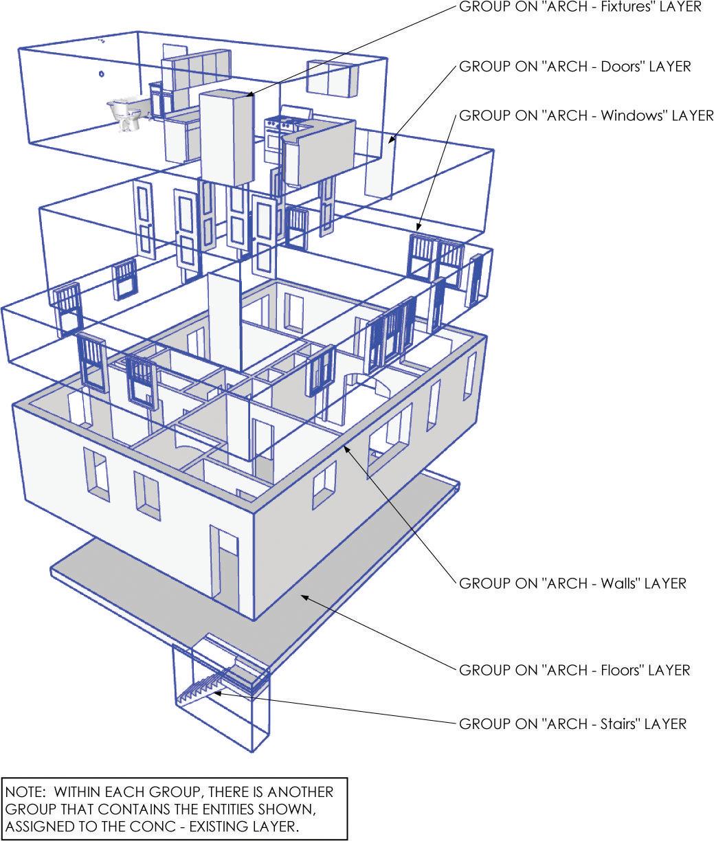
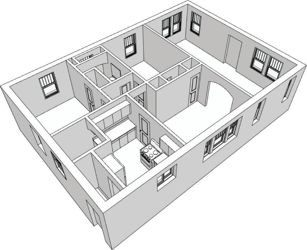
Now you are ready to add the doors, windows, fixtures, floors, and stairs using the same organization techniques, as shown in Figure 17.37. The components shown are available in the chapter files you downloaded earlier from www.suexch.com/TSWFA . To complete your existing conditions model, follow these steps:
1. Click on the File drop-down and choose Import. Make sure that the Files of Type drop-down is set to SketchUp Models (*.skp).
2. Navigate to your class files folder for this chapter and select the Fixtures.skp component. Click on the Open button to finish the import.
3. Assign the ARCH - Fixtures layer to the Fixtures.skp component.
4. Continue to insert components and apply the model organization and layering strategies shown in Figure 17.36.
TIP completely finish the as-built 3D model before you move on to the design phases. To move forward immediately, you could use the completed model from your chapter files.
Working W i T h eX i ST ing c AD Dr AW ing S
If you already have DWGs, you might not need to go out and take field notes at the site. You can simply import the .dwg files and trace over them using the same techniques and model organization you would use to trace an image of your field notes. The only difference would be that you have points to snap to rather than handwritten dimensions. Here are a few tips that will help you when you’re working with someone else’s CAD drawings:
☑ Don’t always trust someone else’s CAD work. Use the CAD cleanup scripts (available at www.smustard.com) in SketchUp, or better yet open the DWGs in your CAD program and run Flatten, Overkill, and Purge commands.
☑ In SketchUp, extrude the plan horizontally rather than trying to fill in the plan and extrude vertically.
☑ When you use the File c Import dialog, be sure to set Files of Type to .dwg
☑ Group the CAD drawing, add to the CONC – Background layer, and lock just as you did with the field notes.
c h APT er Poin TS
☑ When you’re recording dimensions, develop a system and stick to it.
☑ It is absolutely critical that you complete the accurate and organized as-built 3D model before you move on to the design phases.
☑ Download the BIC_Field Note – Letter Landscape.layout template at www.suexch.com and save to your RESOURCES/TEMPLATES folder. This template is set up with spaces for the critical information that you will typically record when you are completing as-built drawings.
Chapter 17: Site Analysis: Documenting an Existing Building


