
20 minute read
Dr AW ing Tool S


Use the Drawing tools to add geometry, symbols, annotations, title blocks, and decorations to your LayOut presentation. Each of the Drawing tools has additional features and options buried within it. Pay special attention to the modifier keys and specific processes required to effectively use all of the functions of the tools in LayOut.
Default Settings
Advertisement
When you activate any of the Drawing tools, the Drawing tool’s default settings are displayed in the Shape Style Inspector. By adjusting the properties in the Shape Style Inspector, you can change the default settings for any tool that draws lines and fills. Test the new default properties of the Drawing tools by switching to the Text tool, and then go back to any Drawing tool. You will see the settings switch back when you change tools.
All of the Drawing tools share the same default settings. For instance, if you change the default fill for the Rectangle tool, this fill will also apply to circles, lines, and polygons. Use the Pick Style tool to set the default settings for any tool. Just follow these steps:
1. Activate any Drawing tool.
2. Hover on a scrapbook and click to match the current tool’s default settings to the selected scrapbook’s settings. (See Chapter 13, “LayOut Collections,” for more information on using scrapbooks as time-saving palettes.)
3. To match an entity in the presentation area, press the S key, which is the default shortcut for the Pick Style tool.
4. Click on an entity to match the current tool’s Inspector settings to the entity that you sampled. The entity can be in the presentation space or in a scrapbook.
TIP A tool's default settings are some of those “buried” features in layout. it may not be quite clear how to use the default settings when you first attempt to use them. Patiently studying and practicing so you can fully understand how the default settings operate will save you a tremendous amount of time in the future.
Lines
Use the Line tools to create straight lines, curved lines, and freehand lines. Generating lines is a key component of drawing, and there is no exception in LayOut. The Line tools will help you create annotations, title blocks, schedule grids, tables, ground lines, details, and many other entities. Take a moment to explore all of the methods for drawing different types of lines.
Straight Lines
The simplest type of line to create is a straight line (Figure 12.2).
1. Activate the Line tool and set the stroke width to 1. Turn on the Fill and set the color to Gray. Click once in the presentation area to start.
2. Move your cursor to the right along the red axis, and click again to finish the segment.
3. Move your cursor up on the green axis. Note that the Line tool has Fill properties. This time, let go of the mouse and type a precise dimension, such as 4, then press Enter.
4. Move your cursor back to the left along the red axis. Note that there is an inference engine. To finish the line segment, click where the inference line meets the active line.
5. Move your cursor back down on the green axis, and click on the starting point to finish.
TIP Press the esc key at any time to cancel the current line segment. This will also cancel just about any command in layout.
Once a segment is finished, you can click on an endpoint with the Line tool to continue the segment. You will see the previous line segments light up blue, indicating that you are continuing that segment. Follow the previous steps to continue the straight line segment.
TIP The inference engine in layout allows you to snap to and encourage inferences from endpoints, midpoints, and edges. it is very similar to the inference engine in SketchUp.
Curved Line
You aren’t limited to straight lines. Using the Line tool, you can also create curves (Figure 12.3).
1. Click and drag away from the starting point to define the tangent line.
2. Release the cursor to set the curve’s tangent line relative to the starting point.
3. Double-click to finish the line segment.
Instead of double-clicking to finish the line, click and drag again to continue the curved line segment.
Click and drag on an endpoint of a completed line to continue a curved line segment. The existing line segment will light up blue, indicating that you are continuing that segment.
TIP To add a straight line segment to a curved line, single-click to finish the curved line segment, then continue to single click to add straight lines. To add a curved line segment to a straight line, you can click and drag to finish the straight line segment and add a curved line segment.
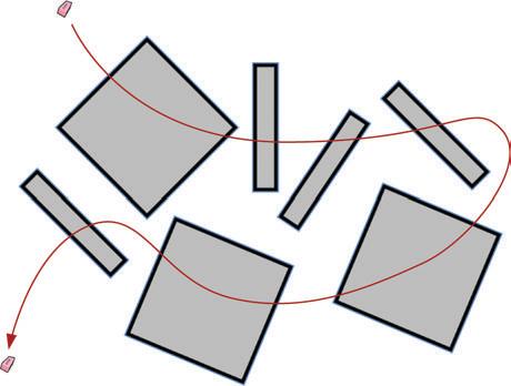
Freehand Tool
Use the Freehand tool to create sketchy, loose, and organic forms (Figure 12.4). This tool is ideal for complementing drawings, tracing topography, creating sketchy annotations, and creating unique geometry.
1. Activate the Freehand tool. Click and drag to draw a loose and sketchy line.
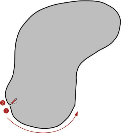
2. Release the click to finish the line.
Click and drag on an endpoint to continue the freehand line segment. The previous line segments will light up blue, indicating that you are continuing that segment.

Rectangles
LayOut’s Rectangle tools enable you to draw rectangles and squares that are always on axis and in line with the paper (Figure 12.5). In addition to a traditional rectangle, LayOut has several types of rectangles: lozenged, bulged, and rounded. Each type has its own tool icon and each operates as described here.
To draw a rectangle, follow these steps:
1. Activate the Rectangle tool. Click once in the presentation area to start the rectangle.
2. Move your cursor away from the starting point to suggest a direction. Click once to loosely define the dimensions of the rectangle.
3. At this point, you can enter a precise dimension, such as 3,5 , then press Enter. The other types of rectangles function exactly the same way (Figure 12.6).
Figure 12.6 Other types of Rectangle tools
A rounded rectangle has radiused corners. Activate the Rounded Rectangle tool, or the Rectangle tool, and then press the Up and Down arrow keys to change the radius. To enter a precise radius, type in the desired radius followed with an “r,”—for example, type 1/2r, then press Enter. This will set the corners to be 1/2 g radius.
A lozenged rectangle has half circles at the long ends of the rectangle, so a square would actually appear as a circle. Ultimately, the Lozenged Rectangle tool creates a pill shape.

A bulged rectangle has arcs at the left and right side of the rectangle. Use the Up and Down arrow keys to adjust the bulge of the arcs. After you adjust the bulge, you can enter precise dimensions by typing a value and then pressing the Enter key.
There are also several modifier keys that apply to all types of rectangles. Hold down the Shift key to constrain any rectangle to a square. Hold down the Ctrl key (Option on Mac) to create the rectangle about the center point. Use the Up and Down arrow keys to adjust the rounded corners, or lozenged and bulged sides.
TIP layout’s Measurements box is just like SketchUp’s. The Measurements box is always waiting for your input and constantly switches the value, depending on which tool is active and the input layout needs to operate effectively.
Arcs
There are several methods for drawing an arc in LayOut. The one you use will depend on your personal preference and previous experience with other drafting programs. The most familiar method probably will be the 2-Point Arc tool because it is the one most similar to the Arc tool in SketchUp. Take a moment to explore all of the tools for drawing arcs.
Arc Tool
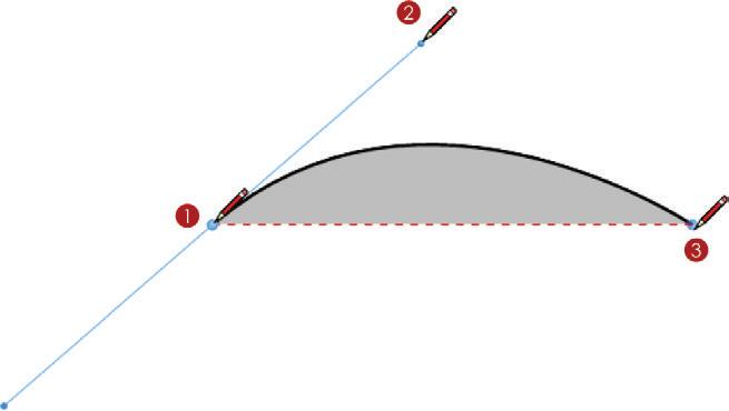
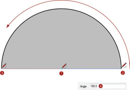
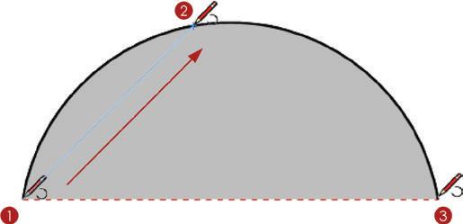
Using the Arc tool, you can create the outside of a pie chart with ease (Figure 12.7).
To do that, follow these steps:
1. Activate the Arc tool. Click once in the presentation area to define the center point.
2. Move your cursor to the right along the red axis to suggest a direction. Click again to define the start point of the arc.
3. Move your cursor away from the start point and click once more to loosely define the endpoint of the arc.
4. At this point, you can let go of the mouse and type a precise angle, such as 180, then press Enter.
2-Point Arc Tool
The most familiar arc tool is strikingly similar to the Arc tool in SketchUp (Figure 12.8).
To create an arc with the 2-Point Arc tool, follow these steps:
1. Activate the 2-Point Arc tool. Click once in the presentation area to define the start point. Move your cursor away from the center point to suggest a direction.
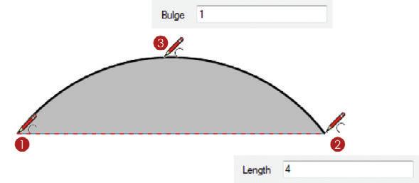
2. Click again to define the endpoint of the arc, or enter a precise distance and press Enter.
3. Move your cursor away from the endpoint and click once more to loosely define the bulge of the arc, or type a precise length, such as 3 , then press Enter.
3-Point Arc Tool
Using the 3-Point Arc tool, you can draw arcs about a pivot point (Figure 12.9). To do that, follow these steps:
1. Activate the 3-Point Arc tool. Click once in the presentation area to define the start point.
2. Move your cursor away from the start point to suggest a direction and click again to define the pivot point of the arc.
3. Move your cursor away from the pivot point and click once more to define the length of the arc.
Pie Tool
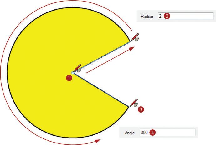
With the Pie tool, you can fill in pie charts and recreate iconic video game characters with ease (Figure 12.10).
Just follow these steps:
1. Activate the Pie tool. Click once in the presentation area to define the center point of the arc.
2. Move your cursor away from the center point, let go of the mouse, and type a precise radius such as 2 , then press Enter.
3. Move your cursor away from the start point; you can move in either direction, clockwise or counterclockwise.
4. Either click once more to loosely define the endpoint of the arc, or let go of the mouse and type a precise angle such as 300 , then press Enter.
Circles
Circles, ellipses, and polygons are all created the same way. Unlike SketchUp, there are true vector circles in LayOut, so there is no need to enter the number of sides.
Circle Tool
Use the Circle tool to draw circles (Figure 12.11).
Just follow these steps:
1. Activate the Circle tool. Click once to define the center point of the circle.
2. Move your cursor away from the center point to define the radius and click to loosely define the radius of the circle.
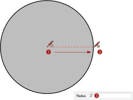
3. At this point, you can type a precise radius, such as 2 , then press Enter.
Ellipse Tool
The Ellipse tool is a variation of the Circle tool that creates ellipses (Figure 12.12). This tool operates very much like the Rectangle tool. You can also create ellipses by drawing a circle, and then using the Select tool and Scale grips to distort it.
To create an ellipse, follow these steps:
1. Activate the Ellipse tool. Click once to define the start point of the ellipse.
2. Move your cursor away from the start point and click to loosely define the dimensions of the ellipse.

3. At this point you can type the precise dimensions, such as 3,2 , then press Enter.
The Ellipse tool also has modifier keys. Hold down the Shift key while creating an ellipse to constrain it to a circle. Hold down the Ctrl key (Option on Mac) to create the ellipse about a center point.
Polygon Tool
The Polygon tool creates geometric shapes with a defined number of sides (Figure 12.13).
1. Activate the Polygon tool. Upon activating the Polygon tool, immediately enter the desired number of sides and press Enter—for example, type 5s , then press Enter.
2. Click once to define the center point of the polygon.

3. Move your cursor away from the center point and click to loosely define the radius of the polygon.
4. At this point, you can type a precise radius, such as 2 , then press Enter.
The Polygon tool also has modifier keys. Hold down the Shift key to lock the sides of the polygon to an axis. Hold down the Ctrl key (Option on Mac) to create a distorted polygon, similar to what you would create with the Ellipse tool.
Anno TAT ion Tool S
Annotation tools give you the ability to explain the graphics in your 2D presentation. Add captions, leader text, and dimensions to provide another level of information.
Default Settings
When you activate any of the Annotation tools, the default settings will appear in the corresponding Inspectors. The Text tool, Label tool, and Dimension tool have default settings in the Text Style Inspector and the Shape Style Inspector. In addition to these Inspectors, the Dimension tool has default settings in the Dimension Style Inspector. You can change the default settings manually by going through each setting in the Text Style, Shape Style, and Dimension Style Inspectors while the corresponding tools are active.
Unlike the Drawing tools, each of the Annotation tools has its own independent default settings. For example, if you change the default font for the Text tool, the text displayed when you create labels or dimensions will not be affected.
Use the Pick Style tool to set the default settings for any tool. Just follow these steps:
1. Activate any Annotation tool.
2. To match the current tool’s default settings to a specific scrapbook, hover over the scrapbook and click it. (See Chapter 13 for more information about how scrapbooks can be used as time-saving palettes.)
3. To match an entity in the presentation area, tap the S key. This is the default shortcut for the Pick Style tool.
4. Click on an entity to match the current tool’s Inspector settings to the entity that you sampled. The entity can be in the presentation space or in a scrapbook.
Text Tool
LayOut has two types of text: bounded and unbounded (Figure 12.14). Bounded text is a constrained text window. As the text reaches the border, it will automatically drop the text to the next line if a word will not fit. Unbounded text will just keep going across the page indefinitely as you type, with no boundary or end.
Typically, unbounded text is used for drawing titles, page numbers, and short bursts of text. Bounded text is better suited for larger amounts of text, such as project descriptions and notes.
To create unbounded text, follow these steps:
1. Activate the Text tool. Click once to create an unbounded Text window.
2. Enter the desired text in the text box. It will continue across the page with no boundaries.
3. To finish, click outside the text box or press the Esc key.
4. Using the Select tool, double-click on the text to edit it.
TIP When a bounded text box is resized, the bounded text is changed to unbounded. Any text can be changed back and forth from bounded to unbounded. right-click on the text and choose Make Unbounded or Make Bounded, depending on the setting you need.
To create bounded text, follow these steps:
1. Using the Text tool, click and drag to start the Text window (Figure 12.15).
Figure 12.15 When you use the Text tool, the direction in which you click and drag assigns the justification and anchoring of the Text window.

2. Move your cursor away from the start point and release it to define the boundaries of the Text window.
3. Enter the desired text. As the words you type reach the boundary, they will drop to the next line.
4. To finish, click outside the text box or press the Esc key.
5. Using the Select tool, double-click on text to edit it.
TIP you will see a red arrow on the text box when it is not big enough. you can manually resize the text box or right-click on the text and choose Size to fit to automatically enlarge the text box to fit the text.
Text Properties
The Format tab within the Text Style Inspector is where you can change text properties. While a text box is selected, you can adjust the font family, typeface, type size, and color. You can justify the text to the left, right, or center. You can also anchor the text to the top, bottom, or center of the Text window.
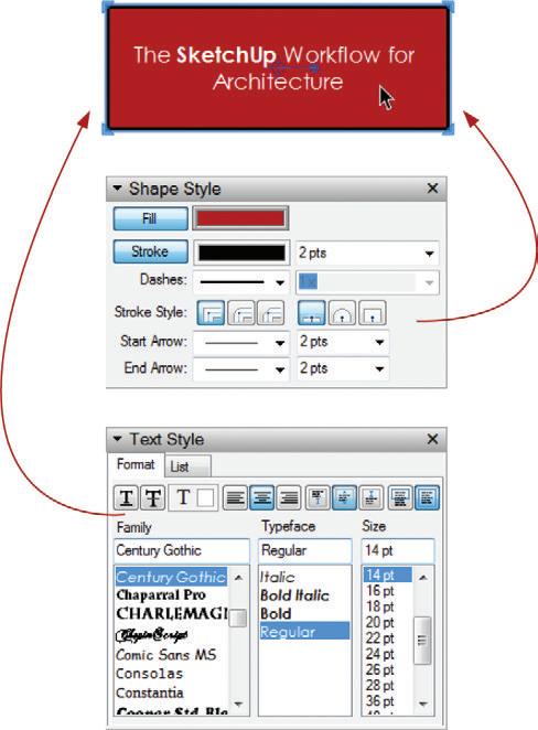
All types of text can take on any property assigned in the Shape Style Inspector (Figure 12.16). You can further modify the selected text’s appearance by assigning a fill and stroke in the Shape Style Inspector.
label Tool
The Label tool adds a leader line and attaches text to it (Figure 12.17). Keep in mind that even though this tool creates a “label,” there is no entity defined as a label in LayOut. The Label tool creates two simple entities at the same time, a piece of unbounded text and a line—each with its own Shape Style properties.
To create a leader line with text, follow these steps:
1. Activate the Label tool. Click once to place the arrow for the leader text.
2. Move your cursor away from the arrow and click again to place the text.
3. Enter the desired text.
4. To finish, click outside the text box or press the Esc key.
TIP The label tool creates straight leader lines, but those lines can be modified into curved leaders, too. Using the Select tool, double-click on a line to edit the line’s points. holding the ctrl key (option on Mac), click and drag on an endpoint to curve the line. See the “Select Tool” section, later in this chapter, for more information about editing lines.
Dimension Tools
Add dimensions to call out lengths and angles and further explain a design. Keep in mind that the default settings for dimensions are in several Inspectors; Shape Style, Dimensions Style, and Text Style. In LayOut you can create two types of dimensions: Linear (Figure 12.18) and Angular (Figure 12.19).


To add linear dimensions to a presentation, follow these steps:
1. Activate the Linear Dimension tool. Click once to define the start point of the dimension.
2. Move your cursor to another point and click again to define the endpoint of the dimension.
3. Move your cursor away from the start and endpoints of the dimension line. Click to place the dimension.
To add angular dimensions to a presentation, follow these steps:
1. Activate the Angular Dimension tool. To define the first point of the first leg of the angle, click on the first line that you want to dimension.
2. Click again on the same line to finish defining the first leg.
3. To define the first point of the second leg of the angle, click on the second line that you want to dimension.
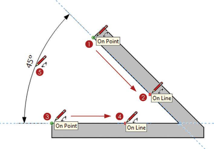
4. Click again on the same line to finish defining the second leg.
5. Move your cursor to adjust the arrows, and then click to position the angular dimension text.
Dimension Properties
Dimensions in LayOut utilize settings from several Inspectors: Shape Style, Text Style, and Dimensions (Figure 12.20). Select a dimension to see all of its properties in the Inspectors.
Editing Dimensions
Once a dimension has been created, it can be modified. Using the Select tool, double-click on a dimension to edit the dimension (Figure 12.21).

Once in dimension edit mode, follow these steps:
1. Click and drag on the text to reposition.
2. Triple-click on the text to change the shown dimension. Although it is discouraged, you can change the text displayed to force a dimension. To revert back to the automatically measured text, erase all of the forced text and press the Escape key.
3. Click and drag on the extent points to change the distance between the object being measured and the dimension line. This is called the offset.
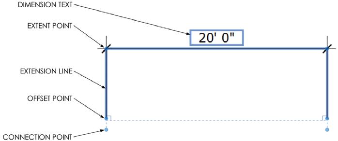
4. To change the length of an extension line, click and drag on an offset point.
5. Click and drag on a connection point to change the points being measured, and in turn length of the dimension.
TIP Angular dimensions have a very similar edit mode.
Mo D ific AT ion Tool S
The Modification tools are used to change geometry that is already created. You can use them to move, rotate, copy, split, or join existing geometry to create new complex shapes.
Select Tool
Because it is the most frequently used tool, a safe and helpful habit is to always default to the Select tool. The default keyboard shortcut for the Select tool is the spacebar. The Select tool does much more than just select entities; it allows you to move, rotate, copy, and edit geometry.
Selecting
The Select tool is used to set up many other operations within LayOut. Because it is so important, take the time to become proficient at using it to select entities. Practice these steps:

☑ Single-click on any entity in LayOut to select it. The selected entity’s properties will be displayed in the relevant Inspectors.
☑ Hold down the Shift key to add to, subtract from, or inverse a selection.
☑ Click and drag to select entities with a Selection window (Figure 12.22).
Moving/Copying
Use the Select tool to move and copy entities within LayOut. To do that, follow these steps:
1. Select an entity or select multiple entities.
2. Click and drag on the selection to move the entities all at once.
3. Release the mouse button to finish the move.
4. Immediately type a precise distance, such as 5 , then press Enter.
The Move feature of the Select tool also has modifier keys. Use them as follows:
☑ Click and drag while holding down the Shift key to lock an axis.
☑ Click and drag while holding down the Ctrl key (Option on Mac) to make a copy.
☑ To encourage inferences and create meaningful relationships between LayOut entities, hover endpoints, midpoints, and lines of the entity you are moving on other endpoints, midpoints, and lines of entities in your presentation.
TIP Use the arrow keys on your keyboard to nudge a selected entity 1/64 g in the desired direction. hold down the Shift key while nudging to move an entity 1/4 g in the desired direction.
Precise Moving/Copying
The Precise Move grip allows you to move entities in LayOut with complete control. Use a precise move to align drawings, annotations, title blocks, and geometry to make more accurate and visually appealing presentations (Figure 12.23).
Just follow these steps:
1. Select an entity and notice that the precise move grip appears in the middle of the selection.
2. Click and drag on the left side of the Precise Move grip to pick it up. You can encourage inferences from the Precise Move grip before placing it.
3. Release on a meaningful point to put it down.
4. Click and drag anywhere on the selection to move it.
5. Allow the Precise Move grip to snap to an inference on another entity. You can also encourage inferences from the Precise Move grip.
Figure 12.23 A precise move is when you move an entity from one specific point to another specific point.
TIP hold the ctrl key (option on Mac) and Shift key down while performing a precise move to create a copy along an axis.

Rotating/Copying
LayOut doesn’t have a dedicated Rotate tool. However, you can accomplish any rotation you’ll need with the Precise Move grip, which is the center of any rotation (Figure 12.24).
Follow these steps:
1. Select an entity and notice that the precise move grip appears in the middle of the selection.
2. Click and drag on the left side of the Precise Move grip to pick it up. You can encourage inferences from the Precise Move grip before placing it.
3. Release on a meaningful center point of rotation to put it down.

4. Click and drag on the right side of the Precise Move grip to start the rotation.
5. Release the mouse button to finish.
6. Now you can enter a precise degree of rotation, type -45 , then press Enter.
TIP hold the ctrl key (option on Mac) down while rotating any entity to create a copy.
Scaling
Use the Select tool to scale and distort entities in LayOut (Figure 12.25).
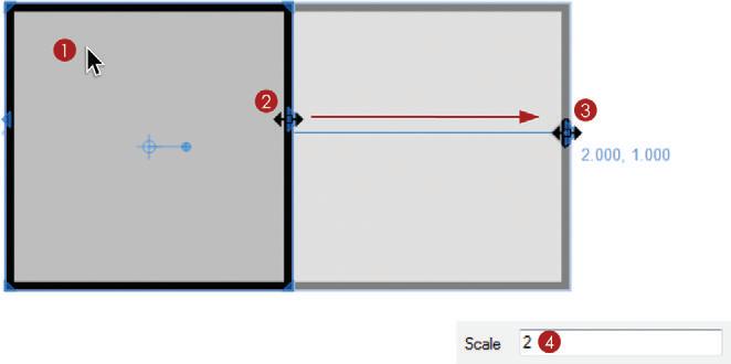
1. Select an entity or multiple entities.
2. Click and drag on the Perimeter grips to distort or scale the selection.
3. Move your cursor away from the Scale grip and release it to loosely set the new scale.
4. Now you can enter a precise scale value, type 2 , then press Enter.
TIP There’s not much space for your cursor between the Move and Scale features. Be sure to watch the cursor icon closely to determine which feature you are using.
TIP hold the control key (option on Mac) down while scaling any entity to create a copy.
When you are scaling in LayOut, keeps these points in mind:
☑ Hold down the Ctrl key (Option on Mac) to make a copy while scaling.
☑ Hold down the Shift key to constrain the selection’s proportions while scaling.
☑ To mirror a selection, scale to –1, or right-click on an entity or selection and choose Flip c Top to Bottom or Flip c Left to Right.
Line Editing
Use the Select tool to edit lines and shapes in LayOut. The methods discussed here apply to all the geometry in LayOut, including lines, rectangles, circles, arcs, polygons, etc. There are several methods for modifying geometry using the Select tool. Double-click on the line or entity and then:
☑ Click and drag on a point to reposition it, ultimately modifying the geometry.
☑ Hold the Ctrl key (Option on Mac) and click along the line to add control points.
☑ Drag a control point onto another control point to delete it.
☑ Hold the Ctrl key (Option on Mac) and click and drag control points to curve the line. A curve can be created from any point along a line.
☑ Click and drag the tangent control points of a curve back to the control point to remove the curve, ultimately making the line straight.
eraser Tool
Use the Eraser tool to delete entities from a presentation (Figure 12.26). Follow these steps:
1. Click once on an entity to erase it.
2. Alternatively, hold down the mouse button and drag the cursor over the entities. All entities will be erased when the mouse button is released.
Style Tool
The Style tool is very similar to a “match properties” tool in other programs
(Figure 12.27). To use it, sample all of the properties from one entity and in one click apply them to another entity. The style tool can sample from and apply to any combination of shapes, edges, viewports, images, text, etc.
Follow these steps:
1. Activate the Style tool. To sample an entity’s style, click on it in a scrapbook or in the document presentation area.
2. Click on the entities to which you want to apply the sampled properties.

TIP Tap the escape key to start over, or hold down the ctrl key (option on Mac) to sample another entity.
Split Tool
The Split tool divides line segments and also creates breaks between overlapping shapes (Figure 12.28).

To use the Split tool to break LayOut geometry down into simpler forms, follow these steps:
1. Activate the Split tool. Click on an intersection between the two shapes.
2. Click on another intersection between the two shapes. Use the Select tool to examine the results.
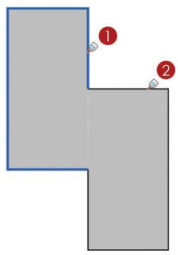
Join Tool
The Join tool glues together lines that share a vertex (Figure 12.29). It is used to combine shapes to create more complex geometry.
To use it, follow these steps:
1. Activate the Join tool. Click on the first entity that you would like to join.
2. Click on the next entity that you would like to join. Use the Select tool to examine the results.
c h APT er Poin TS
☑ Each group of tools has a specific function. Before you perform an operation, make a plan and think it through. Ask yourself, what is the fastest way to complete the task?
☑ Using a combination of the Drawing and Modification tools, you can create any shape, precise or sketchy, in LayOut.
☑ Instead of sorting through several dialogs, use the Pick Style tool to set the defaults for your tools.
☑ When you execute a command, most of the LayOut tools allow you to enter precise dimensions during the command. Some of the LayOut tools allow you to also modify the precise dimensions after you execute the command, until another command is started.
☑ Unlike SketchUp, LayOut is mostly a click-and-drag program.


