OIL-FILM INTERFEROMETRY
Quantification of aerodynamic performance of riveted and smooth airfoil

SHALOM MASANGO, BRENDYN GOODWIN, RYAN SCHAEFER
ADVISOR: DR. DURGESH, MENTOR: ANAS NAWAFLEH
Acknowledgement: Rodrigo Padilla; wind tunnel setup, testing, and post-processing.
Problem Statement
Daher horizontal tail uses type 4 fasteners which patterned roughness may affect the aerodynamic performance of the horizontal tail.
Value Proposition
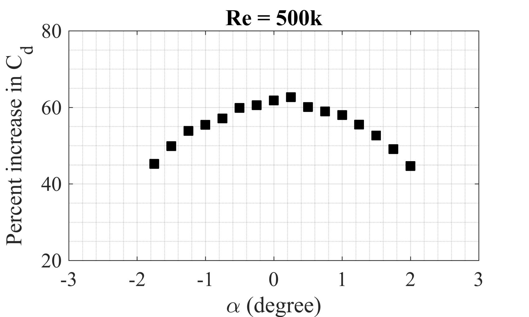
Quantify the increase in drag forces of a horizontal stabilizer with riveted and smooth surfaces.
Theory
Reynolds number (����= ���� �� ) is a quantity used to predict the fluid flow on the airfoil’s surface. The airfoil chord length (��) and airspeed (��) are changed to maintain similar aerodynamic surface conditions.
Wind Tunnel Setup
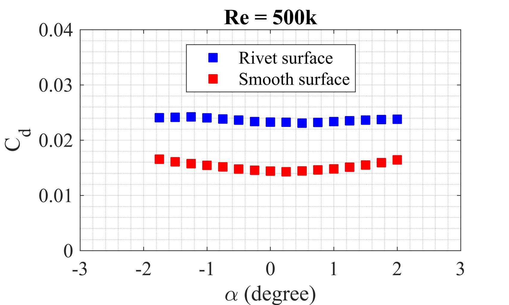
Measured drag and lift forces for α= ±5.08 degrees at Re = 3 × 10⁵ , α= ±5.08 degrees at Re = 4 × 10⁵ , and α= ±2.52 degrees at Re = 5 × 10⁵ .
Results
Smooth airfoil
Fixture rod
Fixture adapter (top)
Electronic load cell
Fixture adapter (bottom)
Stepper motor
The Oil-Film Interferometry (OFI) experiments determine the coefficient of skin friction of an airfoil in a wind tunnel. The airfoil has a line of oil applied to its leading edge, which is spread by the wind. Dark and light fringes are formed on the surface of the airfoil, which are visible through a camera and light setup. By analyzing these fringes, the coefficient of skin friction can be determined.

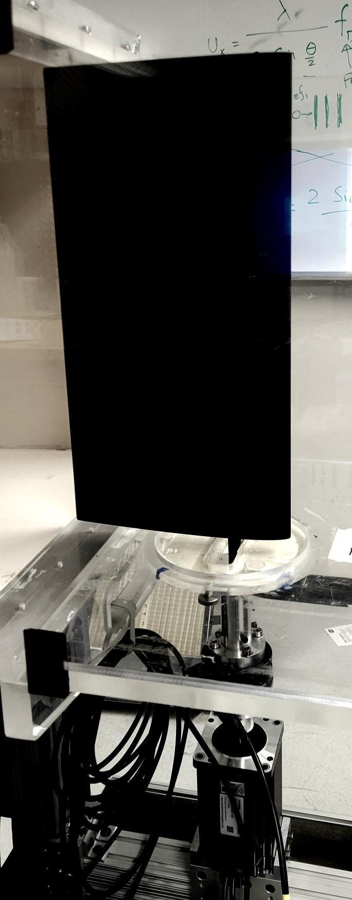
Additionally, a load cell sensor is used to measure drag and lift forces acting on the airfoil. The airfoil is mounted vertically in a wind tunnel and subjected to a constant velocity. The atmospheric pressure, windspeed, and a targeted Reynolds number are key factors used to simulate real-world conditions on the aircraft.
Airfoil Design
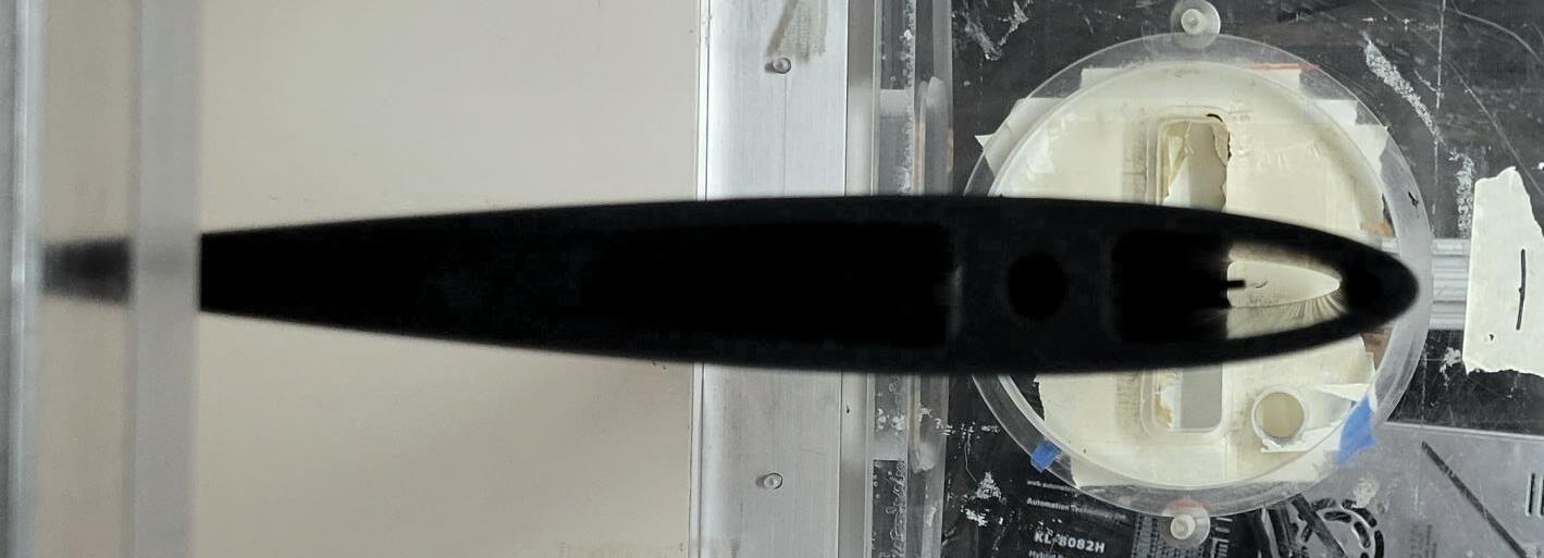
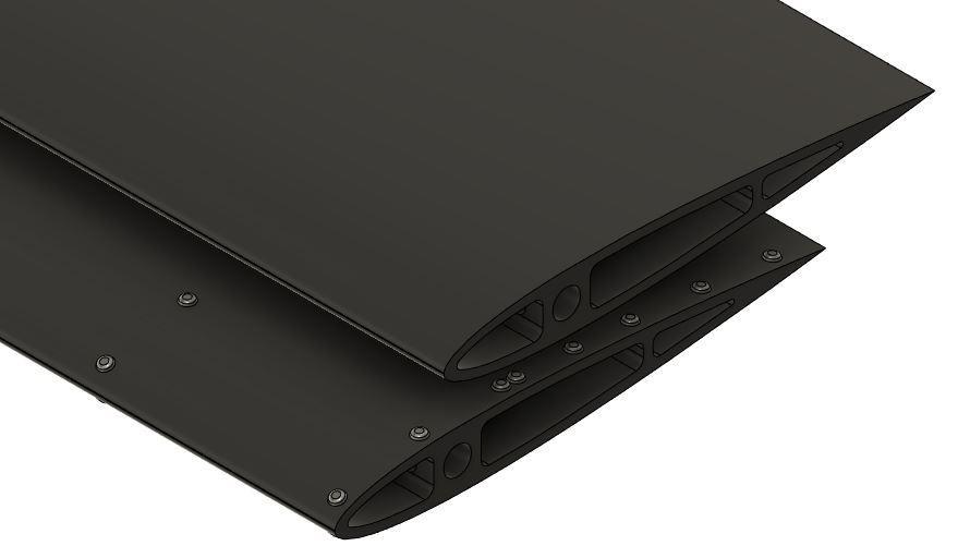
9-inch chord, 17.5-inch span, 1.08-inch thick (NACA 0012): smooth vs. type 4 universal head rivets

3D resin printed in black acrylic plastic by StrataSys direct manufacturing (~$500 per airfoil)
Conclusion & Future Work
The airfoil with type 4 universal head rivets produced more drag than the smooth airfoil.
Smooth Surface
Riveted Surface
Perform OFI experiments at different Reynolds numbers to measure skin surface shear stresses and identify cause for increase in the drag.
Design a setup to mount on Kodiak aircraft for a full-scale OFI test.
Analyze the impact on aircraft efficiency due to riveted horizontal tail airfoil.

