
3 minute read
Model Post-Processing
Geo-Magic Work Flow: Geomagic transfers the point file created from the Konica Minolta into a 3D file for user manipulation. The desired end result is a watertight mesh ready for manipulation in Rhino.
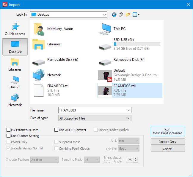
1. Menu > Insert > Import. 2. Select file from memory card and select “Run Mesh Buildup Wizard”.
Advertisement
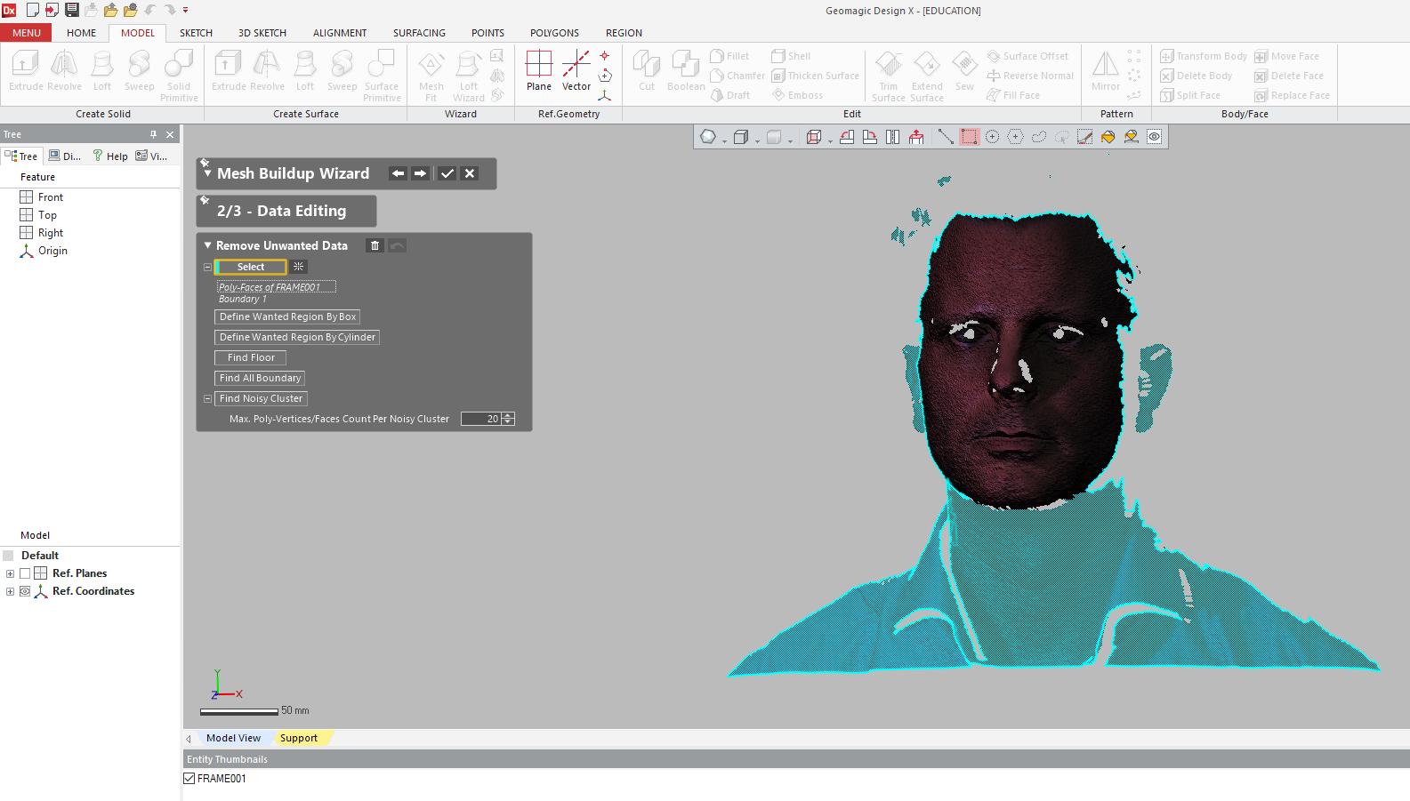
3. Highlight unwanted portions.
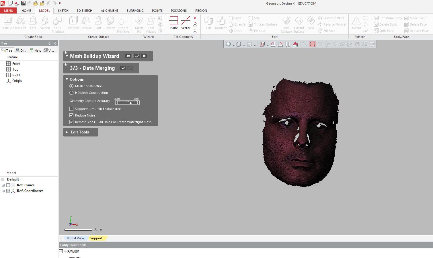
3. After deleting selected entities select options desired for mesh. Reduce Noise & Remesh And Fill All Holes To Create Watertight Mesh, must be selected.
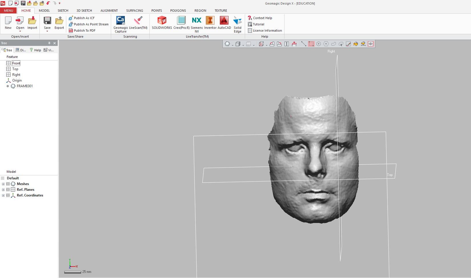
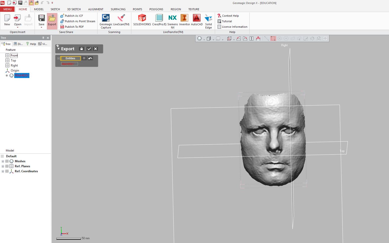
4. Select desired frame and click export from command bar.
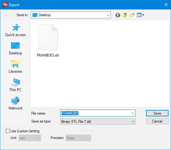
5. Export as .stl to desired location and return memory stick.
Model Post-Processing
Rhino Work Flow: Geomagic will export a watertight mesh via an .stl file. This mesh will need to be manipulated in Rhino prior to being sent to Partworks and then Shopbot for CNCing.
A ¼” double fluted wood straight bit can cut up to 1” in depth of materials. Therefore the mesh must be cut transversely into < 1” segments. The following steps display a typical workflow for preparing a mesh to be CNC-ready. Other ways are certainly possible.
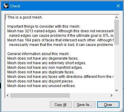
1. Import .stl file generated from Geomagic. 2. Run a check command to verify mesh is good.
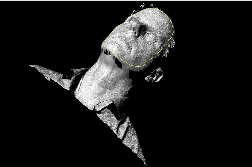
3. Establish “wanted” regions of mesh by drawing a curve around the desired profile of the object. 4. project curve onto the surface of the object.
5. splitmeshwithcurve to remove unwanted mesh from the whole.

6. Verify overall height of the object to determine the amount of mesh needed to be trimmed transversely. 7. Run smooth command until desired results are achieved.
8. Create a plane to establish lower extents and trimming plan of mesh. 9. extrude projected profile curve downwards below the previously created clipping plane. It is important to make sure extruded angle is at or greater than 90 deg. This ensures easy removal of the plastic mask from the mold.
10. Convert extruded polysurface to mesh with mesh command. 11. offset transverse lines in less than 1” intervals to establish transverse cuts. (e.g. ¾” offsets).
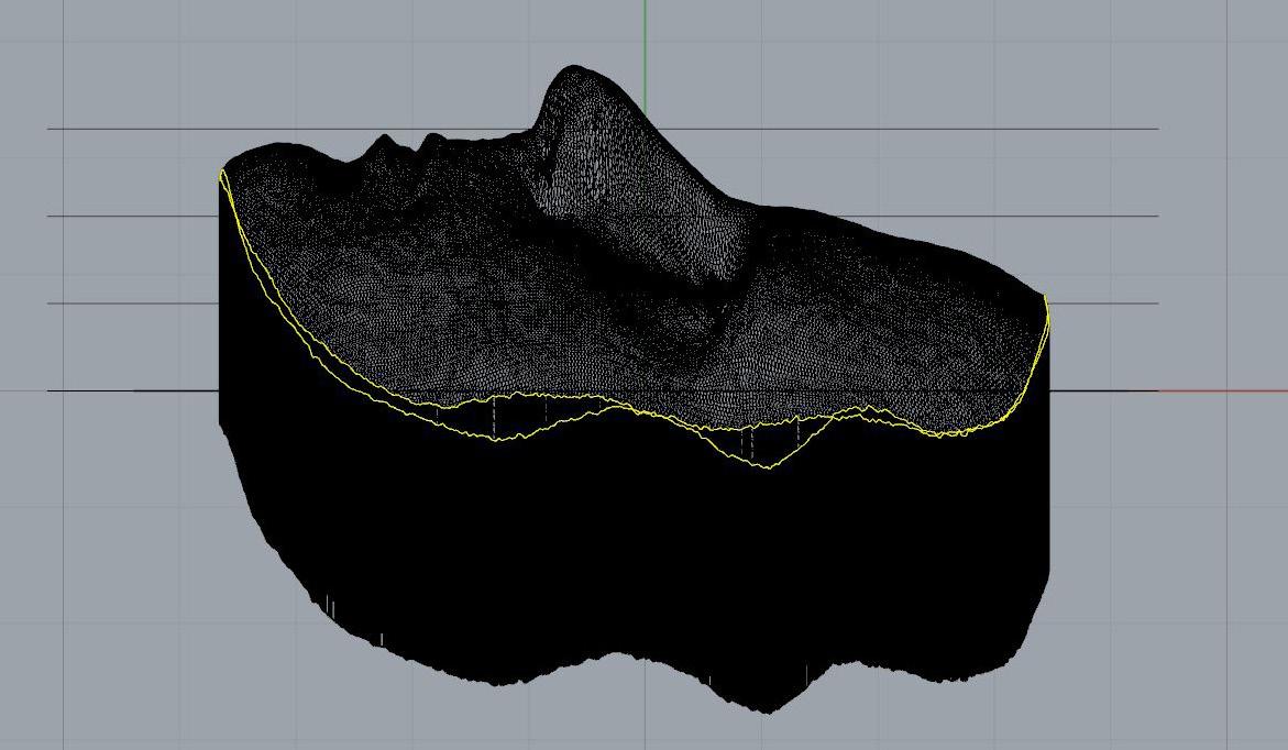
12. Project offset lines onto both the extruded mesh and original model mesh
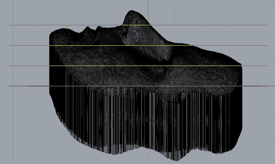
13. Join perimeter curves to form one closed polyline
14. Splitmeshwithcurve both the extruded mesh and model mesh separately. (A separate command will need to be used. Attempting to split both the extruded mesh and the model mesh together will result in an incomplete mesh).
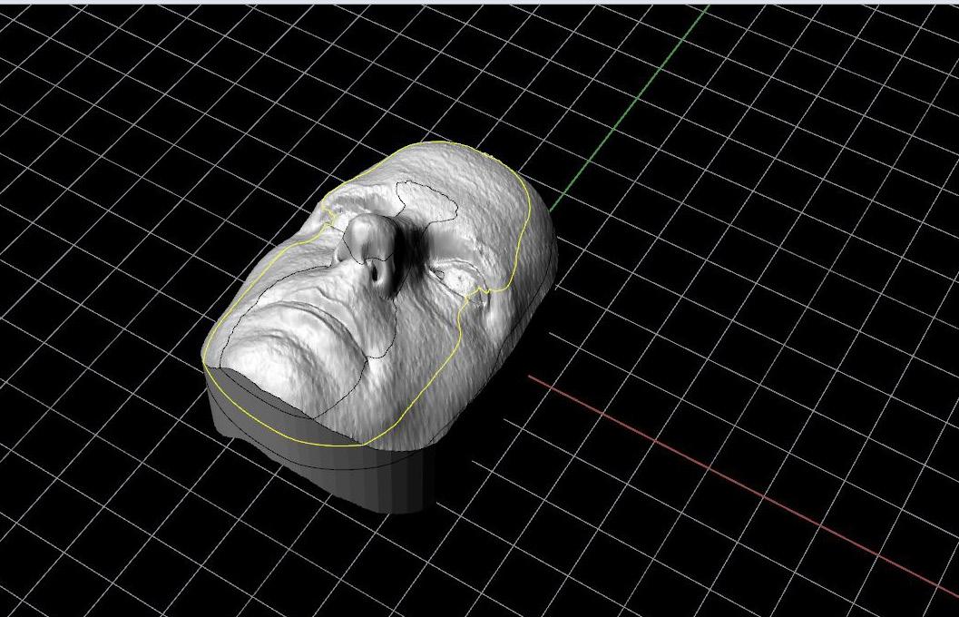
15. Repeat splitmeshwithcurve command for each respective layer until all layers have been divided into ¾” sections. 16. Copy 3D model in accordance with the number of layers (e.g. 3).
17. Delete portions of each model to create separate layers.
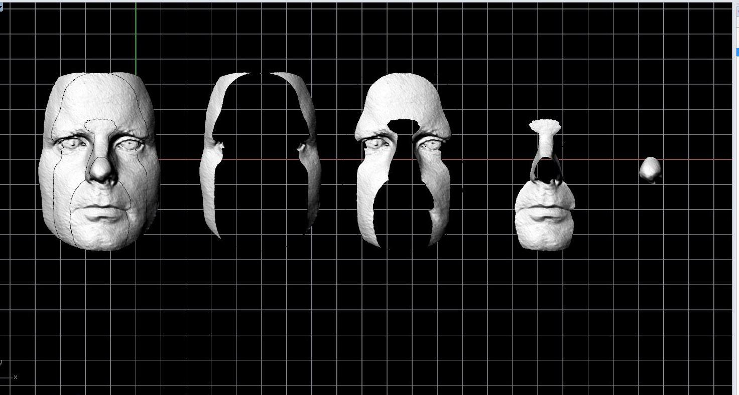
18. Using meshfromclosedpolyline close top and bottoms of each layer to create separate layers
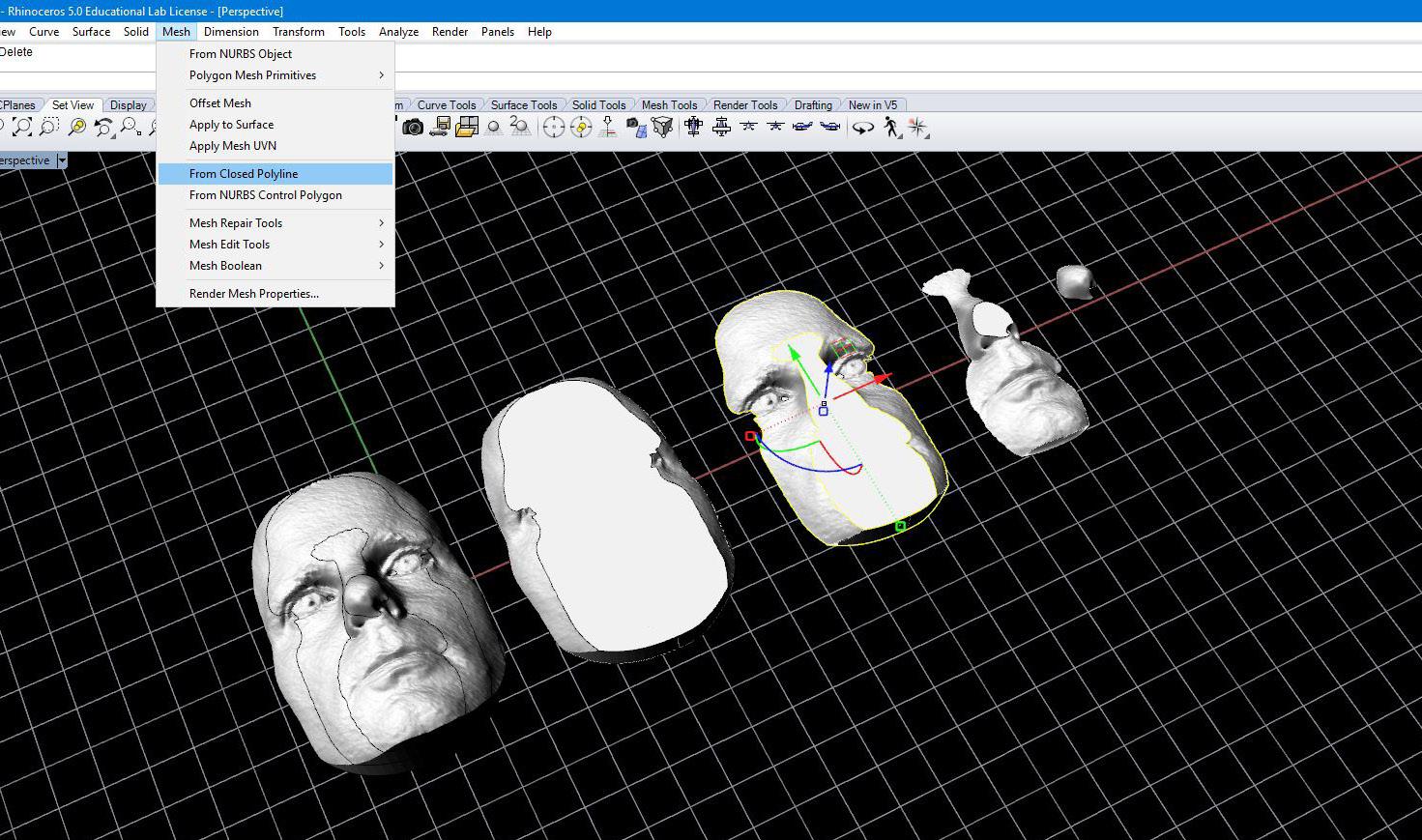
19. Join meshes for each layer together to form separate pieces.
20. Move each combined piece to ground level. This is critical when moving model into CNC software, each piece MUST be on ground level.
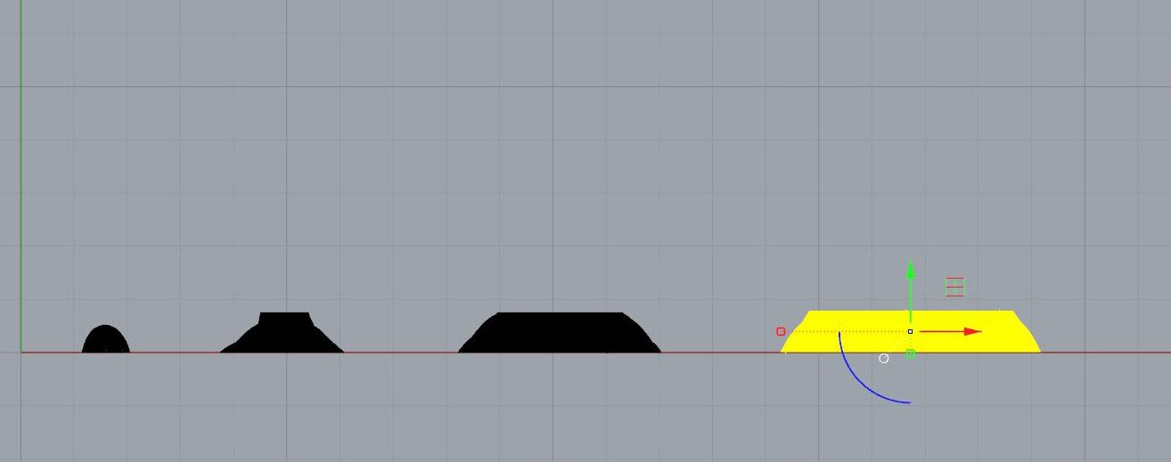
21. Check each joined mesh to ensure mesh is good. - If manifold edges exist, used extractnonmanifoldedges command. - If degenerate faces exist use culldegeneratefaces command.
22. Export as .stl file.


