11 minute read
Mumbai Trans Harbour Link


Project Overview of Package 2 Mumbai Trans Harbour Link
by Peter Curran
Advertisement
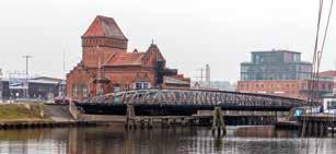
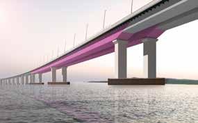
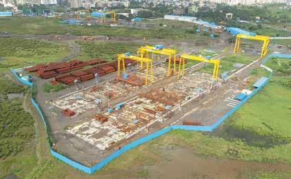
1 General View of Package 2 © Ramboll Group A/S
This presentation offers an overview of the design and construction of the new Mumbai Trans Harbour Link, with a particular focus on Package 2. It focusses on the background to the project as a whole, the need for it, and describes the challenges faced in bringing the project to fruition. The structural form adopted will be described as will some of the design and construction techniques and challenges.
1 Introduction The Mumbai Trans Harbour Link (MTHL), also known as the Sewri-Nhava Sheva Trans Harbour Link, is a proposed 21,80 km, freeway grade road bridge connecting the Indian city of Mumbai with Navi Mumbai, its satellite city. When completed, it will be the longest sea bridge in India.
The bridge will begin in Sewri, South Mumbai and cross Thane Creek north of Elephanta Island and will terminate at Chirle village, near Nhava Seva. The road will be linked to the Mumbai Pune Expressway in the east, and to the proposed Western Freeway in the west. The sea link will be a six-lane highway, which will have dual carriageway of 13,50 m width each, in addition to edge strip and crash barrier. The sea link will decongest adjoining roads, provide a vital link from the south of Mumbai to some 24.000 ha of development land in Navi Mumbai and will provide a gateway to Navi Mumbai International Airport and Mumbai-Pune Expressway. The new crossing will reduce journey lengths by some 17 km and travel time by well over an hour, more in busy periods. The whole project is estimated to cost Rupien 14.262 crore (2 billion $). The Mumbai Metropolitan Region Development Authority (MMRDA) awarded contracts for the project in November 2017; construction began in April 2018, and is scheduled to complete within four-anda-half years. The MMRDA estimates that 70.000 vehicles will use the bridge daily after it opens.
2 History The scheme has been under consideration for more than 50 years, first suggested as part of extensive traffic planning studies carried out in 1962. Latterly there were a number of failed attempts to deliver the project, with the pursuit initially being based on a private finance model.

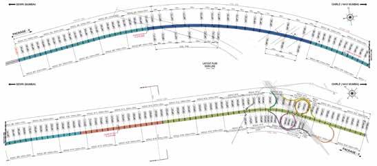
3 Layout of Package 2 © Ramboll Group A/S
3 Contract Award The MMRDA decided to scrap the PPP model for the project in August 2013, and instead execute it on a cash-contract basis. Subsequently, the Japan International Cooperation Agency (JICA) expressed interest in providing funds for the project. The project ran into a further major hurdle in April 2015, when environmental objections were raised and concerns raised that it would affect »existing mangroves as well as the flamingo population«. The project required requisite approvals as it will affect 38 ha of protected mangrove forests and 8,80 hectares of forest land on the Navi Mumbai end. The sea link´s starting point poses a threat to an estimated 20.000–30.000 lesser and greater flamingos and the mangrove habitat. Further studies were conducted and in 2017 the necessary permissions were finally achieved as was a funding arrangement with JICA. As part of the agreement between JICA and the State Government, two rescue lanes were added to the proposed plan for the crossing, and a 4 km stretch of the bridge will be constructed as a steel-only structure instead of previous plan to build a wholely concrete bridge with additional associated costs. The MMRDA invited request for qualifications (RFQ) for civil construction of the project in three received 11 pre-qualification bids each for the first and second package, and 17 bids for the third package. Packages were ultimately awarded as follows:
Stratum Maximum Thickness (m) General Description
Alluvium (Marine Clay) 21.00 Very soft to stiff, dark grey clay with varying amount of sand and silt
Granular Material 3.00 Grey, sand, silt and gravels with occasional traces of rock. Possibly underlying basalt which has been weathered to residual soil.
Basalt Unproven Very weak to strong, brownish grey to dark grey fractured rock.
4 Brief overview of the strata © Ramboll Group A/S
Package 1: Length 10,38 km spanning across Thane Creek and Sewri Inter change awarded to Larsen and Toubro and IHI Corporation in the sum of Rupien 7.637,30 crore (1,10 billion $). Package 2: Length 7,807 km spanning across Thane Creek and the Shivaji Nagar interchange awarded to Daewoo E&C and Tata Projects Limited in the sum of Rupien 5.612,61 crore (790 million $). Package 3: 3,613 km Viaducts and interchanges that connect MTHL with State Highways 52 and 54 and National Highway 4B at Chirle awarded to Larsen and Toubro in the sum of Rupien 1,013.79 crore (140 million $). Daewoo-TPL Joint Venture who won the Package-II appointed Ramboll as Designers for the Design-and-Build contract for providing detailed design services and technical support during construction stage. 4 Ground Conditions The published Geological Survey of India geological map for the area »Pune and Bombay Quadrangle, Maharashtra« (1997) shows the site to comprise Alluvium underlain by compound and simple Basalt flows in the west of the site and mainly Compound Pahoehoe Basalt flows in the east of the site. Three no. basic dykes are shown to be present in a north south orientation in the land side area. The basalt bedrock comprises varying weather grades classified by Rock Quality Designation (RDQ) and Total Core Recovery (TCR) as defined in BS 5930:1981 with RQD and TCR determined from extracted rock cores.
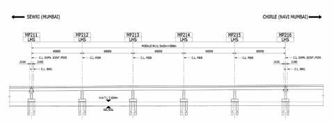
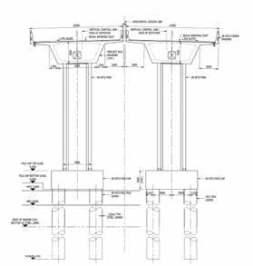
5 Typical Marine Module Elevation © Ramboll Group A/S
5 Foundation Solutions 5.1 Marine Foundations Piled foundations are utilized for marine pier locations. Piles are being installed using Reverse Circulation Drilling (RCD) method, which is one of the most efficient drilling techniques for large diameter piles in hard rock. Initial pile load tests using bi-directional load cells with a test load of 62,50 MN were carried out on sacrificial piles at two locations. The test results were used to verify the pile design. The design of the substructure is governed by seismic forces, with the exception of the larger steel spans which are governed by wind loads. The typical marine foundation consists of a four pile group with a high-level pilecap above high water level. The substructures in this area have been designed without plastic hinges to meet the Employer’s requirements for no damage below the pilecap. A non-linear analysis was utilized in the design for every pier location to minimize the reinforcement in the piles. The piles are cast within steel liners above rock level to facilitate construction.
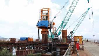
6

Marine Pilinging by Reverse Circulation Drilling © Ramboll Group A/S
7 Piling from Causeway © Ramboll Group A/S
5.2 Land Foundations For pier locations on land where rock is present at or near the surface, open (large pad) foundations were utilized. Where founding material was completely or highly weathered rock, the bearing capacity was verified by in-situ plate bearing tests organized and carried out by the Contractor.
6 Superstructure 6.1 Two Types Superstructure is of two types.
6.2 Concrete Spans – Mostly 5 x 60 m modules externally Post tensioned precast segmental superstructure monolithic over hollow piers with bearings only at expansion joint location – Minimum continuous length (without expansion joints) 200 m as per ER – Superstructure rigidly connected to piers supported on Pile foundation – Independent superstructure for each carriageway
8

Temporary Bridge Piling near Mumbai © Ramboll Group A/S
Description Segment Type A Segment Type B Segment Type C Rescue Span Segment
No. of Field Segments 2.605 93 339 15
No. of EJ Segments 74 4 12 0
Total No. of Segments 2.679 97 351 15
3.142
Segment Width [m] 14,90 14,60 10,00 8,80
Segment Depth [m] 3,50
Segment Length [m] 3,825 (Maximum) / 3,49 (Minimum)
Module No. Module 1 ~ 5 + 16L + 18R + 20L + 21R + 22R + Part of (16R + 22L) Module 17L + 18L + Part of (16R + 22L) Module 17AL + 17 R + 19 + 20R + 21L Module 7L
Radius in Plan [m] 1.000 1.000 1.000 4.200
9 Segment Details © Ramboll Group A/S
Each span of the viaduct is split into certain number of field segments and pier respectively expansion joint segment at the ends. Field segments are typically around 3,49 m to 3,825 m long will be cast using field segment casting cell. Field segments are cast successively against the previous segments such that they all fit together when assembled in sequence at actual span location. Expansion joint segments are 2,20 m long and will be cast using EJ segment casting cell. Pier segments are 2,90 m long and will be cast in place.

11 Typical Section at Marine Piers © Ramboll Group A/S
Casting cell is designed for the short line method of match casting concrete segments, whereby each completed field segment is shifted forward by one position such that next segment is cast in same place using the face of preceding segment to form the joint face. Twelve casting cells are provided for field segment casting and a single casting cell is provided for casting of the expansion Joint segment.
12 Typical Section at Steel Spans © Ramboll Group A/S

The anticipated segment cycle time is typically 2,50~3 days cycle for field segment and 6 days cycle for expansion joint segments. These cycle times are based on the condition that prefabricated rebar cages are used and three soffit forms per cell are utilized. 6.3 Steel spans Orthotropic steel box deck with spans ranging from 90 m to 180 m resting on hollow piers with piled foundations.

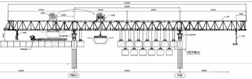
15 Layout of Overhead Gantry © Ramboll Group A/S
7 Superstructure Construction The precast segments will be constructed using an overhead gantry on a span-byspan construction method. The superstructure is designed to be continuous with the complete viaduct is split in to various number of modules. The pier segment is monolithically connected to the pier, hence pier segment is cast along with pier. Superstructure between the pier segments are precast segments which is erect by the overhead erection gantry.

16 Segment Casting © Ramboll Group A/S
Cast In situ wet joint to be provided between pier and field segments. – The segmental viaduct will be erected span by span with segments delivered behind the gantry (most of cases) on previously constructed spans or from ground beneath the span where possible. Each segment shall be lifted up by the UCB, transported near to the final location and hung to the MT, starting from the front, one by one. – Once all segments are lifted and hung under the trusses, the segments are then assembled to the full span as close as possible to its final alignment. – All precast field segments are aligned and glue match with each other and temporary stressing to be done. – All field segments are to be aligned to the final position, stitch concreting shall be done between pier and field segment. – Once the stitch concrete attains required strength, longitudinal PT tendons are installed and stressed.
8 Challenges Employers Requirements: Design comprising with many codes. Concrete decks are designed according to Indian codes, whereas the steel superstructure and bearings are designed with Japanese codes, while the substructure and expansion joints with Indian codes. Two level seismic design: Structure to be designed for both DBE and MCE Seismic events. Site spectra study was also carried out. Large diameter piles in sea, widened deck with complex geometry varying from 12,90 m to 21,50 m.
Author: Peter Curran Bsc, CEng, MICE, MIStructE Ramboll Group A/S, London, United Kingdom Client Mumbai Metropolitan Region Development Authority (MMRDA), Mumbai, India
Clients Engineer Aecom Cop., Gurgaon, India T.Y. Lin International, San Francisco, USA Dar Al-Handasah PP, Beirut, Lebanon
Designer Ramboll Group A/S, Mumbai, India
Independent Checking Engineer WS Atkins plc, Gurgaon, India
Contractor Tata Projects Ltd. and Daewoo E&C Joint Venture, Mumbai, India
Principal Subcontractor VSL India Private Ltd., Chennai, India
die neue lineare Brückenentwässerung ACO KerbDrain® Bridge –
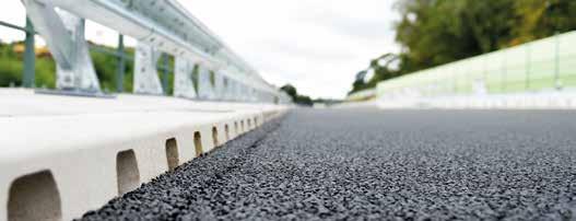
Die KerbDrain Bridge ist eine Kombination aus Entwässerungsrinne und Schrammbordstein der Kappe und steht damit für eine neue Form der linearen Brückenentwässerung. Die monolithische Hohlbordrinne bietet gestalterisch und technisch vielfältige Möglichkeiten auf der Brücke. www.aco-tiefbau.de/bridge
n Entwässerung im Bereich der Kappe n Geeignet für Neubau und Sanierung n Rückverankerung – Richtzeichnung Kap. 12 n Mit integrierter Dichtung n Klasse D 400
ACO Tiefbau Vertrieb GmbH Postfach 320, 24755 Rendsburg, Tel. 04331 354-500, www.aco-tiefbau.de