20 minute read
Light Plane Heritage


published in EAA Experimenter MARCH 1994
A Line on In-Line
by Bob W ittier EAA 1235
Engines
The term “in-line engine” is encountered so infrequently today that many aviation enthusiasts are unsure of its meaning. It refers to any engine having its cylinders arranged in a row, one behind another. Many ultralight engines fit this description. The four-cylinder engines now common in light cars are the in-line type. Decades ago, many luxury cars had in-line engines that people referred to as being of the “straight-8” type to differentiate them from the vee-8 kind. Until recently, in-line six-cylinder engines were widely used in cars.
From the pioneer days up to the 1930s, in-line engines were widely used in aircraft. At fly-ins we still see Ranger in-line engines on the noses of some Fairchilds, and inline de Havilland Gipsy Majors on Tiger Moth biplanes. In museums we can see World War I in-line engines such as the German Mercedes. While most of these had six cylinders, some had eight. These were massive, rugged, dependable engines and weighed between 600 and 800 or more pounds.
Because no other airplanes were around in 1903 for the Wright brothers to look at and duplicate by “eyeball engineering,” the two were very much on their own. By dint of much study, discussion, and original thinking, they worked out their own rules of aerodynamics in order to figure out a workable size and shape for their Flyer.
They calculated that at least eight brake horsepower would be needed to generate enough lift from the Flyer’s thin-airfoiled wings. Finding that no auto or marine engine manufacturer of 1903 could supply a single-cylinder en-
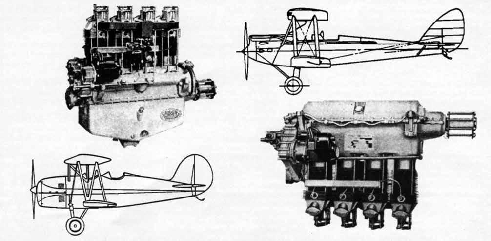
English Cirrus upright in-line engine, top left, powered many light civil aircraft such as the de Havilland Gipsy Moth, top right. High positioning of carburetor led to thick, gravity-feed fuel tank in center section. Engine heat and grease flew back onto occu pants. Poor over-the-nose visibility. Lower right, both upright and inverted Cirrus engines were made in the United States under license. Inverted Cirrus in Great Lakes biplane, lower left, made possible a much cleaner installation.
Editor’s Note: The Light Plane Heritage series in EAA’s Experimenter magazine often touched on aircraft and concepts related to vintage aircraft and their history. Since many of our members have not had the opportunity to read this series, we plan on publishing those LPH articles that would be of interest to VAA members. Enjoy!—HGF
gine of that power that weighed no more than 200 pounds, they realized they’d have to design and build their own engine.
It’s very likely that the following thought occurred to them. Perhaps an admirably simple single-cylinder engine would not be as light as might at first be assumed? To keep it and the twin chain-driven propellers turning between its widely spaced power strokes, a heavy flywheel would be needed. So they decided to build a four-cylinder engine.
It’s a surprising but mathemati- cally provable fact that if a singlecylinder engine is doubled in all of its dimensions, its power will be quadrupled but its weight will increase eightfold. But if the cylin- der and piston dimensions of the small single are used as the basis for a four-cylinder engine, while power will increase fourfold, weight will also increase only fourfold. That’s one reason why the Wrights were on firm ground in choosing to build a four-cylinder engine.
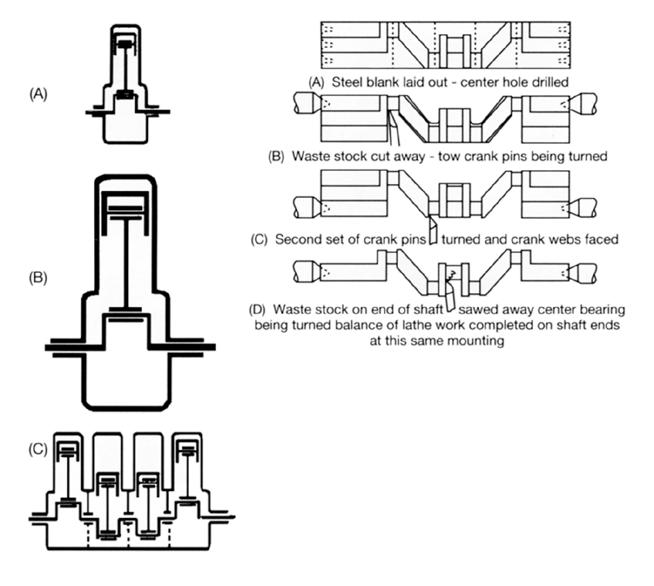
Furthermore, it is easier than many people realize to make a crank- shaft having four throws. One starts with a slab of steel of some suitable alloy and of a length, width, and thickness to suit the crankshaft. As an accompanying drawing shows, by removing selected chunks from this slab, a crankshaft blank is ob- tained that can be put into a lathe for finishing.
Both in the United States and Europe, four-cylinder in-line en- gines thus were widely used in both low-production aero engines and volume-production auto engines. The type was so appealingly easy to design and make! Its comparatively long, slim shape fitted neatly be- tween the frame rails of cars, onto the engine bed timbers of boats, and into the noses of airplanes. The same holds true of in-line six- and eightcylinder engines. In large municipal and institutional libraries one can find Jane’s All the World’s Aircraft, published annually since 1909. In addition to aircraft, these annuals list and describe aero engines. It’s
Left, mathematics can tell us surprising things. If the engine at A is made twice as big in all dimensions to produce the one at B, the power is increased by four but the weight by eight. But if we make a fourcylinder engine having the same bore and stroke as the one at A, the power also increases by four but the weight increases by only four. Above, cutting away certain chunks of metal from a slab of suitable overall dimensions gives a blank that can be made into a four-cylinder crankshaft with equipment found in an average machine shop.
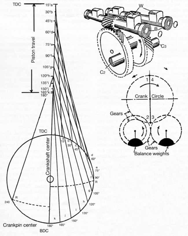
Left, study this diagram under a glass or draw enlarged version. Compare difference in piston travel between top dead center and 45 degrees and then between 135 de - grees and bottom dead center. This surprising difference results from changes in connecting rod angular ity. Top right, one form of Lanchester harmonic balancer. Rotating at twice crankshaft speed, revolving weights counter up-down engine shake.
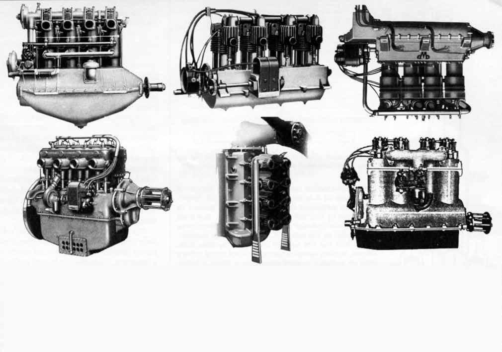
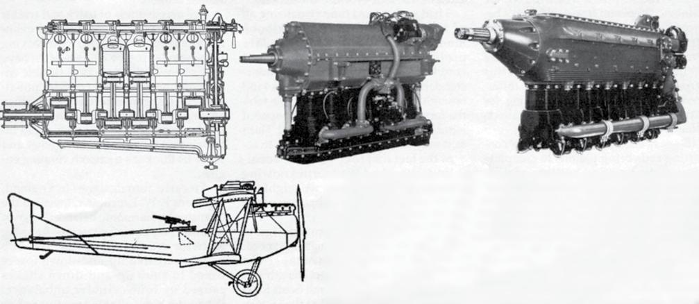
Top left, 100-hp Hall-Scott of 1918 had 606-cubic-inch displacement, weighed 420 pounds, and shook so bad that buyers of surplus Standard J-1 biplanes replaced it with much smoother running OX-5 and Hisso vee-8 engines. Center, primitive early aero engine by Glenn Curtiss shows his motorcycle background. Right, obscure German-made Werner & Pfleiderer circa 1918 was an early invested in-line engine. Water from radiator was pumped to hot cylinder heads and flowed up past cooler cylinder walls. Lower left, flywheel on one end and heavy propeller on other muted four-cylinder unbalance in this Massachusetts-built Sturtevant of 1918. Had reduction gear. Air entered cooling tubes in oil pan and was then ducted to carburetor. Center, prewar French Potez was mounted vertically with 90-degree gear drive to prop. Idea was to deliver cooling air uniformly to all four-cylinder heads. Right, 40-hp Rogers engine built in Texas in 1920s was air-cooled but had no cooling fins! Air flowing past smooth cylinders and massive aluminum rocker arm brackets was said to draw heat away satisfactorily. AIRPLANE ENGINE ENCYCLOPEDIA
fascinating to leaf through volume after volume and see how many inline aero engines have been used over the years and particularly in the 1910 to 1940 period.
Many of them look much like auto engines, but it’s common to encounter a significant difference. Lubricating oil was carried in oil pans just as in auto engines, but in one way or another the aeronautical versions were shaped to ensure oil feed to the pump whether a plane was climbing or gliding.
To provide adequate ground clearance for the tips of large-diameter propellers suited to engines operating in the 1200- to 1800-rpm range, upright in-line engines had to be positioned quite high in fuselage noses. To keep intake manifold length as short and direct as possible, carburetors were positioned close alongside the cylinders. This put them so high that gravity feed from fuselage tanks was not feasible.
It’s not easy to design a simple, reliable, and safe engine-driven gas24 AUGUST 2012
oline pump because this liquid isn’t much of a lubricant; it attacks shaft seals made of such available materials as natural rubber, flax, and cork, and it’s dangerous if it leaks out of a pump. A few pounds of air pressure in a tank would force gasoline to a high-mounted carburetor. It would also spray gasoline into an engine compartment if a fuel line broke, and this is one reason early airplanes often caught fire.
After the war ended in 1918, designers had time to put thought and testing into developing acceptable engine-driven fuel pumps, and as the 1920s wore on these came into increasingly wide use on new engines. The simple diaphragm-type fuel pumps we take for granted today began to appear on cars around 1930 and on small aero engines around 1940. It wasn’t a simple matter to develop a diaphragm material that would withstand both gasoline and prolonged flexing.
The problem of getting gasoline to high-mounted carburetors is one reason why many designers favored biplanes and parasol monoplanes. A tank in the center section was high enough to provide simple, safe, reliable gravity feed. Some planes carried their main fuel supply in a fuselage tank, and a hand-operated “wobble pump” beside the pilot’s seat transferred it into a high-mounted auxiliary tank for gravity feed to the carburetor. These pumps worked on the vane principle and got their name from the back-and-forth action of their handles. Pilots had to school themselves to pump more gas to the auxiliary tank at regular intervals.
Next time you see a photo of a German Albatros fighter of 1917, note that while the engine cowling as a whole is nicely streamlined, engine cylinder heads, with their exposed valve mechanisms, stuck up into the airstream. Because water cooling passageways could not effectively reach hot valve stems and springs, it was usual to leave these critical parts exposed to air
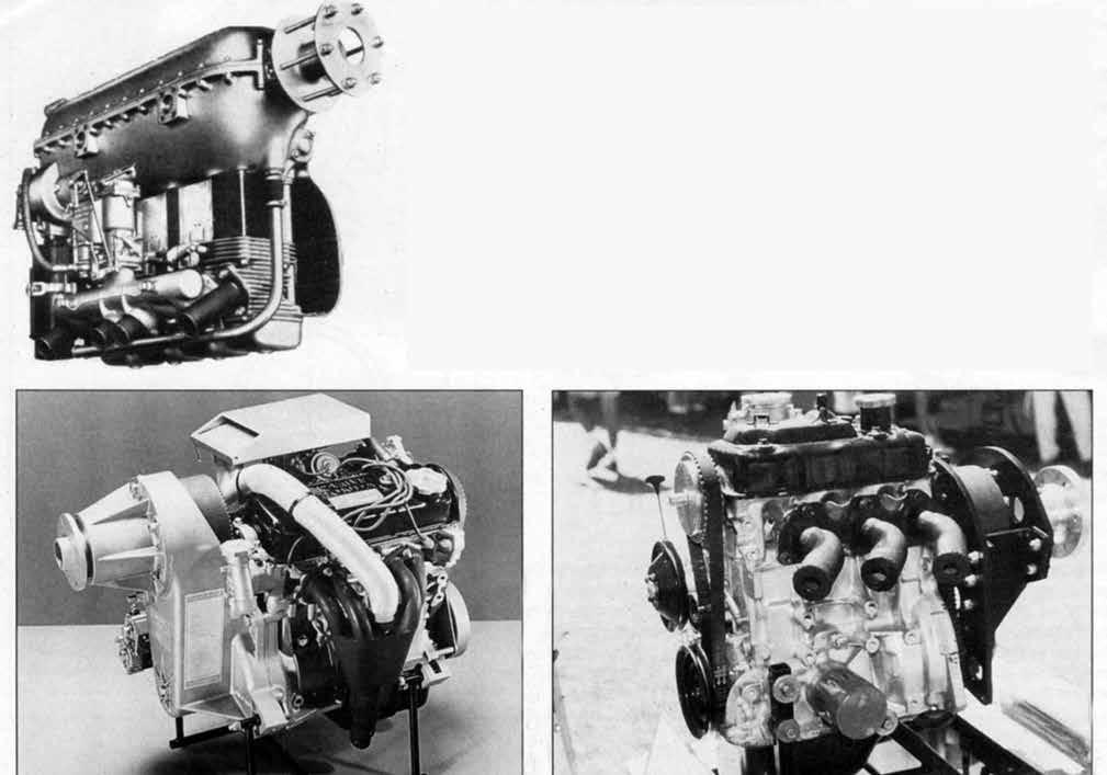
Left, introduced in mid-1930s, the diminutive Walter “Mikron” engine of 65 hp is still being made in the Czechoslovakian Republic. (According to information on the internet, the current distributor in the US is: Mr. Vitek Siroky, BLANIK AMERICA, INC., P.O. Box 1124,, Wenatchee WA 98807-1124. Tel .: (509) 884-8305. Email: blanikam@nwi.net Weight of this air-cooled engine with electric starter and alternator is 154 pounds. Bottom left – Honda-based CAM 100 now being made in British Columbia. Below right – Based on the three-cylinder Geo auto engine, this engine is converted by the Reductions firm of Manitoba. Modern high-revving light car engines usually have reduction drives for propeller efficiency.
flow as a simple but effective way of avoiding excessive heat buildup in the vital valve mechanism.
When the Kaiser’s War ended, discharged European military pilots quickly discovered that refilling the fuel tanks of war-surplus planes powered with big military engines also kept their pockets drained. Newspaper-sponsored competitions were held at Lympne in southern England to encourage the development of low-powered, economical sporting aircraft.
Unfortunately, the rules called for unrealistically small engines. Simply to climb to a useful altitude and cope with rough air, they had to be run at full throttle most of the time with predictable effects on reliability.
Observing the unsuitability of most of the Lympne entries for practical everyday flying, airplane manufacturer Geoffrey de Havilland cast about for a way to create a more practical engine. During the war the Royal Aircraft Factory had manufactured under license
COURTESY CANADIAN AIRMOTIVE
the French vee-8 Renault engine. It called its version of the Renault the RAF-4D. Parts for these engines were plentiful and cheap on the surplus market. De Havilland hit on the idea of using four cylinders, pistons, and other parts as the basis for a light but reasonably powerful civil aircraft engine.
Appearing in 1925 on the nose of the new de Havilland Gipsy Moth two-seat biplane, the resulting Cirrus engine had four air-cooled cylinders mounted in-line and delivered a useful 60 hp. The Moth quickly became popular, and it didn’t take other engine manufacturers long to introduce their own versions of the 4-in-line layout.
Welcome enough on chilly days but not in warm weather, hot air from the cylinders of Gipsy-style 4-in-line engines whisked back into open cockpits. Gobs of rocker arm grease and oil that had been squirted onto valve stems came with it. While a push on the rudder bar or movement of the head would
BOB WHITTIER
allow pilots to see what lay directly ahead, it was generally agreed that forward visibility wasn’t as good as pilots would like.
Better cowlings helped somewhat, but in 1928 de Havilland came out with a really good solution to the problem in the form of the inverted model of the Cirrus. This layout made it easy to discharge hot cooling air, exhaust, and lubricant drips downward and under the fuselage. Metal covers over the rocker arms kept airfield dust picked up by the propeller from getting to these vital parts. Forward visibility was much improved, especially in light cabin planes, which were becoming popular for serious cross-country flying.
Where upright in-line engines had carried lubricating oil in deep crankcases, a new approach was required on inverted engines. Cylinder skirts projected about two inches up into the lower part of the crankcase to keep oil from flowing down into the cylinders. Oil which
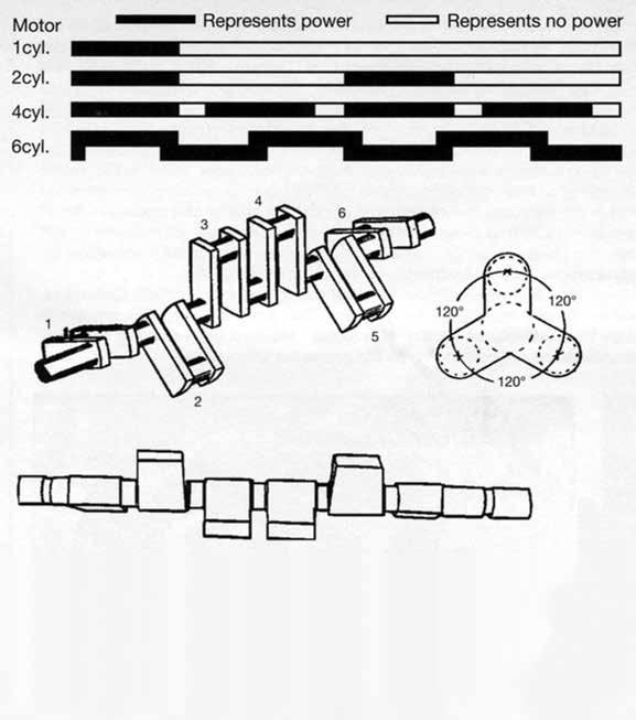
Diagram above shows power impulses of various engine types. Gaps between four-cylinder impulses are caused by diminishing torque input as con rods near bottoms of strokes. But generous overlap leads to six-cylinder smoothness. Also, 120-degree crank throw spacing elimi nates characteristic four-cylinder shaking. Most commonly used firing order is 1-5-3-6-2-4. Heavy machinery is needed to forge blanks for six-throw crankshafts.
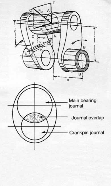
Top, this stress analyst’s diagram of forces acting on a crankshaft throw shows us how complex the process can be. Bottom, overlap of metal in main bearing and crankpin journal in a modern short-stroke engine’s crankshaft helps its rigidity.
collected around these skirts was pumped back to an oil tank located at some convenient place inside the cowling.
It all sounds so logical and neat. However, one can look at a hangar full of in-line engines and read a stack of service manuals without noticing that the in-line, four-cylinder engine has a hidden quirk. It’s a built-in characteristic called “fourcylinder unbalance” by engineers. One would think that with two pistons going up while the other two are going down, balance would be perfect. But it isn’t.
Textbooks on engine design use formulae and diagrams to explain it, and some of them can be hard to understand due to the specialized technical language used. What, you’ve never heard of first, second, and fourth harmonics? You can take the cylinder head off a fourin-line engine and watch the pistons go up and down for hours without noticing something that shows up clearly in diagrams of the geometry of moving parts.
It’s a demonstrable fact that pis26 AUGUST 2012
ton travel is uneven. This is because in the course of the piston’s movement from top to bottom of its stroke, the connecting rod assumes different angles which directly affect piston travel. An accompanying diagram of piston travel demonstrates this.
You’ll be surprised when you see the difference in piston travel in the arcs between top dead center (TDC) and 45 degrees, and between 135 degrees and bottom dead center (BDC). Engine designers use their knowledge of this surprising but very much present difference when working out valve timing, for example. This unequal travel also affects balance when running.
It’s easy enough to visualize how connecting rods bring pistons to complete stops at the tops and bottoms of their strokes, but few pilots or mechanics are aware of the forces involved. In an engine of 4-inch stroke running at 4000 rpm, the force necessary to bring a 1-pound piston to a full stop is in the neighborhood of 900 pounds.
In any four-cylinder, in-line engine the pairs of connecting rod crank throws are 180 degrees apart. Two pistons reach TDC and two reach BDC all at the same time. It takes many paragraphs to explain the technical reasons why, but it’s a proven fact that all four pistons at this point will, all at the same time, pull upward on the engine through the connecting rods. Also, this happens twice on each revolution of the crankshaft. Furthermore, all four pistons will push down on the engine when the cranks are at 90 and 270 degrees. Hence this built-in characteristic of “four-cylinder unbalance.”
I had such a hard time visualizing all of this from college-level text
book mumbo jumbo, so I wrote to an MIT professor asking if he knew where I could find an explanation of it understandable to a lay person. He was kind enough to reply, but his response took the form of an eightpage, single-spaced letter full of diagrams and figures! Hard as it may be to visualize, we have to accept the fact that four-cylinder unbalance exists. And it’s worth knowing about because someday we might encounter “mysterious” vibration while tinkering with engines.
It varies from one engine design to another depending on things like speed, piston weight, the length of the stroke (which affects connecting rod length and thus angles), and so on. Hall-Scott four-cylinder engines installed at the factory in Standard J-1 training biplanes in 1918 had big pistons and were bad shakers. Some old-time, straight-four marine engines seemed to their owners to be smooth running, but this was due to the tendency of heavy flywheels at one end and heavy reverse gears at the other end to mute the vibration. A few early aviation engines had flywheels at their back ends and heavy hardwood propellers at their front ends, which acted together in similar fashion.
The massiveness of truck and tractor frames can similarly conceal four-cylinder vibration. Modern light cars having four-cylinder inline engines often have very scientifically designed, flexible engine mountings. Four-cylinder unbalance can sometimes be clearly felt when an engine is idling, but when it speeds up, the impulses occur at such rapid intervals that they can blend together and make us think it’s a smooth-running engine.
An early auto designer in England, Professor F.W. Lanchester, invented the “Lanchester harmonic balancer” shown in an accompanying drawing. Running at twice crankshaft speed, the bob weights created up-and-down forces timed to snub up-and-down shakes caused by four-cylinder unbalance. When the bob weights face toward or away from each other, they cancel their own forces so they do not create side shaking. This system was used in a small number of American car engines of the 1920s, but the growing popularity of straight-6 and vee-8 engines put it on the sidelines. It is used today in the 4-in-line Mitsubishi engine that powers such vehicles as the Dodge and Plymouth compact vans. Mitsubishi calls it the “silent shaft” system. See illustrations of it in overhaul manuals for these vans. As far as is known the Lanchester balance has never been used in aircraft engines, probably for such reasons as cost, weight, and the saying that “Parts left out of a machine never give trouble!”
When a company has tooled up to make cylinders, pistons, and related parts for a 4-in-line engine, it is tempting to offer a more powerful one by using two more sets of these parts to create a 6-in-line engine. But in doing so, an engine is created that involves much more than merely two more cylinders.
While several different positionings of crank throws have been used in six-cylinder crankshafts, the most common form has the three sets of crank throws set at 120 degrees to one another. This automatically and in expensively eliminates four-cylinder unbalance vibration.
However, adding two extra cylinders means we now have a longer crankshaft, and this setup brings in the serious problem of crankshaft torsional vibration. The crank throw nearest to an airplane’s propeller or a car’s clutch must transmit power impulses coming from the other five throws. Early designers were often driven to distraction by repeated crankshaft breakage. One experiment showed that between one end of a six-cylinder crankshaft and the other, torsional vibration could cause the flexing of as much as eight degrees.
It’s easy to say, “So, make the

crankshaft stouter!” Doing so can call for also redesigning and retooling a crankcase, and it goes against aviation’s need for lightness. An early solution in the auto field was to install spring-loaded, multipledisc torsional vibration dampers on the front end of crankshafts. Later six-cylinder engines in popular cars had dampers which made use of rubber inserts bonded to the metal parts. In the aviation field the usual solution was much skillful engineering and testing. Where some light car 6-in-line engines had only four crankshaft main bearings, usual aviation engine practice was to have seven.
Achieving uniform delivery of fuel mixture to all cylinders becomes more complicated when we move from four to six cylinders. Many different manifold designs can be seen in old engine books. Some aircraft engines such as the more powerful versions of the four- and six-cylinder Menascos of the 1930s had gear-driven superchargers mounted in their back ends. In addition to boosting power, these contributed to uniform mixture distribution by pressurizing comparatively simple, straight intake manifolds.
Early in-line engines such as the Cirrus cooled adequately because their cylinders rode out in the slipstream. Getting adequate air to the rear cylinders of 6-in-line engines was accomplished by fitting a sheet 28 AUGUST 2012
Above left, 1914-1918 straight-6 engines such as this 160-hp Mercedes were brutes. This one had 900-cubic-inch displacement and weighed 700 pounds. Note bad forward visibility in HansaBrandenburg two-seater. Above center, 1939 Ranger gave 165 hp from 411 cubic inches and 350 pounds. Above right, 200-hp Menasco Buccaneer had gear-driven supercharger to provide uniform mixture feed to all six cylinders. Note air scoop on one side of cylinders and baffles on the other.
metal plenum chamber to one side of the cylinder row. Air ramming into it fed air under acceptably uniform pressure to all cylinders. As it fed crosswise between adjoining cylinders, it met sheet metal baffles that ensured good flow past cooling fins on the side opposite from the plenum chamber.
In-line engines got started as a result of their simplicity of design and construction. Their low frontal areas made them blend very nicely into the slim fuselages of tandem-cockpit planes. They were ideal for the smaller classes of racing planes. But when cabin planes with side-by-side seating and proportionally wider fuselages became popular, this narrowness became less valuable. Long crankshafts and crankcases added weight. A 165-hp Warner radial engine’s cowling has an appreciably larger air inlet opening than does that of an in-line Ranger of similar power. One would think a Ranger-powered Fairchild 24 would thus be faster, but pilots don’t notice any significant difference in speed. The Ranger weighs about 50 pounds more, which means coaxing more lift from the wings that causes more drag. So things work out about equally. You’d think a slim Ranger engine would give better forward visibility than a fat, round Warner, but pilots of Ranger-powered F-24s say that because the Ranger projects so much farther forward, the peak of its cowling thus rides higher when in three-point position and blocks visibility to the front quarter, as seen from the pilot’s east. We have to consider each airplane and engine as an individual case.
Today, in-line engines are coming back into the homebuilt aircraft movement. Four-and-six cylinder inverted movement. Four-and-sixcylinder inverted in-line aero engines are still being manufactured in the Czech Republic and are finding their way to the United States in small numbers. To meet the need for light weight and compactness in modern cars, both three- and four-in-line engines are being used. Materials and manufacturing methods have advanced tremendously since the 1930s, and it’s now commonplace for car engines to run over 100,000 miles without major repairs. So they appeal to homebuilders. To achieve power from these quiet, small engines, rotational speeds in the 5000- to 6000- rpm range are usual, so reduction drives are needed to turn propellers at aerodynamically efficient speeds. This adds cost and weight, but we have to do the best we can with what’s available.
By around 1940 horizontally opposed engines had become standard on light planes, and because they are still much in the majority, we’ll look into them next month.


