

A HOME MADE LUTE
Hilde & Hans Vaatstra
A HOMEMADE LUTE
A HOME MADE LUTE
Hilde & Hans Vaatstra


PREFACE
This book is the culmination of a life shared between two people who found each other through their love for the beautiful things that the world has to offer.
Alongside his professional life as an economist, Hans Vaatstra had a passion for music and musical instruments. Over the course of the years, he set up his own workshop. It was there that he was truly in his element. He selected the wood, determined the shape, made decisions about rosettes, tuning pegs, varnish and strings. He built musical instruments with his own hands and simple tools. At first guitars – which he could play with some proficiency – and later other instruments, including an arpeggione, a baroque cello and lutes.
Hilde Vaatstra became an accomplished photographer by taking courses at the Photography School of The Hague, among other things. From a young age, she always brought a camera with her on holiday. She developed her own black-and-white photos and was enthralled by the magic of the darkroom: how an image emerges slowly on a sheet of white paper plunged into a bath of chemicals, and the influence she could have on the result. Photography as the magic of light.
The idea for a joint project came from Hans. He wanted to build a lute and asked Hilde to record every stage of this artisanal process. This gave rise to a wonderful exhibition at the Centrale Discotheek at De Doelen concert hall in Rotterdam in 1984. Hans tried to get the work published but didn’t have any luck. Life went on and the lute book got shelved.
In 2023 Hilde was chatting to an interested visitor about Hans’ skills as a musical instrument maker when she recalled the lute project. She showed it to him and he was enthused. “You should do something with that. It’s beautiful!” You’re right thought Hilde. We should. And that’s how it came to be.
A Homemade Lute unites two worlds. It is an ode to the magic of creating – with light, hands and music. Both looking and listening.
With thanks to Adrian Farmer for his critical reading of the English text, Harry Fuhler for the precision work and Johanna Fuhler and Elke Beekman for the production management.
INTRODUCTION
Years ago I became convinced, as many classical guitar players sooner or later will find, that lute music should be played on a lute. The music in its original setting played on a lute sounds incomparably better than transcriptions played on a guitar. Moreover, it is much easier to play with the number of strings ‘at hand’ that the composer had in mind. Unfortunately it would appear easier to learn the fingering of many bass chords and reading tablatures than to buy an affordable lute of sufficient quality. In fact there is a remarkable inconsistency in the abundance of guitars and the rather small musical literature written for it, whereas there is an immense literature for the lute and a severe scarcity of instruments.
At that time I had some experience in constructing guitars and started making my first lute after gathering information from various sources. Since then, some construction kits have become available as well as a very useful booklet on lute construction issued in 1978 by The Lute Society. It seems that home construction of lutes is the best way to enhance their use.
This book does not pretend to embody a complete or fundamental study of lute construction. It is the photographic account by Hilde Vaatstra of my way of constructing a lute. It also goes to show that building a good lute is within the abilities of the craftsman working with simple hand tools. The photos do not follow the construction of one single instrument as can be seen in some differences in wood and ornamentation. The drawings (1-4) on pages 12 to 15 give a lute model that has emerged from three sources:
1. A drawing obtained from the Germanisches Nationalmuseum (Nürnberg, Germany) of a lute by Laux Maler (about 1550);
2. An engraving by F. de Troy of Charles Mouton (1626-1710), available at the Kunstmuseum Den Haag (The Hague, The Netherlands);
3. A very fine sounding baroque lute, built by a Rubio pupil.
Of course, listening to and, wherever possible, the handling and tapping of existing lutes gave me an idea of the sound I am striving for.
The report might encourage all those interested and save time spent in finding out where to obtain the required information, materials, drawings, etc. The time saved in this way may hopefully be spent on building lutes and for the development of better methods of construction or adaptation to your own particular skills. A sound piece of advice to the enthusiastic beginner is to set out not only with one lute, but to tackle two or three right away. Whenever a part breaks down or does not turn out to be completely satisfactory you do not experience the frustration of the whole undertaking coming to a temporary halt. And in case parts turn out right in quantity you then have the option to match the best fitting components together to assemble the best instrument and use the others for your second best. Do not be surprised to find eventually that your second lute turns out to be the better sounding one. This has in fact been my own first experience and it has encouraged me to go on building instruments.
Hans Vaatstra


mm


DRAWING 4

1 | CONSTRUCTING THE MOULD FOR THE BODY
Drawing 1 on page 12 shows that the body of a lute consists of identical (congruent) segments called ribs. Having decided on the outline of the soundboard and the number of ribs, in our case 11, the wedge-shaped mould for the ribs is determined. It is constructed of a good quality 6 mm hardwood
ply and three 16 mm thick (hardwood) wedges (photos 1 and 2).
These wedges were made with the greatest accuracy with an angle of exactly 16.363636 degrees (180 divided by 11) and perfectly perpendicular cuts. 16


PHOTO 1
PHOTO 2
CONSTRUCTING
Photos 3 and 5 show that the plywood pieces that will become the sides of the mould have different dimensions due to their thickness. The wedges were used to find the size-difference of the sides and the area where they have to be bevelled (photo 4). These areas were marked with a pencil line and planing the narrowest side followed. Then the sides and the three wedges were glued together as shown on photo 5.
This is a tricky job because clamping might force the wedges from their place. If necessary secure them
to one side with one or two panel pins. The wedges were positioned perfectly parallel and perpendicular to the straight side of the mould. The angle of the mould was determined by the angle of the wedges only and in no way by the bevel of the planed side, which should just butt against the other side.
After the glue (preferably epoxy cement) had set, the waste of the broader side was planed. The sharp egde of the mould was sanded round so as not to acquire a knife edge.


PHOTO 3
PHOTO 4, 5
CONSTRUCTING THE MOULD FOR


After roughly sawing the protruding ends of the wedges, the mould is clamped parallel to a workbench. Use a piece of wood half the thickness of the thickest part of the mould as a spacer (photos 6 and 8).
Two holes of 5 mm ∅ are drilled near the ends of the mould and seven holes of 16 mm ∅ are drilled parallel with the rib side at a distance of 25 mm from the curved edge (photo 6).
In the seven holes, pieces of plastic tube, as used by electricians, were glued with epoxy cement (photo 7). These tubes will serve as a grip for clamps and add substantially to the stiffness in the mould. After the cement has hardened the tubes are filed flush with the sides.
Now check both sides of the mould against your drawing and trace the exact contour on both sides, allowing 3 mm in total for the thickness of the ribs and the ‘cover’ of the mould. After the mould is clamped firmly to the workbench using a square and fragments of wood to get it into the correct position (photo 8), the rib side is planed and sanded to its precise shape (photo 9).
PHOTO 6, 7


PHOTO 8
PHOTO 9
CONSTRUCTING

Photo 9 shows the use of a sanding block, made of a perfectly square billet of wood, covered on one side with a rough grit sandpaper and on the opposite side with a medium grit. The mould is completed by fitting and glueing a strip of thin plywood. Let the grain of this plywood run across the strip to make it easily pliable. Secure the strip, whilst the glue dries, with small clamps and/or elastic bands so that it fits perfectly to the original mould (photo 10). After the glue has dried, the mould is sanded, ensuring that the edges are square. Be careful not to ‘round’ the edges during sanding. The mould should then be finished with several coats of a two component floor lacquer, which will protect it (if you are careful) during the building of many instruments (photos 11 and 12).


PHOTO 11
PHOTO 12
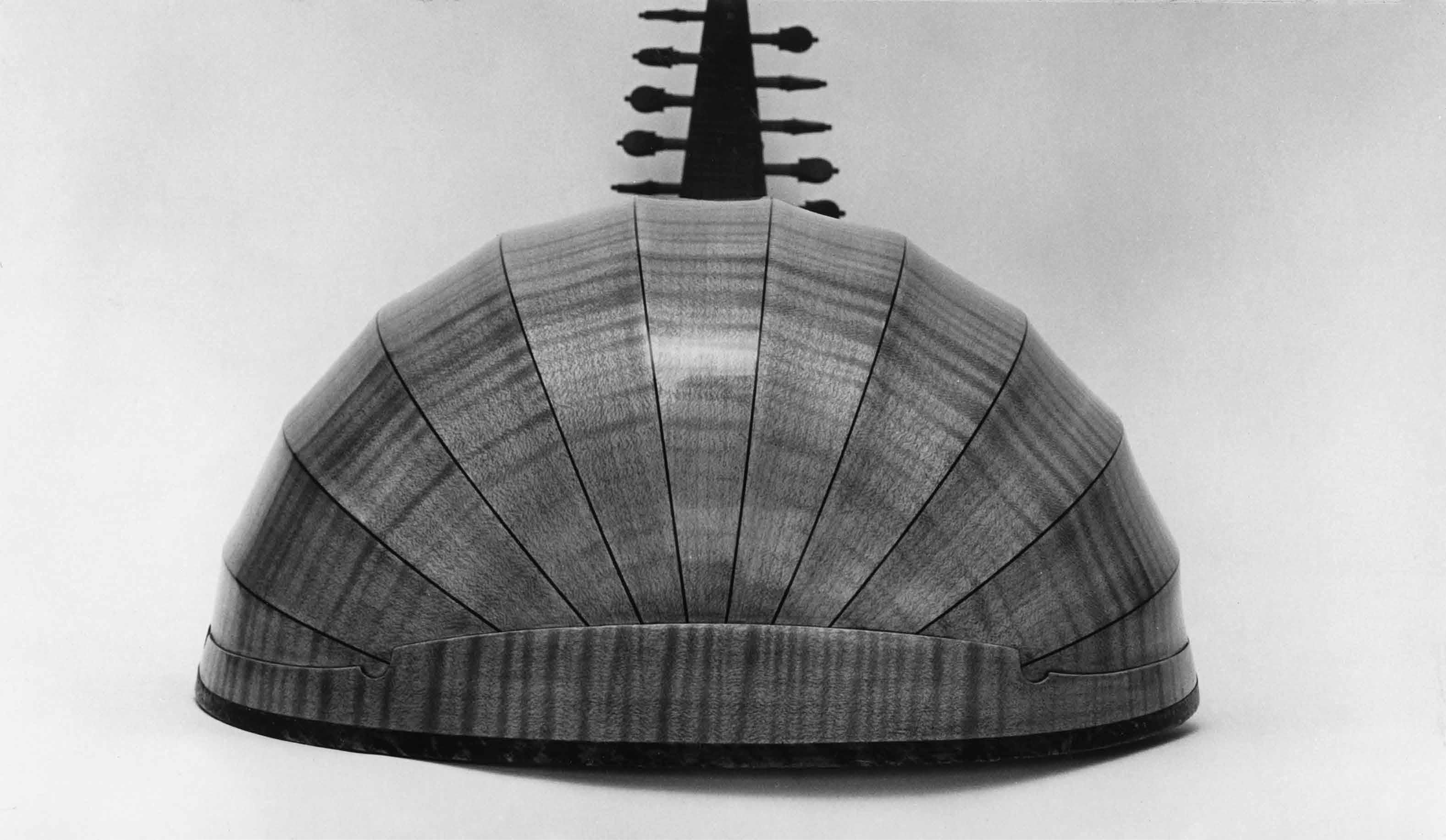
2 | CONSTRUCTION OF THE BACK
Before the construction of the body is completed, the back is rather fragile. Once finished it will turn out to be relatively very strong just like an unbroken egg shell.
For the first couple of instruments I used unflamed maple, which can be easily planed and is relatively easy to bend. If you decide to use flamed maple, the end result will look amazing if the flame is matched and runs continuously across the ribs. However, flamed maple is more difficult to work, requiring very sharp hand tools including a toothed blade plane, plus a bending iron (as used by
luthiers) and lots of patience. More experience in working with figured woods will certainly make it easier.
A further refinement is to make the ribs somewhat thicker at the beginning and work them into a convex shape when the body is completed. Photo 1 on page 17, gives a nice example. These refinements relate to the appearance of the lute only and to a lesser degree to the eventual sound quality. Good seasoned unflamed maple is as suitable for an excellent instrument as the finest flamed brands.
548 mm


PHOTO

The maple strips were planed and scraped to a thickness of ±1.6 mm (photos 13 and 14). Further finishing and sanding of the completed body later on gave them a final thickness of 1.2 to 1.5 mm. At this stage, however, the strips were no thinner than 1.6 mm.
Before planing lay the strips in the order they were cut from the log. This can be done easily by positioning the grain patterns of the strips in the same direction. Number them with a pencil, each strip on the same side in the same corner and renew the numbers after planing and scraping. Make a template of heavy paper of the shape of one rib, working it around the mould.
The contours of the ribs were traced on the numbered sides of the maple strips with a template (photo 15).
Next, the ribs were roughly cut with a knife, a deep throat jewellers saw or a Coping saw, leaving about 2 or 3 mm of wood outside the pattern of the rib.
Some spare ribs were prepared in case one or more of them break during the upcoming bending process.
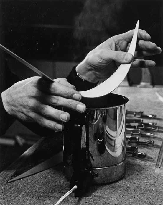

Photos 16 and 17 show steam-bending of the ribs, which is a perfect method when you are using unflamed maple. Flamed wood, on the other hand, should be bent my means of a hot bending iron, as used by violin- and guitar makers.
Use one of the ribs to try out this process. After about twenty seconds of steaming the wood is pliable enough to bend it into shape. Hold the rib curved for about one or two minutes to dry. After drying the wood will spring back somewhat, you have to reckon with this during the bending process. Notice the way the left hand holds the rib (photo 17).
PHOTO 16, 17


PHOTO 18, 19
PHOTO 20, 21

After bending the rib was clamped to the mould (photo 18). Care was taken that sufficient wood protruded on both sides of the mould to facilitate final shaping of the edges of the ribs. Use wooden cauls to avoid scratching or denting the material (photo 19). The ends of the ribs are fixed to the mould by homemade hooks of 3 mm thick brass wire (photo 19). Cauls are not necessary here, because the end of the ribs will be cut off on the neck-side of the body, and covered with an endclasp at the other side.
The edges were planed and sanded flush with the sides of the mould. Photos 20 and 21 show the use of a small plane and the sanding block. This
was a delicate operation because the rib edge had to be shaped precisely with the mould still left in tact. After one edge was ready the clamps and hooks were turned over (one by one to hold the ribs steadily fixed) so that the other edge could be shaped.


PHOTO 23, 24
After the rib has been sanded flush with the mould at both edges, the clamps are loosened just enough to shift the mould about 3 mm to one side. Keep the corresponding edges of the mould and the rib parallel. The protruding edge of the rib can now be easily glued to the sheet of veneer (photo 22). When shifting the mould, care must be taken not to shift it longitudinally. Before the segments are glued together, the waste veneer on the outside must be cut off (photo 23) and the sides should be planed and sanded smooth (photos 24 and 25).

PHOTO
The precisely shaped ribs were glued consecutively together to form the shell. Self-adhesive tape served to hold the ribs in place during setting of the glue. Use the elasticity of the tape to stretch well against the wood (photo 27). Photo 26 shows how a pencil mark ensures correct positioning of the next segment to its predecessor.


PHOTO 27
PHOTO 26
Note the abundance of veneer on the inside of the body, helping to keep the body in shape during assembly (photo 28).


PHOTO 28

Without the support of veneer at the inside, the body has a tendency to stretch into an oval shape. To compensate for this, an accurately bent strip of maple was glued to the inside of the shell in order to hold the bottom outline in shape (photo 29).
Next, the end clasp, which is taken from a similar strip of maple as the ribs, is bent and glued into place.
Cut the strip 45 x 4 cm and trace a perpendicular line in the middle (photo 30). Smooth the outside of the body where the end clasp is to be glued with scraper and sand paper. The end clasp visible in photo 31 is bent until it fits closely round the lower end of the lute body. At this stage the centre of the strip is kept some millimeters above the edge of the body. Photo 31 shows that the ends of the strip protrude about 25 mm. After the glue has been applied the end clasp is clamped firmly from the centre outward (photo 32). Use clothes pins at the ends for a snug fit and remove all squeezed-out glue with a damp cloth. After the glue has set, cut the end clasp parallel to the end of the body, leaving 1 mm for later finishing.


PHOTO 30, 31
PHOTO 32
Photos 33-35 show how a neck block was fashioned out of a half cylinder of pine, and glued to the shell with the help of a counter mould.
The half cylinder cut from the mother block and an extra end block in finished state are shown on photo 33. The height of the cylinder is 50 mm and the radius is 48 mm. The half cylinder is tapered until one side has a radius of 13 mm. The exact taper must continuously be checked with the taper of the body end, using a template. Glueing the end block requires local removing of veneer from the inside of the body and making a counter mould for clamping. The inside of this counter mould was padded with self adhesive latex foam (photo 34).
Photo 35 shows how the end block is clamped in place. Epoxy cement was used for strength and for its filling capacity, needed where the carving of the block does not fully match. At this stage the end block protrudes slightly above the edge of the body.


PHOTO 34, 35
Now the body has sufficient strength to remove the veneer from the inside. Scissors, a small plane and sand paper are the tools for this operation.
The joints may need repairing at places where they do not fit exactly or where the veneer has broken. Do not try to force joints together but instead glue chips of maple and/or pieces of veneer in chinks, occasionally widening these with a sharp knife and/ or sandpaper. Watch that the grain and colour of the maple inlay matches the adjacent rib as best as possible.
When the joints are to your satisfaction, the inside of the body is carefully smoothed with scraper and sandpaper (photo 37). Now tape is glued to the inner seams to provide additional strength (photo 36). A strong kind of paper or silk used to be selected for this purpose, but cotton tape works as well. I used tape of glass fibre cloth, bonded with two component lacquer, which did the job perfectly. The lacquer or glue is applied with a small brush, the tape laid on and pressed down. When lacquer is used a second layer is applied over the tape.
Photo 38 shows the finished inside of the lute body with a label glued to the keel rib. Remember that you cannot write down your name and the date after the lute body has been closed!

PHOTO 36


PHOTO 38
PHOTO
To extend the gluing surface for the neck-joint and to match the body-end to the width and the thickness of the neck, the neckend of the body had to be sawn at an angle. Three points were marked to find the guiding line (photo 40): first the thickness of the neck (2 cm) was marked on the centre of the keel rib (photo 39), then the width of the neck at the joint (±10 cm) gave two points on the top ribs.
A pliable ruler (photo 40) pressed snugly to the ribs and connecting the three marks provided the means for tracing a line for cutting. Photos 41 and 42 show the cutting and smoothing of the gluing surface.


PHOTO 39, 40
PHOTO 41, 42
3 | THE NECK
The neck (drawing 3) can be constructed out of a single piece of wood. Maple, (Honduras-) mahogany or similar stable hardwoods are suitable. The relatively heavy hardwood, however, works more or less as a muffler on the fragile lute body. For this reason, pine, spruce or cedar is often used for the neck, veneered on the back side. Quarter sawn pine
covered on one side with the ebony fingerboard and a hardwood veneer on the rounded backside gave me a very stable, yet lightweight neck. The following will show the use of pencil cedar, veneered with coromandel (an ebony species). The taper of the neck in depth as well as in width may be adapted to the wishes of the player.
Photo 43 shows the cedar block after the bevel to fit the body and the width taper have been provided, by sawing and planing. First the bevel was made as accurate as possible. Next a centreline was traced exactly in line with the centreline of the soundboard side of the body. Next the exact dimensions of the neck are traced, working symmetrically to the centreline. Photo 44 shows the finishing of the cedar with sandpaper after rough shaping with a small plane.
Photo 45 shows the set up for glueing the cedar to the body. Extreme care was exercised in order to coincide the centre of the body with the centre of the neck. A workboard with a dead straight line in the middle is indispensable. At this stage the length of the neck was still some millimeters oversize.


PHOTO 44, 45
Securing the butt-joint with dowels, as shown in photos 46 and 47, may be superfluous with regard to constructional strength. However, I personally feel a better contact is achieved from an acoustical point of view.


PHOTO


PHOTO 50, 51
PHOTO 48, 49
Photos 48-50 show the veneering of the back of the cedar neck (photo 48). First, a template was made of light cardboard (photo 49). The piece of veneer was oversize in width as well as in length. Glueing veneer to the curved surface was simplified by moistening the unglued side. Photo 50 shows how the neck was elevated by means of a billet of wood, facilitating the use of rubber bands. Where necessary wooden cauls were forced between the rubber bands and the veneer. Photo 51 shows the veneered neck.
Final shaping of the edges will be executed when the fingerboard has been glued to the neck.
With the neck now in place, you can proceed to shape the body. Photo 52 shows the finishing of the outer side of the body with a slightly rounded side of a scraper blade. Care must be taken not to round off the ribs at the joints and to make them no thinner than 1.2 mm. As stated before, the ribs can be worked to a concave shape, bringing out the veneer inlays. Thickness of the ribs will then be about 1.5 mm at the edges and about 1 mm in the middle. Note that for this operation, the lute body is held firmly in place to the workboard with rubber bands. Work lengthwise in the direction of the ribs only. After finishing the outer side with the scraper blade, polish the surface (photo 53).


PHOTO
PHOTO 53
4 | THE SOUNDBOARD
For the soundboard (drawing 2), roughly sawn and carefully dried European pine was bought from a specialised supplier. The wood was stored for some months in the workshop, so that it had the same humidity as the room when construction
took place. Fine and even grained quarter sawn soundboard wood is easy to plane and can give an optimum balance between strength and weight of the finished soundboard.
mm
mm
mm
mm


PHOTO 54, 55
PHOTO 56, 57
Photos 54 through 57 show the joining of the soundboard halves which have been planed to about 4 millimeters. Notice that the grain pattern is symmetrical on either side of the joint and that the finest grain runs in the middle of the soundboard.
The joint should fit perfectly, resulting in an almost invisible seam. Plane and sand the edges to be glued perpendicular and straight until the two halves when held together against the light do not show any chinks. A spirit level faced with sandpaper was very useful for sanding.
The set up for glueing consisted of a flat workboard, covered with waxed paper, to which a wooden strip was nailed to keep one of the soundboard halves fixed. The other halve was secured with push pins. Before glue was applied a batten of about 4 mm thick supported the joint. The batten was pulled away before the joint was clamped, resulting in an even sideways pressure. Photo 57 shows how two battens were clamped together and forced apart in the middle to achieve an even pressure perpendicular to the soundboard.


PHOTO

After the glue had set both sides of the soundboard were scraped with a cabinet scraper (photo 58). The best looking side was scraped and sanded and became the outside (photo 59). The soundboard was turned over and planed to final thickness with use of a clock caliper (photo 60), about 1.5 mm for a good dense quality spruce. Softer spruce and cedar must be worked thicker, say to 2 mm. These figures should be regarded as an indication. To be on the safe side the beginner should not go under 1.5 mm. As a rule the area of the rose is some tenths of a millimeter thinner than the rest of the soundboard.


Photos 61 through 64 show several examples of traditional roses, created by craftsmen.
PHOTO 61, 62


PHOTO 63, 64
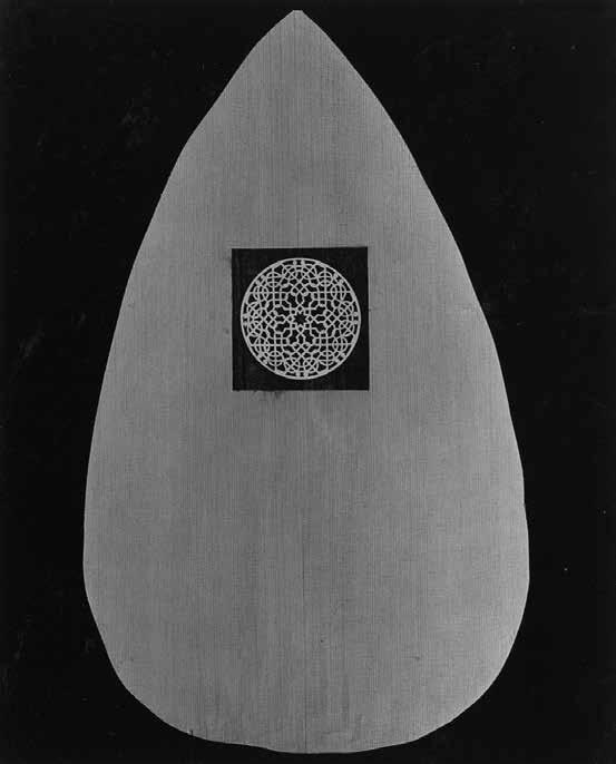


PHOTO 65, 66
PHOTO 67, 68

Before the rose carving could start the exact centre had to be established by a small hole (1.5 mm Ø).
Next, a paper pattern was glued to the back of the soundboard. The experienced wood carver is at an advantage here, because carving the rose with a knife goes rather fast and will result in a delicately defined pattern. The method as shown in photos 65 through 68 is more laborious, but in this way an unexperienced carver can also get a good result, using a small drill, fine deep throat jewellers saw, jewellers files and lots of patience. As sawing is done from the back you have to reverse the usual direction of the saw blade.
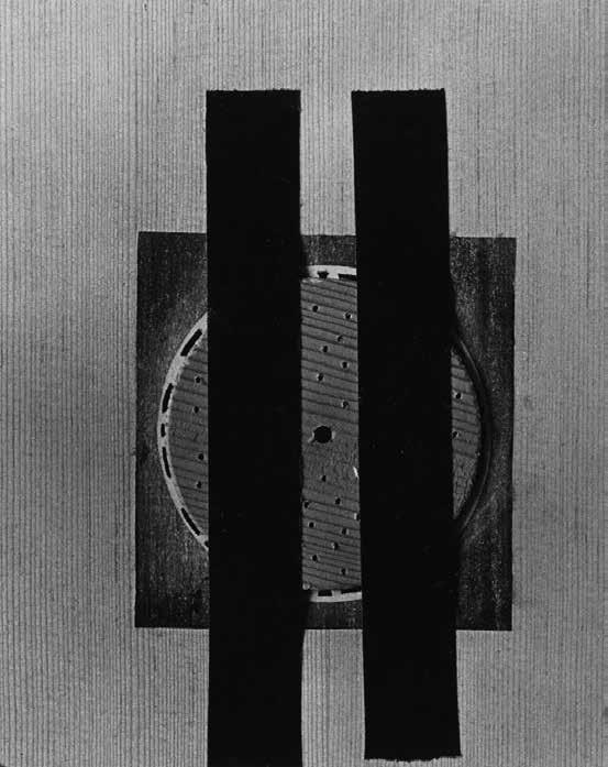
Photo 69 shows how a piece of wood was taped to the back of the soundboard so that the circle cutter could find a centre hole. This cumbersome method was followed because carving the rose from the centre to the circumference minimises the risk of breaking. Between the circles (photo 70) a criss cross pattern was carved.
After completing the rosette the underside of the soundboard was marked out (drawing 2 on page 61).
A fine grain spruce was selected for the bars. The end grain runs upright, (quarter sawn) perpendicular to the soundboard. The curved ‘bass bar’ and the two small ‘treble bars’ near the bridge measure approximately 3x10 mm, the six transverse bars about 5x15 mm and the two small bars, supporting the rose, 3x4 mm. These figures depend on the qualities of the wood and the characteristics of the unbarred soundboard. The finished assembly of soundboard and bars should be elastic enough to vibrate, light enough to give a brilliant tone and strong enough to withstand the string tension for years and years. The last property was enhanced by giving the bass bar and the first two transverse bars near the bridge a shallow curve so that the soundboard is ‘lifted’ about 2 mm at the bridge area (photo 71). This strengthens the soundboard considerably and facilitates the use of a bridge lower than what would be possible on a flat surface. Thus the bending movement of the bridge on the soundboard, caused by string tension, is diminished.
Glueing the bars must be executed very carefully. A loose bar causes buzzing, which can be remedied only after removing the whole soundboard. Photos 72 through 74 show the shaping of the bars. The section of a finished bar would show a pointed pyramid. The ends of the bars are scalloped (photo 74). Bending the bass bar is easily accomplished by pressing it gently with a rocking motion to the iron housing of a hot soldering iron.


PHOTO 71, 72
PHOTO 73, 74
Photo 75 shows how the outline of the soundboard near the neck joint was traced precisely, after positioning the soundboard with push pins onto the workboard. The centre lines of the workboard, the soundboard and the body-neck assembly coincided exactly! Photo 76 shows how the cut-outs for the pointed ebony inlays were made with a scalpel. The ebony pieces had the same thickness as the soundboard and were glued in place (while oversize) with a small bar, which was glued simultaneously to the soundboard (photo 77). Next, soundboard and ebony inlays were sawn off together after the glue had set, forming an edge where the ebony fingerboard would match later on (photo 78).

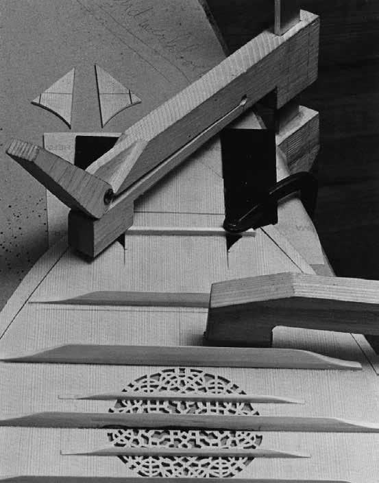


PHOTO 75, 76
PHOTO 77, 78
5 | ASSEMBLY
As the exact dimensions of the bridge depend on the slight curvature of the soundboard as well as the bevel of the fingerboard, the construction of the bridge and fingerboard are shown in this chapter.
In fact the top was fixed temporarily to the body with adhesive tape, facilitating measurement of the bevel of the fingerboard, the height of the string holes in the bridge and the exact position of the first and last holes in the bridge to achieve a correct playing action.


Photo 79 shows how the roughly sawn oversize ebony fingerboard was scraped to fit snugly to the soundboard. If this works out well, the fit will suggest that the two pointed pieces are part of the fingerboard (photo 80).
For an average good playing action the string height at the nut will run from the treble to the bass string from 1.2 mm to 2 mm and at the body joint from 2.5 mm to 4 mm.
Photos 81 and 82 show how the measurements were taken and how the soundboard and fingerboard were provisionally taped and clamped. Apart from various rulers a string was very helpful in this process.


PHOTO
PHOTO 82


PHOTO

Drawing 5 and photos 83 and 84 show the design of the bridge. The exact positions of the string holes were plotted according to the measurements as pointed out in the previous pages. Apart from that, the future player of this lute had specific wishes regarding the distances between the strings, commonly known as the string spacing.

Note the slight curvature at the underside of the bridge (photo 84), to match the local curvature of the soundboard. Photo 85 shows how this was accomplished at the beginning of fashioning the bridge, which was made out of an unflamed, straight grain piece of maple.
Photos 86 through 90 show several stages of shaping the bridge.
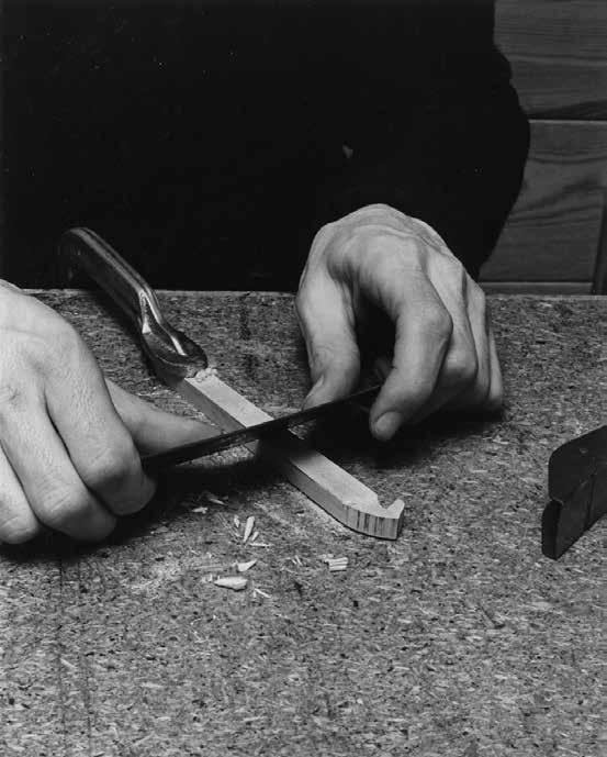

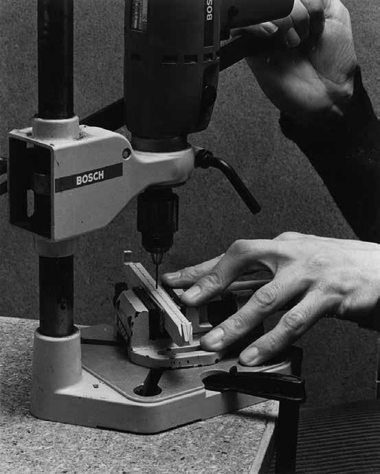
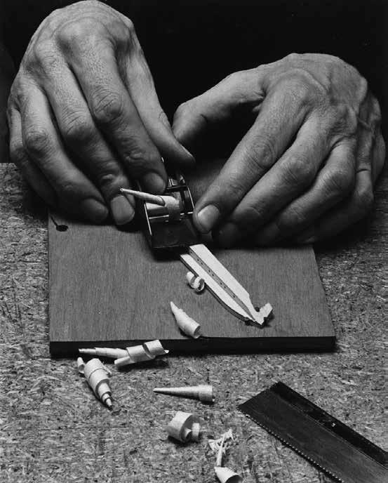
PHOTO 86, 87
PHOTO 88, 89


Photo 91 shows how the bridge was clamped to the soundboard (drawing 2) in order to test the fit. Before glueing it to the soundboard the maple bridge was stained dark brown and given two layers of lacquer to prevent colouring the soundboard while glueing. The glueing side of the bridge was masked with tape during staining and lacquering.


PHOTO 92, 93
PHOTO 94, 95


Photos 92 and 93 show how the edge of the shell was prepared for glueing on of the top. On photos 94 and 95 can be seen that the top was fixed with nails to a workboard. The centre line coincided with the centre line of the workboard. Pieces of lightweight cardboard prevented the slightly curved top from being flattened by the pressure during setting of the glue. Cauls of the same thickness as the top served to keep the neck at the right distance to the workboard. As the bridge was already glued to the soundboard, a hole was made in the workboard.
Photos 96 and 97 show the glueing and final shaping of the ebony fingerboard.
PHOTO
6 | THE PEGBOX
The next pages show how the pegbox (drawing 4) was constructed. Maple was used for this part of the lute.
The pegs are bought ready-made, slightly oversized. The trick to get a perfect fit for the pegs is to shape the holes with an appropriate reamer and to adapt the shafts of the pegs to each hole individually. Reamers for this purpose are obtainable in specialist shops.
DRAWING 4


The four pieces, forming the framework of the pegbox, are glued together simultaneously with help of a clamp and a rubber band (photo 98).
The framework is glued to the back of the pegbox (photo 99).
The small pegholder for the treble string is constructed out of a solid piece of maple (photo 100).
The treble string pegholder is secured during setting of the glue by means of a rubber band (photo 101).

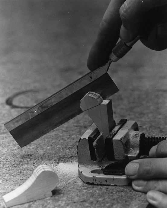


PHOTO 98, 99
PHOTO 100, 101
Slightly undersized holes are drilled in the pegbox (photo 102).
Photo 103 shows how the pre-drilled holes were given the appropriate taper with a reamer. The reamer was marked with tape in order to stop reaming on equal distances in each hole. A peg was fixed each time in the preceding hole to prevent the sides from bending during reaming.
Photo 104 shows that the pegbox itself served as a guide for the pencil that traced a guideline along which the neck was sawn off exactly (photo 105).

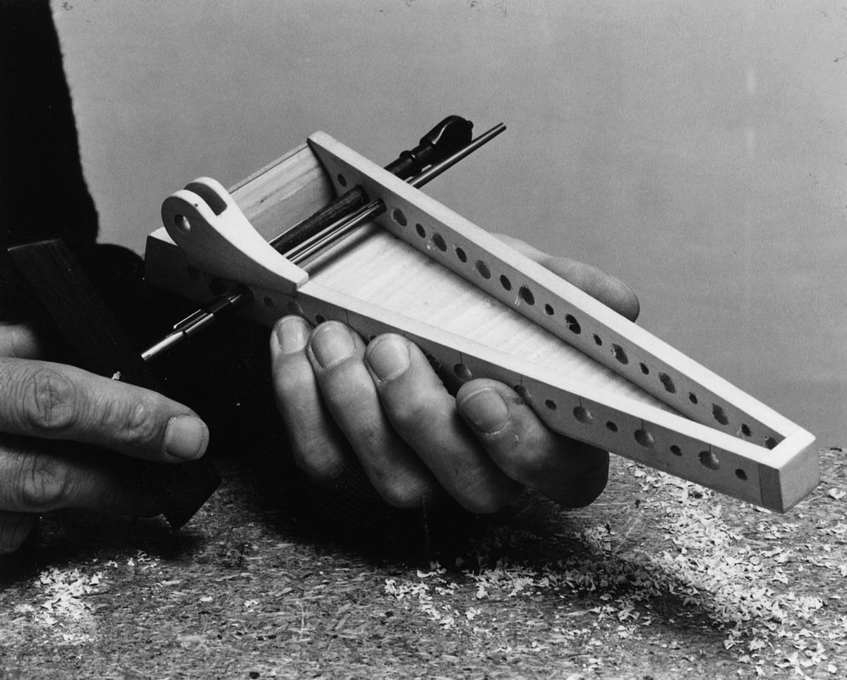


PHOTO 102, 103
PHOTO 104, 105


Pressure during glueing of the pegbox to the neck and the protruding fingerboard was achieved by a screw which was taken away after setting of the glue (photo 106). The hole this created was filled with a maple dowell.
Photo 107 shows marking of the nut. The completed nut was not glued yet, to facilitate adjustment later on.
PHOTO 106, 107
Photo 108 shows how the pegs were fitted in their holes. The pegs were bought readymade but nevertheless needed adjustment to fit them with equal pressure in both holes.
After some first coats of clear lacquer on the entire instrument (except the fingerboard and the pegs which are not varnished at all) a parchment strip was glued to the edge of the shell (photo 109). After this, varnishing was completed.


PHOTO 109
7 | POSITIONING OF THE FRETS
Gut was used for the frets, using decreasing gauges in the direction of the high positions (from .9 to .65 millimeters).
To determine the positions of the frets, first measure the distance from the nut to the bridge. This is called the scale length, or string length. You now have to use a simple mathematical division sum to determine the positions of the frets along the fingerboard.
With the scale length determined, divide the distance by 1.059463. This will give you the position of the first fret from the nut (scale length minus the calculated distance). Next divide the calculated
distance by the same 1.059463 to determine the position of the second fret and so on.
Once the position of the frets has been established, now comes the tricky part. Take the length of the gut that you intend to use for the first fret. Wrap the gut around the neck, not at the first fret position, but slightly towards the nut and secure the ends together with a knot (photo 110). You should then be able to gently slide the gut into position and as the neck has a taper it should become tight around the neck when in the correct position. It may take several attempts before you start to get a feel for it. Continue up the neck in the same manner.

At last the strings were added (photo 111). I used nylon Pyramid strings and the following gauges appeared appropriate for a renaissance tuning:
g 45
d d 50 50
a a 60 60
f f 906M 906M
c c 1007 1007
G G 1012 1012
f F 45 1022
e E 50 1024
d D 55 1026
c C 809AC 1028
b B 905 1030


COLOPHON
© This is a publication of Uitgeverij Extravert.
Hans Vaatstra (1938 – 2024) wrote the text and built the lute that is shown in this book.
Photography: Hilde Vaatstra
Design: The Creative Rebels, Sabrina Raams
Print: handled by The Creative Rebels
The TransTec/Van Hessen-Addeson Foundation contributed financially to the production of this book.
Rotterdam, May 2024
ISBN 978 90 9038 574 7
In the seventeenth century, the lute was known as the king of instruments. This string instrument with its enchanting sound evolved from the Arab oud, arriving in Europe via Spain and Sicily in the Middle Ages. The lute is extremely versatile, suited not only to playing in ensembles, but also as an accompaniment to songs and for solo performances.
Guitar maker Hans Vaatstra came up with a plan to make himself a lute. After producing several successful examples, he decided to record his knowledge. In A Homemade Lute, he shows you how to build a lute step-by-step. Photographer Hilde Vaatstra recorded the whole process in images.
It makes for a fascinating story that will inspire enthusiastic makers to set to work and build themselves a lute. What’s more, A Homemade Lute is a visually stunning book that will take you on a creative journey of discovery. Hilde Vaatstra’s elegant, lucid black-and-white photos with their clean lines and beautiful compositions are works of art in themselves.
A Homemade Lute unites two worlds. It is an ode to the magic of creating – with light, hands and music. Both looking and listening. With the motto: ‘Even if I knew that tomorrow the world would go to pieces, I would still plant my apple tree today.’