ISBN 978-1-909594-81-4
Published in 2019 by BM TRADA
While every effort is made to ensure the accuracy of the advice given, the company cannot accept liability for loss or damage arising from the information supplied. The opinions expressed by contributors do not necessarily represent or reflect the views of TRADA or the publisher.
All rights reserved. No part of this publication may be reproduced, stored in a retrieval system, or transmitted in any form, by any means, electronic, mechanical, photocopying, recording or otherwise, without the prior permission of the copyright owners.
© 2019 Warringtonfire Testing and Certification Limited
Prepared by Robert Hairstans, with the assistance of the BM TRADA publishing team
Layout by Academic and Technical Typesetting
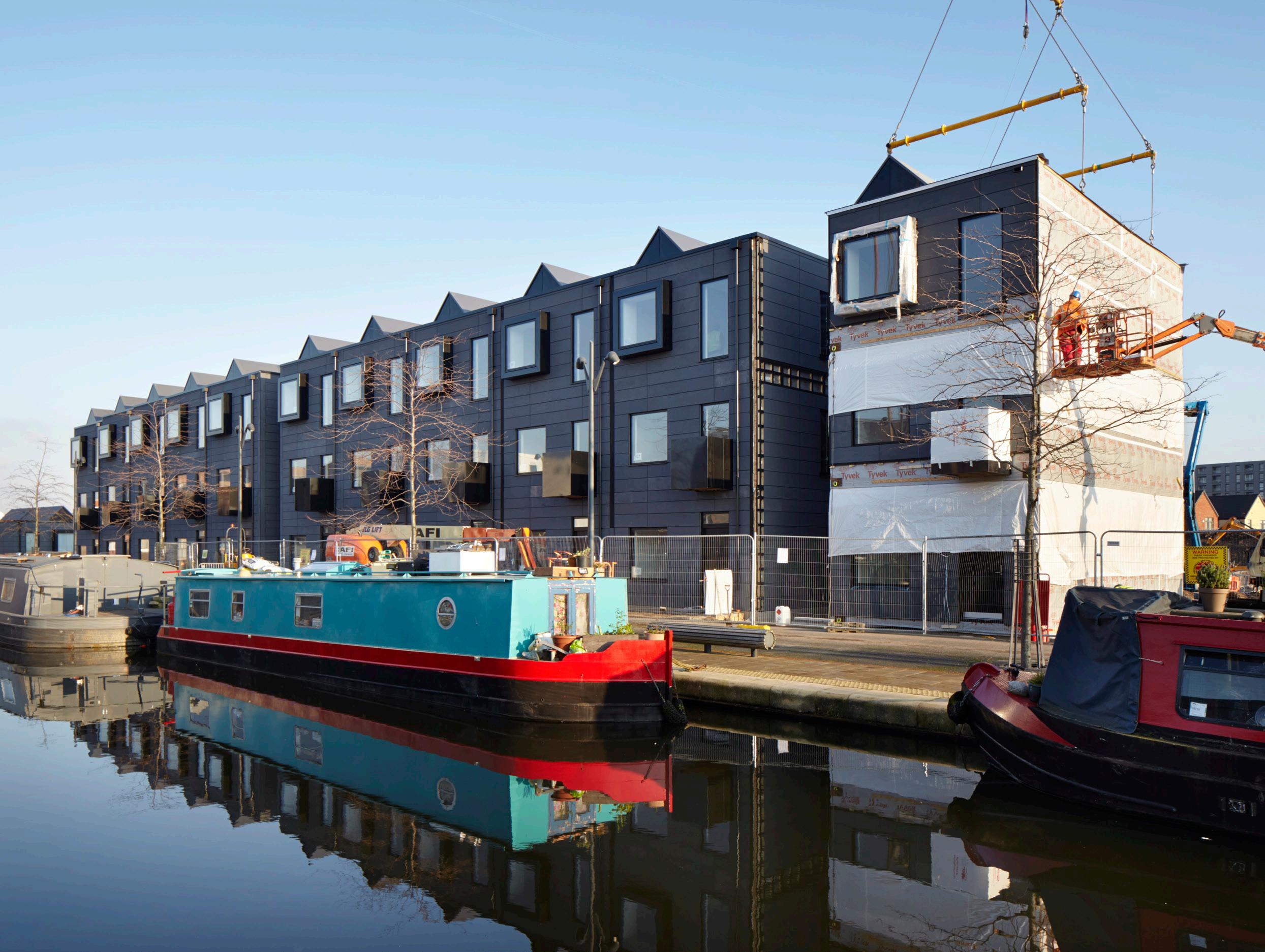
Cover photograph: New Islington © Jack Hobhouse
All other photographs and illustrations are © Warringtonfire Testing and Certification Limited unless otherwise credited
BM TRADA
Chiltern House
Stocking Lane
Hughenden Valley
High Wycombe
Buckinghamshire HP14 4ND
tel: +44 (0)1494 569600
email: publications@bmtrada.co.uk
website: www.bmtrada.com
Contents
1 Introduction
2 Off-site construction and pre-manufacture
3 Industrialisation of timber construction
4 Design
5 Production and construction
6 Timber technologies and systems
7 Case studies
Appendices
Bibliography
Note: the following pages are representative only, and have been taken from different sections of the book
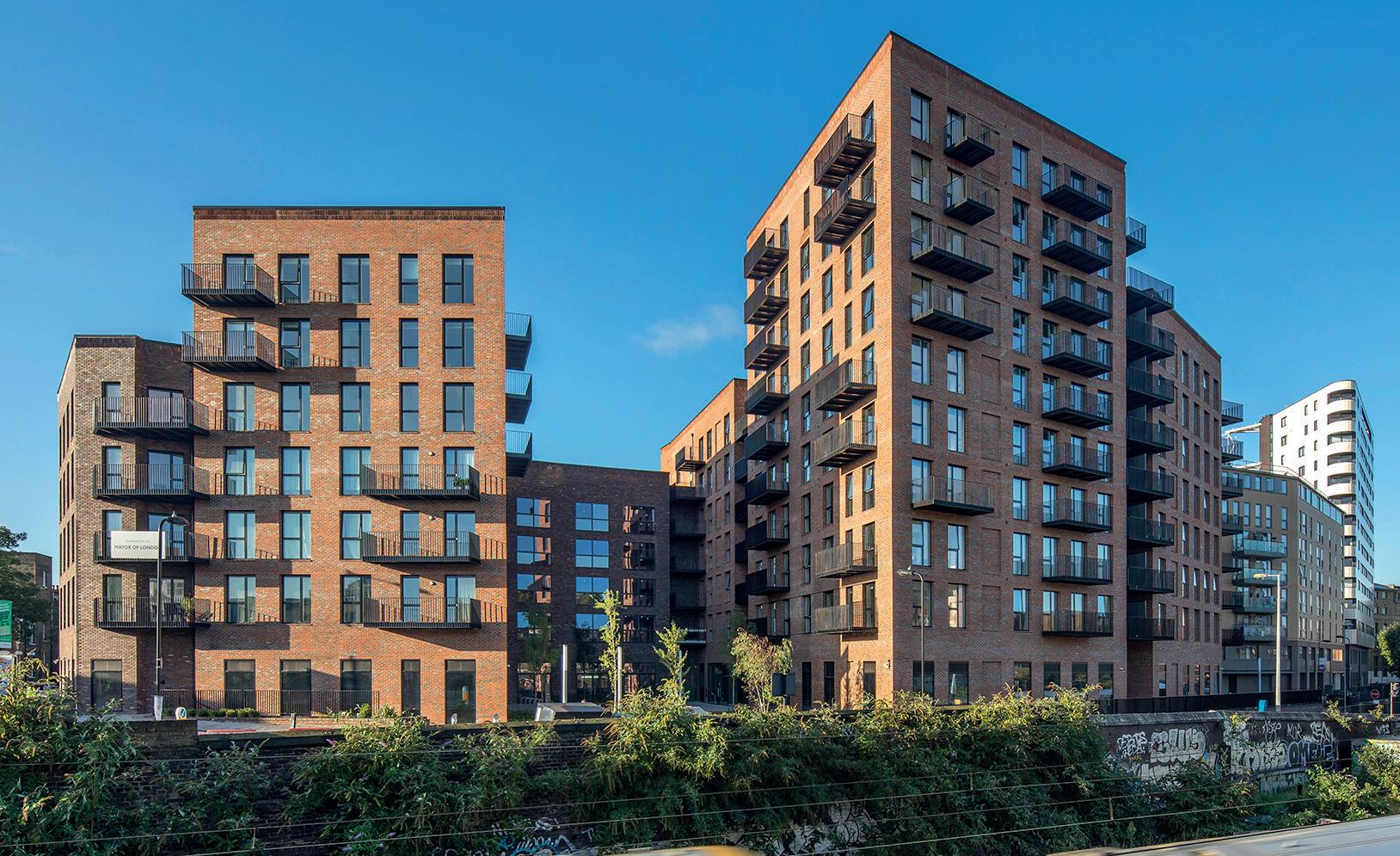
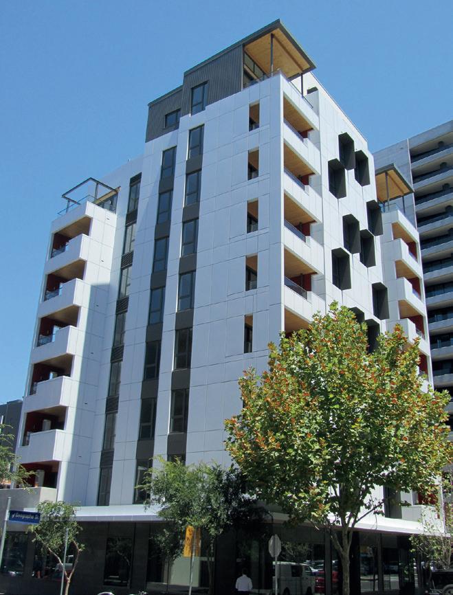
Lendlease (Figure 3.23). Forte Living claims to be the country’s ‘greenest’ apartment complex, reducing carbon emissions by 1,400 tonnes by means of replacing steel and concrete.[22] However, the tallest timber buildings, and those proposed going forward, will be of hybrid form (see Section 3.8). The Council on Tall Buildings and Urban Habitat (CTBUH) has a formed a Tall Timber Working Group (www.ctbuh.org/group-details/?group=25), with the objective of developing research activities to better understand the use of timber in tall buildings in order to create the first 40-storey building constructed with structural timber elements (see Section 3.9).
3.6 Large-section framing / sub-assemblies
Large-section timber framing has evolved through:
• timber engineered and composite products for post-and-beam framing
• innovative modern connection systems
• computer numerical controlled (CNC) automated machinery for the production of components and joints of high precision and tolerance (Figure 3.24).
There are many examples of this type of construction often forming open living spaces such as the small 80 sq m two-story house type developed for Japanese brand Muji by Kengo Kuma, a renowned Japanese architect and professor in the Department of Architecture at the University of Tokyo. These systems are pre-cut and assembled on site, and are therefore not officially known as ‘prefabricated’ in Japan, which accounts for approximately 15% of housing starts. Prefabricators must conform to the Japan Prefabricated Construction Suppliers and Manufacturers Association (JPCSMA), and to do so they must produce at least 300 homes per year. If pre-cut lumber kits and smaller-scale ‘house-makers’ (the Japanese term for companies building off-site homes) were considered to be prefabricated, off-site constructed housing would account for 25% of the detached home market in Japan.[23]
This style of framing using either solid section timber or engineered timber products is also used in Germany and Austria, where post-and-beam structural frames are combined with highly insulated wall panels. The houses are considered to be of ‘chalet’ design, but other forms are marketed, and there is considerable variety and flexibility in external features. Typical houses in Germany that use this type of construction have open living areas, large areas of glazing, basements, and the fitting and final finishes are invariably of a high quality such as those made by widely regarded Huf Haus. Formed in 1912 but shifting its expertise to create this type of post and beam (fachwerkhaus) in 1972, Huf Haus has since expanded to a 400-plus staff operation shipping internationally (Figure 3.25).


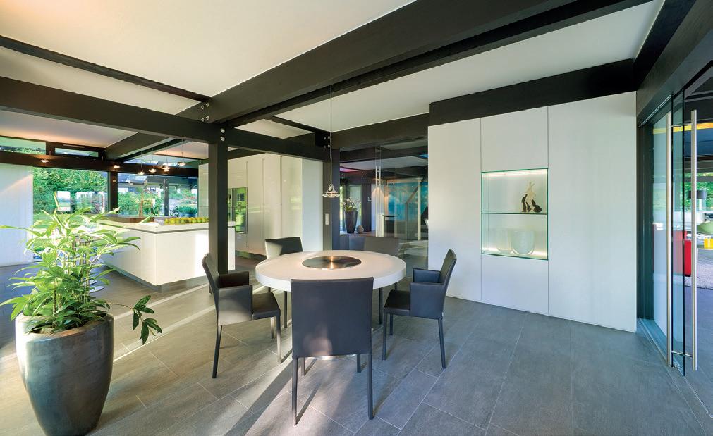
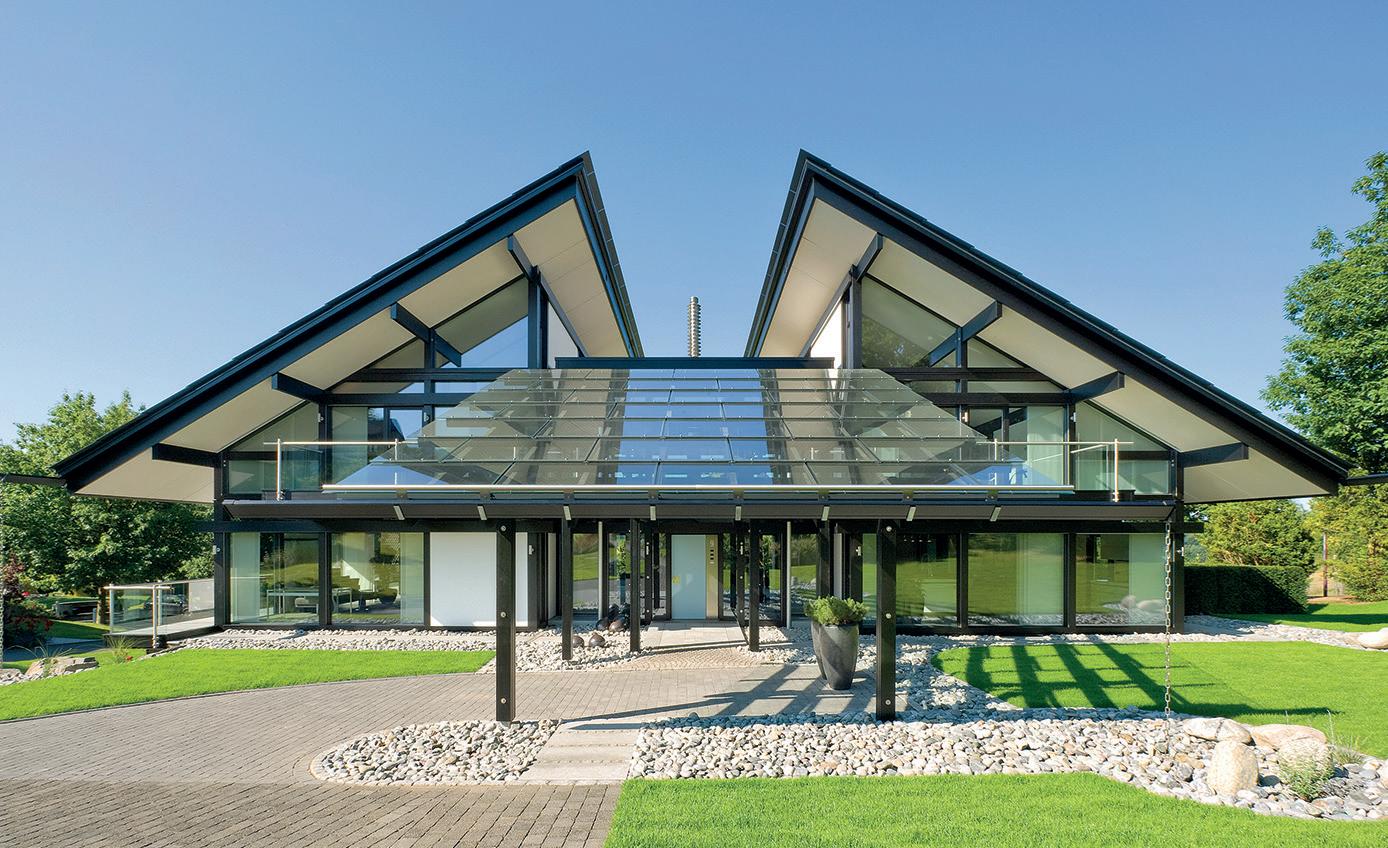
Figure 3.24

Figure title
Photograph
Credit
Figure 3.25
Figure title
Photograph
Credit

be given to road haulage constraints (Figure 4.9), the sequencing of on-site activities and method of manoeuvring the off-site components on site.
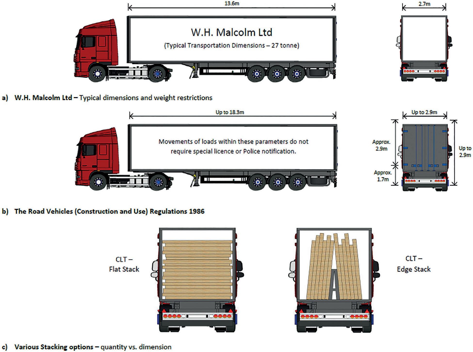
Key on-site considerations include:
• the allowable crane reach, if one is being deployed
• the available access for the components being brought to site
• the lifting equipment and where it should be situated (Figure 4.10).
It is also important to assess the transportation and construction methods to be used since the applied actions during these processes will be different from those that are applied in service. The system therefore requires a suitably robust design, often with lifting straps or lifting points inbuilt during the fabrication process, to be combined with an on-site lifting plan and method statement for safety while also ensuring serviceability criteria are not breached (see Section 4.4.1).
One advantage of timber is its strength-to-weight ratio; it is relatively light weight to manoeuvre resulting in a reduced carbon impact when being transported and providing more on-site flexibility for crane positioning. A fixed position crane can, for example, service numerous plots reducing set-up time.
4.3 Regulatory frameworks, standards and assessment processes
As explained in Chapter 3, timber forms of construction have evolved over the centuries as a result of material innovation, mechanisation and the need for improved levels of service life performance. Regulatory requirements
The level of automation (LoA) in manufacturing ranges from totally manual to totally automatic, with different levels of physical and cognitive intervention between humans and technology (see Table 5.3).[17] The LoA and use of robotics has the opportunity to revolutionise entire industries such as the home construction industry so as to reduce the cost and improve the quality
Level of automation
LoA Mechanical and equipment
1 Totally manual – Totally manual work, no tools are used, only the user’s own muscle power.
2 Static hand tool – Manual work with support of static tool, eg screwdriver.
3 Flexible hand tool – Manual work with support of flexible tool, eg adjustable spanner.
4 Automated hand tool – Manual work with support of automated tool, eg hydraulic bolt driver.
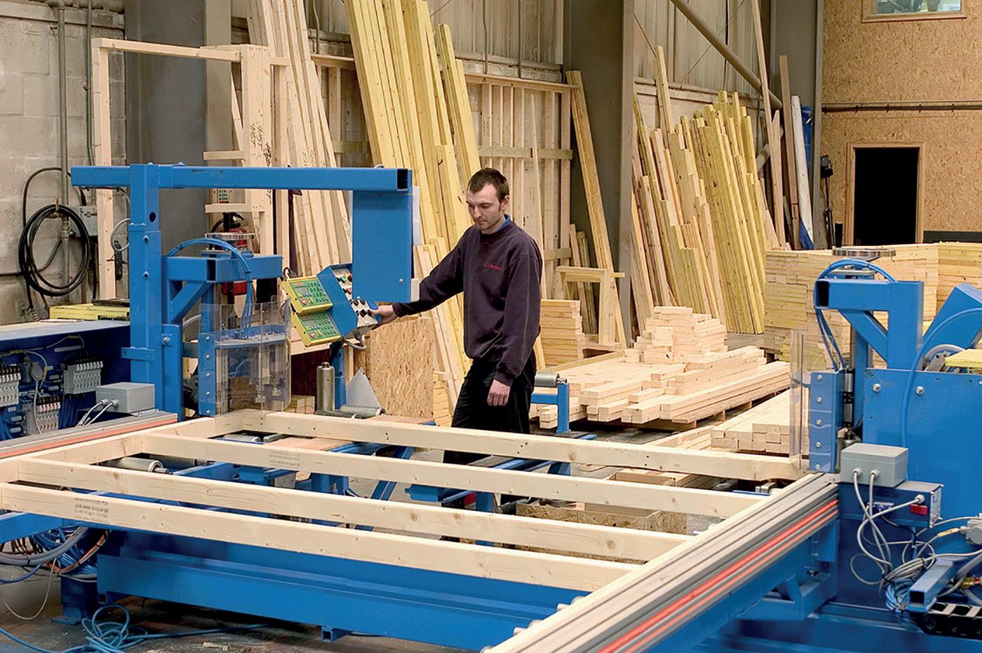
5 Static machine/workstation – Automatic work by machine that is designed for a specific task, eg lathe.
6 Flexible machine/workstation – Automatic work by machine that can be reconfigured for different tasks, eg CNC-machine.
7 Totally automatic – Totally automatic work, the machine solves all deviations or problems that occur by itself, eg autonomous systems.
Information and control
Totally manual – The user creates their own understanding of the situation, and develops their course of action based on their earlier experience and knowledge.
Decision giving – The user gets information on what to do, or a proposal on how the task can be achieved, eg work order.
Teaching – The user gets instruction on how the task can be achieved, eg checklists, manuals.
Questioning – The technology questions the execution if the execution deviates from what the technology considers as suitable, eg verification before action.
Supervision – Technology calls for the user’s attention and directs it to the present task, eg alarms.
Intervene – Technology takes over and corrects the action if the executions deviate from what the technology considers as suitable, eg thermostat.
Totally automatic – All information and control is handled by the technology. The user is never involved, eg autonomous systems.


