


Published
2024
by Waugh Thistleton Architects
© Waugh Thistleton Architects (2024) all rights reserved.
ACKNOWLEDGEMENTS
This guide has been developed as part of the Build-in-Wood project that recieved funding from the European Union’s Horizon 2020 research and innovation programme under grant agreement no. 862820
DISCLAIMER
This publication is provided for information purposes only. The views expressed are those of Waugh Thistleton Architects and other Build-in-Wood consortium contributors. Waugh Thistleton Architects and the Build-in-Wood consortium does not accept any responsibility for the contents or any loss, damage or injury which might occur as a result of following or using data or advice given in this publication.
Anyone using this guide must satisfy themselves regarding the application of statutory requirements, local building regulations, codes, insurance certification or other requirements or recommendations relevant to the location where they plan to build.
To the maximum extent permitted by applicable law, Waugh Thistleton Architects and the Build-in-Wood consortium disclaims all representations or warranties – express, implied, statutory, or otherwise – including (but not limited to) implied warranties of fitness for a particular purpose, accuracy or validity or completeness of information, merchantability, title, quality, and non-infringement. You assume full responsibility for any loss resulting from use of or inability to use the information, data, or advice in this guidance.
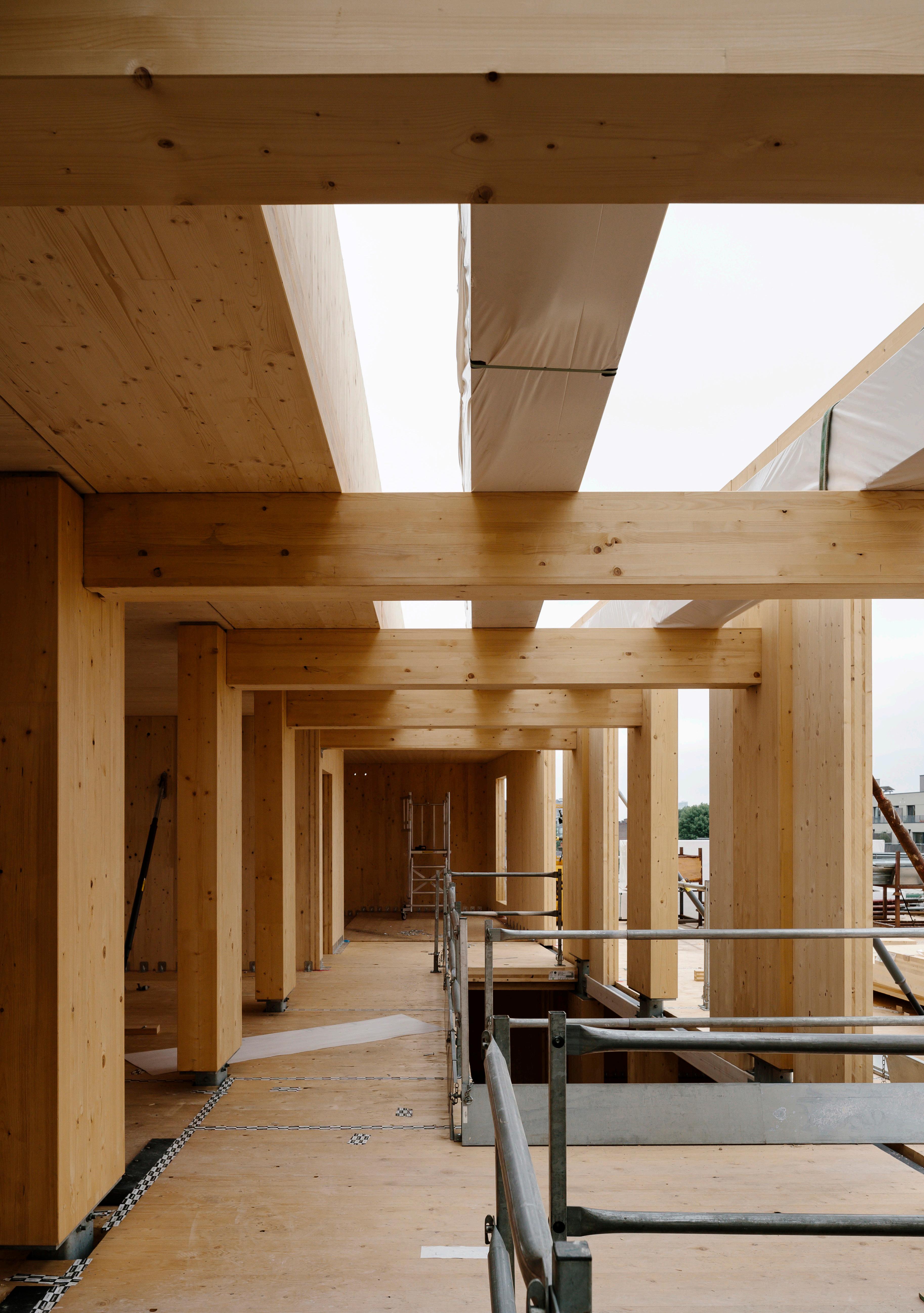
This booklet outlines the key assembly steps for installation of the Build-in-Wood structure and façade systems. Assembly details are also provided for key interfaces, demonstrating the primary components and mechanical connectors that are used to join components at each step of the assembly process. Most connectors and products shown are widely available on the market from various manufacturers.
The use of steel connections is common practice in timber construction. The Build-in-Wood system focuses on the use of a minimal number of pre-existing certified connectors, clarifying and illustrating how these products can be used in different scenarios.
Alongside the use of standard available products a Build-in-Wood project partner has developed two connectors which follow the same principles as other standard products but are uniquely tailored to meet the needs and aims of the Build-inWood system. The first, a connector for the beam to column interface, typically one of the more challenging and yet most prevalent connections in an engineered timber structure; and the second, a simple angle bracket for installation of the façade system onto the structure. Using simple, easy to install and materially efficient connectors has the potential to offer not only carbon - but also cost - savings on an engineered timber project.
Each detail has considered different solutions for providing fire resistance to the steel connectors, either through gypsum linings and encapsulation or through embedding of the connections within the timber components themselves. The latter is more appropriate where it is intended for the primary structure to be visually exposed.
LOCATION
DETAILS
LOCATION
3 - Beam assembly
DETAILS Detail 5 - Beam to core connection
4 - Beam to column connection
2.4 STEP 4
SUBSEQUENT STOREY
LOCATION
DETAILS
Detail 9 - Column to column (node)
LOCATION
DETAILS
Detail 10 - Facade panel to structure
Detail 11 - Facade panel to panel
LOCATION
COMPONENTS
Steel column base on threaded bar with double nut and self expanding mortar
Raised access floor system
Screwed angle brackets
COLUMN BASE - GROUND FLOOR
To increase the durability of timber column bases, it is common practice to raise them a minimum of 150 mm from the surface of the ground level slab (typically reinforced concrete). The system proposes the use of custom-made steel post bases: a connection that deals with the compression forces and loads generated by the structure above. The steel column base then needs to be intumescent painted or encased within concrete for fire-protection
COLUMN BASE - PODIUM
For projects where the timber structure begins significantly above the ground floor level (e.g., at first floor), screwed angle brackets constitute a valid alternative to the steel post base and may in circumstances offer cost savings. Steel shims can be used as spacers to level the substrate before landing the column; a bituminous membrane must also be installed under the column’s footprint to prevent moisture damage. A similar approach informs the timber floor slab to column connections on subsequent floors, as the columns are expected to take vertical loads only.
COMPONENTS
Hold-down bracket
Angle bracket (screwed)
Angle bracket (screwed) + special base plate
Line of raised floor level
Plasterboard lining
Hold-down brackets (A) deal with vertical tension forces, whilst angle brackets (B) deal with horizontal shear forces. As connector type As can be visually impactful, they are used primarily where CLT walls are hidden behind plasterboard lining.. As with the column base details, CLT walls that are at ground level should be raised a minimum of 150mm above the level of the slab to help safeguard against moisture issues. This can be achieved through the introduction of a concrete upstand to support both the wall itself and its connectors.
WALL BASE - EXPOSED
If the architectural intent is to expose the CLT walls, screwed angle brackets with special (thicker) baseplates can be used to deal with tension forces and avoid the need for visually obtrusive hold-down brackets.
BEAM ASSEMBLY
LOCATION
COMPONENTS
Single glulam section (max. 240mm width)
Countersunk wood screw (45 deg. angle)
Glued surface
DOUBLE BEAM - SCREWED CONNECTION
The maximum width of standard sized glulam beams is 240 mm. If wider sections are required then standard sections must be joined together. A series of inclined screws is commonly used - in conjunction with glue - to mechanically fix two or more standard sections together so that they work compositely.
DOUBLE BEAM - GLUED CONNECTION
Block-gluing of standard sized beams is an alternative production method for large glulam sections, however the number of manufacturers who are currently able to certify this production procedure is limited.
max. 240 mm
max. 240 mm
BEAM TO COLUMN
LOCATION
COMPONENTS
Hook shaped connector (recessed / concealed)
Hook shaped connector (non-recessed /exposed)
Primary beam
Service beam
Connection fire protection area
Plasterboard encapsulation
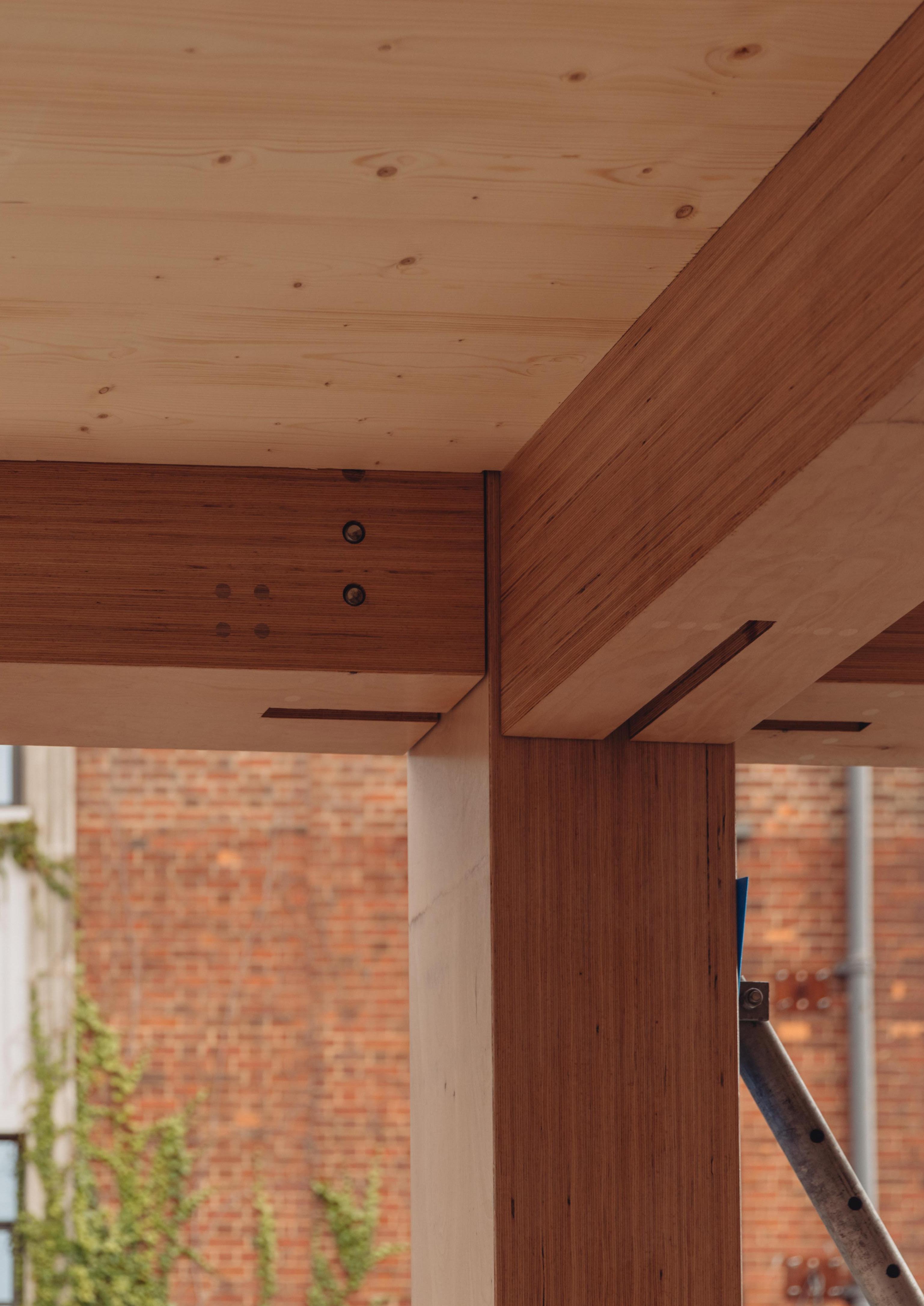
BEAM TO COLUMN CONNECTION - EXPOSED
The column to beam connection is achieved by vertically sliding the hook shaped connectors (which are pre-installed into the relevant face of the column and beam respectively) into one an another. This approach allows for vertical axial (column inclination/beam length) and lateral tolerances. Furthermore, there is no need for additional on-site assembly operations as all connectors can be installed off-site.
BEAM TO COLUMN CONNECTION - CONCEALED
Connections need to be constructed with a fire-resistance equal to that of the connecting members. Depending on whether the structure is exposed or encapsulated, the connector can be concealed and protected by a sacrificial layer of timber, or left exposed to rely on the protection of a plasterboard lining (as illustrated).

* The load scenarios for all beam-to-column connections for the system were reviewed in collaboration with Built-in-Wood partner Rothoblaas. The structural capacity of the existing Lock T connector is sufficient for the lower loads (such as those of the façade / perimeter beams), whereas the primary spanning beams required a more substantial connector - leading to the development of the Alumega product that is now on the market.
Visit the Rothoblaas website at www.rothblaas.com to learn more.
LOCATION
COMPONENTS
Perimeter beam
Core wall (CLT)
Hook shaped connectors with horizontal screws
Fire protection area (exposed walls)
Core wall (RC concrete)
Recess into RC concrete wall
Steel plates
This connection proposes use of the same connector developed for the column and beam interface. Here, the column mounted part of the hooked connector instead located on the CLT core wall. The connector can be concealed and protected by a sacrificial layer of timber or left exposed to rely on protection via a plasterboard lining. The routed detail is best suited for single storey CLT core walls; it can also be used in multistorey wall configurations provided the carveout in the CLT wall is designed to allow for the top-down movement of the beam positioning process.
Alternatively, timber beams can be supported from recesses created within reinforced concrete core walls. These beams do not require fixing to the concrete wall, as the angle brackets that link the CLT slab edges to the core-walls provide a sufficient connection. Steel plates are used as levelling devices as the allowed tolerance for RC walls are much larger (20 mm) than those permitted for timber construction (2-3 mm). It may be necessary to purposefully oversize the recesses within the concrete walls to ensure that the tolerance can be dealt with via steel shims irrespective irrespective of the tolerance being positive or negative.
LOCATION
COMPONENTS
Service beam
Primary beam
Timber battens (temporary propping only)
Angled fasteners arranged in a screw cross
In this configuration, the CLT slabs sit within the depth os the beams, supported from the sides of the beams, as opposed to spanning across the top of the beams. This approach reduces the structural depth and subsequent impact on head height, but prevents the use of CLT slabs that span multiple bays, which can themselves be materially optimised due to the superior structural configuration. It may be prudent to investigate the implications of this alternative beam and slab configuration dependent on project specific aims.
Here, the double beams to the primary bays are notched to the outside to receive the slab. This allows the slab to bear onto the beam working in combination with the screwed connections.
In service bays where the beams are predominantly single, the use of a timber batten enables temporary propping of the slab edge whilst the screws are installed. This timber batten can be pre-assembled onto the beam prior to installation (either off or on-site).
Floor Slab to Single Beam - During Assembly & Assembled
FLOOR SLAB TO FLOOR SLAB
LOCATION
COMPONENTS
Vertical self-tapping screws
Plywood strip
45 deg. inclined screws
FLOOR SLAB TO FLOOR SLAB - HALF-LAPPED JOINT
Possibly the most common type of slab to slab connection, a half-lapped joint has good fire performance (smoke and heat transfer), both panels need to be shaped to form the half-lap, which in turn reduces the net-area of each panel.
FLOOR SLAB TO FLOOR SLAB - SINGLE SURFACE SPLINE
Surface spline connections are made using plywood strips, which are placed into a routed section situated along the floor panel joints. These type of connections require machining of the panel edges, however there is less material loss and no net-area loss compared to half-lapped joints. Good fire performance (especially in terms of heat transfer) is provided when intumescent seals/tapes are installed along the slab joint.
FLOOR SLAB TO FLOOR SLAB - PLANE JOINT WITH CROSSED SCREWS
A simple, plane joint connection is the most cost-effective method of transferring shear forces between CLT panels. Screws are installed at a 45° angle to the floor panel edge, creating a connection for a minimum of half the panel’s thickness. However, the plane joint connection’s fire performance is not comparable to those achieved by half-lap and spline connections without additional measures.
High horizontal force connection
Screws to floor panels for vertical forces
Timber battens (temporary propping only)
Line of raised floor level
CLT floor plate spanning perpendicular to wall
CLT core wall (single or multi storey)
Here, the angle bracket connection is positioned above the floor plate: a configuration that allows the bracket to be fireprotected by the floor build-up above (or other means such as intumescent paint), whilst also allowing the soffit of the floor slab and the CLT core wall to be completely exposed if desired.
Timber battens are often used for temporary propping whilst the screws are connected through the angle brackets.
This same detail can be used when installing CLT slabs against reinforced concrete core walls, however the difference in tolerance between CLT and concrete must be considered, and it may be necessary for additional fire stopping to be provided between the two surfaces.
Slab to Core - Assembled
LOCATION
COMPONENTS
COLUMN TO COLUMN (NODE)
This detail represents the combination of details 1, 3, 4 and 6, which coincide at the connection between columns of adjacent floors of a building. Here, the column to the levels above is installed in accordance with the column base installation (above ground) utilising a combination of angle brackets connecting to adjacent beams and slabs, as well as direct bearing on the column beneath. In some project specific circumstances, a direct column to column connector may also be required.
Column to Column (Node) - During Assembly
Column to Column (Node) - Assembled
LOCATION
COMPONENTS
Facade bracket
Angled fasteners arranged in a screw cross (45 deg.) along slab / perimeter column edge
Perimeter beam Angle bracket connections on 3 sides of perimeter columns
The facade panels are mounted to the structural frame via a series of angle brackets that connect both the head of the lower panel and base of the upper panel at low level from within the floorplate of the building.
The angle bracket is designed with a series of holes and slots to enable the position of the panels to be adjusted according to any tolerances, ensuring the precise alignment necessary for a pre-clad facade system.
The brackets are 0.5m long, typically requiring installation at 1m spacing, but this must be adjusted accordingly to enable additional structural connectors at column locations and where full height openings require brackets to be omitted.
LOCATION
COMPONENTS
Angle bracket
Vapour control layer
Intumescent cavity barrier
Cement board
Rainscreen cladding
Perimeter beam
Adjacent facade panels do not need to be structurally connected to each other, as they are independently supported from the main building structure. However, panel interfaces have been carefully designed to enable continuity of different performance criteria to be achieved between panels.
Internally, a zone has been designated to allow the vapour control layer to be lapped and sealed along all horizontal and vertical panel interfaces. It is also essential for the plasterboard linings to be infilled (where gaps have been left to enable sealing of the VCL), taped and sealed in line with manufacturers requirements to ensure that the fire performance is achieved.
A compressible insulative product should be included around the entire perimeter of the panels to prevent cold bridging between adjacent panels. Continuity of the external, breathable weather tightness layer can either be sealed manually (in scenarios where cladding is mounted on site and access can be gained to this location from the building exterior), or can make use of a self-sealing joint between panels, a concept for which has been developed by the consortium.
This approach is predicated on the use of breathable membranes lapped from the front face of the cementitious board over the edges of the panel where a self-expanding seal is positioned, which will form a seal between the lapped membranes of two adjacent panels when they are brought together. This detail is challenging to execute and must be verified based on the specific panel tolerances and other relevant factors on any given project. If this approach is taken, it is recommended that panels are offset between subsequent building stories to prevent this self-sealing detail being attempted at the interface of four corners, where it will be particularly difficult to coordinate.