


Published
2024 by
Waugh Thistleton Architects
© Waugh Thistleton Architects (2024) all rights reserved.
ACKNOWLEDGEMENTS
This guide has been developed as part of the Build-in-Wood project that recieved funding from the European Union’s Horizon 2020 research and innovation programme under grant agreement no. 862820.
DISCLAIMER
This publication is provided for information purposes only. The views expressed are those of Waugh Thistleton Architects and other Build-in-Wood consortium contributors. Waugh Thistleton Architects and the Build-in-Wood consortium does not accept any responsibility for the contents or any loss, damage or injury which might occur as a result of following or using data or advice given in this publication.
Anyone using this guide must satisfy themselves regarding the application of statutory requirements, local building regulations, codes, insurance certification or other requirements or recommendations relevant to the location where they plan to build.
To the maximum extent permitted by applicable law, Waugh Thistleton Architects and the Build-in-Wood consortium disclaims all representations or warranties – express, implied, statutory, or otherwise – including (but not limited to) implied warranties of fitness for a particular purpose, accuracy or validity or completeness of information, merchantability, title, quality, and non-infringement. You assume full responsibility for any loss resulting from use of or inability to use the information, data, or advice in this guidance.
In the context of the urgency of the current climate crisis, the EU has committed, under the Paris Agreement, to become carbon neutral by 2050. To meet this target, serious disruption of ‘business as usual’ is required in many sectors, construction included.
With improvements in thermal fabric and operational energy having been the target of sustainability agendas in recent history, the significance of embodied carbon is increasing and subsequently moving to the forefront of political conversations.
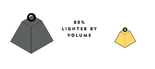
Building with wood can drastically reduce the embodied carbon associated with traditional building methods like steel and concrete. Not only is timber far less carbon intensive than these materials, but it also stores biogenic carbon absorbed during the life of the trees.
Harvesting timber from sustainably managed forests, where replanting maintains, if not increases, timber volumes year on year, allows timber buildings to become a new carbon sink. This means building in wood not only reduces the direct carbon emissions of construction but can reverse current carbon levels through increased sequestration into a ‘new carbon store’.
By engaging with stakeholders across all sectors of the timber value chain, the Build-in-Wood system has been designed to optimise the use of the forest resources available, on the basis that efficient use of timber will enable the greatest positive environmental impact.
The carefully designed and tested solutions of the Buildin-Wood system provide the confidence that any given project, irrespective of specific requirements, can be built in timber - and the knowledge and expertise needed to do just that!


The Build-in-Wood system aims not only to minimise as far as possible the negative environmental impact of construction, but also to actively remove carbon from the atmosphere through sequestration. business as usual


AND THE PARIS AGREEMENT
Build-in-Wood is an optimised timber building system designed for maximum adaptability. The system can be tailored to meet a variety of drastically different building requirements, without the inherent redundancy that can often result from a system designed for multiple scenarios.
The system incorporates a structural frame and a nonstructural façade, which have been designed for use holistically as well as independently to encourage reuse, retrofitting and extensions of existing building stock.
Different project specific requirements, such as building use, location, performance requirements and aesthetic aspirations are accommodated through selection from a refined spectrum of iterative components within the system kit-of-parts.
This focus on achieving the necessary adaptability through variable, rather than fixed components (resilient to all requirements), ensures a tailored solution for each project that is materially, environmentally and financially viable and efficient.
The system is designed for longevity, taking into consideration a building’s eventual disassembly and end of life use to effectively maximise the lifespan of each timber component, subsequently extending the period for which it can store biogenic carbon.
The system aims to increase awareness and understanding of the significance that lifespan has on the potential of timber products to act as carbon stores. It does this by designing to promote adaptability of the building itself as well as the demountability and re-use of its components – both of which help to maximise the useful life of the material before it is allowed to decay or burn, re-releasing its carbon.
The structural and façade systems are designed to work in harmony, however can also be used independently to further increase the applicability of the systems.
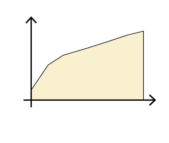
A small spectrum of components designed to a range of criteria
Figure: Caption needed
(through redundancy)
Single components designed to most onerous criteria
The Build-in-Wood system consists of a kit of variable components, which can be tailored to achieve the range of performance criteria typically required for residential or commercial buildings of between five and ten stories across Europe.
This document details the key features of the system and rationale behind it’s design, whilst also guiding the reader towards other publications to support their understanding of design and construction with timber. This initial outline document is supported by the following supplementary booklets:
– Component Selector – Assembly Manual
The component selector is a catalogue of the range of components designed for each aspect of both the structural and façade systems. The components are selected dependent on key design parameters (for example beam sizes are dependent on building grid), or in some scenarios dictated by project performance and/or aesthetic requirements or drivers.
Assumptions are clearly stated to allow design teams to verify whether the scope of the solutions developed for Build-in-Wood aligns to their project requirements.
Advice is also provided throughout to help the user design with wood, other bio/based materials, and pre-fabrication in mind.
This advice hopes to facilitate parameters of the design, which are not pre-set by local legislation, to be tailored to optimise the potential use of timber with focus on a projects own specific aspirations and goals.
Once the components required have been defined, this subsequent section provides advice on assembling these components, showing the key interfaces and connections which have been designed for the Build-in-Wood system.
Simple axonometric diagrams show how the components come together illustrating the type and number of connectors required, and how this assembly varies based on certain key project criteria, predominantly whether the timber structure is to be exposed or concealed.
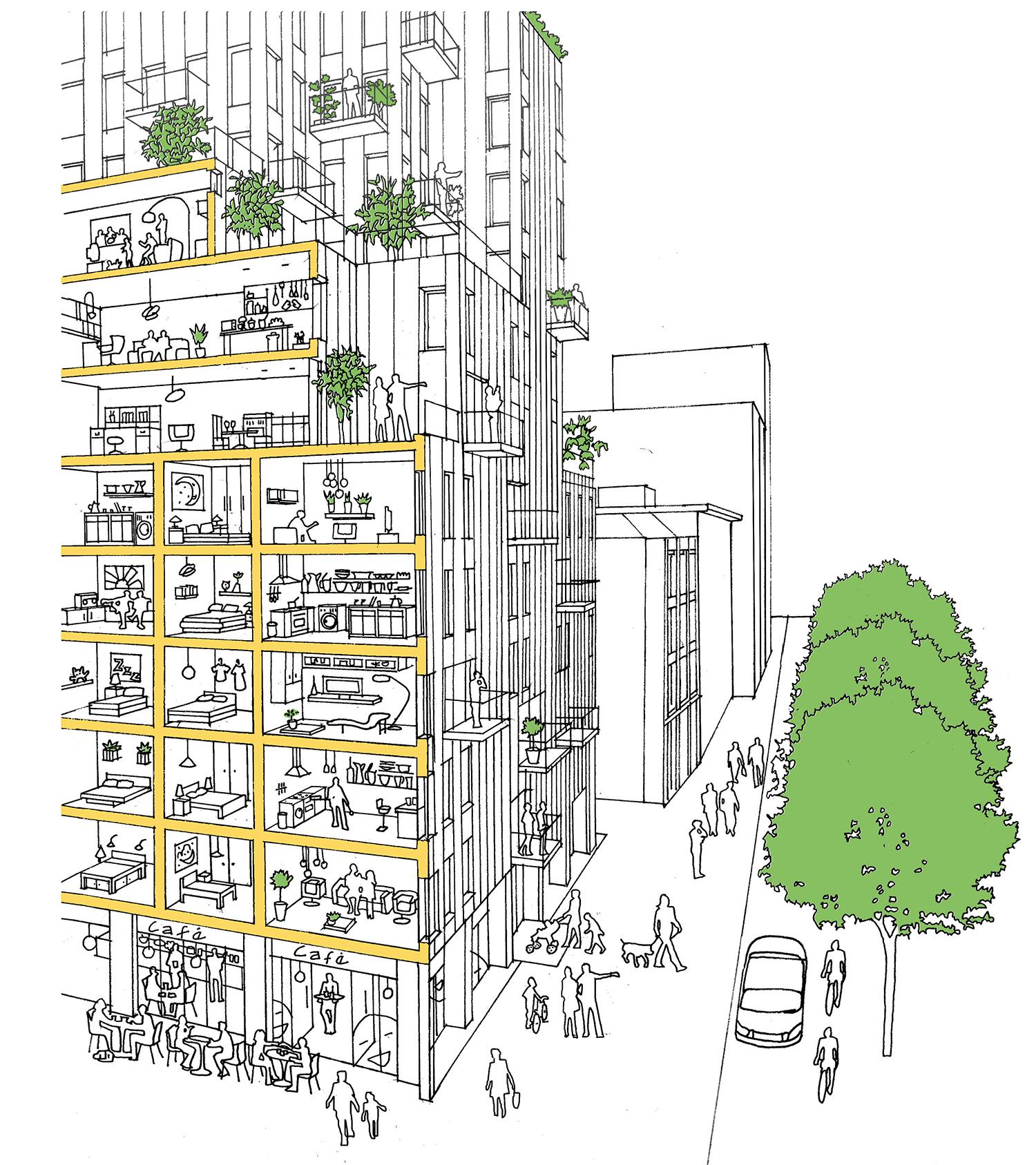
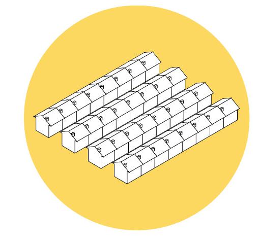
A future city built using the Build-in-Wood systems
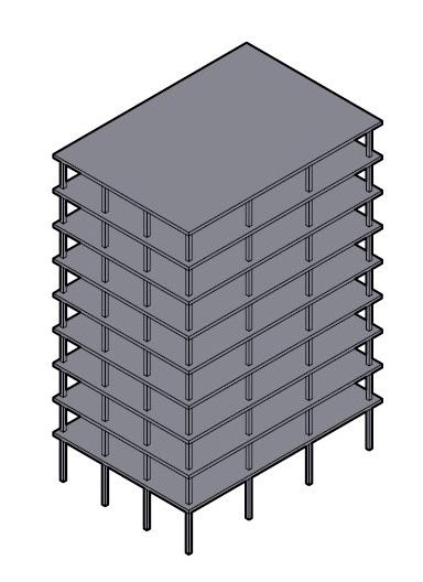
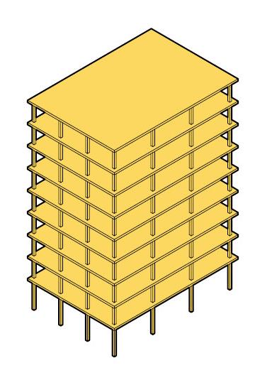
The Build-in-Wood structural system is designed as a post and beam frame, due both to the flexibility of internal configuration offered by this structural approach and its material efficiency, allowing more buildings to be constructed from the available timber.
Not only is flexibility of internal layout vital to design buildings with different functions, but this approach also offers the potential to reconfigure spaces to change or modify their use during or post construction, potentially extending the building’s useful life.
This future adaptability is particularly beneficial in the current post-pandemic context, with uncertainty surrounding future work habits. This flexibility can help guarantee longevity from an environmental perspective and for a client’s investment.
The main bay is designed as a flexible open space with perimeter columns only. The use of a hierarchical grid, which is a primary span greater than the secondary span, is most efficient structurally, offering both material and cost savings, with minimal impact on internal layout due to the flexibility already inherent within the ‘column free’ primary bay.
To maximise headroom, the system configuration has been developed with a clear servicing strategy. Primary beams are oriented perpendicular to the façade, spanning out from a central servicing corridor. The narrow width of this corridor reduces the beam depth in this location, enabling central service runs to be distributed across the length of the building without compromising headroom.
From this main spine, services are then distributed out into individual bays in between the primary beams, ensuring services can reach all areas of the building without needing to pass under the deep primary beams of the main bays.
This configuration allows rational distribution of highlevel services as well as creating a natural circulation and access zone, beneficial for both residential and office layouts.
Once defined, the ‘typical bay’ can be iterated in 3D to create different building forms. Using the bay as a ‘Lego’ block, this repeatable component can be arranged in infinite configurations.
A building’s core(s) can then either conform to the grid, occupying a bay or bays, or can sit outside the grid. The latter allows the core to become a vehicle by which the naturally rectilinear building form can be suited to the irregularities of a real-world site; connecting, infilling, and/or reorienting respective ‘blocks’.
With this understanding it is possible to consider how the simple geometry of the system can adapt to varied sites, whilst also providing the building’s stability and maintaining an efficient solution for much of the floor area. A larger irregular void can be filled with a more generous core, be that in the form of a courtyard, atrium or other space.
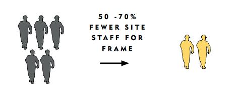
To align with the project ambitions of design for disassembly and improved end of life prospects, the solutions developed for the system have prioritised use of dry products and materials. Using materials that are dry installed rather than wet not only means that different layers and materials can be more easily taken apart and separated for reuse or recycling at the end of the building’s life, but also helps to contribute to a clean, safe installation process with fewer health concerns for the site workers erecting the building.
Alongside focus on dry materials and build-ups, the Buildin-Wood system has strived towards the use of mechanical rather than glued or ‘wet’ connections for the same goals.
Connections have been considered and developed for all key interfaces within the structural system. The use of steel for mechanical connectors is typically unavoidable in engineered timber buildings of this scale, due to the loads. However, simplifying the approach to these connections has the potential to offer not only carbon, but also cost savings.
The system uses predominantly simple, widely available and certified brackets and screws, also capitalising on bearing connections through notches and ledges that can be easily pre-routed into the relevant timber components. Fire protection has been considered for all connectors, whether exposed or concealed behind gypsum linings, and the timber itself is used to provide protection to steel connectors where possible.
Post + beam
Bay + service bay
Adaptive core
Layout flexibility & adaptability
Key:
Dry build-ups
Mechanical connections
Features
Drivers
Figure: Structural system key features and drivers
Layout flexibility & adaptability
Stability
Clean safe installation
Material efficiency
Services distribution
Site adaptability
Demountability & future re-use
Clean safe installation
Demountability & future re-use
As bay width is consistent through the primary and servicing bay, and the floor slabs do not support the façade panels, only a single slab type is needed for any given bay configuration.
Conversely, due to the differing structural loads/demands in various positions within the bay/building, the system incorporates 5 beam types:
– Primary Beam (primary spanning beam taking load from two slabs)
– Primary Edge Beam (primary spanning beam taking load from one slab and adjacent façade panel)
– Service Beam (service corridor spanning beam taking load from two slabs)
– Service Edge Beam (service corridor spanning beam taking load from one slab and adjacent façade panel)
– Façade Beam (beam spanning parallel to the floor slabs taking load from adjacent façade panel only)
Column sizes are influenced not only by the scale of the bay and consequently the primary and secondary spans (dictating the number of columns) but also by their location on the floor plate - internal, perimeter or corner - and by their position within the height of the building.
Higher up the building the total load distributed down through the columns is reduced and so column sizes can be respectively smaller in order to optimise material efficiency.
The Build-in-Wood system allows for the use of continuous multi-storey columns of up to 3 stories, therefore column sizes are provided for sets of between 2 and 4 stories for the different column types as follows:
– Internal Columns (taking load from adjoining primary and service beams and columns above)
– Size X (uppermost 3 stories - always used)
– Size Y (mid 3 stories - next used if required)
– Size Z (lowest 3 stories - final used if required)
– Perimeter Columns (taking load from adjoining primary and façade beams and columns above)
– Size X (uppermost 3 stories - always used)
– Size Y (mid 3 stories - next used if required)
– Size Z (lowest 3 stories - final used if required)
Although the loading scenario for corner columns (taking load from the adjoining primary edge and façade beams and columns above) differs slightly to that of perimeter columns, these two column types are often dimensioned the same for the purpose of standardisation. For this reason the Build-in-Wood system does not include unique sizes for corner columns, however the loading on corner columns can be reviewed on a case-by-case basis to explore the scale of possible material saving against the additional complexity of an additional column type.
5-6 STORIES
7-9 STORIES
10 STORIES
Column sizes vary according to the building’s height. Columns are larger at lower floors tapering up the building.
The load being carried is cumulative, so the top floor will have the same column size regardless of how many floors are beneath it.
The extent of, and demands on, the stability structure of a given project are largely influenced by the building’s size, geometry, and location.
The Build-in-Wood system anticipates that a building’s core or cores are the predominant mechanism for providing stability and shear capacity to the structure. However, dependent on the construction, location, size and number of cores, it may be necessary to introduce additional shear walls and/or bracing, which must be confirmed on a case-by-case basis. In general, the taller the building the more onerous the demands on the shear system; however, various other site-specific factors such as ground, wind and seismic conditions also have influence.
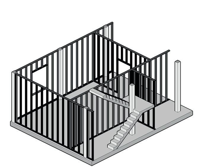
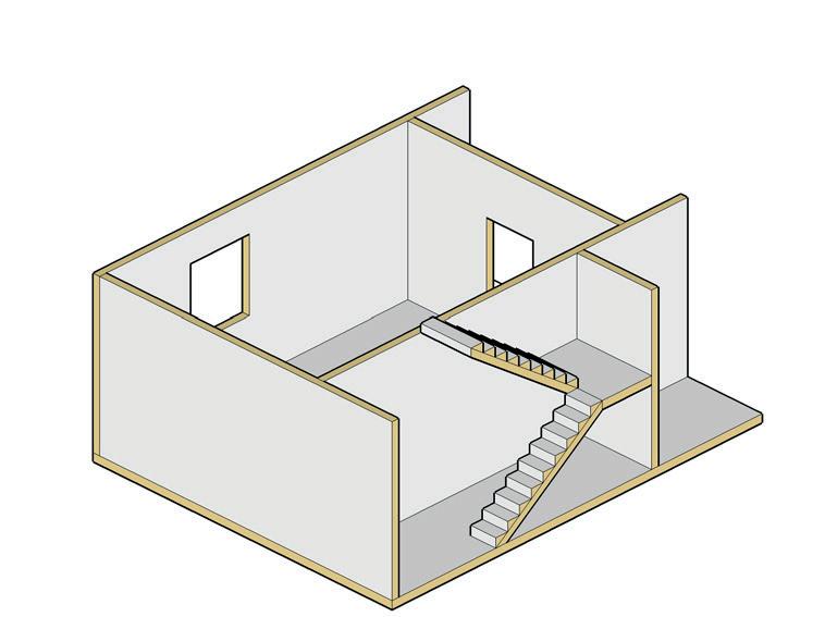
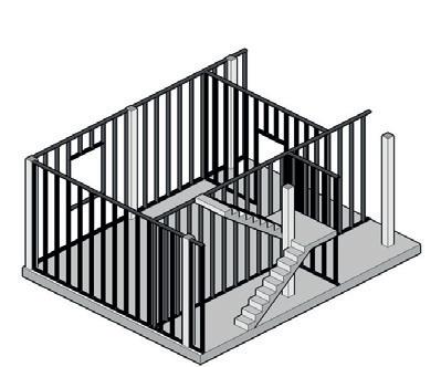
Fire regulations in several European countries specifically prohibit the use of combustible materials for the primary evacuation & egress routes in the event of a fire, meaning the stair cores cannot have an engineered timber structure. Accordingly, the Build-in-Wood system can accomodate different material options for a building’s core, predominantly either CLT or concrete.
Given the degree of possible variability in any given project’s design, the stability system must be uniquely developed by the design team to ensure it is suited to the individual circumstances and requirements. However, despite this individuality, the form of the core(s) have essentially two options for integration within the building system itself, in that it can either conform to the grid, occupying a bay or bays, or can sit outside of the grid.
By positioning the core outside of the building grid, the rectilinear building system can be adapted to suit different site geometries and architectural ambitions, without losing the the benefits and efficiency of the repeated components within the main bays.
With this understanding it is possible to consider how the simple geometry of the system can adapt to varied sites, whilst still providing the building’s stability, and maintaining an efficient solution for the floor area.
Connections between the main structural post and beam frame and CLT or concrete shear/core walls have been considered and are included within the Assembly Manual.
STRUCTURAL TIMBER CORE ON-GRID CONCRETE CORE
Core typologies
Historic timber buildings illustrate the potential for timber to match, if not exceed, the life span of conventional construction materials.
However, the key to ensuring longevity of timber is in preventing the moisture content from exceeding the factory level of around 12% for any extended period. Timber that gets wet will dry out if moisture source is quickly removed and adequate ventilation is provided, however the priority should be avoiding this scenario altogether.
Moisture management on site is critical for mass timber projects, the primary aim being to ensure the timber is not exposed to prolonged moisture before installation and that it is not wet when the building is made weather tight.
Products such as end grain sealant and waterproof grouts should also be specified to help mitigate water ingress into the timber. This is particularly important where the end grain is exposed, such as edges/ends of elements and connections, as this is where the material has the greatest hygroscopic action.
During the design stage, details must also be developed to consider how best to keep potential sources of moisture away from the timber, and to ensure that any defects or damage that might expose the structure to water can be quickly and easily identified and rectified. Typically the ground level interface, roof/terrace level structures, and wet areas such as kitchens and bathrooms, containing plumbed in services, are the key areas of focus.
Timber elements should not have contact with the ground, and should therefore be raised on upstands or other structural elements to a minimum of 150mm above the final finished floor level. Concrete can be used in different ways to help safeguard the exposure of timber to damp at lower floors. However, the more concrete used for foundations, ground floor, and where necessary, basement, the higher
the structure’s embodied carbon. This aspect should therefore be minimised.
Whilst the use of concrete, or steel, at ground floor can facilitate different uses with different requirements; floor to floor height, spatial arrangement etc., in many instances these spaces can also be built using timber. This provides the opportunity to include exposed timber in ground floor and atrium areas, where it is most visible and can be appreciated for its aesthetic and biophilic qualities.
Roofs should also be designed to prevent water sitting on the timber during construction or on failure of a membrane, meaning the structure itself should be sloped to at least minimal falls that ensure positive drainage considering structural deflection. The greater the roof’s fall/pitch, the lower the risk of water pooling. As with the ground interface, another alternative is to substitute timber for a less vulnerable material at the level of the uppermost slab.
When determining the direction of falls/pitches to roofs, key consideration should be given to minimising the risk of draining towards key timber structural elements, such as the core (if CLT).
In ‘wet areas’ such as bathrooms and kitchens, various measures can be introduced to both reduce the risk of any leaks and help ensure they are quickly identified should they occur. Again, if viable based on the specific design of the project, it may be preferable to specifically avoid the use of a timber structure in wet areas, to further reduce this risk.
Further detailed information regarding design for durability of timber structures can be found in the Commercial Timber Playbook (available to download from the TDUK website).
THE TIMBER MUST BE RAISED A MINIMUM OF 150MM ABOVE THE FINISHED FLOOR LEVEL. INCREASING THE VOLUME OF CONCRETE USED TO DO THIS INCREASES THE EMBODIED CARBON AS SUCH THIS SHOULD BE MINIMISED AS FAR AS POSSIBLE
Upstands
Ground floor slab Foundations
ROOF
Ground floor columns
Ground floor slab Foundations
First floor slab
Ground floor columns
Ground floor slab Foundations
Upstands
Ground floor slab
Basement walls
Basement floor slab Foundations
INCREASING CONCRETE VOLUME
THE TIMBER AT ROOF LEVEL MUST BE SLOPED TO PROMOTE WATER RUN OFF. A PITCHED ROOF IS IDEAL BUT LEADS TO AN INCREASE IN HEIGHT AND AN IMPACT ON DESIGN. A ‘FLAT’ ROOF DESIGN SHOULD INCORPORATE MINIMAL FALLS TO THE ROOF LEVEL STRUCTURE.
Pitched roofs are preferable
Figure: Durability principles
‘Flat’ roofs should be laid to minimal falls with the water encouraged away from vital timber structural elements. Temporary drains through parapet are required during construction.
Minimal falls of ‘flat’ roofs can be drained towards the core if the core is concrete.
The Build-in-Wood consortium believes that a thorough understanding and consideration of fire engineering is fundamental to achieving fire safety and asset retention of any project, irrespective of the materials used.
Large format pieces of mass timber do not easily catch fire, and so are unlikely to be the source of a fire. However, it is undisputable that timber will burn when exposed to a fire of sufficient intensity, which must be acknowledged within the design.
Timber begins to char at around 300 degrees Celsius; this process is understood and predictable, converting approximately 0.7mm of timber mass into char for each minute of sustained exposure to this level of heat.
This means that designing an element to achieve a set period of resistance to fire can be accommodated through oversizing the component. Widely accepted methods for calculating the thickness of charring layers are available in Eurocode 5, which also consider the initial accelerated burning at first ignition. These methods have been used to size the Build-in-Wood component char layers for different fire-resistant periods.
When calculating the thickness of char layers, it is also essential to understand how many, if any, glue lines will be located within the layer that is set to char, as well as the type of glue used to bond the layers. There are broadly speaking two types of glue used in the manufacture of engineered timber products: thermosetting and nonthermosetting glues.
Testing within the industry has identified instances where the glue bonding between lamellas has failed on exposure to high heat. This has occurred in instances where nonthermosetting glues have been used in the manufacture of the product. This is referred to as delamination or fall off and results in the residual portion of the outer lamella falling away and exposing the lamella beneath.
The layer of char that forms as timber burns insulates the timber beneath, slowing the rate of combustion. Delamination removes this insulative layer exposing the ‘fresh’ timber beneath and temporarily accelerating the burn rate. This means that where a charring layer is calculated to include one or more glue lines of a product manufactured using non-thermosetting glue, the thickness of the layer must be increased to take this into account.
Accelerated burning following delamination can increase a fire’s intensity and, in some instances, has been shown to result in a second ‘flashover’.
The heat from a fire can travel deeper into the thickness of a mass timber element than the visibly charred portion. A glue line beyond this charring layer also has the potential to be compromised by the heat from a fire; however, complete failure or de-bonding of a glue line resulting in detachment is unlikely within the residual section. That said, heat radiating into the timber could lead to a partial reduction of bonding strength with consequent structural implications. This phenomenon is currently difficult to predict.
To mitigate these issues, the components and solutions within the Build-in-Wood system have been calculated on the basis of specification and use of mass timber products manufactured only using thermosetting glues.
Availability of products manufactured using thermosetting glues should be assessed, but in time this is anticipated to become the industry standard. If products using nonthermosetting glues are proposed the design should demonstrate potential for fall off and de bonding have been considered and designed for.
Fire exposure areas where charring layer would form and delamination potentailly occur
xposure areas where charring layer would and delamination potentailly occur
The char layer is the added thickness of a timber component which exceeds the required structural dimensions, designed to protect the timber components in case of fire.
In order to design responsibly with timber, it is essential to have not only an understanding of how it behaves when exposed to fire but also how it can influence a fire’s development.
It is important to understand that when timber burns it actively contributes to a fire; this makes timber different to concrete and steel, which although far less predictable in a fire, with consequent risks to life, do not contribute to a fire’s intensity or burn time.
The intensity and period for which a fire burns is influenced by the combustible elements available for it to use as fuel, referred to as the fire load.
Buildings are designed as a series of fire compartments; these are spaces whose surrounding walls and floors are of fire resisting construction, to prevent the spread of fire to or from adjacent compartments within a set time period. The size, configuration and contents of the compartment where a fire originates governs the development and intensity of the fire for the duration of the resistance period.
An understanding of the typical contents of residential and commercial buildings has informed the accepted standard fire loads according to varying compartment size and building use.
Given the high degree of variability in compartment configurations, as well as factors which can influence both the fire risk profile, it is not appropriate to explicitly advise the amount of timber that it is safe to expose within the Build-in-Wood system.
Instead, the exposure scenarios outlined here should be used to begin a discussion amongst the project design team, so that the fire engineer may determine a safe approach within the specific project context, that aligns with the design aspirations for exposing the material.
Where elements are concealed, full and complete encapsulation is assumed meaning the entire fire resistance performance is achieved via the linings, which prevents any of the concealed structure from burning.
Fire resistance solutions for mass timber buildings sometimes include a combination of partial performance through the lining and partial performance from charring of the timber.
Should an approach like this be taken on a project, it is essential to consider the fire load contribution of the elements that are designed to partially char, and to consider the point during the fire’s development at which this additional load will become exposed.
More detailed information about designing for the fire safety of timber structures can be found in the Commercial Timber Playbook (available to download from the TDUK website).
LEVEL 1 (MINIMUM): FULLY ENCAPSULATED
LEVEL 2: EXPOSED BEAMS AND COLUMNS
Levels of Encapsulation
LEVEL 3: EXPOSED SLABS
LEVEL 4 (MAXIMUM): EXPOSED BEAMS, COLUMNS & SOFFITS
The Build-in-Wood façade system is non-loadbearing. This means it only needs to support its own self-weight and distribute wind load back to the building’s primary structure.
This decoupling of façade and structure allows the two systems to be independently designed, not only ensuring each is able to be more easily adaptable in its own right but also allowing the façade system to be used wholly, or in part, for refurbishment of an existing building or in combination with systems other than Build-in-Wood.
As a non-loadbearing panel, a framed solution can achieve the structural demands of the panel without the redundant material that would be used with a solid substrate, offering a more materially efficient solution.
In addition, the use of a frame allows for the space between posts to be filled with insulation, which contributes to the panel’s thermal performance and subsequently decreases its overall thickness. This in turn allows for increased internal area on sites where the footprint is constrained.
The internal light timber framed structure has been designed at a consistent thickness to enable a series of rules for the integration of window and door openings to be established irrespective of panel build-up.
On to this ‘fixed’ internal structural layer, an approach was developed whereby a series of solutions were defined for internal and external linings that could be applied to adjust the various performance requirements - which for a building façade are myriad.
By isolating the fire and acoustic performance to the internal lining, and the thermal performance and external appearance to the external lining, these various performance requirements can be adjusted separately, overall providing a high degree of variability with as few variations as possible.


The panel is composed of three layers, each dealing with a different aspect of the overall performance: structural, acoustic, thermal and fire. The structural core has a fixed depth whilst the thickness of the other layers are variable.
The façade panels are single storey, and horizontally oriented to simplify their to delivery to site and installation. They can be transportated in their ‘final’ orientation, which protects the integrity of key details and seals (e.g., around windows) whilst also avoiding the need to awkwardly manoeuvre/flip very large panels (which can be logistically challenging and prone to damaging the panels).
By using only single storey panels, connections between the panels and main building structure can be simplified to a single support detail at the panels’ base and head, without the need for different, potentially more complex, fixing and fire stopping details at intermediary slab edges (of multi-storey panels).
The panel size is adaptable to suit the floor-to-floor and bay width of any project using the Build-in-Wood structural system. By correlating the panel width to the width of the Build-in-Wood structural system, the overal panel sizes are kept not only modest in height but also in width, further easing transportation and installation.
The decision to use single storey panels for the façade system also enabled optimization of the connector used to support the panels from the primary building structure.
A single angle bracket fixed to the top of the structural slab was specifically developed to connect both the head of the panel to the floor below and base of the panel at the floor in question. This bracket location and design ensures all installation work can be done at low level, improving safety for workers, and from within the building floorplate, removing the need for time intensive and costly scaffolding.
The simplicity of the bracket also means that whilst it is not currently a product available on the market it should be straightforward to produce.
Careful consideration has also been given as to how the internal vapour control layer can be accessed and sealed from the building interior. The weather tightness line and external cladding detail at interfaces between panels has been considered to maximise the potential for scaffolding to be avoided if possible, however this will be dependent on the design intent and specific circumstances of a project.
FAÇADE
Non-loadbearing
Light timber frame
Layer-based
Independence from structure
Key:
Modest scale
Single connector
Material efficiency
Performance & combustibility flexibility
Ease of transport & installation
Thermal performance & wall thickness
Openings flexibility
Connection simplicity
Features
Drivers
Safe, easy low-level installation
Avoids need for scaffolding
The Build-in-Wood façade system has been primarily designed for use in conjunction with the Build-in-Wood structural system. However, its applicability to various refurbishment scenarios has also been considered - given the important role that retaining and repurposing existing structures has in efforts to reduce the embodied carbon of the construction industry.
Investigating and facilitating the use of the Build-in-Wood façade system for refurbishment not only promotes the use of timber in a refurbishment setting, but also enables a consistent façade system to be applied across new and existing parts of a project where the Build-in-Wood structural system is used to extend, alongside or above, an existing building.
It is anticipated that the Build-in-Wood façade system will mostly only be used for refurbishment projects where the façade is to be fully replaced and the existing structure shares a similar configuration to the Build-in-Wood structural system, i.e. post and beam or post and slab. This scenario, referred to as ‘deep refurbishment’ has been considered in greater detail than ‘energetic refurbishment’ where only the exterior of the façade is replaced.
The Build-in-Wood façade system configurations and solutions should be largely unaltered for use on a ‘deep refurbishment’ scheme, the principal difference being in the tolerances and connectors required for fixing to a concrete structure as opposed to timber.
The Build-in-Wood facade system assumes floor to floor heights between 3 - 4m, which aligns with the Build-inWood structural system. In instances where storey heights of an existing building are significantly outside this range, the impact on the system design must be individually reviewed.
A structural survey should be undertaken as soon as possible to establish the dimensions and conditions of the structure onto which the panels should be fixed.
Careful consideration should be given before choosing the Build-in-Wood system for energetic refurbishment projects as other available systems could be better suited. The Build-in-Wood system has not been tested in an energetic refurbishment configuration and so verification of the necessary performance criteria would also need to be confirmed on a project-by-project basis.


Application to a newly design and constructed timber structure (Build-in-Wood structural system)
Refurbishment
No refurbishment - new building
Structural system
Engineered timber post and beam
Impact on users
No existing users
Build-in-Wood façade system applicability 100%
Application to an existing building undergoing extensive refurbishment, including full replacement of the façade
Application to an existing building undergoing minimal refurbishment works, including minimal replacement of the external façade
Figure: Building typologies for the façade system
Refurbishment
Full strip-out works, including new façade
Structural system
Typically concrete or steel post and beam
Impact on users
Building must be vacated during works
Build-in-wood façade system applicability 90%
Connection to structure similar. Layers and performance unaffected.
Refurbishment
Façade performance enhancement only
Structural system
Typically concrete or solid masonry ‘box’
Impact on users
Building can remain occupied during works
Build-in-Wood façade system applicability 40%
Connection to structure differs. Internal layer omitted, different performance criteria must be individually verified in combination with existing wall.
The performance criteria of building façades are myriad, whilst also demanding a high level of architectural variability from different opening configurations to different cladding materials.
Considering the multiple combinations of different performance levels for the different criteria, the number of solutions required for the Build-in-Wood façade system could quickly become unmanageable.
For simplicity, a system of three layers has been developed to separate out adjustments in performance for different criteria into different layers of the stratigraphy, leading to fewer iterations and combinations of the build-up overall.
Fixing the depth of the substructure, to facilitate a single set of rules for openings, also means that the thickness of insulation between the posts is fixed, consequently fixing the contribution towards performance criteria.
This fixed layer allows for the variability in thermal performance to then be assigned to the external lining, also providing the cladding and its support system. The variability in fire and acoustic performance is then separately assigned to the internal lining.
This approach ensures a limited set of iterative solutions for both the internal and external layers, which can be selected independently and then combined to create a unique build-up tailored to the needs of a given project.
Combustibility is often more onerously regulated for the façade of a building in different European contexts meaning particular attention should be given to local regulations and requirements.
The baseline façade panel includes a cementitious breathable weatherboard and mineral wool insulation both of which are non-combustible and so should be usable in most contexts. Bio-based alternative insulation products are also available and can be considered on a case-by -case basis where permitted by regulation.
Non-combustible alternatives for the structural frame as well as cladding and support system have also been explored to offer a fully customisable solution with respect to combustibility.
OVERVIEW
BUILD-UP
EXTERNAL LINING
Rainscreen cladding and support system (thickness varies) 10 mm cementious breathable weatherboard
Mineral wool insulation on timber battens (thickness varies)
CORE
200 mm structural LVL frame full filled with mineral wool insulation 15mm OSB sheathing board
Vapour control or air tightness membrane
INTERNAL LINING
Services cavity with acoustic insulation on timber battens (thickness varies) Plasterboard lining (no. and thickness of boards varies)
The panel design has been developed using a concept of ‘three layers’, which allow for variable performance levels of different criteria to be dealt with independently reducing complexity.
The thickness of the external and internal linings are variable with the central core structural layer’s thickness fixed to allow for consistent opening rules across different panel sizes and site conditions.
PERFORMANCE
SUMMARY


Principally, provides weather tightness.
A lso deals with the variability of thermal performance, according to climate and local regulations.


Comprises the fixed depth substructure of the panel.
Mineral wool insulation full filled between the posts provides the bulk of panel’s thermal performance. Vapour control and airtightness are also achieved here.


Primarily deals with the internal fire resistance performance through encapsulation. Acoustic insulation can also be added to supplement the panels acoustic performance.
Adaptability has been a fundamental tenet of the Build in Wood system throughout its development. With a broad variability in performance, geometric and aesthetic requirements for any given building project, it was evident that a ‘single’ resilient solution would be over-engineered as well as both financially and architecturally unviable in most situations.
Accordingly, we developed a system of ‘variable components’ as the foundation of the Build-in- Wood Systems. To begin to design variable components it was first necessary to establish the project criteria that would influence each; from structural and dimensional requirements to fire, acoustic and thermal performance.
Once the project criteria were defined, extensive analysis was undertaken to establish the range of potential requirements for each, be that performance levels, dimensions, or materials.
The range of performance criteria addressed by Buildin-Wood is based on the analysis of current regulations and market trends across Europe during the project’s research period (2019-2024). Please note that the exact performance requirements for a certain criteria of any given project must be established by the design team
using current local legislation. Consequently, specific values based on building use or location are not provided.
From this defined range, key ‘typical’ scenarios (low, mid, and high) were identified, for which various detailed solutions were developed and critically assessed against their alignment with the project aims.
This process was used to establish the ‘tipping points’ at which the approach to addressing a given criteria needed to change for a given component to be as materially, environmentally and economically efficient as possible.
Combinations of solutions that resulted in the fewest ‘tipping points’ without compromising on the project aims, were then selected to make the system as simple and comprehensible as possible, with the fewest component variations.
THE BUILD IN WOOD PRINCIPALS
Integrated building system
THE BUILD IN WOOD PRINCIPALS
FLEXIBLE KIT OF PARTS
Accreditation
Integrated building system
Accreditation
THE BUILD IN WOOD PRINCIPALS
Determining the ‘tipping points’ Accreditation Integrated building system
Promote use of timber
Outlining the solutions
DETERMINE TIPPING POINTS
Determining the ‘tipping points’
Promote use of timber
ALLOW FOR ADAPTABILITY ACHIEVE ACCREDITATION OPTIMISED SOLUTIONS
Adaptability
Outlining the solutions
Establishing the ranges
Establishing the ranges
Outlining the solutions
Adaptability
Defining the project criteria
Defining the project criteria
Establishing the ranges
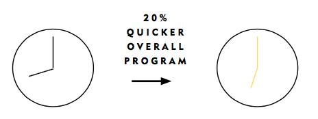
Another key focus during the development of the system was on understanding and capitalising on the benefits of prefabrication. Aside from its environmental credentials, many of the frequently quoted benefits of working with mass timber stem from its prefabrication. Prefabrication can provide high quality, precise products that are quicker, safer and easier to manufacture and assemble than traditional on-site construction methods.
An understanding of Design for Manufacture and Assembly (DFMA) is essential to optimising and realising the potential benefits of timber prefabrication for a specific project.
The Build-in-Wood systems have been developed as a kit of parts for DfMA construction, considering factors such as component sizing and assemby details that help to enable efficient transportation and ease of installation. Successfully designing with DFMA is a holistic process, and as such some key overarching principles are identified here in the hope that this introduction will help to frame the context for specific design decisions. In general, successfully designing with DfMA is a mindset, and as such some key overarching principles are identified here in the hope that this introduction will help to frame the context for specifi design decisions.
Specific DfMA advice is also provided within relevant sections of the booklets where design decisions are most likely to influence a project’s alignment with, and consequently benefits achieved, by DfMA.
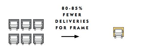
Repetition is a key principle of DfMA construction, one that can offer both cost and time savings during manufacture, by simplifying and shortening time during deliveries and assembly on site. It is also more likely that components will be reused at the end of their life they are repeated within a DFMA kit of parts, due to their increased relevance for other projects, simple identification and well documented performance.
Whilst this logic is inherent in the make-up of the system, limiting the number of component types by for example reducing the number of grid variations or façade bay types in a project can significantly alter the extent to which the ambitions of the system can be achieved, and should therefore be kept in mind during design stages.
The scope of the Build-in-Wood System was purposefully honed by the consortium to focus time and efforts on areas which it felt were most critical to facilitating the increased use of timber in construction. Additional aspirations for maximum design flexibility as well as utilisation of existing available products and systems, where suited to the aspirations of the System, further supported this approach.
In practical terms, this largely related to the integration of proprietary systems and products both to the building interior, in the form of non-structural partitions and doors, and exterior, in the form of windows, doors and curtain walling. These aspects were considered during the research, but the consortium felt just that existing products and solutions already available on the market could be directly integrated into the System in these instance.
Internally, as a post and beam frame, the Build-in-Wood structural system can accomodate virtually any nonloading bearing wall or internal partition system (subject to alingment with project requirements), into which doors, hatches and other features can be integrated as on any other project.
Research was undertaken by the consortium to investigate proprietary solutions that prioritised the use of bio-based and low carbon materials, such as timber stud partitions which it is hoped will be prioritised where permitted by project requirements.
Wetboxes, which are prefabricated volumetric components for areas that require high levels of plumbed services, installations and finishes, such as bathrooms, were also investigated by the consortium.
Integration between these volumetric units and the primary post and beam system was considered, again with a focus on wetbox products that utilised bio-based materials in their own manufacture.
When considering the use of proprietary wetboxes on a project using the Build-in-Wood system, attention should be given to coordinating the scale of the modules with the proposed grid, containment of the modules ‘floor construction’ within the above slab build-up in other areas and, where timber is used within the module, moisture mitigation and detection measures such as tanking and moisture sensors. This consideration is critical due to the increased risk of leaks and other escaped water incidents in such spaces.
Externally, indicative details were also developed for the integration of windows, external doors, curtain walling within and alongside the panels of the Build-in-Wood facade system. These details are not presented, as each project will of course have its own unique requirements; however, they served to support the development of the facade panel stratigraphy to ensure the viability of achieving the necessary performance criteria through such key interfaces.
The incorporation of balconies was also considered and tested for proof of concept that they could be successfully integrated within the system.
For externally integrated proprietary products of all types, special attention should be given as to the durability and combustibility of any bio-based materials included within these products. Users of the system are encouraged to interrogate manufacturers and suppliers in respect to these key criteria to ensure safe and responsible use of timber and other biobased materials.
For further information in respect to integration of proprietary products and details ‘beyond the scope’ of the published System please contact Waugh Thistleton Architects.
NON-STRUCTURAL WALLS
Caption needed 1 XXX-SK-1
WET-BOXES
CURTAIN WALLING