5 minute read
Don’t trust your data sheet sampling rate
Michelle Tate*
Digital storage oscilloscopes (DSOs) are the primary tools used today by digital designers to perform signal integrity measurements such as set-up/hold times, eye margin and rise/fall times. The two key banner specifications that affect the accuracy of an oscilloscope’s signal integrity measurements are bandwidth and sample rate.
Most engineers have a good idea of how much bandwidth they need for their digital measurements. However, required sample rates often cause confusion, and engineers often assume that oscilloscopes with the highest sample rates produce the most accurate digital measurements. But is this true?
Let’s review Nyquist’s Sampling Theorem
Nyquist’s Sampling Theorem states that for a limited bandwidth signal with a maximum frequency (fMAX), the equally spaced sampling frequency (fS) must be greater than twice (2X) the maximum frequency (fMAX) in order to have the signal be uniquely reconstructed without aliasing: f s > 2f max
Nyquist’s Sampling Theorem can be summarised as two simple rules: 1. The highest frequency component sampled must be less than half the sampling frequency. 2. Samples must be equally spaced. (This second rule is often forgotten, but is equally, if not more important to remember. More on this later.)
Some engineers have total trust in Nyquist and claim that just 2X sampling over the oscilloscope’s bandwidth is enough. Other engineers don’t trust digital filtering techniques based on Nyquist criteria and prefer that their oscilloscopes sample at rates that are 10X to 20X over the oscilloscope’s bandwidth specification. While higher sampling rates are advantageous, accurately reconstructing a signal relies on more than a data sheet specification.
Sample rate versus measurement accuracy
Increase sample rate with interleaved real-time sampling Producing higher sample rates in oscilloscopes is not always as easy as simply selecting an off-the-shelf analog-to-digital converter (ADC) that has a higher sample rate. When ADC technology has been stretched to the limit in terms of maximum sample rate, a common technique adopted by all major oscilloscope vendors is to interleave multiple real-time ADCs. Interleaving is the process of multiplexing two or more parallel ADCs to achieve a higher net sample rate than the individual ADCs can achieve alone.
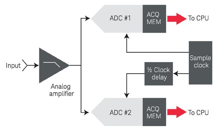
Figure 1 shows a block diagram of a real-time interleaved ADC system consisting of two ADCs with phase-delayed sampling. In this example, ADC #2 always samples ½ of a clock period after ADC #1 samples. After each real-time acquisition cycle is complete, the oscilloscope’s central processing unit (CPU) or waveform processing application-specific integrated circuit (ASIC) retrieves the data stored in each ADC’s acquisition memory and then interleaves the samples to produce a real-time digitised waveform with twice the sample density (ie, 2X sample rate). Higher sample rate doesn’t always make for more accurate measurements Although counterintuitive, increasing the sample rate by interleaving multiple real-time ADCs does not necessarily produce more accurate digital measurements, and can, in some cases, result in poorer signal fidelity due to poorly aligned ADCs.
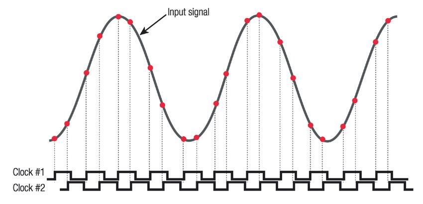
Figure 2 illustrates incorrect timing of interleaved samples if the phase-delayed clock system of two interleaved ADCs is not exactly ½ a sample period delayed relative to each other. When phase-delayed clocking isn’t properly aligned, these digitised points (red dots) are not evenly spaced, which violates Nyquist’s second rule.


©stock.adobe.com/au/agsandrew
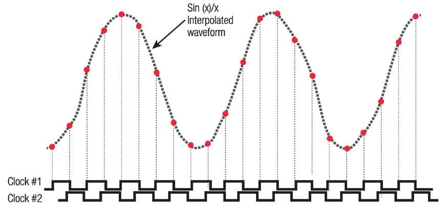
When the oscilloscope’s waveform processing engine retrieves the stored data from each ADC’s acquisition memory, it automatically assumes that samples from each memory device are equally spaced. In an attempt to reconstruct the shape of the original input signal, the oscilloscope’s Sin(x)/x reconstruction filter produces a severely distorted representation of the signal, as shown in Figure 3. So how do we increase the sampling rate and ensure measurement accuracy? Simply speaking, how your oscilloscope interleaves the samples is more important than the number of samples that are interleaved. So, increasing measurement accuracy can be done when using interleaved real-time sampling — if done the correct way.
The key to achieving accurate, distortion-free interleaving — and in turn more accurate measurements — is following two rules: 1. Each ADC’s vertical gain offset and frequency response are closely matched. 2. The timing of phase-delayed clocks aligns with high precision to satisfy Nyquist’s second rule, which dictates equally spaced samples. (Remember I mentioned this second rule would be important!)
Testing for interleave distortion
Unfortunately, unlike sampling rate, oscilloscope data sheets don’t have a specification that directly quantifies the quality of an oscilloscope’s interleaving process. However, you can easily perform a variety of tests not only to identify sampling distortion, but also to measure and quantify the effect of sampling distortion. Below is a list of tests you can perform: 1. Effective number of bits (ENOB) analysis using sine waves 2. Visual sine wave test 3. Spectrum analysis 4. Digital clock measurement stability comparison tests
When you compare the waveform fidelity of scopes of similar bandwidths, Keysight’s real-time scopes produce a true representation of input signals using high-precision ADC technology and precise interleaving.
Keysight has done some of these tests for you. If you want to learn more about how to perform these tests or see the results, check out Keysight Technologies’ Evaluating Oscilloscope Sample Rates versus Sampling Fidelity.1
Summary
Now you know why you can’t completely trust the data sheet when it comes to sampling rates. While a higher sampling rate is typically preferred, when improper interleaving technology (such as uneven intervals) enters the process, it introduces enough inaccuracy to negate this method of achieving a faster sample rate. To truly reap the benefits of higher sampling rates through real-time interleaving, your oscilloscope must follow two rules and not just one.
Want to learn more about oscilloscope sampling? Check out Keysight Technologies’ Evaluating Oscilloscope Sample Rates versus Sampling Fidelity.2
References 1. https://www.keysight.com/us/en/assets/7018-01454/applicationnotes/5989-5732.pdf 2. As above.

Figure 3: Timing diagram showing distorted reconstruction of the waveform using a Sin(x)/x filter due to poor phase-delayed clocking.
*Michelle Tate is currently a Product Marketing Manager for InfiniiVision Oscilloscopes. She worked in the semiconductor industry prior to joining Keysight Technologies. This article was originally published on the Keysight Technologies blog and has been republished with permission.


