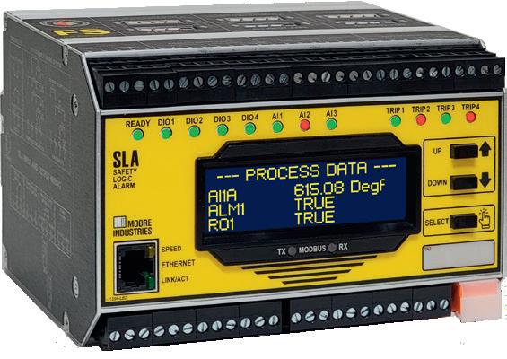


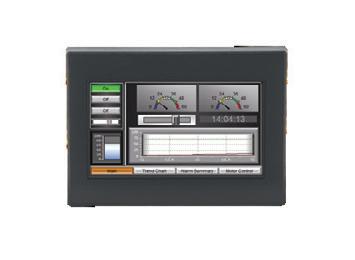


Part of the Moore Industries FS Functional Safety Series, the exida-certified SIL 2/3 capable SLA Multiloop Safety Logic Solver and Alarm is engineered to deliver optimal performance in Safety Instrumented System (SIS) loops. It is designed to bridge the gap between single-loop logic solvers and costly safety PLCs, offering a range of functionalities to provide safety, flexibility and control in critical operations.
With up to 17 I/O channels, simple voting configuration and enhanced maths/logic capabilities typically found in costly and complex safety PLCs, the SLA can handle everything from simple alarming to complex logic schemes including 1oo2, 2oo3 or even 5oo8 voting architectures. Each of SLA’s 16 alarms can be configured for high availability or high integrity, giving users optimal control over shutdown strategies.
The SLA has a powerful, flexible, easy-to-use equation/ expression editor feature that uses spreadsheet-like formulas and prebuilt functions. An equation/expression editor quick reference is available on-screen to help with quick and easy creation of these internal variables. Once built, these variables can be used as alarm input sources, analog output sources or even alarm suppression and reset triggers. Additional advanced functions like timers, running min/max registers and custom curves are also available.
Configured with licence-free FDT/DTM technology such as PACTware, the SLA offers straightforward and quick set-up with easy-to-use pull-down menus, checkboxes and radio buttons.

If the online automation media is to be believed, analog and fieldbus technologies are quickly giving way to Ethernet technologies that have been adapted from the ubiquitous office technology and modified to support time synchronised communication, and (through Ethernet-APL) even made usable in hazardous areas.
Whether that is the case in your plant or not, there is no doubt that the needs of greater production information and asset management are better served by applying a technology that provides greater digital access to industrial assets. I wonder how long it will be before we see fieldbus and 4–20 mA loops become extinct... Only time will tell, but we shouldn’t be afraid of change.
Industrial robotics has also come along in leaps and bounds in recent years and can only improve further through the application of AI. Now that industrial robots are becoming more affordable and more flexible to use (think: cobots), I wonder if Australian industry’s historically slow adoption rate will show any sign of improving. Combining robotics with the AI technology now becoming available should make it easier to achieve even greater efficiencies, as companies move from being robotics entrants through to veterans and even pioneers, as described in this issue’s lead article.
In this issue we also have an interesting technical article on integrating non-binary signals (such as analog values and encoder data) into safety systems, as long as the necessary functional safety protocols are followed, enabling them to play a role in safety decisions.


I hope you enjoy this issue of Process Technology, but as always more detailed daily news and new automation products can be found on processonline.com.au, and by subscribing to our biweekly email newsletter.
Glenn Johnson Editor pt@wfmedia.com.au


Queensland’s Manufacturing Minister Glenn Butcher has announced the Queensland Government has been successful in its bid with the Australian Manufacturing Technology Institute Limited (AMTIL) to bring Australian Manufacturing Week to Brisbane in 2026. This will be the first time the event will be held outside of Sydney or Melbourne.
Butcher said the event will be an opportunity for local manufacturers to showcase their capabilities at the Brisbane Convention & Exhibition Centre.
“If we can make it here in Queensland, we should, and we are,” Butcher said. “Queensland manufacturers regularly exhibit at this event so it’s an incredible opportunity to showcase Queensland’s thriving manufacturing sector.”
“We’re incredibly pleased to be bringing Australian Manufacturing Week to Brisbane in 2026, in collaboration with the Queensland Government,” said AMTIL CEO Lorraine Maxwell. “AMTIL is dedicated to supporting Australia’s manufacturing industry and manufacturers, and events like Australian Manufacturing Week keep our industry connected, competitive and growing.”
The federal government has announced a new grant financed through the Australian Critical Minerals Research and Development Hub to fund a new CSIRO research program that aims to supercharge critical minerals technology and strengthen international collaboration on critical minerals science.
The $2.5 million grant will fund an international R&D collaboration scan, strategic R&D projects across critical minerals technologies, international science delegations, scholarship networks and a critical minerals research summer school for domestic and international researchers.
Federal Minister for Resources and Northern Australia Madeleine King said the grant will help strengthen Australia’s international partnerships as well as build stronger and more resilient supply chains for critical minerals, as the world becomes more reliant on renewable technologies.
“Critical minerals research and development is crucial to developing low-emissions technologies such as electric vehicles, storage batteries and solar panels that will help our international partners lower emissions and achieve their climate commitments,” she said. “The valuable work by the R&D Hub will also support the government’s Future Made in Australia ambition and ensure Australia works with international partners on environmental and social governance standards, commercialisation of research and intellectual property rights on critical minerals.”
Visy has announced the commissioning of what it says is Australia’s most energy-efficient glass furnace at its recycling and remanufacturing facility in Sydney. Officially opened on Thursday, the $150 million investment in Penrith is the country’s first oxygen-only fuelled furnace, using less than half the energy of the one it replaced.
“That’s the equivalent of saving enough energy to heat over 32,000 Sydney homes every year,” said Visy Chairman Anthony Pratt. “Our Penrith site is the only glass bottle and jar manufacturing factory in New South Wales. It produces over 800 million glass containers every year in support of Australia’s world-class food and beverage companies like Vegemite, Cottee’s Jam, Toohey’s New and Bundaberg Ginger Beer.”
The facility will also use advanced recycled cullet pre-heating technology to significantly increase the use of recycled glass in Australia’s glass bottle manufacturing sector.
“This new technology is part of our program to make glass containers with an average 70% recycled content across Australia and New Zealand,” Pratt said.
The factory takes recycled glass from household recycle bins and the Return and Earn container deposit scheme to make the new bottles and jars.

Australian launch services company Gilmour Space Technologies has announced a new suborbital flight test service in Australia aimed at commercial and defence customers that require hypersonic speeds above Mach 5.
“We’ve witnessed a surge in the research and development of hypersonic vehicles, materials and other related technologies in recent years, especially since AUKUS,” said David Doyle, Director of Launch Vehicles and Satellites at Gilmour Space. “However, as many of these ideas progress from concept to prototyping and testing, we’re also seeing a growing bottleneck in high-speed flight test capabilities, beyond what ground-based shock tunnel testing and simulations can offer.”
Doyle noted that while wind tunnel tests (which offer hypersonic flow for 200–300 ms) are excellent for early-stage testing of materials and geometries with scaled-down models, for example, a significant challenge remains in scaling these technologies to full-size applications.
“Our new HyPeRsonic FLight Test (HPRFLT or Hyper Flight) service will help to bridge that gap by providing a real-life

environment for researchers and companies to test, demonstrate and advance their innovations to higher technology readiness levels in Australia,” he said.
The Hyper Flight service, set to launch in 2025 from a few potential sites, leverages Gilmour Space’s orbital launch vehicle technology.
“This is a sovereign, Australian solution for a low-cost, rapid turnkey, hypersonic testbed that will be essential for translating earlystage research into high TRL technologies and platforms that can be used by the Australian Defence Force and our allies,” Doyle concluded.
A critical platform technology to synthesise drug compounds at scale — and onshore production in Australia — has been successfully demonstrated in a collaboration between Melbourne company Boron Molecular, and innovation and technology development specialist DMTC Limited, with support from CSIRO.
‘Flow chemistry’ describes the process of continuous chemical reactions in a pipe or tube, and offers a range of advantages over traditional batch chemistry processing. Advantages include improved energy efficiency and waste reduction, improved safety in the manufacturing environment, a smaller infrastructure footprint and the opportunity to vary manufacturing volumes to meet demand.
In the event of significant supply chain pressures, flow chemistry technology could give Australia a competitive advantage and, critically, ensure the supply of at-risk active pharmaceutical ingredients.
Flow chemistry was initially pioneered in Australia by CSIRO, and the CSIRO team is also supporting the DMTC project.
The Head of the Health Security Systems Australia (HSSA) division at DMTC, Dr Felicia Pradera, said the work to date had successfully demonstrated the scalability of the flow chemistry process.
“In developing sovereign manufacturing capability, speed of response is critical but it’s far from the only measure,” Pradera said. “The team has worked diligently to ensure that technical rigour, quality control and cost-effectiveness have been front-of-mind considerations at every step.
“Beyond the advances in technology, the downstream benefits of DMTC’s collaborative model are also seen in the upskilling of the Australian workforce and the support provided to brilliant young researchers.”
Boron Molecular CEO Dr Oliver Hutt said the project was a great example of empowering Australian industry to rapidly solve big problems.
“In addition to building the pilot plant, our work provides a really comprehensive blueprint for stakeholders to assess the feasibility of this technology,” he said.


Alexander Greenberg, Xin Guo, Shay Shomroni, Siemens Digital Industries Software

Mass production was developed well over 100 years ago. Manual labourers worked on static assembly lines where they built products by hand from various parts and subassemblies. The introduction of automation to manufacturing freed humans from some of the most tedious and repetitive assembly-line tasks, which are ultimately faster and more reliable. These new technologies significantly improved the speed of production. Today, however, the gains made with automation have begun to plateau due to growing product complexity.
A growing trend in industrial and consumer products is an emphasis on customisation, adding to the complexity of products. Because of this, many of today’s products are too complicated to be produced with established automation technologies alone, forcing manufacturers to augment traditional robotics with manual assembly by human labourers. People are valued for their ability to rapidly understand and account for changes in a process. This value is evident for electronic and automotive manufacturers as well as logistics and warehouse operations. Compared to people, who can rapidly make changes and generate their own procedures for a new process, robots are not currently able to efficiently adapt to changes.
A flexible and automated (even autonomous) production system is the Holy Grail for many manufacturers that wish to simultaneously overcome the challenges of growing product complexity and greater customisation. The ability to rapidly switch production from one product to another will be a defining feature of businesses on the path to lot sizes of one and the highly customisable products of tomorrow.
Customisation that requires high-mix production and the complexity it brings are not the only novel requirements in a new era of manufacturing. Manufacturers are looking to strip out waste from their processes to produce high-quality, customised products at a competitive price faster than ever before. This often entails saving materials and energy in production, minimising delays when product changes are required, moving to flexible production with a less experienced workforce and adapting existing production lines to minimise upfront investments and maximise future capabilities. Among these alternatives, flexible automation is considered the key element in addressing the needs of the manufacturing industry of tomorrow.
Based on projections by the International Federation of Robotics (IFR), industrial machine growth is expected to exceed 10% annually over the next three years. This growth is anticipated across many industries, including automotive, electronics and other process-oriented industries like plastics and chemical production. This projected growth is driven by inquiry and investment in new technologies.
Implementing advanced robotics in tomorrow’s manufacturing is a challenge, but also an exciting journey. To understand why, it may be helpful to compare the applications and engineering paradigms of traditional industrial robotics with advanced robotics.
Traditional industrial robots operate in a highly deterministic environment, with fixed robot cells, detailed shop floor layouts and no human co-workers. Any operations completed by the robots are designed to have a negligible or zero fault tolerance. This situation led to predetermined, offline programming based on a detailed simulation environment. Without concurrent operation and planning, iterating the manufacturing process for traditional industrial robotics takes time and resources.
The goal of advanced robotics is to shed this rigidity, enabling operations in an unknown or dynamic environment with frequently changing tasks to produce highly customised products. Advanced robotics is meant to save time and optimise production not only between robots, but with human collaborators. Doing all of this requires runtime decision-making and reactive programming for unforeseen events in the process with concurrent control of the open hardware standards and interfaces. And just like their human counterparts, these advanced robots need to be able to adapt and improve. But instead of using human senses and logic, they will continuously improve from data collected by the Industrial Internet of Things (IIoT) processed with artificial intelligence (AI).
Industry 4.0 and, in turn, advanced robotics are positioned to improve visualisation, enable early validation of designs and facilitate collaboration across a business. To meet these goals, advanced robotics processes focus on implementing a comprehensive digital twin, providing modern and adaptable solutions based on sensing technology and doing all of this while retaining a flexible and open ecosystem.
Every company that is considering or already on the path to implementing advanced robotics will want to proceed in phases to achieve the final goal of advanced robotics. Companies can reside in one of four phases — entrants, veterans, pioneers and visionaries — with most companies today in the first two phases. To reduce overall cost and complexity, these phases are often spread across several years depending on the business and how much investment they can make to progress to the next phase.
Entrants
The first stage on the journey to advanced robotics is the adoption of widely available
fixed automation robotics or similar technology. Businesses within this phase are considered entrants and most of their operations are performed manually. Process plans are designed and assigned by humans and tasks handled by robots are generated based on a specific location and time. Although these machines can be completely reprogrammed for new tasks within the software environment, downloading the new program to the robot involves machine downtime and reduces the overall facility efficiency. Once a machine is running again with a new process, calibration is performed manually based on fixed locations and parts.
Simulation of robotic motion and validation of production processes is also done in this phase, but it is limited to predominately physical aspects of the machines. Mechanical interferences can be checked to ensure full motion, including the validation of the native robot programming, to ensure desired motion. But these capabilities have room for improvement, especially in a world of highly customised products.
With so many labour-intensive tasks required to get a fixed automation robot running a new task, it is easy to see why a facility that handles many different products may want to automate the entire process.
Veterans
In the veteran phase, manufacturers begin adding some higher-level features. This phase is where many using advanced robotics sit, and it requires implementing a digital twin to validate the entire robotic production process, including mechanics and control algorithms. Each of the manual tasks can be simulated within the digital twin to optimise the motion paths of the robots and gain a greater understanding of
the overall system. Digitalising this workflow is key to making improvements later in the transition to advanced robotics.
Process planning is still designed and assigned by humans and robot motion is still manually generated, but the functionality based on the digital twin allows for some higher-level input and display when working with these machines. Robot motion is generated according to system signals and the logic within the PLC on top of what was available in the entrant phase (location and time), a process usually referred to as virtual commissioning.
Now it is possible to see the spacing and interconnectivity of the facility before a machine is physically installed onsite. It is also possible to validate the software running on the PLCs and HMI programs in the virtual environment. Simulating the desired operation at the automation level on down allows for manually optimising the machines so they run as efficiently as possible. It also means even less downtime for the facility as shorter lead times are needed for implementing new or replacement units.
If a large group of robots are completing the same task, the changes can be downloaded to all robots simultaneously instead of manually programming each robot to work properly with its respective task and environment.
This digitalisation also offers the ability to experience the complete facility using virtual reality (VR). In this environment, engineers can evaluate or commission the manufacturing process while immersed in its digital twin. It also allows the comprehensive validation of mechanics and automation, PLC programing and human machine interface programming in VR.
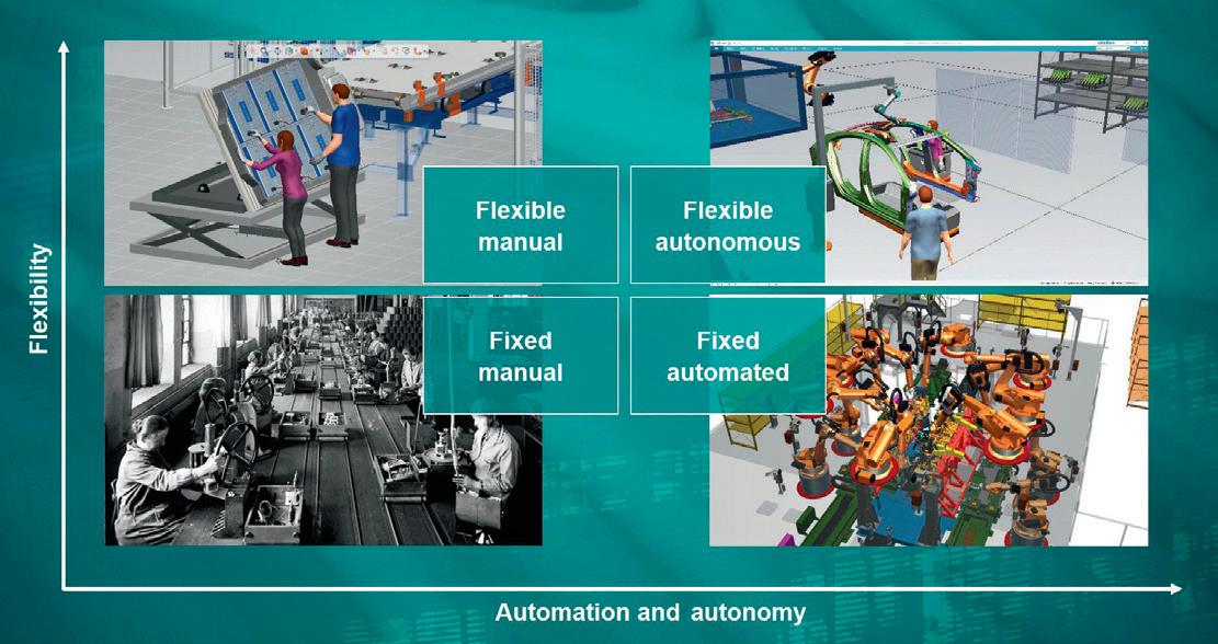
EVERY COMPANY THAT IS CONSIDERING OR ALREADY ON THE PATH TO IMPLEMENTING ADVANCED ROBOTICS WILL WANT TO PROCEED IN PHASES TO ACHIEVE THE FINAL GOAL OF ADVANCED ROBOTICS.
Progressing into phase three, these pioneers of their industries are beginning to automate their production systems. As with the two previous phases, process planning is still done by hand, but that is where the similarities diverge. Robot motion can still be generated based on previously available information, but now there is access to sensor data for feedback optimisation. This could be vision data, force readouts or information from other specialised sensor arrays for the relevant process. The sheer volume of data requires these robots be designed and programmed for adaptive planning based on location, time, signal, PLC logic and sensor data. This results in a higher fidelity simulation and implementation of the production process in non-deterministic working conditions.
Production process simulation can now be performed with varied or flexible parts and a dynamic environment. With easy-touse, task-based programming for feedback control, the manufacturer can create a connected download for the entire shop floor. Semiautomatic programming on the part of the machine frees more resources for other optimisation tasks within the facility.
As an example, a facility may be assembling 5–10 dishwashing machine models. Of these, there could be variable sizes and a few different form factors. It is difficult to assume every product would have the same dimensions and different units may have different hole spacings. Products like these may also be far less rigid than products assembled with traditional robotics that can contribute to suboptimal spacing and a loss of alignment. Instead of programming for every possible array of holes, general definitions are given to the robot. The holes are known to be approximately so far apart, but with the
sensor feedback the robot can readjust the positioning to correctly place a fastener in each hole. This reduces the number of instructions, which in turn reduces the time needed to get these machines operational for new product lines or small changes to the original design.
The companies that implement advanced robotics and reach phase four are set to become the visionaries in their field. Phase four is the complete automation of robotic function; it reaches the upper right corner of the flexibility/automation diagram in Figure 1. Now comprehensive design, simulation and deployment of a flexible production system is possible. Automated process planning and implementation is done by relying on machine learning. Optimisation algorithms integrated with physics simulation are used to train and validate the advanced robotics control scheme. The motion paths are generated automatically based on real-time system data implemented in the previous stages and the system can respond immediately to changes in production.
Machines are updated with automatic program generation while remaining online and as with phase three, each machine implements online closed-loop calibration for both dynamic cells and product variations. By bundling each robot with edge computing devices, the robots can learn
and improve their processes with machine learning. Including 5G communication in the robot edge device systems can also enable a completely mobile, secure and reconfigurable facility. AI drives the manufacturing process and best practices are driven by data to self-optimise and produce the best results.
In the future, automated mobile robots (AMRs) could be used to deliver parts and completed assemblies around the manufacturing floor, replacing traditional conveyor belts. The AMRs could then be included in the complete simulation of the workshop floor to optimise delivery based on robot load or obstructed paths due to humans on the floor.
Mass production has been evolving for over a century and will continue to evolve into the future, but advanced robotics is where today meets tomorrow. By implementing adaptive machines that can not only sense what they are working on but react to that information, factories and other facilities that rely on automation are taking a step towards complete customisation and openness. Advanced robotics takes the complexity that has grown since the inception of mass production and leverages it to develop a highly connected and efficient workflow that can meet the changing needs of a diverse landscape of high-mix production output.
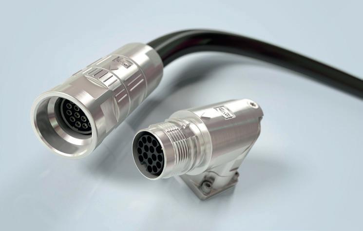
HARTING’s M17 circular connectors are designed to offer a space-saving solution for modern drive applications.
HARTING Pty Ltd
https://bit.ly/4fgYsfX


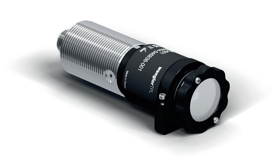
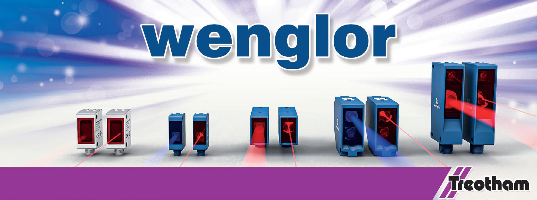
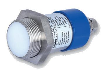
Wenglor’s spotlights with lockable zoom lens offer a variable beam angle to enable improved illumination for industrial image processing.
Treotham Automation Pty Ltd
https://bit.ly/3Spmuvg

The R200 series photoelectric distance sensors integrate pulse ranging technology (PRT) to enable measurement of distances up to 60 m.
Pepperl+Fuchs (Aust) Pty Ltd
https://bit.ly/3SiL5BR

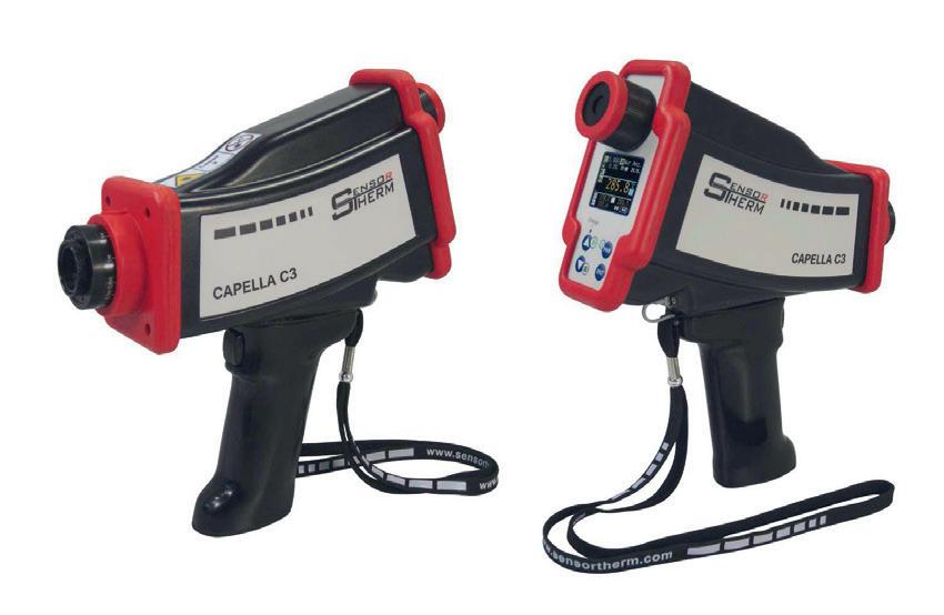
The CAPELLA C3 series pyrometers include singleand 2-colour units with features that include through-the-lens sighting with adjustable focus.
W&B Instruments Pty Ltd
https://bit.ly/4dlkqNb

Siemens has announced an updated generation of controllers. The Simatic S7-1200 G2 controllers are designed to help bridge the worlds of operational technology (OT) and information technology (IT). The controllers offer higher communication performance and more efficient data processing to help increase production output. By connecting the controllers to IT systems, it is also possible to use advanced data analysis, eg, in the cloud.
The controllers are part of Siemens Xcelerator, allowing users to benefit from the standardised engineering approach in the Siemens TIA Portal. The Simatic S7-1200 G2 controller generation enables customers to address major challenges, such as productivity, flexibility and cost optimisation.
Machine builders are facing rising demands for more customised and flexible solutions. This is driving the need for technological advances, such as new motion control functionalities, performance improvements and machine safety solutions.
Simatic S7-1200 G2 controllers are aimed to deliver more versatile and high-precision automation applications, combining integrated motion control functionalities with space-saving and flexible machine safety solutions.
For example, the S7-1200 G2 controllers make it possible for machine builders to control multiple coordinated axes and simple kinematics. Users experience increased performance capabilities due to improved processing power, dedicated communication performance and more memory, as well as near-field communication (NFC) functionality with in-app access to diagnostic, operational and device data. Plain text diagnostic information about the entire PLC station reduces machine downtime and gives users quick access to data.
Siemens Ltd www.siemens.com.au
The 78E Series Ex rotary encoder from Pepperl+Fuchs is designed for applications in hazardous areas. Featuring a flameproof enclosure, this series holds ATEX, IECEx and ANZEx approvals.
Designed to meet the needs of heavyduty mining applications, 78E mining encoders are built to withstand exposure to water and dust and have a flameproof housing. This means that they are designed to provide accurate and reliable measurements in challenging mining environments. The series has a modular design with a removable connection cover that simplifies mounting and maintenance. For fieldbus versions, the bus coding can be freely programmed directly onsite. The 78E encoder has Group I certification for the mining industry and Group II certification for the surface industry.
Pepperl+Fuchs (Aust) Pty Ltd www.pepperl-fuchs.com

The Microsonic LinkControl Adapter LCA-2 is a user-friendly interface for programming Microsonic’s ultrasonic sensors. Key features of the LCA-2 include its three-digit digital display, which simplifies the process of adjusting sensor parameters directly, and the LinkCopy function, allowing settings to be transferred from one sensor to another without a PC, facilitating rapid on-site adjustments. This functionality is especially critical in environments where efficiency and speed are paramount.
The LCA-2 is compatible with Microsonic’s LinkControl software, enhancing its utility when connected to a PC and providing a wide range of control and management options for sensor set-up. The adapter’s robust design is designed for ease of use in demanding industrial settings and for durability and reliability.

Pacific Automation offers dedicated support for the LCA-2, with a specialised product manager available to assist with any technical queries or integration support.
Pacific Automation www.pacificautomation.com.au
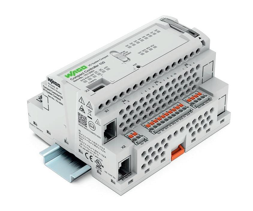
LAPP Australia’s range of automation technologies now includes the WAGO Compact Controller 100 with integrated I/O.
WAGO’s Compact Controller 100 (751-9301) is designed to be adapted rapidly to users’ needs. WAGO is a German company that specialises in spring clamp termination technology for interconnection and automation solutions.
The Compact Controller 100 runs a real-time Linux operating system and supports standard fieldbus protocols for wide interoperability benefits.
The controller includes onboard digital and analog I/Os in a DIN railmountable device housing and supports Modbus (TCP, UDP), EtherCAT Master, EtherNet/IP Adapter (slave), EtherNet/IP Scanner, Modbus RTU RS-485, OPC UA Server/Client and MQTT fieldbus protocol support.
Configuration utilises the manufacturer-independent CODESYS V3 engineering environment.
LAPP Australia Pty Ltd lappaustralia.com.au

Harry Mulder, Beckhoff Automation*

Non-binary signals such as analog inputs and encoder readings are very common and should be incorporated into safety programs.
Electrical safety systems experienced a breakthrough in the mid-1990s with the advent of the IEC 61508 standard. Titled Functional Safety of Electrical/ Electronic/Programmable Electronic Safety-rated Systems, it effectively allowed microprocessor-based controllers to be used within safety circuits, thereby ushering in the era of functional safety.
Prior to the release of IEC 61508, users were forced to resort to safety circuits that were all hardwired. These were far more cumbersome to build and difficult to faultfind, but the heavy regulation demanded by the laws around workplace safety meant there was no choice.
Programmable controllers on the other hand give users far more flexibility when designing safety-rated systems. They are faster to create, simpler to change and easier to duplicate. The move towards programmable safety is much like the transition away from hardwired relay circuits to PLCs that occurred several decades earlier.
Safety Integrity Level (SIL) as defined by IEC 61508 is a measure of a component’s reliability — the more reliable it is, the less likely it is to fail dangerously, and the higher its SIL rating will be. Modern safety controllers can achieve ratings of up to SIL 3, and many also comply with Category 4 (EN 954-1) and PLe (Performance Level e, according to IEC 13849-1). Such high levels of protection are attained by implementing a series of measures, such as extensive self-diagnostics and internal monitoring of voltages, on-times, temperatures and more.
Additionally, both CPUs and compilers utilise the concept of ‘diverse redundancy’. This is where a program is compiled using two dissimilar compilers, often produced by different vendors. Each compiled program is then run independently but in parallel, using two dissimilar CPUs, again usually manufactured by different vendors. The result of each program is compared at the end of every execution cycle, with the system resorting to its safe condition in the event of any discrepancies.
Many safety controllers still operate exclusively with digital signals, which adhere strictly to only on and off conditions. Binary devices, such as switches and sensors, are connected to input terminals and are evaluated for their high or low logic state. The program then determines an output state of either on (the active state where the machine can safely run) or off (the safe state, where outputs are watt-less, causing at least part of the machine to stop).
However, most industrial applications also use continuously varying signals, such as analog values for level or pressure, load cell analysis, temperature measurements and the like. Encoders are also commonly used for rotating devices, and these produce their own unique signal types, such as EnDat absolute encoders.
None of these signal types are binary, meaning most safety controllers have no means of evaluating them. Yet they are an integral part of the overall system and should therefore play a role in the decisionmaking process within the safety controller.
Ideally, it should be possible to incorporate these signal types into a safety controller in a cost-effective way.
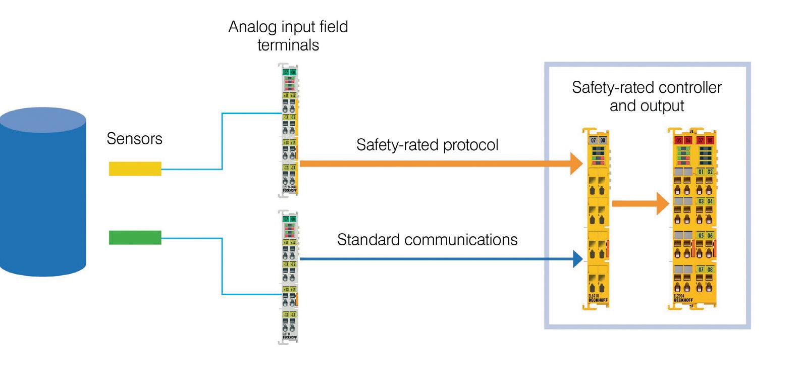
While standard PLC signals are not safety rated, they can nonetheless be used in safety circuits for non-critical purposes, such as resets. It’s also possible to integrate standard non-binary inputs, such as analog values, as shown in Figure 1. Certain usage protocols will, however, need to be strictly followed. It is also important to note that once standard signals are introduced into a safety system, the overall safety will be derated to a maximum of SIL 2, Category 3 and PLd.
It is vital that users understand the safety ratings of their machinery, and how it compares with the PLr (Performance Level requirement), as stipulated by the risk assessment made for that machinery (as per ISO 12100:2010). Furthermore — as with the implementation of any safety system — users must closely follow all documentation produced by the product vendors. No guarantees of operation or protection levels can be made if vendor documentation is not properly observed.
The sensors in the field do not need any official certification be used in safety systems, although they must follow the rule of divergent redundant channels. This means that for every non-binary input, at least two sensors must be installed for redundancy. These sensors must also be of a different type and be wired in isolation to each other. They must connect to different terminals, at least one of which must use a safety-rated protocol to communicate to the safety controller.
IT IS ... IMPORTANT TO NOTE THAT ONCE STANDARD SIGNALS ARE INTRODUCED INTO A SAFETY SYSTEM, THE OVERALL SAFETY WILL BE DERATED TO A MAXIMUM OF SIL 2, CATEGORY 3 AND PLD.
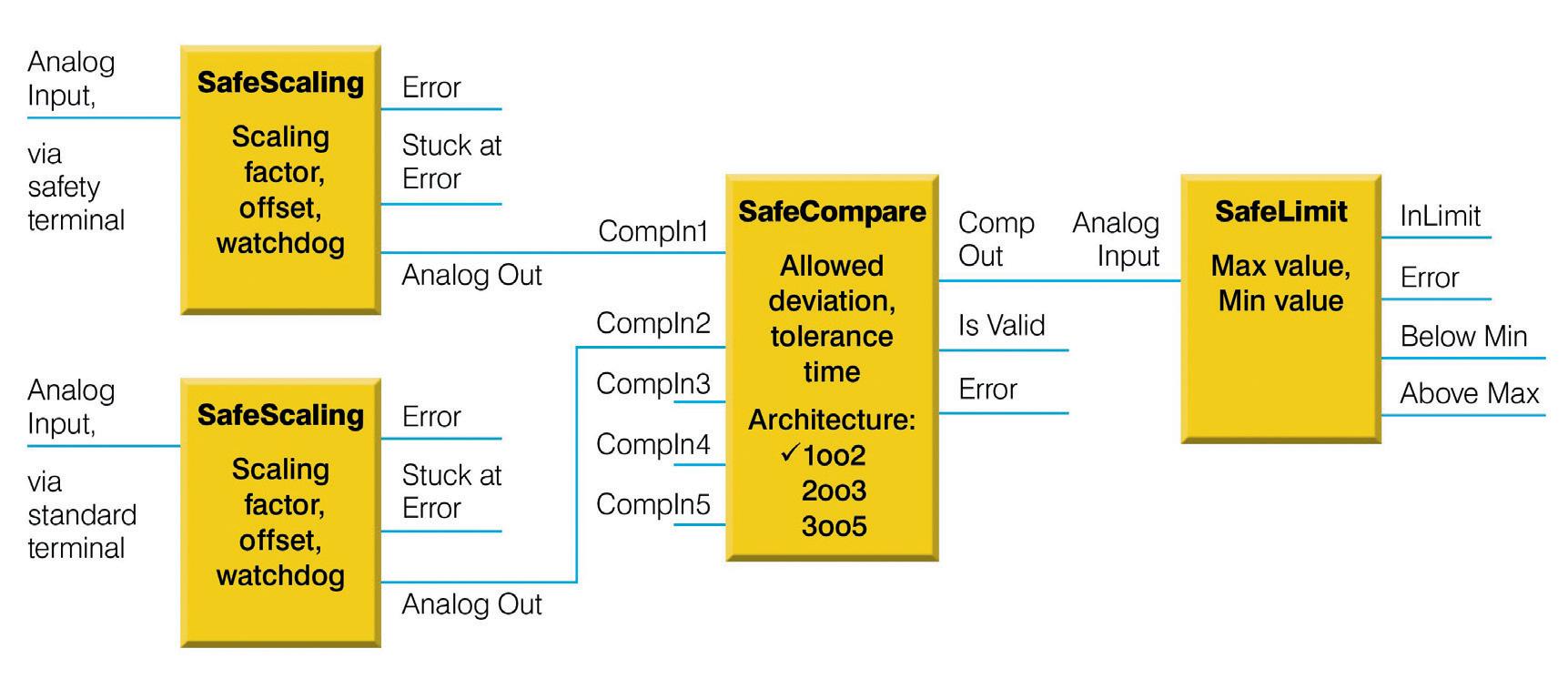
A watchdog ensures values continually deviate slightly, so that inputs that are ‘stuck’ at values can be detected, as this could suggest faulty sensors.
The requirement for divergent redundant sensor handling is to overcome commoncause failures (CCFs), where a single event or shared factor causes multiple sensor failures. One example is where an RTD sensor fails when the temperature it’s measuring exceeds a certain level. If two of the same sensor types were used, then both would fail. But this situation can be avoided by using different temperature sensors, for example a thermocouple as well as an RTD. CCF is also the rationale for utilising separate compilers, each generating their own code, to execute on divergent CPUs.
Figure 2 shows how a safety controller can evaluate redundant analog signals via a three-stage process: scaling, validation and limiting. Each input signal is scaled individually to ensure integer values are used (to avoid ambiguity caused by differences in precision) and are bounded correctly (to avoid overflows that subsequent multiplication operations could cause).
The output format of the scaling functions allows the input signals to be compared directly to each other in the second stage. If the deviation between the signals is excessive, the inputs are deemed invalid — meaning the safety output will fall back to its safe state. Both the amount of deviation and the tolerance time are set within the function block, the latter allowing for some settling time of the signals.
A comparison function block can accept up to five divergent inputs, all measuring the same parameter in the field. Users can select majority inputs between either 1oo2 (one of two), 2oo3 (two of three) or 3oo5 (three of five) for its validated output signal.
The final stage is the limit test, to confirm if the (validated) input level falls within a specified range. Both minimum and maximum values can be set, either as parameters within the function block or as inputs. While inputs can be varied during program execution, care should be taken as to the source of the input signal. The limit function block provides three outputs: below, in-range and above the specified limits.
Although this example only shows an analog value, other signal types such as temperature and encoder inputs are handled in a similar way. Many safety-rated function blocks exist, including arithmetic operations (for addition, division and the like) and motion operations (such as speed limiting
and cam monitoring). Highly complex safety functionality can be created when using these function blocks in combination. Examples include SafeCounters, SafeSpeed, SafeLoadSharing and SafeEnvelopes.
It is permissible for one of the input sources to be derived internally from within software. Motion applications are an example of this, where the servo’s encoder reading (held within the axis) is used as the standard input. A secondary encoder still needs to be mounted in the field as the diverse channel. Importantly though, this means standard motors can still be used within safety circuits.
Non-binary signals, such as analog and temperature inputs, and encoder readings, are very common in control applications. They should therefore be incorporated into safety programs, which ensure electrical systems remain safe to use. Where these signal types are handled in a safety controller, users are given a far richer set of tools to work with. While the maximum achievable safety ratings for these systems are reduced, they are still workable. These systems remain a cost-effective safety solution for many users.
*Harry Mulder is the Principal Automation Engineer at Beckhoff Automation. He has been involved in industrial automation for over 30 years and is fascinated by how new innovations keep affecting the direction of the industry. He really enjoys the practical element of his job, where he has a chance to get his hands dirty!


Macadamias are famously the world’s toughest nut to crack. Requiring an extraordinary 300 psi of pressure, it is usual to buy these tough nuts without their shells. Happy Nut by Freedom Fresh Australia is among the exceptions. Freedom Fresh has long supplied its Happy Nut brand with a specially designed metal key: the macadamia nuts are roasted with a slit sawed into the shell, meaning customers can crack them open easily using the tool provided.
The challenge the business faced was automating the placement of the keys into bags during the filling process. The manual method was cumbersome and inefficient. It involved a worker standing on a ladder for prolonged periods of time and physically placing a key into each bag. The benefits of shifting from manual to automated processing was obvious: the manual task was repetitive and posed obvious safety risks — not to mention the monotonous nature of placing up to 20,000 keys into bags each day.
The goal of the automation project included automatic pick and place of up to 60 keys per minute, seamless integration with the existing production line and a minimal factory floor footprint.
To meet the requirements, the Freedom Fresh team enlisted automation service provider M.A.P Services, the authorised Australian distributor for TM Robotics and Shibaura Machine industrial robots. The M.A.P Services team selected the THE400 robot from Shibaura Machine as the foundation for the system.
“The THE400 met all of the requirements for the Freedom Fresh project,” said Nigel Smith, Managing Director and CEO of TM Robotics. “With a 400 mm arm length, the robot is relatively compact and requires minimal factory floor space. It also offers a cycle time of 0.39 seconds with a 2 kg load and accurate movement trajectory.”
The robot was equipped with the TS5000, a high-speed robotic controller, also from Shibaura Machine. M.A.P Services also integrated an ifm O2D camera for vision processing and an encoder for conveyor tracking, with vacuum gear from SMC handling the pick-and-place mechanism.
The automated process begins with the O2D camera monitoring a continuous stream of keys on a conveyor. Upon triggering, the camera captures an image and uses its in-built contour detection to locate each key. The camera then sends the position of each key to the robot controller via an Ethernet network.
“Integrating the vision system and encoder with the new-generation TS5000 controller presented some initial teething issues,” Smith said. “However, the user-friendly interface of the controller and the Shibaura Machine robot teach pendant made the integration process significantly easier. Our robot experts worked collaboratively with M.A.P Services to ensure seamless integration.”
The robot syncs with the encoder for accurate conveyor tracking, picks up the key with a suction cup and carries it to the drop point. There, it waits for a signal from the nut-filling machine before releasing the key. This cycle repeats every second, ensuring a high-speed operation.
Freedom Fresh Australia expressed immense satisfaction with the solution, the project having exceeded the company’s expectations. The automated system exceeded the cycle time requirement, achieving higher efficiency and reliability.
“Our experience with the new system has been an 11 out of 10,” said Trevor Steinhardt of Freedom Fresh Australia. “The job of placing keys into bags was a difficult one, and there was no mechanical solution we could find. Now, the system just runs. It is coping very nicely and the strike rate is far better than a human operator.”
The collaboration between TM Robotics and M.A.P Services was also noted as instrumental to the project’s success.
“It was the customer-centric approach that delivered outstanding results,” Spiteri added. “We ensured that we understand and addressed the specific needs of Freedom Fresh Australia. This effort led to a tailored solution that has exceeded the customer’s expectations.”
TM Robotics
www.tmrobotics.com


The Argus/Xtralis series of aspirating smoke detectors bring the latest and most advanced detection technology to provide very early warning and the best nuisance alarm rejection to a wide range of applications. Building on the advanced technical base of Xtralis, Argus has modified and extended the technology to support a broad range of cotton-processing applications. Based on the Flare Detection Technology and years of application experience, these detectors acheive consistent performance over their life time via absolute calibration.
The Argus linear heat detection system is easy to integrate into fire management systems. It can be configured with one, two, or four channel search providing up to a 10 km range (6 km for a fourchannel configuration). Each channel has 1,000 programmable zones, each with the ability to be configured with individual alarm and pre-alarm criteria. High sensitivity and fast response time ensure quick fire detection and precise localization of the source. The controller is a “solid state” device that has no moving parts, is immune to electromagnetic disturbances, and it has a Mean Time Between Failure of more than 45 years, ensuring reliable fire detection in even the harshest environments.
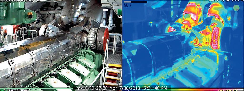
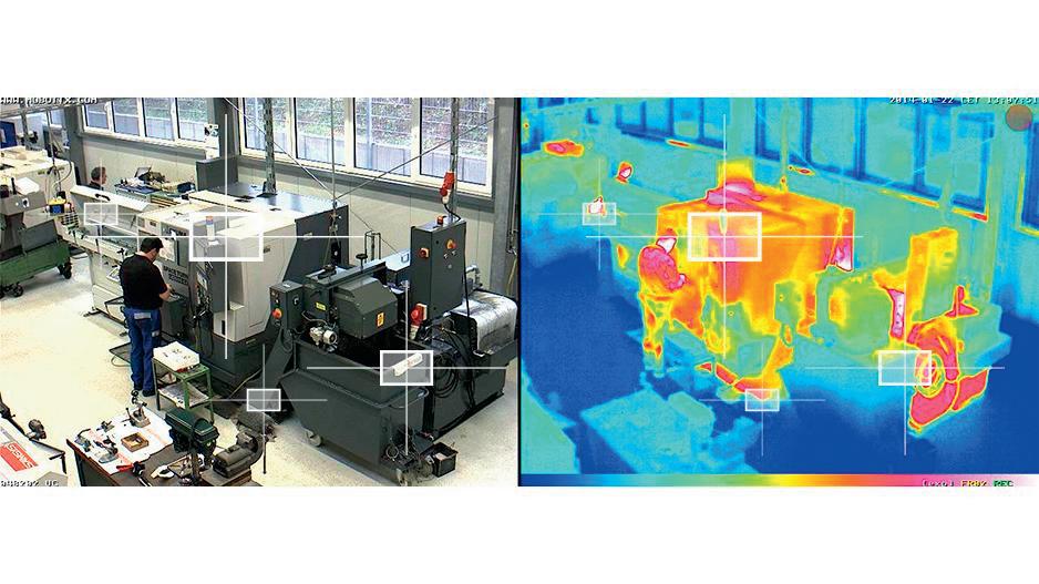
Argus the most advanced and intelligent thermal imaging technology available to the textile industry.
Argus Thermal Imagers feature a calibrated thermal sensor capable of measuring thermal radiation across the entire image area and will trigger an event if thresholds are exceeded. The camera has the ability to detect early signs of where a fire may occur long before the flames are visible. It has a wide range of temperature analysis functions as well as the ability to define complex event logics.
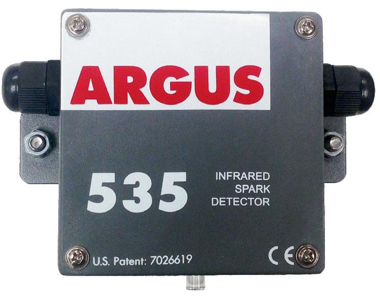
• Integrated EOL (End of Line) Module.
• External LED indicating proper operation (green) or alarm (red).
• Improved duct mounting system for ease of installation and maintenance.
• Patented design & circuitry eliminates reaction to static electricity.
• Operates in temperatures from -40°C to +85°C.
• Detects sparks as small as 2 millimetres.
• Detects sparks at speeds up to 60 metres per second.

SMC Corporation’s latest electric actuator series, the EQ series of slidetype and rod-type actuators, feature a fully integrated controller, designed to provide a simpler-to-set-up, easier-to-use, space-saving solution that simultaneously helps save energy and reduce CO2 emissions.
The EQFS (slide type) and EQY (rod type) electric actuators are designed to overcome automation project challenges such as labour-intensive wiring, downsizing control cabinet space, reducing power demand and eliminating time-consuming programming and commissioning.
The EQ series is suitable for applications such as transfer, assembly, lifting, dispensing, pressing and clamping, or wherever a higher degree of precision or control is required or where compressed air is not available.
The electric actuator and controller are integrated, saving on wiring time and space. The series includes an optimised motor specification, updated control method and improved rotational efficiency, resulting in reduced heat generation from the motor and lower power consumption. “Depending on the operating conditions, it is also possible to reduce emissions by up to 60% compared with existing solutions.”
To simplify retrofit applications, the EQ series has the same mounting dimensions as the SMC LEFS or LEY standard electric actuator series, making for easy replacement.
All EQ series e-cylinders already come standard with an absolute encoder system, but if further external sensing is required, they are compatible with standard SMC D-M9 series auto switches.
SMC Australia | New Zealand www.smcanz.com
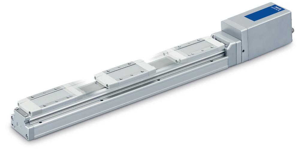
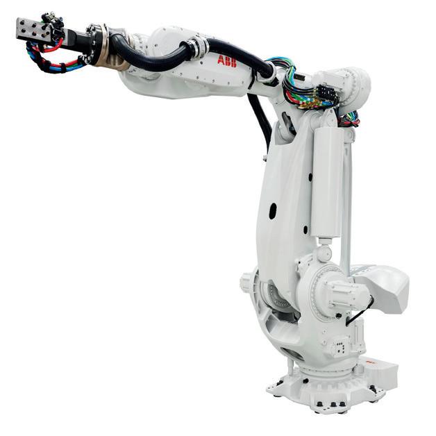
ABB Robotics has expanded its modular large robot range with the introduction of the IRB 7710 and IRB 7720. These robots, combined with recently launched IRB 5710-IRB 5720 and IRB 6710-IRB 6740, offer a combined total of 46 different variants capable of handling payloads between 70 and 620 kg.
The IRB 7710 and IRB 7720 robots offer 16 new variants and are suited to support applications across various industries, for high payload assembly, such as gigacasting, high-speed press tending and palletising, and high-accuracy contact applications such as machining and friction stir welding.
Powered by ABB’s OmniCore, the robots are said to achieve motion control with path accuracy down to 0.6 mm, even with multiple robots running at high speeds of up to 1600 mm/s and moving payloads of up to 620 kg. Users can also benefit from an up to 25% reduction in cycle times.
The IRB 7710’s energy-efficient design in combination with OmniCore’s regeneration technology is also said to achieve up to a 30% energy reduction, while a built-in power pack can relay energy back to the grid.
ABB Australia Pty Ltd www.abbaustralia.com.au

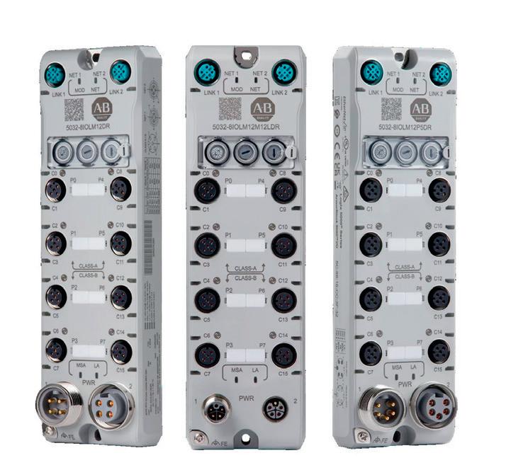
Rockwell Automation has released enhanced firmware and an Add-on Profile (AOP) update for the Allen-Bradley ArmorBlock 5000 IO-Link master blocks. The added features, coupled with the On-Machine capability, provide a boost in functionality and performance for applications within demanding industrial environments.
Added capabilities include a generic IO-Link profile that allows compatibility with a wider range of IO-Link devices, enabling expanded machine capabilities for existing automation systems. Process Data-only mode further simplifies IO-Link integration by transmitting data specified by the IO-Link device.
Automatic download of IODD files via the IO-Link device registration tool helps to simplify the workflow, speeding up configuration and optimising overall efficiency, while EDS file import/export functionality enables more efficient project deployment where users can leverage the same EDS file across different machines.
Change type functionality now allows the replacement of an IO-Link master block with a different power variant without device and software reconfiguration.
Rockwell Automation Australia www.rockwellautomation.com/en-au.html
The ICP DAS ALX-9191 programmable automation controller is powered by an Intel Atom E3950 processor, which operates at speeds ranging from 1.6 to 2 GHz, and has 8 GB DDR4 SDRAM and a 64 GB SSD. The PAC runs Linux Ubuntu 20.04 with Kernel 5.4, and visual outputs are provided via VGA and HDMI ports.
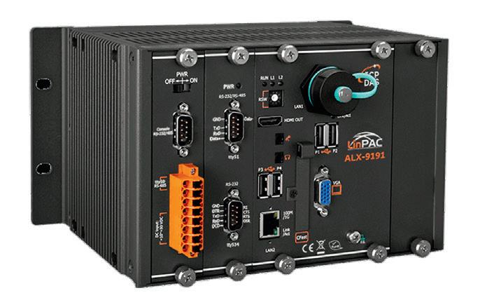
The product offers 10/100/1000 Mbps Ethernet ports and four serial ports (RS-232/485), as well as a built-in real-time clock, while redundant power inputs make uninterrupted operation a possibility.
It also supports external storage expansions like CFast cards or USB mass storage. With the provision of the LinPAC SDK, developers can create tailored applications using GNU C Language.
ICP Electronics Australia Pty Ltd www.icp-australia.com.au


Lisa Chang Product Manager, Leann Wang Product Manager, Moxa
Ethernet, which marked its 50th anniversary in 2023, remains an everevolving transformative networking innovation that sets the foundation for future connectivity. To ensure Ethernet technology remains relevant for industrial applications, continuous advancements are necessary. These advancements may include improving data transmission speeds, providing real-time and reliable communication, and supporting a greater variety of connections. Hence, it is vital to explore new possibilities and push the boundaries of this established technology.
With Industry 4.0, the focus has shifted from simply establishing connections between devices to effectively accessing and using data. To achieve real-time data management and transmission, the key is the construction of a flat and unified network architecture that enables seamless communication between IT and OT systems throughout the entire network.
Because of its reliability, security and simplicity, standard Ethernet has been a proven communication technology in IT applications for decades. Now it will also play a crucial role in vertical integration and cross-system collaboration in the OT domain. Here, standard Ethernet enables effective communication among different devices and systems, achieving reliable and secure data transfers.
Time-sensitive networking (TSN) and single-pair Ethernet (SPE) have emerged as the two important Ethernet technologies that enable the development of a unified industrial network and push Ethernet’s capabilities to new heights. Leveraging standard Ethernet, TSN facilitates real-time and deterministic communication and establishes a unified industrial network

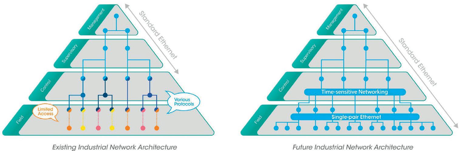

backbone for a variety of systems. With the use of just two wires, SPE enables the transmission of data and power over long distances, extending Ethernet to the industrial field, connecting the last frontier for a truly unified industrial network.
The future of industrial networks is largely centred on TSN, according to industry forums. Using TSN, deterministic services can send time-sensitive data over standard Ethernet networks. TSN incorporates network traffic management to maintain strict timeframes for end-toend transmission latencies. All TSN devices must synchronise their clocks with each other and use a common time reference. Additional traffic control can be included to establish a fully deterministic network. Thus, leveraging TSN’s deterministic capabilities enables real-time communication for industrial control applications using standard Ethernet. Furthermore, TSN can transmit a variety of communication protocols and coordinate different systems without interference, facilitating a unified and open network architecture.
TSN’s success in various sectors show its effectiveness as a unifying platform for integrating different systems. Implementing TSN in manufacturing, for example, has reduced production cycle times and total cost of ownership. In a home appliance manufacturing scenario, for instance, TSN realised a real-time, deterministic network infrastructure and enabled precise control and synchronisation of production line devices and processes.
As TSN expands its capabilities, we recognise common network requirements across different applications. To meet evolving needs, TSN must continue to adapt.
As unified industrial networks expand and integrate diverse applications and devices, they demand new requirements from TSN technology:
• Higher port counts: With the need for more and more device connections, TSN network devices must have larger port counts to accommodate the growing demand for future networking.
• More bandwidth: The rise in ports, devices and TSN-enabled applications leads to increased data traffic. Bandwidths of Gigabit, 10G, or higher are necessary for processing and transmitting such large volumes of data.
• Different form factors: With the increasing adoption of TSN in various applications, the demand for TSN network devices with different form factors is also rising.
• Easier management: As the number of devices and applications in a TSN network grows, the need for management and configuration tools becomes more apparent. Tools such as central network controllers (CNCs) are essential for simplifying network management and configuration.
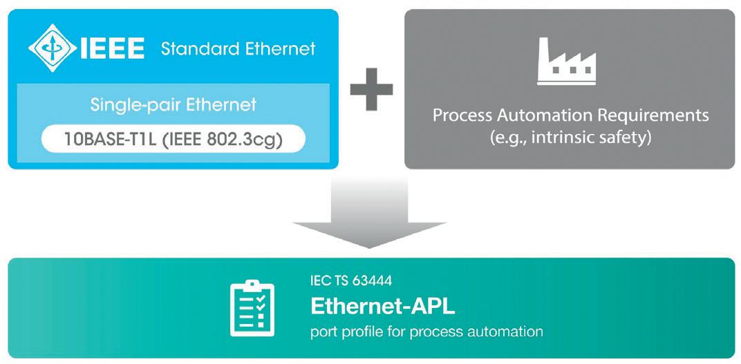
SPE refers to four IEEE Ethernet standards: IEEE 802.3ch, IEEE 802.3bp, IEEE 802.3bw and IEEE 802.3cg. Each specifies a transmission distance and speed, varying from 10 Mbps to Gigabit and from 50 m to 1 km — all based on two wires. With a single pair of copper wires for both data and power transmission, SPE offers several advantages over traditional Ethernet wiring, such as being lighter, more space-saving, less expensive, easier to install and wire, and faster to implement.
Before, standard Ethernet provided a copper connection with four or eight wires and a defined transmission distance restriction up to 100 m. This was not suitable for adoption in industrial field applications. Nevertheless, SPE has changed things for the better, expanding Ethernet networking possibilities in various field applications. As SPE connects devices and equipment at the field level with the upper network, it enables the entire system to achieve a unified network architecture. This integration allows seamless data transmission to improve production efficiency and reduce production costs by using technologies like predictive maintenance and other data-driven applications.
However, various applications have different requirements. Let’s examine how SPE is revolutionising the process automation industry.
The power of SPE in process automation: Ethernet-APL
In process automation, especially within the chemical and oil & gas sectors, common requirements include transmitting data and power simultaneously on the same cable over distances exceeding 100 m and operating in hazardous environments with intrinsic safety requirements.
IEC TS 63444:2023 outlines Ethernet Advanced Physical Layer (also known as Ethernet-APL), which is designed for hazardous areas in process automation plants. It incorporates SPE technology — IEEE 802.3cg: 10BASE-T1L — and explosion protection through intrinsic safety (IS).
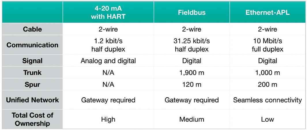
In the past, process automation relied on multiple technologies like 4–20 mA analog loops and various fieldbuses. However, as market demands for more data access and optimisation increase, the limitations of legacy technologies are becoming clear. These legacy technologies pose obstacles between upper network layers and the field level, as well as security risks and limitations because of slow transmission speeds and complex system integration. Furthermore, managing multiple communication protocols in the field is both complex and costly, as it involves implementing intricate protocol conversions, maintaining different systems and allocating multiple groups of professionals.
Despite the significance of standard Ethernet solutions in enabling an open and unified architecture for industrial automation, field-level applications have not always reaped the benefits. Now EthernetAPL offers a fully compatible two-wire, intrinsically safe, long-distance solution that
also offers power supply on a two-wire capacity — empowering process automation applications to establish a unified network from the management system to the field, using standard Ethernet.
With Ethernet-APL, users can expect much higher speed and improved data access, surpassing existing 4–20 mA and fieldbus solutions. For example, EthernetAPL provides speeds of 10 Mbps, 300 times faster than fieldbus. Beyond speed, Ethernet-APL offers the advantage of protocol independence, allowing for the use of multiple protocols with no need for a gateway. With Ethernet-APL, complex device set-up and system calculation are no longer necessary compared to fieldbus or analog systems, resulting in significant cost and effort savings across engineering, installation, commissioning and operations. More importantly, with improved data availability and a unified architecture, efficient monitoring and optimisation of field processes become workable.
In the age of Industry 4.0, network transformation plays a crucial role in driving digitalisation and intelligence in the industrial sector. The adoption of standard Ethernet technologies to achieve a unified network can elevate production efficiency and propel the evolution of intelligent manufacturing.
The shift in networking has great importance for industry, empowering businesses to navigate dynamic market conditions with agility, optimising their production processes for increased effectiveness and establishing a sound basis for ongoing innovation in future industrial practices. At its core, TSN serves as the cornerstone of this unified infrastructure and the emergence of SPE brings us closer to a unified network by extending Ethernet to industrial fields.
Colterlec Pty Ltd www.colterlec.com.au

Australia, much like the United States and Canada, is facing significant challenges in protecting its critical infrastructure from cyber threats. During a recent trip across the Asia–Pacific region, I observed a keen awareness among organisations about the necessity of bolstering their cybersecurity measures. However, gaps in strategy, resources and testing continue to hinder comprehensive security implementations.
The industrial sector in Australia is navigating a similar trajectory to that of North America. Many organisations have embarked on their cybersecurity journey. Yet, the maturity levels vary, and numerous gaps still remain, particularly in operational technology (OT) environments. Unlike non-industrial business environments, OT sectors grapple with unique challenges that impede the adoption of comprehensive security measures.
While challenges in OT cybersecurity can be varied depending on the organisation and the industry sector, there are recurring trends.
There are still human and cultural barriers in the relationship between process engineers and cybersecurity professionals, historically fraught with misunderstandings stemming from divergent priorities and terminologies. For instance, imposing enterprise cybersecurity controls on process environments is often unfeasible due to the sensitivity and age of industrial equipment.
Legacy systems and vendor-controlled equipment are also prevalent in industrial environments. These systems are typically designed to operate continuously for decades, often with minimal maintenance windows, presenting technical hurdles to be overcome to implement modern cybersecurity tools.
In addition, critical processes often cannot afford downtime, making it difficult to implement and test security measures. This necessity for uninterrupted operations leads to a conservative approach, prioritising stability over security.
The Dragos Australian ‘2023 OT Cybersecurity Year in Review’ provided a view of the significant cybersecurity trends impacting industrial infrastructure organisations, which recorded 905 global ransomware incidents last year. Of these, 13 incidents involved Australian organisations, such as DP World Australia, which brought into focus the possibility of cascading effects and impacts of ransomware on industrial operations, supply chains and consumers.
Australia’s threat landscape is not unique and does mirror global trends, with three primary categories of cyber threats affecting industrial organisations.
Firstly, commodity malware and ransomware pose a significant threat to industrial environments, and while the ransomware itself might not
directly damage industrial processes, it can disrupt operational visibility, causing substantial operational and safety concerns.
Secondly, insider threats — often unintentional — arise from poor security practices and inadequate understanding of cybersecurity protocols. This can be instances of unauthorised devices connecting to networks, improper use of USB drives and inadvertent internet connections, which can expose critical systems to external threats.
Lastly, advanced persistent threats (APTs) from state-sponsored adversaries that engage in industrial espionage and reconnaissance are sophisticated threats involving detailed knowledge of specific industrial systems and require extensive reconnaissance to exploit vulnerabilities effectively.
Addressing these challenges necessitates a multifaceted approach. Improving the collaboration between cybersecurity professionals and process engineers is crucial. Joint training programs and cross-functional teams can bridge the gap, fostering a culture of mutual understanding and cooperation.
Given the technical constraints, a phased approach to cybersecurity implementation is also advisable. Organisations should first prioritise critical vulnerabilities and gradually integrate advanced security tools, ensuring minimal disruption to operations.
Organisations must also move beyond theoretical planning with regular testing and drills essential to help validate the effectiveness of security measures. Comprehensive threat modelling should also be undertaken to understand the full spectrum of potential threats, identify and prioritise risks, and tailor cybersecurity strategies accordingly.
The path to robust cybersecurity in Australia’s industrial sector is challenging, but not insurmountable. By addressing human, technical and procedural barriers, organisations can significantly enhance their defences against what are rapidly evolving cyber threats.
As we move forward, it is imperative for organisations to recognise that cybersecurity is not a one-time effort, but an ongoing process that requires vigilance, adaptability and continuous improvement.
While the road ahead may be complex, with concerted efforts and appropriate strategic planning, Australia’s industrial sector can rise to meet the cybersecurity challenges of the modern era.
*Lesley Carhart is Director of Incident Response for North America at Dragos, Inc., managing a team of professionals in industrial cybersecurity. A retired US Air Force Reservist, Lesley has received numerous accolades, including DEF CON Hacker of the Year. Lesley also teaches, lectures and blogs about cybersecurity.

Advantech has launched the ARK-1125 series, a line of palm-sized intelligent edge computers. Designed to meet the demands of various IoT applications, these compact devices feature Intel Atom x6000E processors for robust performance and energy efficiency.
The ARK-1125 series offers a fanless design with a wide operating temperature range, providing durability and reliability even in harsh environments.
The ARK-1125 devices come equipped with multiple I/O interfaces, including USB 3.2, COM ports, HDMI and LAN ports. They also support wireless communication through optional Wi-Fi and 4G/LTE modules, providing flexibility and scalability for different deployment scenarios.
These edge computers are designed for real-time data processing and analytics at the network edge, enabling faster decision-making and reducing latency. This makes them suitable for applications in automation and smart manufacturing, where timely data insights are crucial.
The ARK-1125 series supports multiple operating systems, including Windows 10 IoT Enterprise and Linux, offering developers a flexible platform for creating their solutions. The inclusion of Intel’s Programmable Services Engine (PSE) provides enhanced security features for data integrity and protection against cyber threats.
Advantech Australia Pty Ltd www.advantech.net.au
Pilz PSENini inductive safety switches detect the approach of metallic objects without contact and supply the necessary safe signals for position and end limits. PSENini can also be used to generate pulses for counting tasks or for detecting rotational movements without the need for uniquely coded actuators. It is space-saving, reacts to metals and is easily integrated into the machine.
Multiple versions provide flexibility for application integration: the cube-shaped proximity switch with a plastic housing detects objects within a 15 mm operating distance, and with protection class IP68/IP69, the three cylindrical models with stainless steel housings allow for operating distances of 2–10 mm and are also appropriate for more hygiene-critical applications. The operating temperature range of the sensors is -25 to +70°C.
Inductive safety sensors are used in a broad range of industries, such as in packaging plants, food and beverage, and toolmaking sectors. The standardised OSSD safety outputs on the inductive safety switches make integration simple and enable a direct connection to the appropriate safety controller, such as PNOZmulti, myPNOZ or PSS4000.
The sensors have no blind range, so no minimum distance is required between sensor and object, and they can be used in safety applications up to PL d, Cat. 2 (EN ISO 13849-1) or SIL 2 (IEC 62061). Redundant use enables up to PL e, Cat. 3/SIL 3.
Pilz Australia Industrial Automation LP www.pilz.com.au
Festo has announced a high-precision VTEP proportional valve terminal that it says opens up new application areas.
Festo’s Controlled Pneumatics is a compressed air technology that makes pressure control for the VTEP highly sensitive, down to less than 1 mbar, making it suitable for applications such as wafer polishing or patch clamping in life science. In addition, Controlled Pneumatics uses high-precision piezo valves to reduce compressed air consumption by up to 50%.
Festo says the VTEP offers high precision, fast response times and dynamic control, helping to speed up production and at the same time produce manufactured products that are of a higher quality.
At less than 120 mm wide, VTEP is compact while supporting 10 working channels. There are three versions, 2-, 3- and 5-way, which can all be easily integrated for multi-channel applications. Pressure and vacuum can be combined in the control range of 6 bar.
The directly controlled VTEP uses piezo technology which, together with the appropriate control technology, makes the pneumatics more precise, fast and economical compared to solenoid valves. This offers additional benefits in that the valves are quiet, free of wear, have no particle abrasion and don’t generate any heat. The valve terminal is also free of copper, nickel and zinc, making it suitable for battery production and other industrial segments in which these materials are disruptive.
Festo Pty Ltd www.festo.com.au

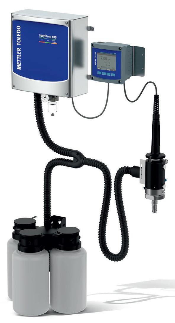
Knowing the conductivity of liquid samples is a key parameter to control product quality throughout the production process.
The optek ACF60 conductivity sensor features a six-electrode, four-pole design. The arrangement of the four current electrodes around the two potential electrodes is designed to result in a more reliable and precise measurement. This design also provides greatly reduced sensitivity to sensor fouling and polarisation. The combination of an optek C800 or C8000 universal converter and the ACF60 conductivity sensor allows a wide dynamic range of 0–10 µS/cm up to 0–850 mS/cm with the same sensor (DIN EN 27888/ISO 7888 and ASTM D1125).
Applications include conductivity control for chromatography processes; pre/post column monitoring of pure, drinking and treatment water; TFF/ultrafiltration; heat exchanger control; and interface detection in food and beverage and CIP processes.
AMS Instrumentation & Calibration Pty Ltd www.ams-ic.com.au
VECOW’s ECX-3200 is a fanless embedded system designed to meet the demands of modern industrial and AI applications. Powered by the 14th Gen Intel Core i9/i7/i5/i3 processors, the system offers a workstation-grade platform with the Intel R680E PCH, supporting CPUs up to 65 W TDP and up to 64 GB of DDR5 4800 MHz memory. With fanless operation, the ECX-3200 is capable of functioning in temperatures ranging from -40 to 75°C, making it suitable for harsh environments. Connectivity is enhanced with four independent 2.5 Gbps IEEE 802.3at PoE+ LAN ports and two 1 Gbps LAN ports.
The system’s expandability features include a PCIe x16 slot that supports up to 200 W power budget, along with multiple M.2 and mini PCIe slots, and optional SUMIT A and B slots. It also includes a USB 3.2 Gen 2x2 Type C port for data transfer rates up to 20 Gbps.
The ECX-3200 supports Intel vPro, TCC, Time-Sensitive Networking (TSN) and TPM 2.0.
Additionally, the ECX-3200 offers the optional VHub One-Stop AIoT Solution Service, leveraging OpenVINO-based AI accelerators for edge AI applications.
Backplane Systems Technology Pty Ltd www.backplane.com.au

Dewesoft has launched of the IOLITE X data acquisition platform. IOLITE X features a high sampling rate of up to 200 kS/s per channel at 24-bit resolution, a Gigabit LAN interface supporting PTPv2 synchronisation and active PoE, and versatile signal conditioning supporting a wide range of measurements including voltage, IEPE, strain (all bridge types), dynamic signals, vibrations, frequency, force, pressure, acceleration, displacement and sound.
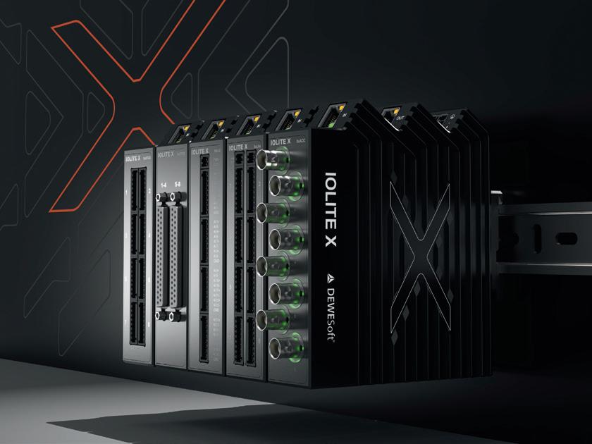
Equipped with a 24-bit delta-sigma ADC and anti-aliasing filter, the IOLITE X achieves a dynamic range of up to 160 dB, and users can easily daisy-chain multiple devices with a single Ethernet cable for power, data and synchronisation, reducing cabling costs and setup time.
An aluminium chassis and fanless design also make the IOLITE X suitable for harsh industrial environments, with an operating temperature range of -40°C to +70°C.
An onboard SD card slot supports up to 2 TB for standalone data logging, making the IOLITE X into an independent data logger. It is also bundled with DewesoftX data acquisition software, providing data visualisation and signal processing features with free lifetime updates.
Metromatics Pty Ltd www.metromatics.com.au
UPS systems play a vital role in the health of your control cabinet: consider these five things before implementing.
Ken Allwine, Associate Product Marketing Manager – Power Supplies, Phoenix Contact USA
The Industrial Internet of Things (IIoT) relies on fast and accurate communication of data. These critical control systems cannot afford a momentary power interruption that could cause a PC or controller to crash. Uninterruptible power supply (UPS) solutions can prevent this type of event.
What types of loads will the UPS be powering — AC or DC? Legacy systems tend to run on AC power, so retrofits of old systems will likely require an AC UPS. In the past 20 years or so, however, the growth of the industrial PC (IPC) market has resulted in a shift to DC power sources.
Next, consider the power and runtime requirements. You’ll need to calculate the proper sizing of the UPS. This is the point where you need to establish realistic expectations. It is easy to say that a 10 A system needs to run for 48 hours. However, realising that system can be quite another task. If a sustained power failure occurs, the job of the UPS is to ensure a safe and orderly shutdown of the control platform to avoid data loss, system crashes or malfunctions. When designing the system, it is important to select a battery sized to allow for some amount of runtime before the PC is told to shut off, or if the main power feed is returned in a reasonable time. Oversized battery systems can also take an extremely long time to recover the charge.

Batteries are the next step in the equation. While there are many battery choices, most UPS manufacturers use a few industry-standardised types. We’ll explore batteries in more detail later, but note that different batteries have different performance characteristics and usable service lives.
With most UPSs, the operator has no way of knowing the battery’s health. Ideally, a UPS will offer multiple types of health indication so the operators can take preventive measures before the battery reaches the failure point.
In control systems that operate on AC voltage, an AC UPS makes the most sense. There are several types of technologies available for an AC UPS.
Offline or standby topology is very straightforward (Figure 1). These products are inexpensive, so they are the most common types of AC UPS. Under normal conditions, an offline UPS passes the mains power from the input to the output without any interaction other than the battery charging circuit in parallel to the mains circuit. If the mains power fails, the UPS will switch over from the mains circuit to the battery circuit. The transfer time from when the UPS loses mains until it produces power from the battery cannot exceed 10 ms. The 10 ms transfer usually does not affect downstream devices, but it is important to consider in systems that are sensitive to voltage fluctuations.
Within the offline segment of AC UPS solutions, there are two subsets: modified (simulated) sine wave output devices and pure sine-wave output devices. These technologies generate the AC output in different ways.
Modified sine-wave devices take the voltage from the battery bank and, in the simplest form, try to create a rough likeness to a sinusoidal wave. While this type of UPS is relatively low cost, it comes with some disadvantages. The massive steps in voltage in the output waveform can damage the input circuits of some downstream devices. These massive steps also create a high number of switching transients from the UPS output. Over time, this can lead to premature failure of the small power supplies in industrial PCs and PLCs.
A pure sine wave UPS produces the same sinusoidal waveform output that would replicate the waveform from the 120/230 V mains power feed. The pure sine wave UPS
is the better choice for sensitive control equipment like PLCs and IPCs. More circuitry is needed to produce this type of output, so this type of system is more expensive. However, the investment will usually pay off, as any control devices powered by the UPS will last longer, resulting in a lower total cost of ownership in the long run.
Mission-critical applications will require an even more advanced UPS, known as double conversion or online UPS (Figure 2). In this topology, the UPS is never in standby mode: the battery circuit is actively connected to the system. If the mains power feed is interrupted, there is no interruption or voltage sag on the output, resulting in seamless battery operation. The online system also has built-in filtering and regulation.
During normal operation, it converts the incoming power feed from AC to DC, and then back again, through an inverter. This level of isolation protects against voltage fluctuations and minor power disturbances on the input side. The higher level of functionality, however, comes with a higher price tag and larger housing.
The drawback of an AC UPS is that everything downstream is AC powered and relies on that single UPS. A control cabinet application might require a very large AC UPS to power all the downstream devices. If that AC UPS fails, so will all the downstream devices. A distributed DC UPS can save cost and space.
Most of today’s control cabinets are now based on DC voltage. An AC UPS backs up and supports everything at the point of entry. With a DC UPS, the backup occurs after the AC/DC power supply.
With this UPS orientation, you can break the loads into buffered and unbuffered loads (see below). The unbuffered loads are the devices that can lose power during a loss of mains voltage and not cause a system
failure. The AC/DC power supply can directly power these loads. The DC UPS would power the devices that perform vital functions, or the buffered loads. This can significantly reduce the load for DC UPSs. This amperage reduction equates to the decrease in the size of the UPS and reduces the size of the needed battery capacity (Figure 3).
DC UPS technology is simpler than AC UPS solutions. DC products do not require AC-to-DC converters or DC-to-AC inverters. All the voltages in the UPS remain at nominal safety extra low voltage (SELV) levels of 24 VDC. This is more efficient for both the power supply and the battery bank. On higher-functioning UPS systems, the only DC conversion that occurs is within the charging circuit for the battery.
A DC UPS system also allows load priority. This prioritises powering the load connected to the UPS. When a UPS is in the mode of supplying the load in mains mode and charging the battery bank, the UPS will monitor the load current. If the load current and charge current combined would cause an overload of the main AC/DC power supply, the UPS will automatically reduce the charge current, preventing an overload.
DC UPSs also tend to be physically smaller than their AC counterparts because they have simpler circuitry. The smaller size can be valuable in a control cabinet with limited DIN rail space.
Some of these advanced, modular DC UPS systems come with built-in diagnostics. While many UPSs have a ‘battery OK’ or ‘system fault’ indicator, the advanced UPS systems can provide real-time insight on system health and functionality. The maintenance team can review the live data about the battery’s heath, voltage level, load current, temperature and more. Instead of guessing about the battery’s health or creating a battery rotation schedule, they have real-time knowledge and can replace the battery before it fails.
A
OCCURS, THE JOB OF THE UPS IS TO ENSURE A SAFE AND ORDERLY SHUTDOWN OF THE CONTROL PLATFORM TO AVOID DATA LOSS, SYSTEM CRASHES OR MALFUNCTIONS.
Batteries are the backbone of a UPS system. When the power goes out, batteries keep things going. So, how can you make sure your battery is not the weak link in your UPS system?
Battery types
Common batteries used in industrial applications include:
Valve-regulated lead acid (VRLA)
• Wide-temperature VRLA
• Lithium-based variants
The standard VRLA battery is the most common for UPS platforms. It is low cost and strikes a balance between cost and capacity, but it lacks durability. The standard batteries have a nominal operational temperature of 0 to 40°C. They perform best in a room with a steady temperature of about 27°C. While they are common in controlled environments, many industrial applications can see temperatures range from -40 to +70°C. This fluctuation will dramatically reduce the lifespan of VRLA batteries.
Wide-temperature VRLA (WTR-VRLA) can be operated from -25 to +60°C. They also
have a slightly longer service life than the standard VRLA. They are often used in outdoor applications. Because the chemistry is different to the standard VRLA, the WTR-VRLA is usually larger and comes at a higher price.
Both VRLA and WTR-VRLA batteries can operate for approximately 250 to 300 charge cycles before they fail. This means a VRLA may only last six months, and a WTR-VRLA may last one and a half to two years before needing replacement.
The lifespan and temperature range of lithium batteries is like that of WTR-VRLA batteries. However, the lithium battery can have up to 7000 charge cycles — a significant increase in service life. Of course, that comes at a higher price. A lithium battery may cost three times as much as a similar WTR-VRLA. Over the course of a lifetime, however, the lithium battery’s performance often pays for itself. Table 1 shows a comparison of these battery technologies.
Because batteries are consumable and the voltage degrades even when they are
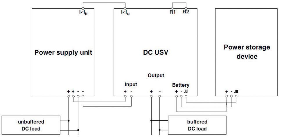
not being used, it is best to purchase and install ‘just in time’ to ensure the freshest battery available. If you store batteries, charge them regularly to maintain their voltage. The smaller the battery capacity, the more frequently the batteries need to be energised and recharged.
After a panel builder completes a cabinet, they often forget about it. If the battery sits dormant during transit or storage, it will degrade. If the fuses are not disconnected, parasitic loads can drain the battery. The ideal solution is to remove the battery from the cabinet after factory acceptance testing and keep that battery as a test battery for multiple cabinets. When you are ready to commission the machine, install a fresh battery.
The IIoT means the industrial world is more connected than ever before, making all types of devices smarter. The UPS is no exception. With networking and connectivity, you can have access to your UPS performance data at any time or place.
To connect to these UPSs, there must be a network in place. EtherNet/IP, Profinet and Modbus TCP are among the most common networking protocols for industrial networks. A UPS that communicates over these protocols will give the end user visibility into battery performance wherever the UPS is installed.
A UPS with advanced monitoring and diagnostics can help an engineer or technician make intelligent decisions about UPS or battery maintenance. With warning alarms and real-time information about the battery’s state of health, it’s possible to take a proactive approach to battery maintenance. Having this data readily available eliminates ‘battery anxiety’ and unnecessary maintenance.
UPS systems play a vital role in the health of your control cabinet. With these tips, you are better prepared to choose the UPS system that meets the needs of your application. The bypass is active during startup

The pricing and capabilities for different types of logic solvers for Safety Instrumented Systems (SIS) can vary widely. This not only pertains to the initial expense of purchase, but also for the implementation of and lifecycle costs in maintenance and programming. The most common determining factors in choosing which logic solver best fits a safety application are loop and point counts, communication requirements, and the complexity of logic required for safety mitigation.
When dealing with high-density point and loop counts in a centralised location where there is interdependency on various points and loops, a larger more complex logic solver such as a safety PLC may be the best choice. Larger systems like these more easily afford themselves to more complex control logic and voting schemes with high reliability across a multitude of loops with several points. If points are not centralised, many of these larger safety systems can be networked together for fl exibility in cross-communication, as well as for future expansion. The tradeoff is that the initial costs of purchase, programming, and installation for a larger safety system or PLC can be very expensive — tens of thousands of dollars and much more, not to mention the high lifecycle costs. Most larger safety systems often require programming modifications by a highly trained and skilled safety system programmer.
For scenarios where only one or a few points need to be monitored in a single Safety Instrumented Function (SIF), a much less expensive and complex single loop logic solver can be a very eff ective choice. An example of this type of application would be simple on/off functionality for pump/valve control when fi lling, emptying, or preventing overflow in a container or tank. Single loop logic solvers — also known as alarm trips — have made significant strides in their capabilities since they were first installed in SIS applications. These advanced capabilities include programmable inputs, local configuration using onboard controls, safe password protection, process display and comprehensive internal, input and sensor diagnostics. Single loop logic solver output relays can also be wired in series to provide voting architectures, but this requires extra field wiring and comprehensive wiring schematics. And while that may not be an overly complex task, if the voting logic changes, meticulous rewiring of relays and rewriting of proof test procedures will follow. Standalone single loop logic solvers are of course less
expensive and easy to program but are quite limited in their ability to handle multiple loops, accept multiple inputs, perform logic or internal voting, or provide digital communication with a process control system or other host system.
In the wide space that exists for applications that require higher density loop/point counts with more advanced logic and loop monitoring than a single loop logic solver can handle, the SLA Multiloop Logic Solver and Alarm may be a more effective and better-sized fit for many SIFs. Like the larger safety systems and PLCs, the standalone SLA includes 17 I/O points, handles one to three SIF loops, performs logic and math equations, and offers signifi cant fl exibility for voting architectures at a fraction of the cost and complexity of larger safety systems and PLCs. The SLA harnesses the cost and configuration simplicity of single loop logic solvers, but also offers much of the advanced functionality of the larger safety systems and PLCs, albeit at smaller loop and point counts. The SLA can potentially meet many of the SIS applications that once required safety PLCs, but also offer an advancement in functionality and capability at an attractive price point.
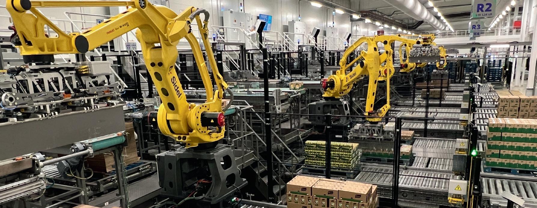
Unilever is one of the world’s leading FMCG companies with sales in 190 countries and products used by 3.4 billion people every day. Its nutrition factory in Ploiesti, Romania manufactures products for one of the company’s most well-known brands, Knorr.
The entire dry nutrition range includes meal makers, dish and sauce bases, and seasonings among others, in various packaging formats: pouches, bags, cartons and multipacks. These different product lines also handle a large variety of secondary packaging options — American boxes, tray and hood, tray and shrinking foil, and shelf-ready packaging.
Unilever Ploiesti’s production capability has gradually evolved. Volumes have tripled from 12,000 tons per year to 35,000 tons per year; SKUs have risen from 200 to 1000; packaging lines increased from 14 to 28; and personnel has jumped from 200 to 700. It was no longer feasible to utilise the factory’s existing end-of-line system to manage the breadth of brands packed onsite. Unilever Ploiesti has therefore invested in a new central palletising solution.
Sidel installed a centralised palletising system comprising eight robotic cells; several hundred metres of case and pallet conveyors; four pallet handling shuttles; and two stretch wrappers, achieving a production rate of up to 98 pallets an hour. The consolidated system is connected to 28 packing lines.
The robotic cells are divided into two separate clusters — one with five robots, and the other with three. Each cluster has one central pallet magazine for all pallet types and sizes, one induction shuttle for full pallet discharge and one compact shuttle for empty pallet delivery integrated underneath the robotic islands.
According to the capacity of each packing line and the palletising pattern requested, the cells have three or four product infeeds, ensuring a robot utilisation rate of 92%.
Unilever’s masterplan for the Ploiesti site was to keep the palletisation space in a separate area from the packing hall to easily accommodate the recurring packing line modifications. To connect the two areas, Sidel proposed a high-level conveying solution with spiral elevators to save space, facilitate circulation and increase the overall flexibility linked to site transformations.
“We’ve been impressed by Sidel’s design capability to fit the detailed palletising specifications we required in a compact area and simultaneously oversee the complexity and high throughput coming from the packing lines,” said Iuliana Popescu Colt, Operations Manager at Unilever.
Sidel was able to demonstrate its proposed arrangement using virtual reality glasses, allowing Unilever to visualise the full installation, check the space constraints and solve potential issues related to platforms, the operators’ access and the raw material flows. Speed simulations also helped to confirm the speed levels and the robot utilisation rate.
After the design phase, Sidel’s project management spanned from factory acceptance testing to site installation. All eight robot cells were completed in less than eight months. The modular concept accelerated installation as each cell was commissioned individually and at once integrated into the factory’s live packaging operations.
“Spending a little bit more time in design and simulations helped during the installation phase. The virtual model fitted exactly in the physical space, so that we achieved the desired throughput in a very short time,” said Laurentiu Badulescu, Technical Manager at Unilever.
The central palletising system is integrated in the Unilever digital process. As soon as the operator selects the production order from the packing line, all the information related to the palletisation, including pallet size, type of pattern, number of rows/layers, and the label to apply is all automatically set and transmitted to the corresponding palletising cell and the entire end-of-line setup.
“This was a complex project; however, the solution developed by Sidel is based on standard proven modules, which have been developed and implemented in other projects,” Badulescu said. “Sidel has combined them in a smart way to deliver a custom solution, avoiding any complex start-up issues brought by a made-to-order one-shot solution.”
Sidel Oceania Pty Ltd www.sidel.com

Ella Averill-Russell, IICA Sydney Branch Manager
The integration of smart technology into industrial machinery and robotics has revolutionised workplace safety, significantly reducing accidents and enhancing operational efficiency. Advanced sensors, artificial intelligence (AI), machine learning (ML) and the Internet of Things (IoT) collectively create a safer working environment.
Real-time monitoring and predictive maintenance
Smart technology improves safety through real-time monitoring and predictive maintenance. Advanced sensors in machinery collect data on parameters like temperature, vibration and pressure, and AI and ML algorithms analyse this data to predict potential failures before they occur. Early anomaly detection allows for proactive maintenance, preventing unexpected breakdowns that could endanger workers.
Predictive maintenance extends equipment lifespan and ensures machinery operates safely, minimising the likelihood of catastrophic failures leading to accidents.
Smart technology enhances human-machine interaction, reducing risks where humans and robots work closely. Collaborative robots, equipped with sensors and AI, detect human presence and respond accordingly. For example, if a worker enters a cobot’s operational area, the robot can slow down or stop to prevent collisions.
Augmented reality (AR) and virtual reality (VR) technologies also provide immersive training experiences in simulated environments. Workers learn to interact with machinery safely without the risks of on-the-job training, becoming more familiar with safety protocols.
Modern machinery incorporates advanced safety features enabled by smart technology. Emergency stop mechanisms, connected to central monitoring systems, can be activated instantly in case of danger. Smart sensors detect hazardous conditions like gas leaks, fires or chemical spills, triggering automatic shutdowns and alerting workers to evacuate.
These features significantly reduce injuries or fatalities by ensuring rapid responses to emergencies and preventing dangerous situations from escalating.
Ergonomics is crucial for worker health and safety, and now smart technology is helping to optimise ergonomic design, reducing physical strain on workers. For example, AI-powered exoskeletons can assist in lifting heavy objects, minimising musculoskeletal injuries.
Wearable smart devices can also monitor workers’ health in real time, tracking vital signs like heart rate, body temperature and fatigue levels. If a worker shows signs of excessive fatigue or stress, the system alerts supervisors to take necessary actions, such as providing breaks or adjusting workloads.
Smart technology generates vast amounts of data that can be analysed to identify trends and improve safety protocols. Companies can gain insights into the causes of accidents and near-misses, allowing them to implement targeted safety measures. For example, data analysis might reveal that a particular machine model has a higher failure rate, prompting a redesign or additional safety features. Data-driven safety improvements ensure that safety measures are continually refined based on real-world performance, leading to safer working environments.
Conclusion
The integration of smart technology in machinery and robotics has significantly enhanced industrial safety. As technology advances, the potential for further safety enhancements is immense, promising a future where industrial accidents are minimised and worker wellbeing is prioritised.
August
IO-Link Live: Solutions for Modern Manufacturing
21 August 2024
Bürkert Australia, 15 Columbia Way Norwest Business Park
iica.org.au/Web/Web/Events/Event_Display. aspx?EventKey=IICABURKRT
IICA Technology Expo Sydney 28 August 2024
Rosehill Gardens iica.org.au/Web/Web/Events/Event_Display. aspx?EventKey=IICASYDNSW
September
Industrial Net Zero Conference 2024
3–5 September 2024
Aerial UTS Function Centre www.industrialnetzeroconference.com.au/ IICA TÜV Functional Safety Engineer SIS
Training – Melbourne
3–6 September 2024
Novotel Melbourne Central, Melbourne iica.org.au/Web/Web/Events/Event_Display. aspx?EventKey=TUV3SEP
October
WA Mining Conference & Exhibition
9–10 October 2024
Perth Convention & Exhibition Centre www.waminingexpo.com.au/en-gb.html
IICA Technology Expo Devonport 16 October 2024
Paranaple Convention Centre iica.org.au/Web/Web/Events/Event_Display. aspx?EventKey=IICADVPTAS
ICS Cyber Security Conference 21–24 October 2024
Intercontinental Buckhead Atlanta, GA www.icscybersecurityconference.com/
All Energy Australia 23–24 October 2024
Melbourne Convention and Exhibition Centre www.all-energy.com.au/en-gb.html
Workplace Health & Safety Show 23–24 October 2024
Sydney Showground, Olympic Park whsshow.com.au/whats-on-sydney
IICA Technology Expo Griffith 29 October 2024
The Shed Yoogali iica.org.au/Web/Web/Events/Event_Display. aspx?EventKey=IICAGRFNSW
International Mining and Resources Conference + Expo (IMARC) 29–31 October 2024
ICC Sydney imarcglobal.com
The rise of artificial intelligence (AI) has unlocked multiple efficiencies and scaled-up processes for manufacturers and is seen as particularly useful in the field of condition monitoring.
Condition monitoring — the process of monitoring changes to a piece of equipment’s condition — is primarily used to detect developing issues or faults and prevent a possible breakdown. Applying AI to this process has allowed condition monitoring to become increasingly sophisticated, with some researchers estimating that AI-enabled condition monitoring can predict equipment failures with a 92% accuracy rate.
More accurate condition monitoring is enabled through AI’s advanced data analysis capabilities, integrating and analysing data from multiple sources like sensors, temperature gauges and cameras, all in real time. This ability to process multiple data streams simultaneously allows AI to extract insights and trends from the data, as well as allowing for the swift detection of anomalies.
AI-enabled condition monitoring also improves predictive maintenance — a crucial benefit when considering that unplanned downtime costs manufacturers an estimated US$50 billion annually.1 Predictive maintenance is intended to reduce the risks of unexpected machinery failure or breakdown by flagging when time-sensitive maintenance is needed.
With the help of AI-enabled condition monitoring, manufacturers can not only prevent unexpected breakdowns, but also better understand the root causes of potential issues. This can also keep costs down by scheduling maintenance only when needed, avoiding unnecessarily time-consuming and expensive repairs.
We’re also seeing an increasing number of manufacturers employing AI tools to estimate the remaining lifespan of a particular asset, which enables better budgeting and inventory management, as well as ensuring minimal downtime while newer models are ordered.
The benefits unlocked by integrating AI into condition monitoring processes are further enhanced when applied to a condition monitoring tool. A good condition monitoring tool will include hardware and integrated software that can automatically collect and evaluate data from the IO-Link sensors.
Since any IO-Link sensor can be used, and the base unit doesn’t require a connection to the machine controller, a manufacturer employing condition monitoring systems shouldn’t have to adapt their existing systems, only supplement them. The onboard AI can be trained to learn ‘normal’ machine operation and to detect deviations and anomalies beyond simple thresholds.
So, while we’ve touched on the real-life applications of AI in condition monitoring and the tools currently available that allow for the seamless and fast integration of AI onto your factory floor, allow me to get futuristic for a moment. I’m talking, of course, about automated maintenance.
As AI capabilities continue to advance, we may soon start seeing an increase in equipment fitted with AI-based tools that enable automated maintenance — allowing equipment to self-repair without human intervention.
The possibilities of this are endless, ranging from tools that allow for self-diagnosis of machine condition and possible issues, automatic resetting of parameters as needed and, in the most extreme example, self-repairing of components. IIoT-enabled machines will also be able to communicate with other machines on the network, requesting assistance if necessary.
While fully automated maintenance through AI is still a way off, it will eventually be an extremely effective tool in reducing the probability of human error, and maintenance and downtime costs.
1. IndustryWeek and Emerson 2016, Unlocking Performance, <<https://partners.wsj.com/emerson/unlockingperformance/how-manufacturers-can-achieve-top-quartile-performance/>>

*Jim Wallace is the Sales Director of Balluff Australia & New Zealand and a member of the Open IIoT cohort. He regularly contributes for features about Industry 4.0 and Smart Automation in Manufacturing.
Westwick-Farrow Media
A.B.N. 22 152 305 336 www.wfmedia.com.au
Head Office Unit 5, 6-8 Byfield Street, North Ryde
Locked Bag 2226, North Ryde BC NSW 1670 AUSTRALIA
ph: +61 2 9168 2500
Editor Glenn Johnson pt@wfmedia.com.au
Managing Editor
Carolyn Jackson
Publishing Director/MD
Janice Williams
(Shy &) Retiring Proofreader: Deborah Bailey
Art Director/Production Manager
Linda Klobusiak
Art/Production Marija Tutkovska
Circulation
Alex Dalland circulation@wfmedia.com.au
Copy Control
Ashna Mehta copy@wfmedia.com.au
Advertising Sales
Sandra Romanin – 0414 558 464 sromanin@wfmedia.com.au
Tim Thompson – 0421 623 958 tthompson@wfmedia.com.au
If you have any queries regarding our privacy policy please email privacy@wfmedia.com.au
Information