
13 minute read
3.3 Gordon. Designing A Rubber Band-Powered Plane To Uncover Aerodynamics
22
able to be used to discriminate between fish from different geographic regions.
Advertisement
Acknowledgements
We would like to express our gratitude to our project advisor, Andrew McGuier, for his guidance and useful critiques of our work, as well as Johnathan Stephenson for his encouragement and supervision of our project. Our special thanks are extended to Dr. Natalie McGuier, who assisted throughout the project. We would also like to thank the contributors to the NIH GenBank, as well as the maintainers of the Ribosomal Database Project and the Sequence Manipulation Suite. Lastly, we wish to thank Dr. Barry Luokaala and the sponsors of PGSS, Carnegie Mellon University and the Mellon College of Science, and the PGSS Alumni Association for their part in making our research possible.
References [1] Centers for Disease Control and Prevention. Salmonella Outbreak Linked to BrightFarms Packaged Salad Greens. 2021. URL: https : / / www . cdc . gov / salmonella / typhimurium - 07 - 21 / index.html (cited on page 17). [2] J. M. Janda and S.L. Abbott. 16S rRNA Gene Sequencing for Bacterial Identification in the Di-
caption graphicx Chapter 3. Life Science
agnostic Laboratory: Pluses, Perils, and Pitfalls. 2007. URL: https : / / doi . org / 10 . 1128 / JCM . 01228- 07 (cited on page 17).
[3] Z.J. Jay and W.P. Inskeep. The Distribution, Diversity, and Importance of 16S rRNA Gene Introns in the Order Thermoproteales. 2015. URL: https: / / doi . org / 10 . 1186 / s13062 - 015 - 0065 - 6 (cited on page 17).
[4] I Slav. Oil-Eating Bacteria Could Help Clean
Up the Next Oil Spill. 2018. URL: https : / / www . businessinsider . com / oil - eating bacteria - could - help - clean - up - the next- oil- spill- 2018- (cited on page 21).
[5] Spectrum Compact CE System. Promega Corporation. URL: https : / / www . promega . com / products/sequencing/sanger- sequencing/ spectrum - cce - instrument / ?catNum =
CE1304 (cited on page 17).
[6] L.A Stark. Beneficial Microorganisms: Countering
Microbephobia. 2010. URL: doi : 10 . 1187 / cbe . 10- 09- 0119 (cited on page 17).
[7] N Tsevdos. Yogurt. Food Source Information. 2020. URL: https : / / fsi . colostate . edu / yogurt/ (cited on page 17).
By Tommy Gordon ’23
Although putting together a small (about 50 cm long) rubber band-powered plane may seem like a trivial science class activity or a simple individual project, it is an endeavor that is made surprisingly tricky due to the numerous forces and phenomena in action during flight. Throughout the past few months, I have been in the process of constructing several aircraft for an event named “Wright Stuff”, one of many that make up the Science Olympiad competition. Planes constructed for this event generally follow a standard design with a nose-mounted propeller, the main wing, and the empennage (the tail structure consisting of the vertical stabilizer and horizontal stabilizers). Below are some diagrams of my initial aircraft designs (Figures 1-3): Figure 1
3.3 Gordon. Designing A Rubber Band-Powered Plane To Uncover Aerodynamics 23

Figure 2

Figure 3
Starting from the front of the aircraft, we have the propeller. Ideally, the center of mass would be located about 1 3 of the way down the main wing (starting at the leading edge), and therefore, like all other parts added to the aircraft, the weight must be taken into account.
In addition to weight, the nose-mounted propeller’s centered position can cause the aircraft to turn slightly to the left or right (depending on what direction the propeller is moving). Both the torque effect and the slipstream/ corkscrew effect illustrate this left/ right turning tendency. The torque effect explains that as the propeller rotates in one direction, the aircraft is pulled in the other direction (on the horizontal axis or yaw). This phenomenon can also be explained by Newton’s third law of motion: for every action, there is an equal and opposite reaction [1]. The slipstream/ corkscrew effect is also related to the spinning of the propeller. When the propeller spins at high speeds, it acts like a wing, pushing accelerated air backward to propel the plane forward. This backward air; however, travels in a spinning pattern matching that of the propeller down the fuselage until it hits the vertical stabilizer (the aircraft component with the highest amount of surface area from the side) causing the plane to turn. The Figure 4 illustrates the torque effect and the fifth the slipstream effect. Figure 4
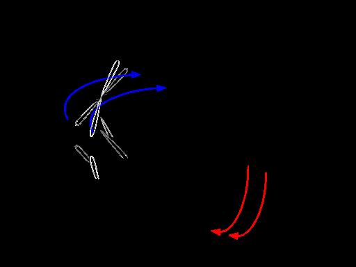
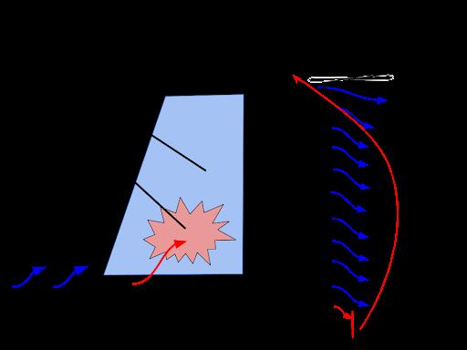
Figure 5
The torque and slipstream effects are also the primary reason for deciding to have the aerofoil positioned above the fuselage as seen in Figure 2. The aerofoil can avoid the majority of disruption caused by the slipstream and torque effects with its positioning further above the fuselage.
Following the propeller, is the wing or aerofoil. This is the most critical part of the plane as it is responsible for producing lift; the force that pushes the aircraft upwards.
24

Figure 6
Bernoulli’s principle explains why an aircraft can produce lift (due to the shape of the aerofoil). It states, “For horizontal flow, an increase in velocity must be accompanied by a decrease in pressure” [4]. When an aircraft aerofoil passes through air particles, the particles below the wing flow at a slower rate than those above the wing, therefore, decreasing the pressure above the wing and increasing the pressure below. The pressure difference formed produces lift. Figure 7 shows Bernoulli’s principle in action as the particles above the wing (aerofoil) move at greater speeds.
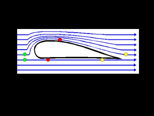
Figure 7
Note: • Green: Air molecule position at t = 1 • Red: Air molecule position at t = 2 • Yellow: Air molecule position at t = 3
This situation can also be proven with Bernoulli’s equation (Figure 8). The subscripts 1 and 2 denote the Chapter 3. Life Science
values taken at two different points (at the leading edge and the trailing edge of the wing in this situation). Assuming the plane is flying in a forward direction and there is no change in elevation, the terms ρ gh1, ρ gh2, P1, and P2 cancel out. The terms ρ gh1 and ρ gh2 account for ρ , (air density), g, (acceleration due to gravity), and h, (the elevation at each point). Since all of these values are equivalent, they can therefore be canceled out. The terms P1 and P2 account for the pressure of air at the elevation of both ends of the wind; however, as stated earlier, the plane’s elevation is not changing. Therefore, the air pressure is the same at both points [3].
P1 + 1 2 ρV 2 1 + ρ gh1 = P2 + 1 2 ρV 2 2 + ρ gh2
Figure 8: Bernoulli’s Equation
After the ρ gh and P terms have been canceled out, Bernoulli’s equation is stating that one-half the density of air (ρ ) times velocity squared (V 2) is equivalent at both points. This equation also illustrates the conservation of energy as velocity and pressure will always be inversely proportional. When on one side of the equation the pressure is high, the velocity is low and vice versa for the other side.
Apart from the shape of the aerofoil shape, the wing has several other key design aspects that increase lift and stability while minimizing drag. These design aspects include an appropriate angle of attack, dihedral, and winglets. As seen in Figure 2, the angle of attack of the plane is approximately 14 degrees. The angle of attack is the angle formed by the chord (straight line between the leading and trailing edge of the wing) and the oncoming flow of air as the plane moves forward.
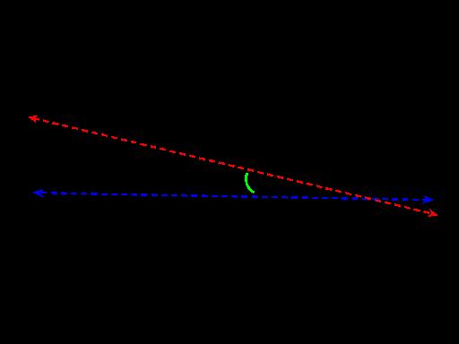
Figure 9
3.3 Gordon. Designing A Rubber Band-Powered Plane To Uncover Aerodynamics 25
The angle of attack works to generate additional lift by directing the flow of air further downwards producing an upwards force. It takes into account the Coanda effect. The Coanda effect is the tendency of air to remain close to or attached to the upper surface of the wing, even during the downwards slope near the trailing edge (represented by Figure 10).
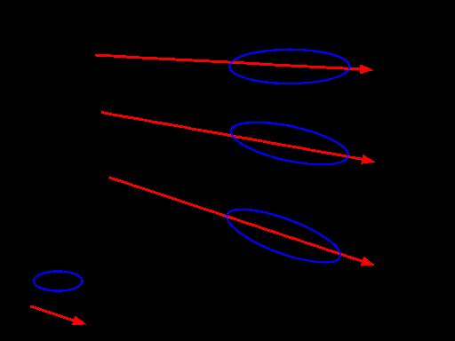
Figure 10
As seen in the figure above, as the angle of attack gradually increases, so does the direction of airflow and therefore lift. With this said, when the angle of attack becomes too great, the Coanda effect wears off, and the plane stalls. Figures 11 and 12 show how beyond an approximate angle of attack, airflow will separate from the wing’s upper surface and the plane will start to stall. This separation is called cavitation, and if the angle of attack exceeds approximately 16 degrees, the plane will slowly approach a stall and lose lift.
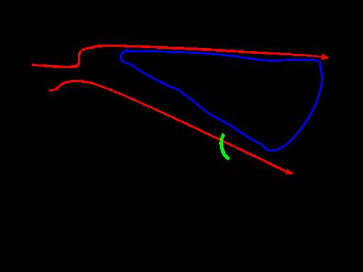
Figure 11 [2]
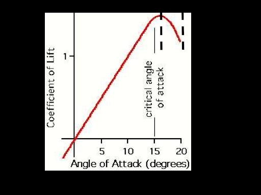
Figure 12
In reference to Figure 3, the aircraft has a slight dihedral. This means that both wings are angled slightly upwards. Adding a dihedral to an aircraft increases its roll stability. In other words, it reduces the tendency of an aircraft to bank from side to side in an uncontrolled manner. Whenever a plane with a dihedral sideslips (moves left or right and down in a certain direction), it will gradually roll back to a level flight.
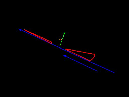
Figure 13
As seen in Figure 13, as the plane rolls towards one side, the wing that has moved downwards has a higher angle of attack in relation to the upwards wing. Since the plane has sideslipped, the relative airflow is also approaching from the right side, and therefore, in relation to that airflow, the right-wing has a higher angle of attack. When meeting the airflow from the right, the greater angle
26
of attack and lift generation of the right-wing will level the plane back out on the roll axis [5].
The final major design element of the wing are the winglets at the end of each wing. These are the tips of the wings of the aircraft and they are configured in a more extreme upwards angle in comparison to the dihedral.

Figure 14
Although the dihedral improves roll stability on the aircraft, it can also assist in accentuating vortices that appear on the tips of the wings. Vortices are like small tornadoes that form when the high-pressure air below the wings moves towards the low-pressure air at the top of the wing near the wingtip. These vortices produce induced drag (induced meaning it is inevitable drag produced by lift). In addition to the fact that fluids always travel from high to low-pressure regions, the dihedral also makes this travel easier for the high-pressure air.
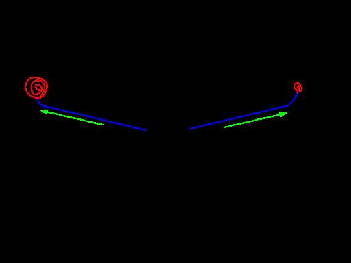
Figure 15 Chapter 3. Life Science
The winglets reduce the surface area of the tips of the wings and introduce a sharp upward slope which reduces the amount of high-pressure air mixing with low-pressure air. In turn, the vortices are greatly reduced in size. The shape of the winglet also allows for the high-pressure air to accelerate to a lower-pressure state by the time it reaches the tip of the winglet.
Another way to decrease the size of vortices (induced drag caused by lift), is to have wings with a larger aspect ratio. The aspect ratio of a wing is the ratio of the chord to the wingspan or the wingspan divided by the chord [5].
Figure 16
Although many types of aircraft have structural limitations when it comes to increasing wing size dramatically, larger aspect ratios are present in planes such as gliders, which attempt to maximize flight time by minimizing drag (achieved by a high aspect ratio).
The final major component of the aircraft is the empennage or the tail structure. The tail structure is composed of vertical and horizontal stabilizers. The vertical stabilizer assists with stability across the yaw axis (left and right) and the horizontal stabilizers across the pitch axis (up and down). While the empennage has less complex design aspects than the wing, it still maintains a critical role in aircraft stability and control. The airplane diagrammed in Figures 1-3 includes conventional tail design (with a singular vertical stabilizer between two horizontal stabilizers). When designing a tail, one of the most important things to take into account is weighting. If the tail is too light, the plane may go into a nosedive, and if it is too heavy, it may enter a stall and produce no lift. In addition, the horizontal stabilizers also have aerofoil designs meaning they produce lift.
3.3 Gordon. Designing A Rubber Band-Powered Plane To Uncover Aerodynamics 27
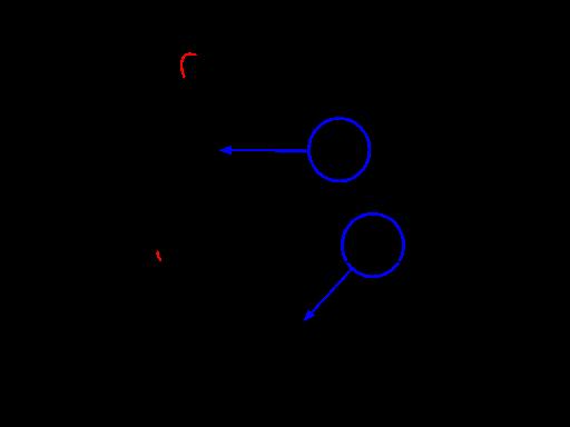
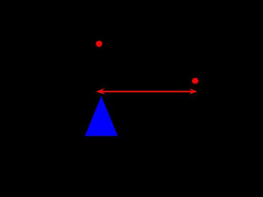
Figure 17 Figure 19
Properly balancing the aircraft requires knowing the tail arm, or the distance from the center of gravity to the aerodynamic center (center of lift) of the tail.
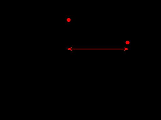
Figure 18
The tail arm works like the fulcrum on a lever [6]. The fulcrum is positioned below the center of gravity and at one end you have the weight of the main wing and forces that act upon it. On the other end, you have the weight of the empennage and forces that act upon it.
This situation resembles a lever. Each side of the lever is varying in distance meaning mechanical advantage will be at play. The shorter side has a lot of weight due to the main wing and a significant amount of force is produced by this wing, while the longer side of the lever contains less weight (lighter empennage) and has less force acting upon it. Therefore the plane should be balanced upon the fulcrum in an ideal situation.
From the slipstream effect created by the propeller to the way Bernoulli’s principle describes how an aircraft creates lift, there are many complex forces interacting with an aircraft when it flies. Although these are some of the basic ones, it is crucial that they are all taken into account even when designing a small rubber band-powered aircraft. If you ever find yourself constructing one of these small airplanes in the future for a science project or just for fun, take a minute to think how all of the seemingly insignificant design choices can affect an aircraft’s performance. Or if you find yourself traveling somewhere on a much larger aircraft, think about how all of these concepts are at play during your flight.
References [1] URL: ol- january- iap- 2019/class- videos/ lecture - 2 - airplane - aerodynamics/ (cited on page 23). [2] Angle of Attack. URL: https : / / www . researchgate . net / figure / Coefficient of - Lift - versus - critical - AoA - Source wwwaviation - historycom _ fig3 _ 336286742 (cited on page 25). [3] Bernoulli’s Equation. URL: https://www.quora. com / What - are - the - limitations - of - the Bernoulli- Equation (cited on page 24).


