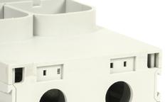
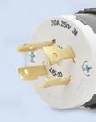
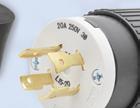
• GR-REC4-GFCI uses one GFCI duplex receptacle that protects all four circuits
Starting at $48.00 (GR-REC4)
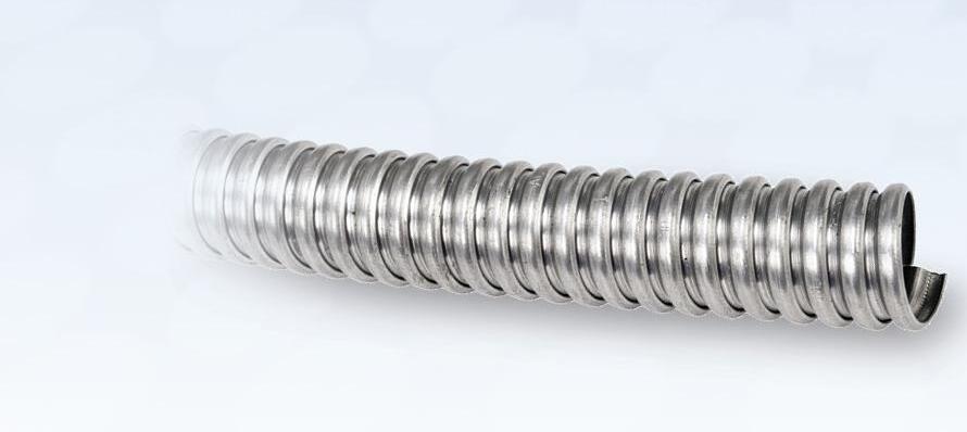
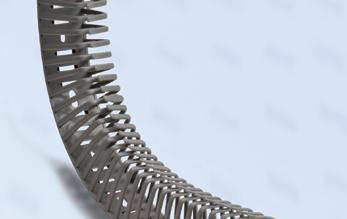
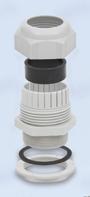
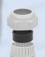
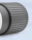
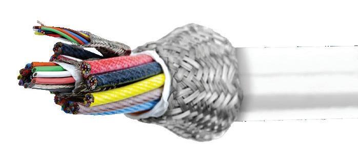
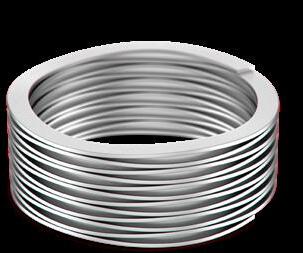
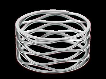
Southwire Flexible Metal Conduit
Southwire flexible metal conduit shields electrical wiring while its flexible spiral construction allows for smooth and efficient installation.
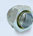
• Alflex™ Type RWA (Reduced Wall Aluminum) is manufactured with a lightweight, high-strength aluminum alloy with built-in flexibility for simplified positioning
New Gladiator GR series DIN rail or panel mounted quad-port power receptacles provide convenient outlets used in electrical enclosures to temporarily power laptop computers and test equipment.
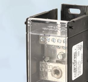
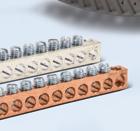
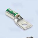
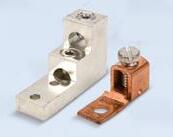
Penn Union Power Distribution and Splicer/Reducer Blocks
Penn Union power distribution blocks feature a modular design that allows for various multi-pole block configurations, providing distribution of power from a single source to various loads. The splicer/reducer blocks allow for in-line splices or conductor size reductions.
• Galflex™ Type RWS (Reduced Wall Steel) is manufactured with a galvanized, corrosionresistant, high-strength steel alloy to provide reliable mechanical protection for conductors and cable
• Up to 100kA SCCR rating
• DIN rail mounting options
• Up to 1000 VAC/1000 VDC UL ratings
• IP20 finger-safe protection rating
Starting at $14.00 (38049AL)
&
Starting at $22.00 / 25ft. coil (55082021)
FTG Enclosed Power Distribution and Terminal Blocks
FTG enclosed power distribution blocks feature a modular design, are suitable for branch and feeder circuits, and are available in ratings up to 380A. The enclosed terminal blocks offer convenient connection options in ratings up to 840A.
• Rugged aluminum construction
• Dual copper/aluminum conductor ratings
• DIN rail or panel mounting
Starting at $17.00 (ASRB-11-2/0-1)
Visit our website to see our full Wiring Solutions o ering
One of the more interesting site visits I’ve been on was a recent tour of Celebrity Cruises’ forthcoming ship, the Celebrity Xcel, at shipbuilder Chantiers de l'Atlantique’s drydock in Saint-Nazaire, France. The facility is the largest assembly dock in Europe, with 3,800 employees and another 6,200 contractors on site.
Shipbuilding is a complicated process. Even within Classes of ships, the individual cruise ships vary somewhat. Once the ships are put into service, the company receives feedback on everything and from everyone — from the crew to the engineering team to the passengers.
Modularity is a key. The actual construction work starts on dry land, as the first steel is cut, and these large pieces of the hull are welded together into what are called blocks. Eventually, different blocks are loaded into the drydock, a large berth that can be flooded with water later in the construction process. Putting the ship together is like working with enormous Lego pieces. More than 40 blocks comprise the ship; these are built individually on land and eventually moved into place with enormous cranes. Then, they’re connected and welded together, and work inside continues until the next piece is finished.
This process is very much the opposite of a manufacturing assembly line. They’re building one ship that’s unique in many ways, even if it has past siblings from the same Class. Restaurants and public areas and even overall sizes can vary.
Yet, the construction of the crew and passenger cabins is very much a traditional assembly line process. You
need hundreds of specific types and sizes of cabins, so the work here is very repetitive and predictable. Cabins are built as 80% finished products that are eventually hoisted onto the ship’s superstructure and “plugged in” once installed.
Chantiers de l'Atlantique has a virtual engine room area, where early in the design process, engineers can move around in a 3D simulation of the engine room to coordinate piping, cabling, equipment, and componentry. Here, Smart Mind is used as the CAD program. The team then uses Unity (a crossplatform game engine) to take the Smart drawings and view them through the virtual reality goggles.
For the cabin design, which also happens on site, Solid Edge is used, said Eric Perennou, senior project manager of Edge Class.
“Solid Edge is useful when you have plenty of parts to specify, as per the cabins,” he said. “It was chosen for this reason and because it was easy to interface. Also, for the production, it was helpful. There are many areas where we don’t build [the subsystems] ourselves, so here we don’t need detailed bills of materials. And Solid Edge allows us to have easier access to the volumes of a space, as well as the settings, the lighting, and so on.”
I came away impressed in how one project can so seamlessly include both assembly line work and custom, one-ofa-kind manufacturing. And that’s good to keep in mind for your next big project. Sometimes the answer isn’t one way of doing things, but a blend of very different processes. DW
Paul J. Heney - VP, Editorial Director pheney@wtwhmedia.com
On X (formerly Twitter) @wtwh_paulheney
CONTROL
encoder processor capabilities
Encoders increasingly leverage hardware and software to allow dynamic setting changes (including those to resolution and output circuit type) as well as reporting of current conditions and predictive-maintenance data
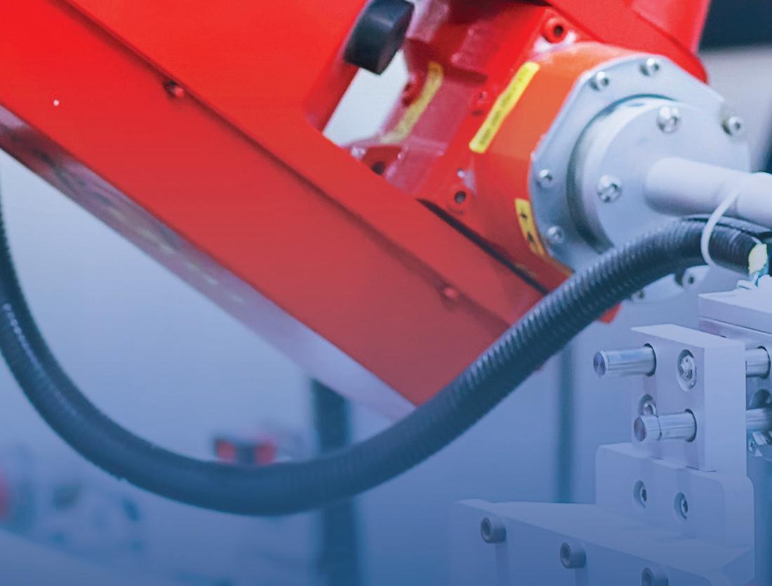
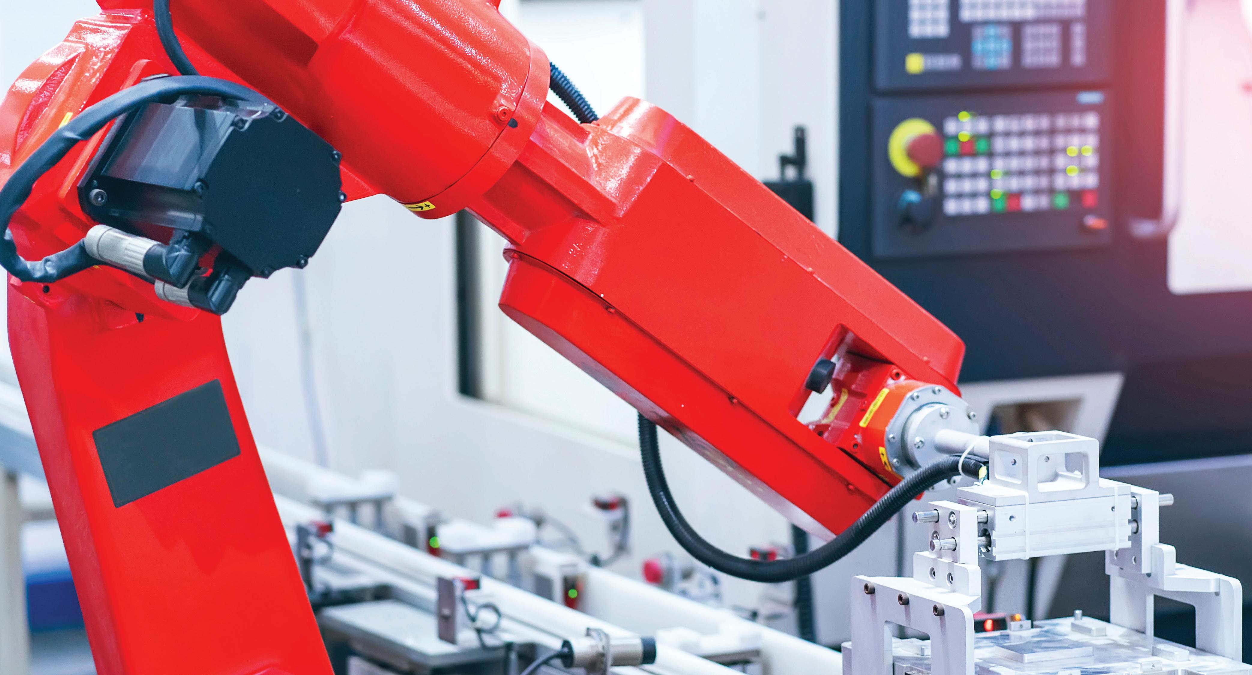
A review of the different types of linear actuators reveals how to choose the best solution based on the particular application requirements.
Bit jitter can be a problem. A digital data stream is composed of a series of rapidly changing “ones” and “zeros.” Bit jitter can make it difficult to tell the difference, resulting in data errors.
A thermal connector, sometimes called a cold-end termination, is designed to connect temperature sensors to measuring instruments, like thermocouples or resistance temperature detectors (RTDs).
Nippon
These
EDITORIAL
VP, Editorial Director Paul J. Heney pheney@wtwhmedia.com
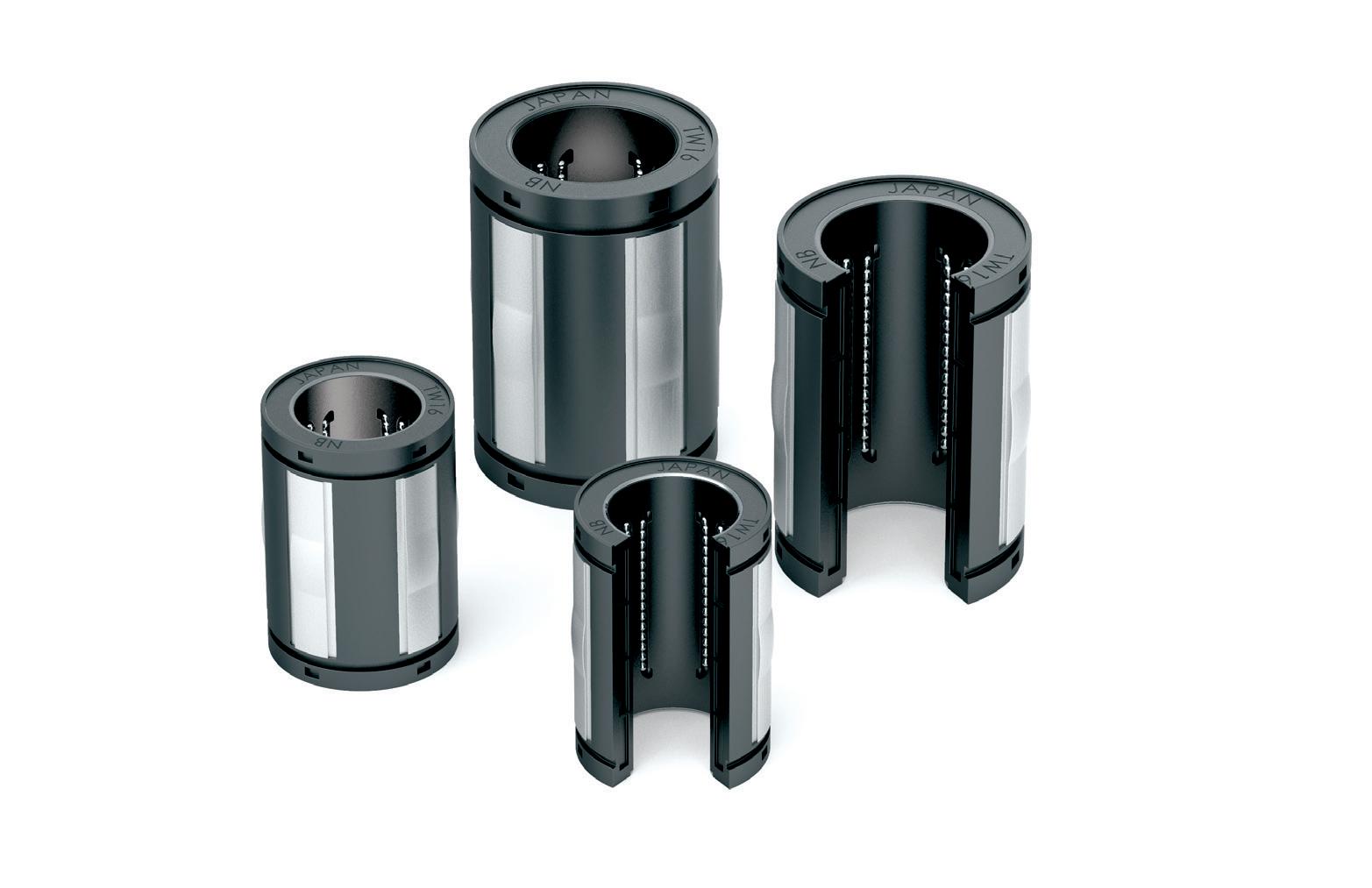
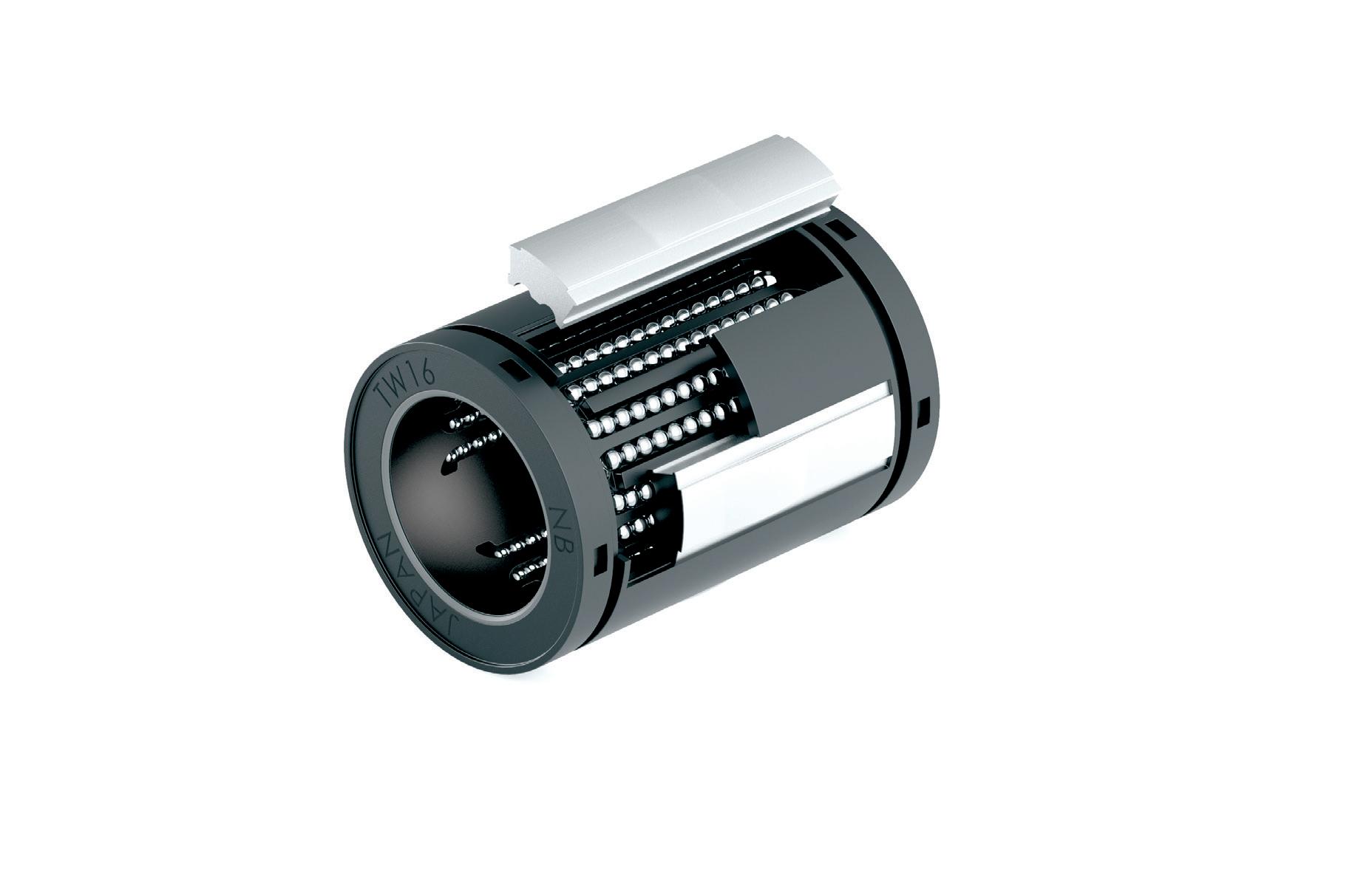
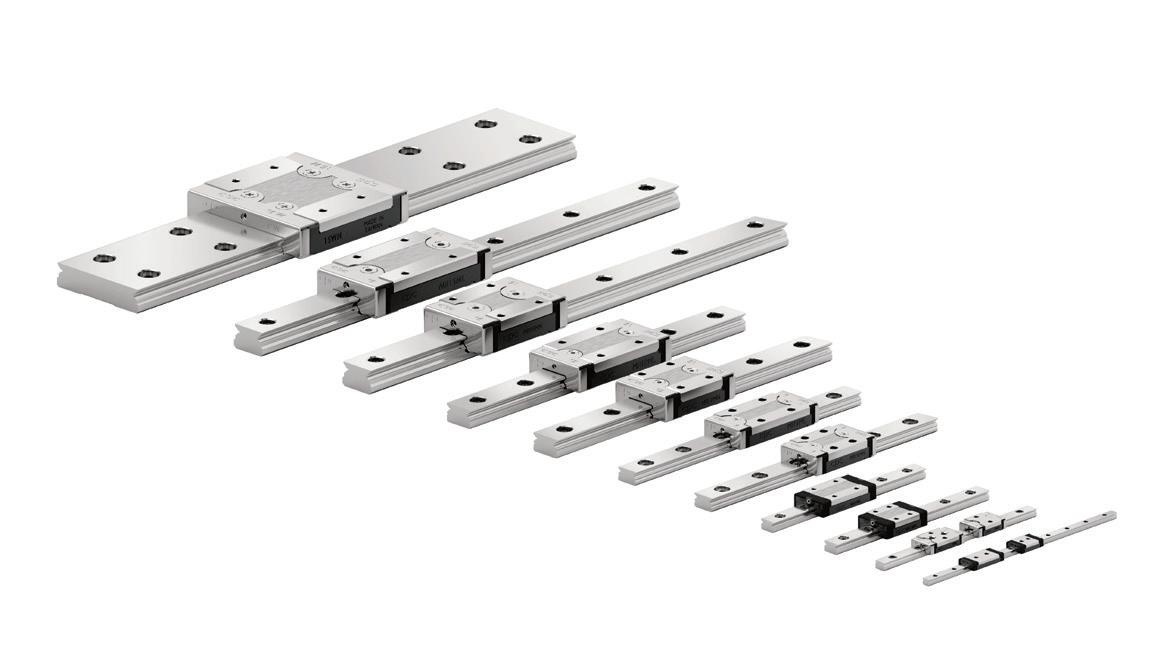
• Floating raceway wiper seal allows unrestricted self-alignment.
• Load plate ends are thinner making center a fulcrum for self-alignment.
• Our raceways are groundnot stamped - a ording precision tolerances.
• Each load plate is precision-ground and checked for consistency - unlike competitions’ stamped plates.
• Light weight components for energy reduction.
• Unibody construction for quieter operation.
www.nbcorporation.com
AEROSPACE
Enhancing precision in automated systems
Precision manufacturing is critical in the aerospace industry to ensure safety, performance, and reliability. Even the slightest deviations in components or materials can lead to significant issues, from reduced fuel efficiency to catastrophic failures.
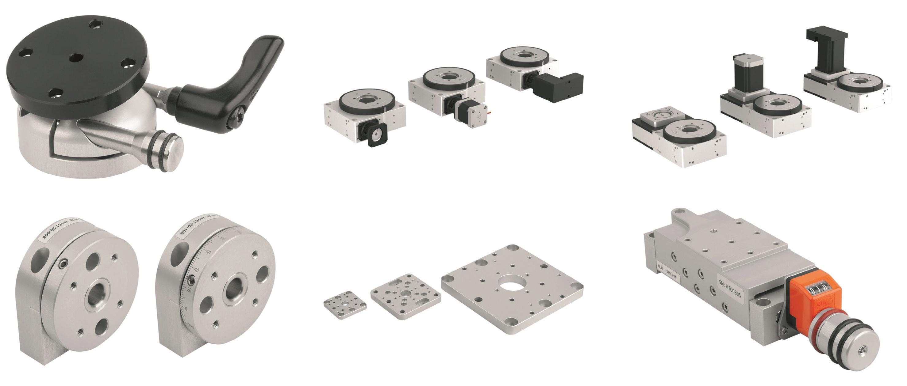
New positioning systems from norelem address evolving engineering needs, enhancing precision, reliability, and efficiency in manufacturing systems. The company launched five new families of positioning systems, including rotary tables, lifting tables, counter bearings, adapter plates, and joint heads.
The electrical positioning systems include rotary tables with an accuracy down to 0.01 mm. These are suitable for high-precision positioning of components, sensors, grippers, and stops, making them valuable components in handling systems, machine tools, and measuring equipment.
The lineup includes the High-Load Coaxial Rotary Table (21085-02), which
is driven by worm gears and can support forces of up to 12,000 N. These rotary tables feature cross-roller bearings capable of withstanding high forces and are available in three gear ratios: 20:1, 40:1, and 48:1. They can be configured with or without motors and controls. This family is joined by the Belt-Driven Rotary Table (21085-10) series, which achieves rapid, dynamic rotation with a load capacity of up to 5,000 N and a gear ratio of 2:1.
For mechanical positioning systems, norelem introduced the Counter Bearings (21161-20) product suite designed to compensate for axial and angular misalignments. These provide support for long assemblies requiring rotational positioning. They have plastic seals to protect against contamination and sliding surfaces coated with polytetrafluoroethylene (PTFE) for maintenance-free operation.
New Adapter Plates (21161-30) provide more flexibility by allowing different positioning system sizes to
connect. These products enhance compatibility, enabling users to combine compact and large positioning tables or rotary tables with varied drive mechanisms.
Furthermore, the new Lifting Tables with Mechanical Position Indicators (21141) provide a solution for height adjustments of components such as sensors, switches, and cameras. These tables feature a position indicator that displays adjustments in 0.1 mm increments, while their modular design ensures integration with other positioning components.
Lastly, norelem’s joint head family (21170) has a new variant with a quickclamping system that eliminates the need for tools, simplifies setup, and enables swift adjustments. DW
norelem • www.norelemusa.com
Design For Industry
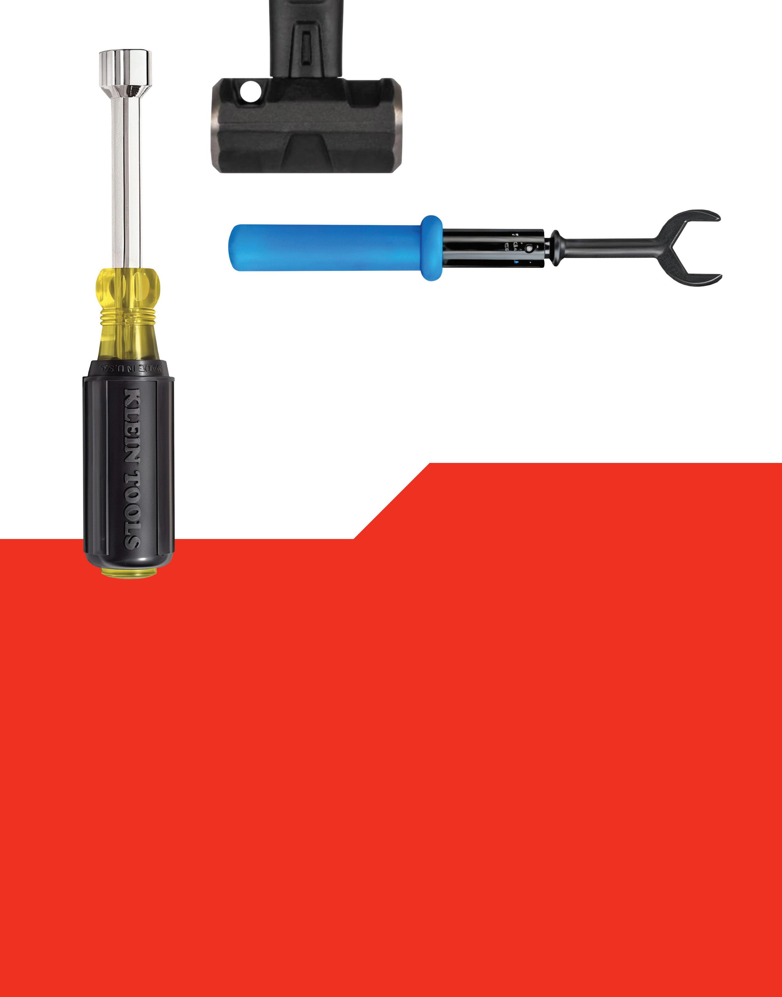
POWER TRANSMISSION RETAINING DEVICES & maintenance & assembly tools
Direct drive eliminates backlash
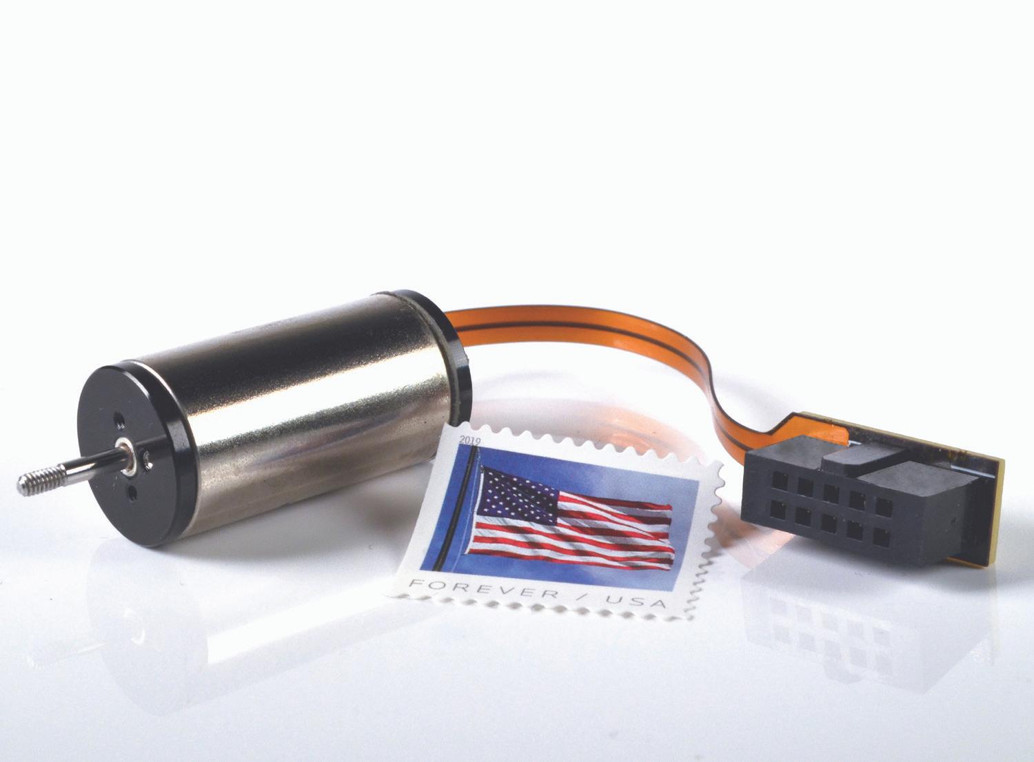
Medical devices often rely on direct-drive linear motors to avoid backlash and improve position accuracy and speed. Moticont introduced the new SDLM-016-032-0101-M (Metric) direct-drive linear motor with an integrated encoder and temperature sensor to its SDLM Series of Metric and Imperial dimensioned high-precision linear actuators. Also known as an electric cylinder, this motor is the smallest in the series, measuring 0.625-in. (15.9 mm) in diameter and 1.25-in. (31.8 mm) in length. Protected inside the motor housing, a 1.25-micron resolution linear quadrature encoder directly connected to the shaft provides accuracy with zero backlash. Additionally, monitoring the temperature from the internal temperature sensor optimizes throughput.
The new direct-drive linear motor has a stroke length of 0.250-in. (6.35 mm), a continuous force rating of 4.1 oz (1.14 N), a peak force of 13.0 oz (3.61 N), and a force constant of 3.9 oz/A (1.08 N/A). This non-commutated, low-inertia, direct-drive servo motor has quiet, long-life plain linear bearings. Connections are made via a flex cable terminated in a 10-pin female connector.
Direct coupling of the load or stage to the non-rotating shaft eliminates backlash and allows for smooth motion. Both actuator ends have M1.6X0.35, 0.10 deep threaded mounting holes to integrate into new and existing applications. Each end of the 0.07-in. (2 mm) diameter shaft has M2X0.4 male threads with a length of 0.13-in. (3.2 mm). The actuator is also available with a matching servo controller.
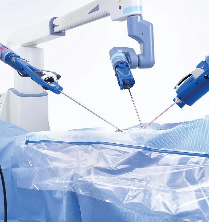
These miniature linear servo motors are suitable for medical devices, such as infusion pumps, prosthetic devices, and surgical robots. They can also be used in automotive, consumer products, aerospace, robotics, industrial automation, and laboratory applications. DW
Moticont • www.moticont.com
WHITTET-HIGGINS manufactures quality oriented, stocks abundantly and delivers quickly the best quality and largest array of adjustable, heavy thrust bearing, and torque load carrying retaining devices for bearing, power transmission and other industrial assemblies; and specialized tools for their careful assembly.
Visit our website–whittet-higgins.com–to peruse the many possibilities to improve your assemblies. Much technical detail delineated as well as 2D and 3D CAD models for engineering assistance. Call your local or a good distributor.
BEARLOK
Reducing risk in lithium-ion battery applications
In light of the ongoing energy transition, on-road vehicles and heavyduty equipment increasingly depend on lithium-ion batteries. While these batteries play a crucial role in powering the future, they are not without risks, particularly when exposed to thermal, electrical, or mechanical stresses, including manufacturing defects. Fires in lithium-ion batteries are primarily caused by thermal runaway, a process in which the battery’s temperature increases in a selfaccelerating cycle, ultimately leading to fires and explosions. This can occur due to overcharging or internal short circuits, where the separator melts, causing initial heat generation. As
the temperature rises, the electrolyte vaporizes, releasing hazardous vapors. Without countermeasures, the degrading battery enters the thermal runaway phase, resulting in catastrophic fires or explosions.
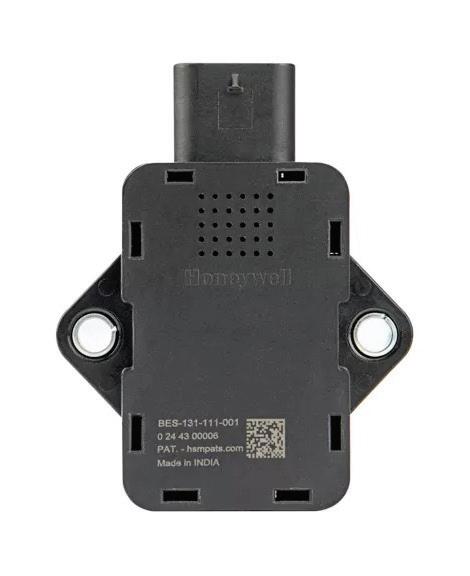
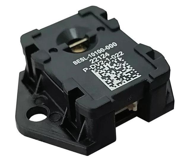
Honeywell recently released its next generation of battery safety sensors to improve safety in lithium-ion applications. The Battery Safety Electrolyte Sensor (BES) is designed specifically for onroad applications, and the Battery Safety Electrolyte Detector (BES LITE) is designed for sealed portable lithiumion battery packs in non-automotive applications.
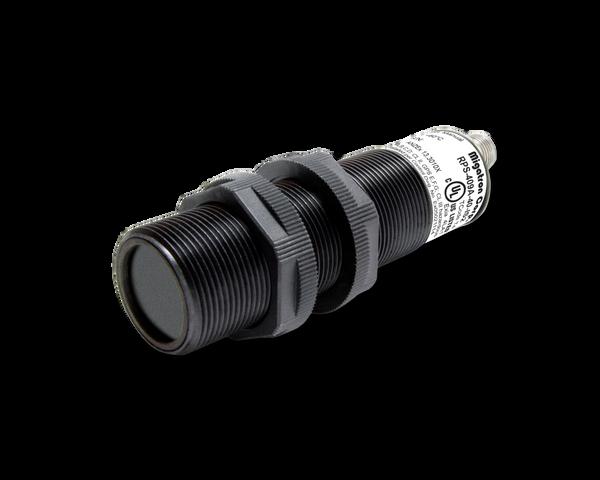
INTRINSICALLY SAFE ULTRASONIC SENSORS
The BES uses Honeywell’s proprietary Li-ion Tamer electrolyte gas detection technology to identify “first vent” events. These events serve as early warning signs of potential battery malfunctions, enabling the system to issue alerts five to 20 minutes before a fire risk. Such early detection is vital for ensuring vehicle safety and the well-being of passengers and drivers
alike. They also detect multiple gases released during thermal runaway, which minimizes the risk of false negatives. A rate-of-change algorithm facilitates its uncomplicated integration process, eliminating the need for meticulous target gas threshold testing.
BES LITE addresses needs in other non-automotive sectors and applications, such as battery energy storage systems (BESS), urban air mobility (UAM), uncrewed aerial vehicles (UAV), electric two-wheelers, three-wheelers, and portable battery applications. This low-profile and lightweight sensor uses Honeywell’s proprietary gas sensing technology. It is highly resistant to siloxane poisoning and selectively responds to only battery electrolyte vapors. This enables asset protection by providing early and reliable detection of battery electrolyte vapors without false alarms, making it suitable for critical applications and environments. It also allows compliance with international regulations and guidance by providing a deterministic detection of thermal runaway events. DW Honeywell www.automation.honeywell.com
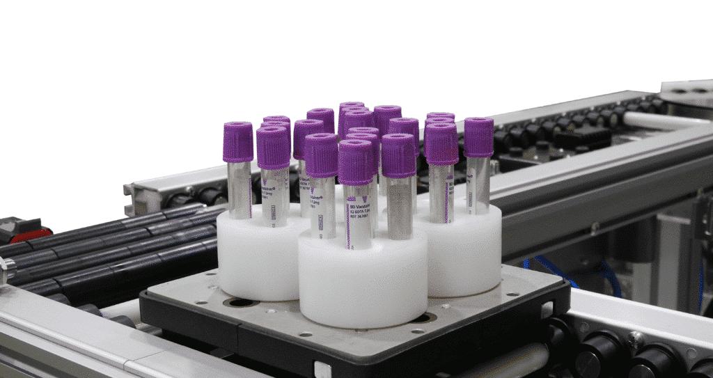
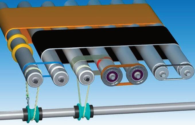
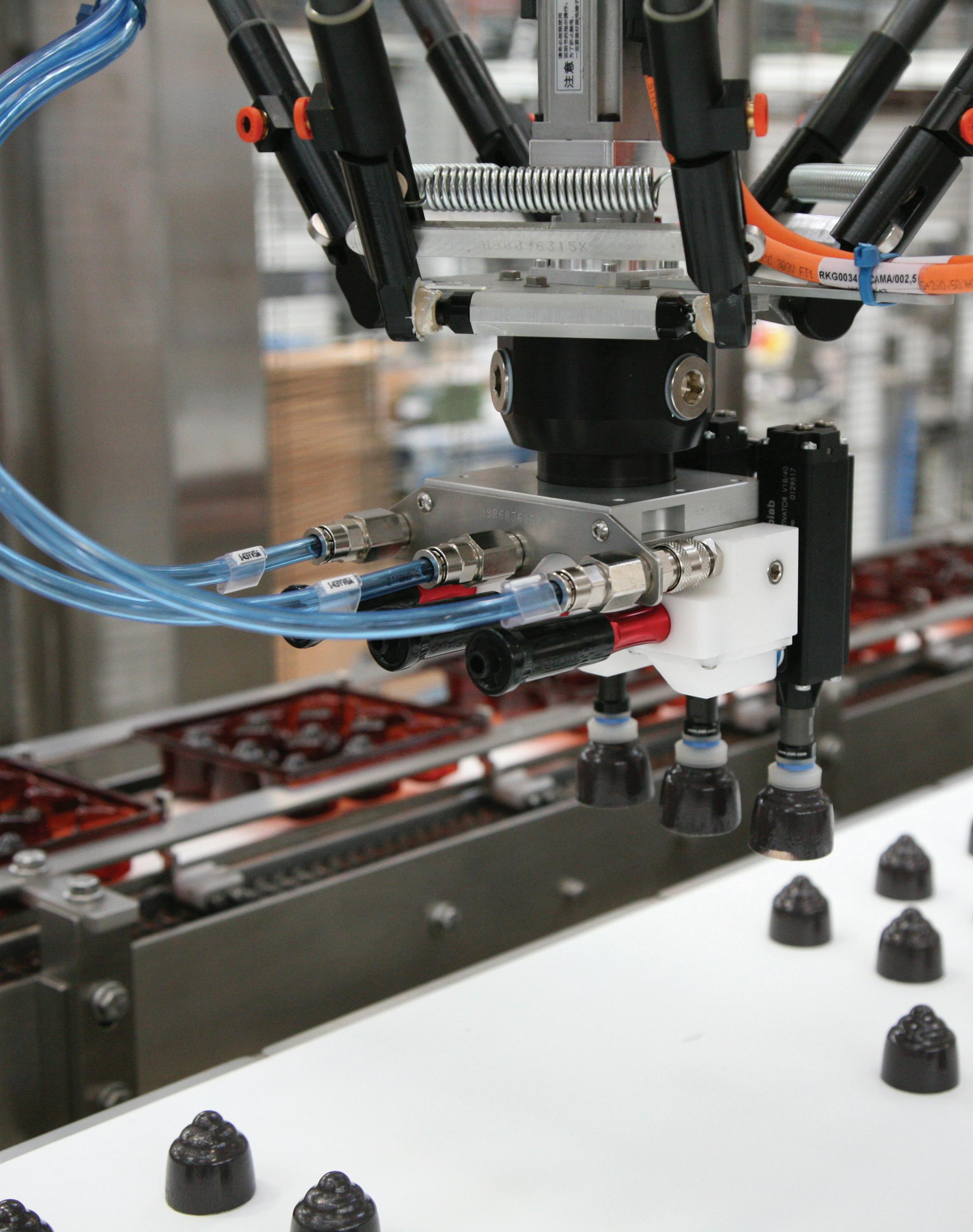
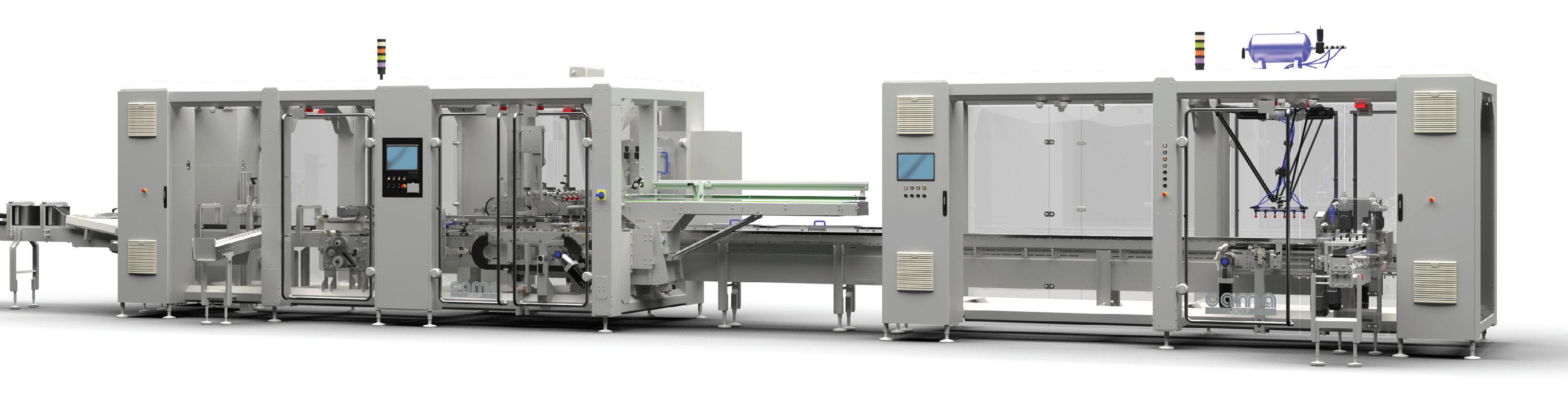
Comparing standard and pallet conveyors
Most manufacturing systems use both standard and pallet conveyors at different stages, each serving distinct purposes. Understanding their differences helps optimize their functionality.
The key distinction lies in item placement. Standard conveyors transport products directly on a moving belt, while pallet conveyors use elevated platforms that provide better control. Pallet conveyors are common in assembly processes, while standard conveyors handle secondary packaging and end-of-line functions.
Pallet conveyors offer greater precision in product placement, which is crucial for automation and humanoperated assembly tasks. They allow for exact positioning, enabling robotic arms to function accurately. Even with human workers, consistent product orientation improves efficiency, especially in complex assembly processes. Unlike standard conveyors, where products move continuously like trains, pallet conveyors function more like railcars, with each unit moving independently. This allows for flexible routing, automatic step-skipping, and easy isolation of malfunctioning units without halting the entire line.
Another advantage of pallet conveyors is their ability to prevent accumulation pressure. Standard
conveyors can cause bottlenecks where products build up and press against each other, potentially causing damage. Pallet conveyors allow individual units to stop at any point, spacing out items to avoid excessive force. Even if accumulation occurs, the pallets, not the products, absorb the pressure. Standard conveyors address this issue with accumulation tables, which help regulate product flow when necessary.
Despite their limitations in detailed assembly, standard conveyors play a crucial role in many operations. Once individual components are assembled, products move to batch functions such as sorting and packaging, where continuous movement ensures efficiency. Some industries rely entirely on standard conveyors since their processes are simple, fully automated, and involve durable products. Palletizing each item separately in such cases would slow production and take up excessive space.
The conveyor choice depends on the manufacturing process, expected output, and regulatory requirements. Conveyor systems should be viewed as interconnected components rather than standalone machines. The best solutions integrate both types to create an efficient, rhythmic material handling process tailored to specific production needs. DW
Dorner • www.dornerconveyors.com
Interpower North American and international cords allow customers to safely connect to their mains powers no matter what country they live in. Interpower cord sets provide the correct amperages and voltages, so no reconfiguration is needed out of the box. And, if the cords, cord sets, and components are in stock, they will ship the same day.
Interpower tests their cords after each stage of manufacturing. Besides 1-week U.S. lead times, and same-day shipping on in-stock products, cords can be purchased and shipped with no minimum orders.
Toll-Free Phone: (800) 662-2290
E-mail: info@interpower.com
Business Hours: 7 a.m.–5 p.m.
• EDITED BY MIKE SANTORA
The next step for the industrial metaverse
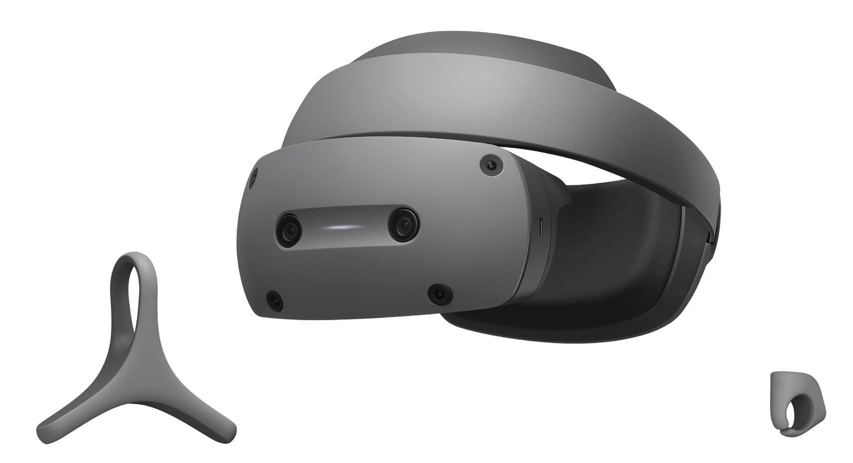
Siemens Digital Industries
Software, in collaboration with Sony Corporation, has announced that it is delivering on its next-generation immersive engineering roadmap that brings together Siemens’ NX software for product engineering with Sony’s headmounted display (HMD) to enable the industrial metaverse.
The XR HMD (SRH-S1) features Sony’s high-definition 1.3-type OLED Microdisplays with 4K resolution, and its proprietary rendering technology enables real-time, high-definition, and realistic rendering of 3D objects. It also has a pair of controllers optimized for intuitive interaction with 3D objects and precise pointing. The head-mounted display is also optimized for extended
creative use, designed with comfort and stability in mind.
“We embarked on this collaborative project with Sony to deliver the power of the industrial metaverse to our community of designers, engineers, and manufacturers directly in our flagship product engineering software,” said Bob
Haubrock, senior vice president, Product Engineering Software, Siemens Digital Industries Software. “After previewing the HMD at CES last year, our collective teams have built a set of tools that revolutionize how mixed reality is used in the engineering space — to not only support global collaboration based on
high-fidelity 3D models, but to enable cocreation directly on vital 3D CAD data in a managed, secure environment. Today, we are making this next generation set of technologies available to our customers.”
“Since announcing our collaboration with Siemens at CES 2024, we’ve had opportunities to get direct feedback from Siemens’ customers about the technology, and as Siemens’ NX users ourselves, we were excited that many of them share our enthusiasm for the potential of Immersive Engineering,” said Seiya Amatatsu, Incubation Center, XR Technology Development Division, Sony Corporation.
“Siemens’ Immersive Engineering technology helps our designers and engineers see, design, and edit parts more easily with the unique controllers, enable our customers to experience their car at human-scale before it is built, and help stakeholders from production easily collaborate with designers and engineers to validate parts before manufacturing,” said Ian Briggs, Founder and Head of Design, Briggs Automotive Company (BAC).
Siemens’ Immersive Engineering toolset brings mixed reality to the product engineering and manufacturing community, enabling high-fidelity
Interpower North American and international cords and cord sets provide the correct AC power for each country-specific customer as to safely connect to each country’s mains power. Interpower tests and inspects their cords after each stage of manufacturing.
®
® With Interpower® cords and cord sets, you don’t have to wait weeks on North American and international cords. With over 2 million cords and components currently in stock to ship the same day, and 1-week U.S. lead times on customized country-specific power cords, you can ease into the new year without stressing about power cords.
Toll-Free Phone: (800) 662-2290
E-mail: info@interpower.com
Business Hours: 7 a.m.–5 p.m. CST
Order Online! www.interpower.com
The XR HMD (SRH-S1) features Sony’s high-definition, 1.3-type OLED Microdisplays with 4K resolution. Its proprietary rendering technology enables real-time, high-definition and realistic rendering of 3D objects.
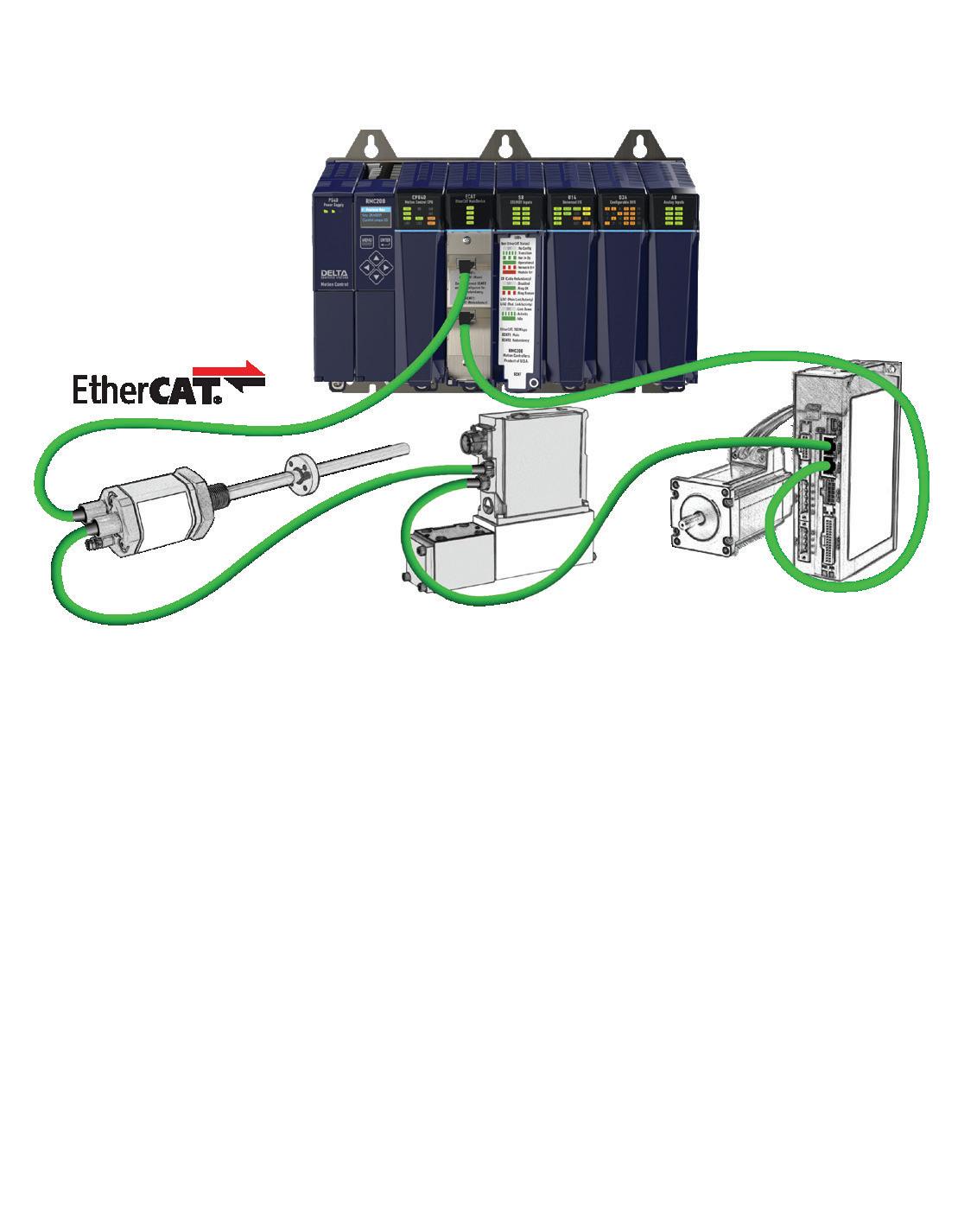
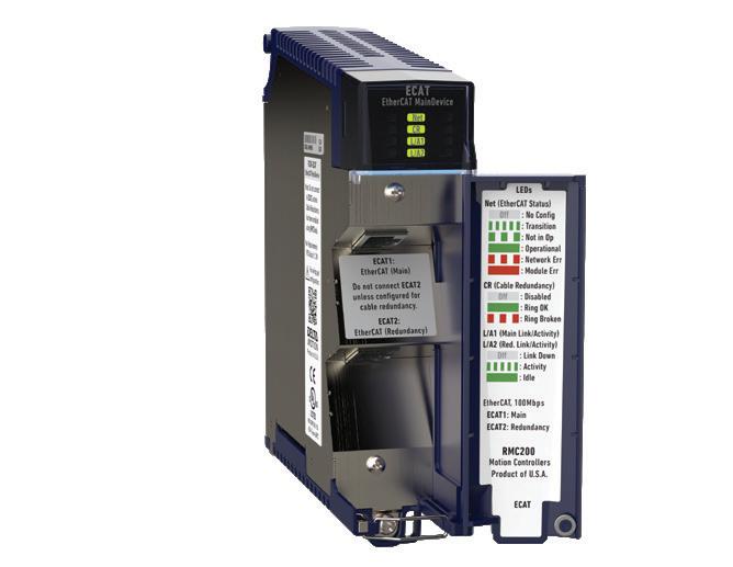
Drive Forward with EtherCAT from Delta Motion
mixed reality and 3D-focused collaboration. The Immersive Engineering solutions include:
NX Immersive Explorer: A headset-agnostic solution that designers and engineers use to conduct informal design reviews and collaborate using 3D CAD data derived from Siemens’ NX software for product engineering.
NX Immersive Designer: Designed from the ground up to take advantage of the capabilities of Sony’s HMD and creative controllers, NX Immersive Designer enables designers and engineers to interact, manipulate, and collaborate around graphically rich 3D product models natively in NX, without the need for additional preparation or software. Using Sony’s Ring and Pointer controllers for object interaction and precise 3D geometry manipulation, designers and engineers can interact directly with product prototypes, NX commands, and menus.
NX Immersive Designer supports augmented, mixed reality environments to place virtual objects in the real world, conduct design sessions in a high-fidelity virtual design review space, or through large scale, high-resolution virtual monitors. For even more efficient interaction, users can take advantage of NX Voice Command Assistant in the immersive environment to navigate multiple levels of menus and clicks with simple, easy-to-use spoken keywords.
NX Immersive Collaborator: NX Immersive Collaborator builds on the capabilities of NX Immersive Explorer and Designer to allow organizations of all sizes to take advantage of both co-located and remote design review with multiple participants. NX Immersive Collaborator requires Siemens’ cloud-enabled NX X to host design collaboration and review sessions — participants can join using local VR or desktop view for broad collaboration options. Value-based licensing tokens are used for only hosting sessions, with participants able to join remotely for free.
NX Immersive Designer is available for all NX customers with the latest updates and through Siemens’ value-based licensing. NX Immersive Collaborator will be available later this month with the NX X update and through value-based licensing. The NX Immersive Engineering tools have been developed to exclusively work with Sony’s HMD offering that include 4K OLED Microdisplays and dedicated controllers. The HMD with the controllers is needed for both NX Immersive Designer and Collaborator. DW
Siemens • siemens.com
• EDITED BY MIKE SANTORA
FAA prepares to take flight with new CAD software
The U.S. Federal Aviation Administration’s (FAA) mission is to provide the safest, most efficient aerospace system in the world. The FAA is headquartered in Washington, D.C. and maintains nine regional offices, Air Route Traffic Control Centers, and Terminal Radar Approach Control Facilities across the nation, as well as other key facilities. In addition, the FAA maintains a presence in every major and regional airport in the United States and has several international offices around the globe.
Within the FAA, the Computer Aided Engineering Graphics (CAEG) Program is responsible for supporting Engineering Services with their understanding and expertise of engineering technology.
Engineering Services consists of over 1,300 engineers, designers, and drafters who develop and maintain the FAA infrastructure.
The Challenge
Historically, the FAA used MicroStation to create CAD drawings. As part of an IT modernization initiative, the organization decided to migrate to Autodesk AutoCAD, while remaining on their existing ProjectWise data management system. An integral stage in this process was how the CAEG Program team could train and support all 1,300 users.
In addition to learning the basics of AutoCAD, all users also needed to understand how to use AutoCAD with the FAA-specific workflows and with the
agency’s ProjectWise data management storage system. Since these workflows are unique to the FAA, there was no “off-the-shelf” training program available for use.
The Solution
Over the years, the CAEG Program Manager worked on several projects with IMAGINiT, who then introduced CAEG’s Program leaders to their sister division, ASCENT, known for its courseware development and technical writing capabilities. The CAEG team decided to move forward and teamed up with both ASCENT to develop a custom integrated AutoCAD with ProjectWise training initiative, and with IMAGINiT experts to provide Autodesk software training.
After the initial in-person classes, CAEG leadership decided to direct users to online, self-paced learning using the IMAGINiT ProductivityNOW learning management system provided. Here, we see an example of the online learning interface.
Design Notes
• The CAEG team assembled a working group of 10 to 15 people who had either worked to develop FAA’s workflows and procedures, were CAD Administrators, or were leaders with an excellent understanding of the requirements from Engineering Services. This group collaborated with the ASCENT team who facilitated instructional design analysis sessions to discuss the required learning objectives.
• Using the information gathered from these sessions, and applying their own industry and instructional design experience, ASCENT identified the learning objectives and the knowledge transfer required for FAA staff to work competently with AutoCAD and the ProjectWise data management system. ASCENT was then able to create the required learning guide.
• Eight IMAGINiT education specialists used the FAA’s newly created custom learning guide to train 1,300 employees over a twelve-month period.
The Results
During the content development phase, ASCENT used a collaborative design process, obtaining feedback from the CAEG team throughout the project to make decisions. ASCENT delivered a custom learning guide for the FAA with relevant instructional content and detailed hands-on practice exercises and corresponding instructor tools and supplemental videos for enhanced learning.
The training from IMAGINiT went smoothly and provided attendees with the knowledge they required to work with AutoCAD and ProjectWise in the FAA’s engineering environment.
While in-person classes are more cost effective when run at full capacity, with new employees continually being hired and onboarded, the FAA team recognized that it wasn’t feasible for them to wait until a full class could be scheduled. After the initial inperson classes, CAEG leadership decided to direct users to online, self-paced learning using the IMAGINiT ProductivityNOW learning management system provided. Relevant content from the learning guide was imported into ProductivityNOW in addition to videos of presentations and demonstrations from IMAGINiT instructors.
One obstacle that arose during training was that learners were required to access an FAA production training database which needed to be granted and then reset following each training event. To overcome this challenge, ASCENT eliminated the need to access a production training database by developing simulations for each hands-on practice. Learners were able to practice each task in a simulated software environment that had the same look and feel as the live environment. This online training delivery format with simulation-based exercises has saved significant time and money for the FAA.
The FAA online training program is now an integral part of the onboarding process for new employees. In fact, new hires can’t access the ProjectWise data management system until they have completed the training. The training content is always available through the online ProductivityNOW platform which employees have access to whenever and wherever they need it.
Looking ahead, the FAA anticipates working again with ASCENT to update the course as new software and workflows are implemented, and with IMAGINiT to assist with additional training requirements. DW
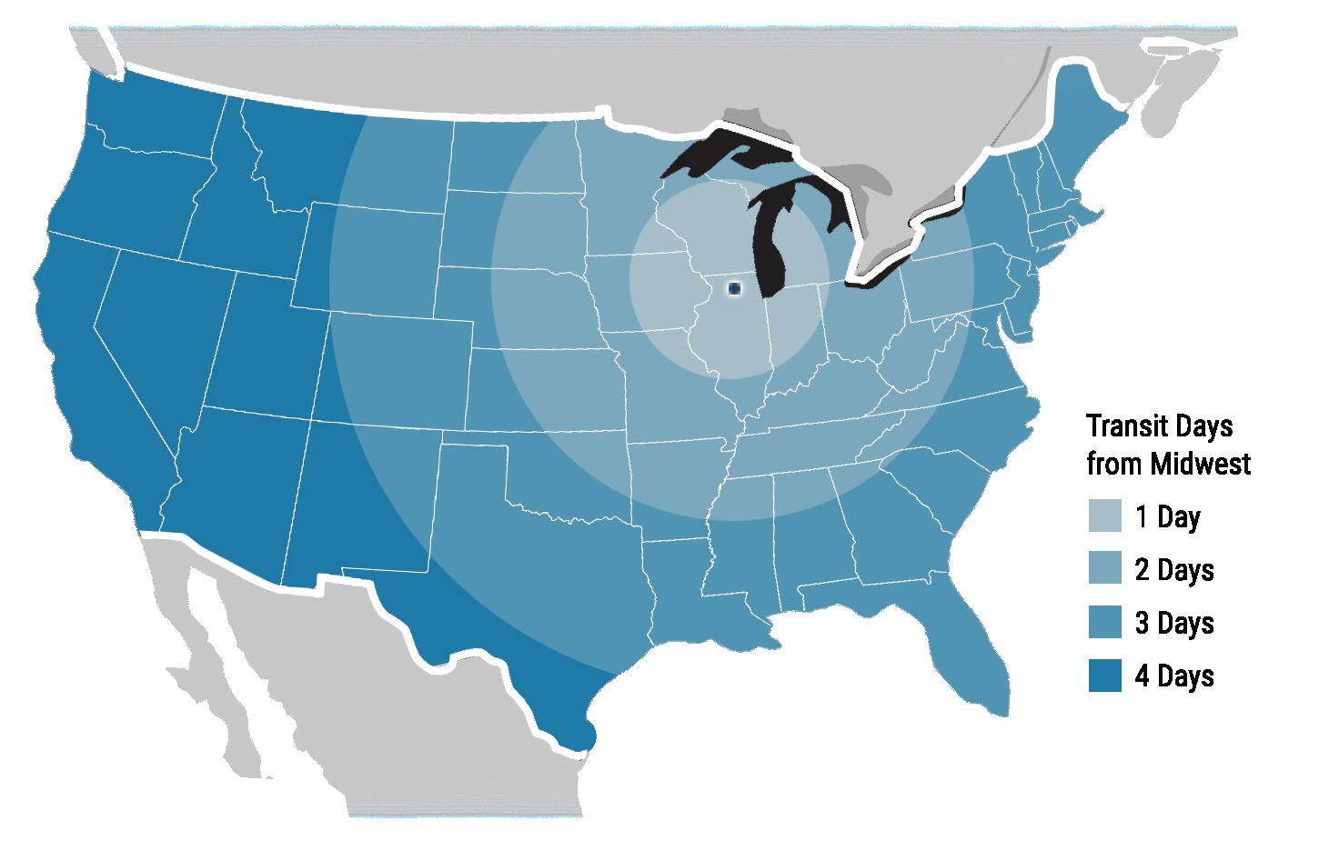
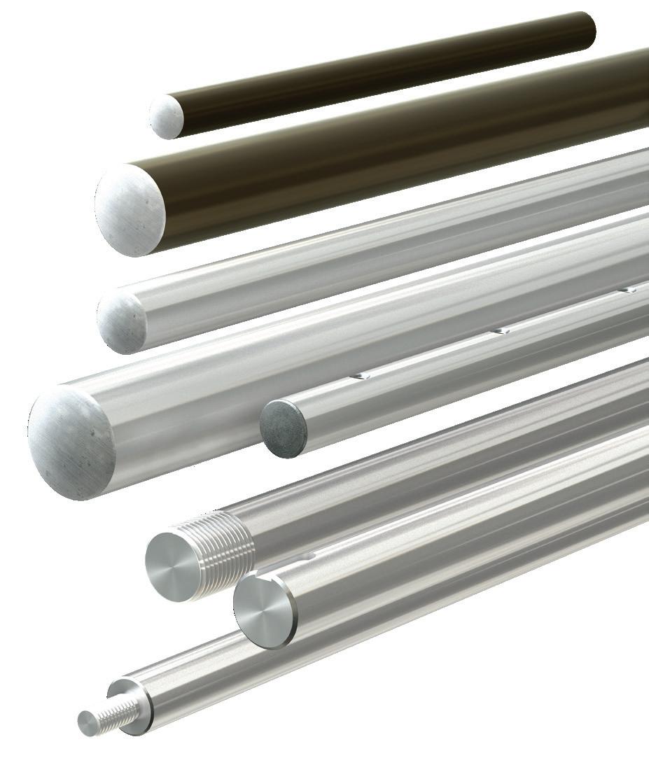
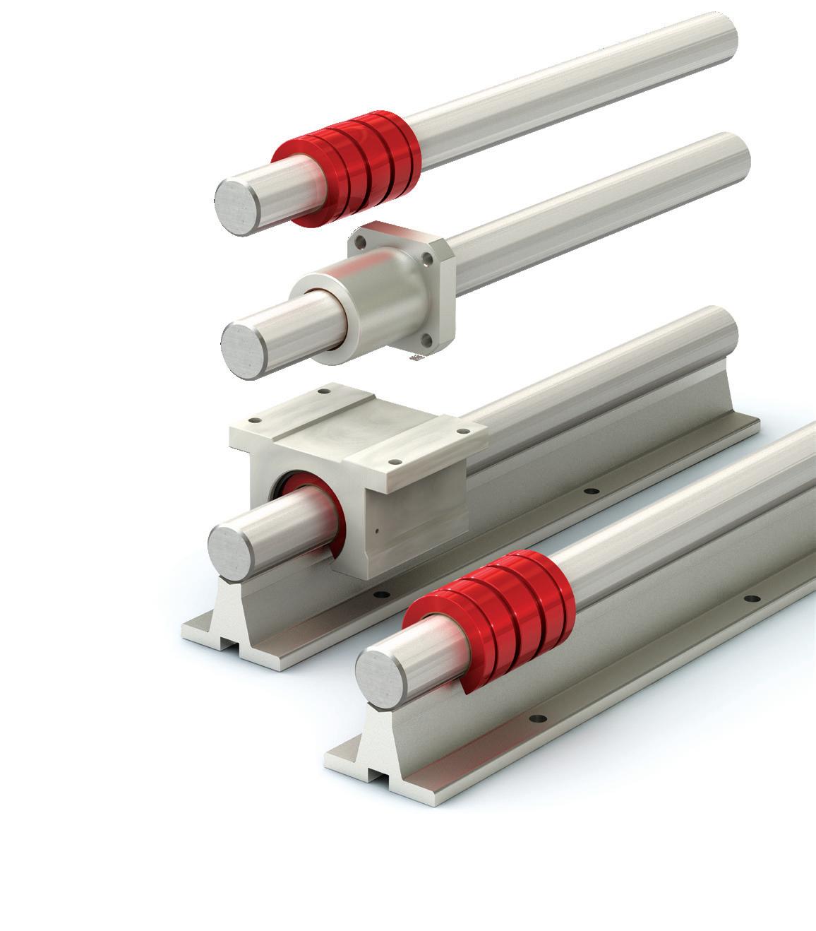
Don’t Get Shafted by Supply Chain Issues
Get Quality, American Made Shafting within Days, NOT Weeks!
PBC Linear supplies American-made cut-to-length steel, stainless steel, and aluminum shafting with various available machined end options. Their modernized manufacturing facility is set up to keep shafting products in-stock, while their Midwestern location offers quicker and cheaper shipping, avoiding the uncertainty of border customs.
Additionally, matching your bearings and shafting is critical to maximizing system performance. PBC Linear shafting is engineered and manufactured to work specifically with Simplicity® plain bearings for optimal performance. All ready now to ship to your door.
• EDITED BY MIKE SANTORA
No small potatoes for this lowfriction bushings application
A leader in agricultural machinery innovation planted 1,500 acres of potatoes at Warden Hutterian Bretheren in Washington using its cutting-edge 12-row potato planter fitted with Vesconite bushings. This is an important accomplishment in the company's pursuit of advancing agricultural technology.
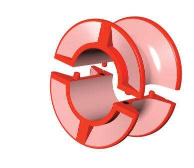
The new planter is equipped with Vesconite low-friction bushings in critical areas such as the parallel arms of the row units, pivot points of the hitch, depth wheel linkage, toolbar knuckle, and folding slider. Vesconite was chosen because of its low friction, high strength, minimal maintenance, extended service life, superior durability, and to ensure smooth operation.
"The Vesconite bushings proved to
the OEM manufacturer’s mechanical design engineer.
“Some of the bushings were exposed to very high loads and extreme dust, yet they performed admirably with no visible wear.”
One of the standout features of the new planter is its remarkable precision. Operating at 5.2 mph (8.3 km/hour), the planter ensures accurate placement with virtually no misses and minimal doubles, making it a game-changer in potato farming.
Building on this success, the manufacturer plans to expand its production of the new planter model.
"Now that we have a proven concept, we are excited to move forward with our plans,” said the design engineer.
“Our goal is to expand our production capabilities and start building more machines in the coming years," he added, noting that the company has set its sights on eventually selling these advanced machines globally.
With potatoes ranking as the third most important crop in terms of global food consumption after rice and wheat, the latest technology in potato planting is crucial for enhancing efficiency, using resources effectively, and minimizing waste.
The OEM agricultural equipment maker’s planter promises to assist in boosting potato yields and making potato planting more precise and profitable. DW
Vesconite • www.vesconite.com
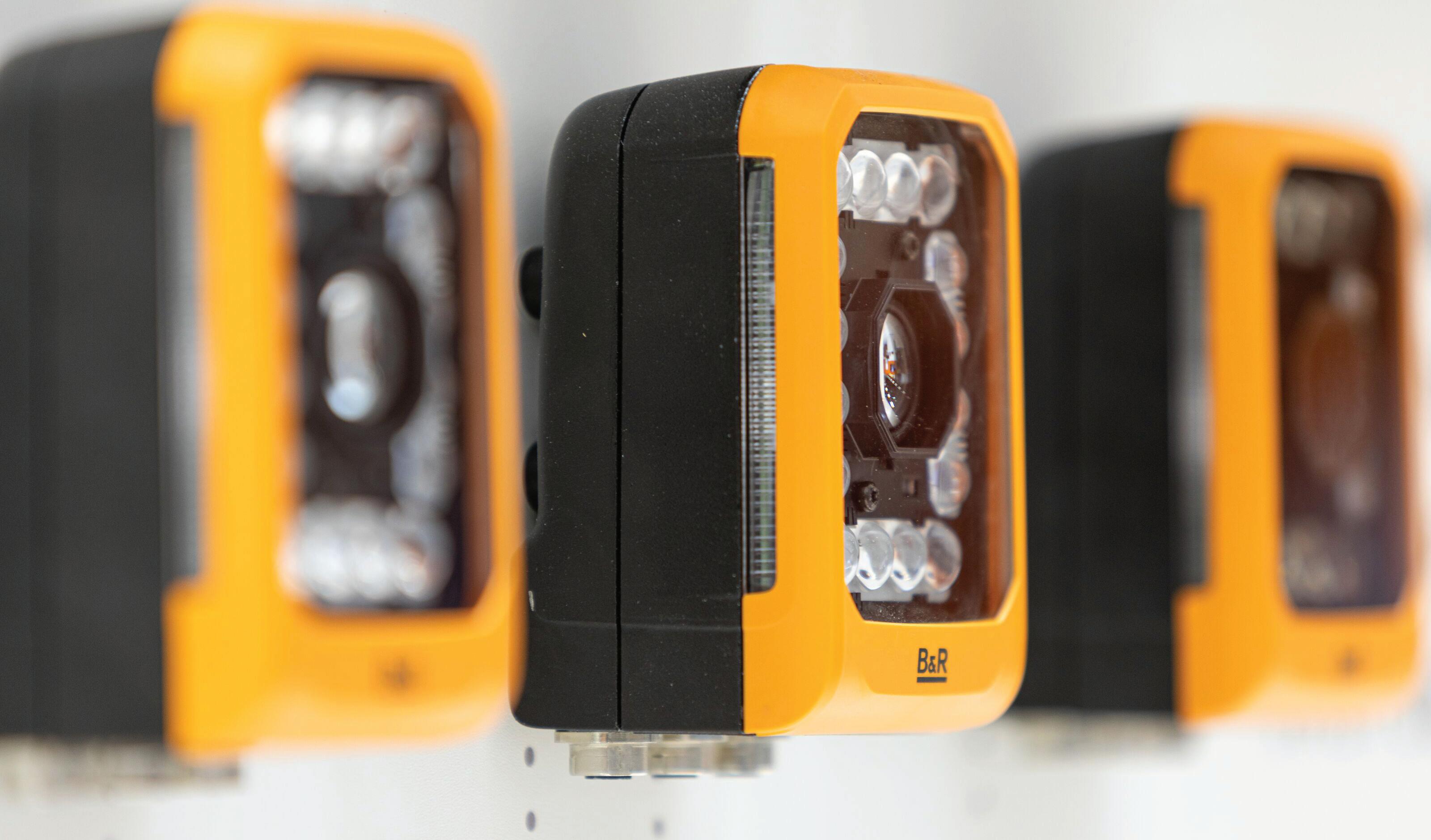
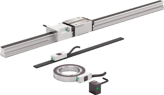
Expand your field of vision with B&R Vision Systems
B&R is expanding the field of vision with a complete portfolio of cameras, lenses, lighting and software – all fully integrated in the B&R ecosystem. With groundbreaking performance and scalability, B&R machine vision gives machines unprecedented new capabilities.
• CONTRIBUTED BY DEL WILLIAMS
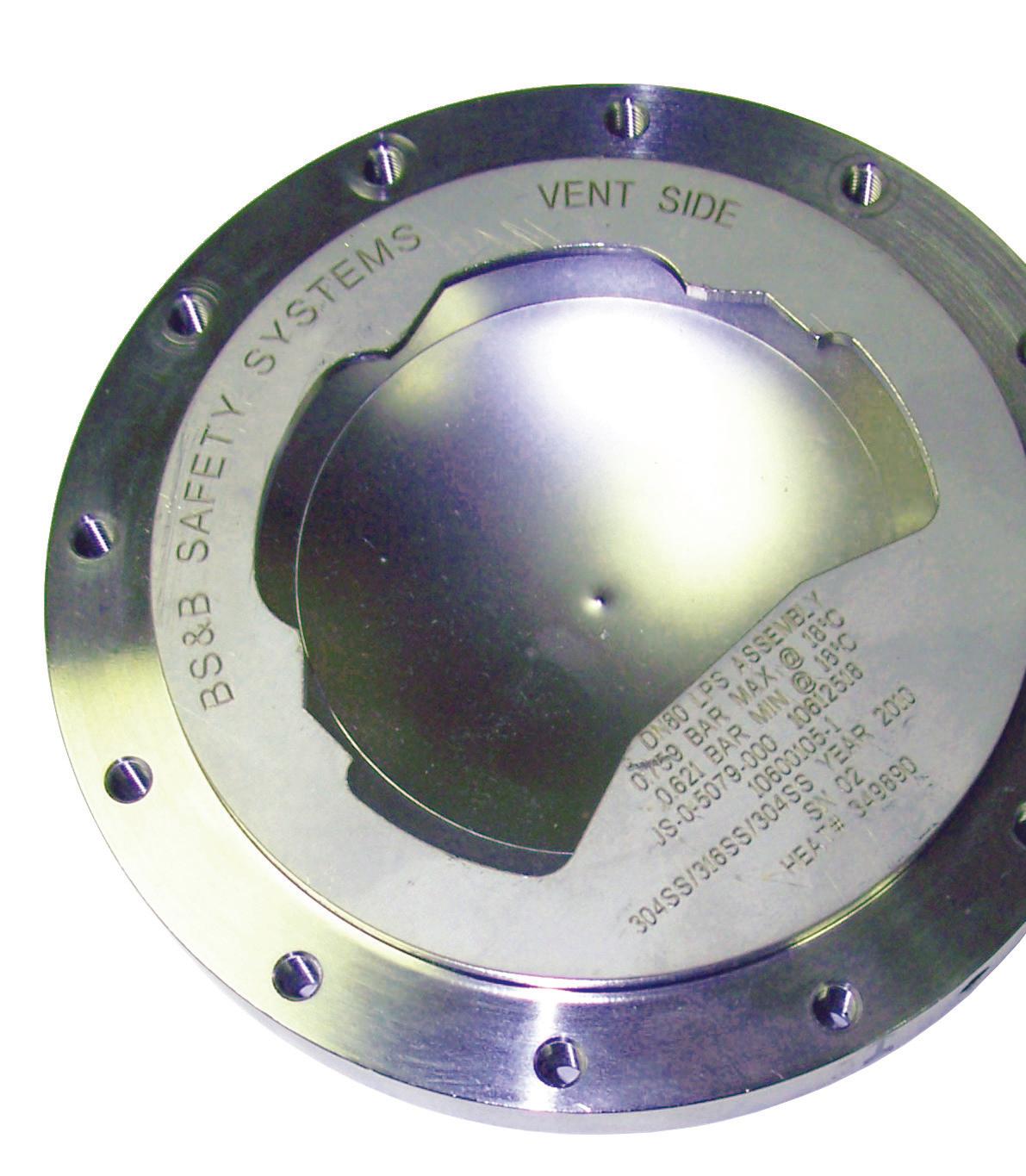
Speeding up custom aerospace rupture disk prototypes
Like a well-coordinated pit crew, this rupture disk manufacturer has streamlined the custom prototype process to accelerate the service to aerospace OEMs.
Taking its cue from racing car pit crews, the fast-tracked development process involves the coordination of specialized internal teams with unique skillsets to ensure timely delivery of dependable prototypes.
KOTOIMAGES • shutterstock.com
Aerospace OEMs rely on rupture disks for pressure relief and pressure release of gases and liquids in applications ranging from compressed gas cylinders to propulsion systems, aircraft wheels, fuel storage systems, and environmental/ fire protection equipment. However, the challenge of time faces all aerospace product designers: how do we get a custom solution in an acceptable timeframe?
Now, at least one industry innovator has streamlined the prototype process to expedite the delivery of customized solutions that meet a wide range of unique application requirements. Taking its cue from racing car pit crews, the fasttracked development process involves the coordination of specialized internal teams with unique skillsets to ensure timely delivery of dependable prototypes
that are prepared for evaluation, additional adjustments, or full-scale production.
Global demand for new rupture disk designs
With the global energy pivot that is occurring combined with stronger sustainability strategies, the 2020’s mark an aggressive period of innovation that impacts the aerospace industry. The pace of creativity is faster than ever with OEM product development cycles compressed to achieve the fastest entry to market.
“OEMs often require a unique rupture disk in terms of its dimensions, material combinations, or the operating conditions. In many cases, the rupture disk is a last-minute consideration once other design parameters are defined and so they need a custom prototype
delivered within relatively tight timelines as part of their product development,” said Geof Brazier, Managing Director, BS&B Safety Systems, Custom Engineered Products Division.
Aerospace OEMs increasingly require expedited delivery of prototypes without compromising on quality or performance. Recognizing the need, BS&B Safety Systems developed a comprehensive support program called the Prototype Introduction Team (PIT) for OEMs that require a “white glove” experience for custom rupture disk device.
According to Brazier, the program was developed and patterned after the race car pit crew strategy, where highly trained individuals quickly and seamlessly work together — each with a specific role in the process and with a high degree of anticipation of the customers’
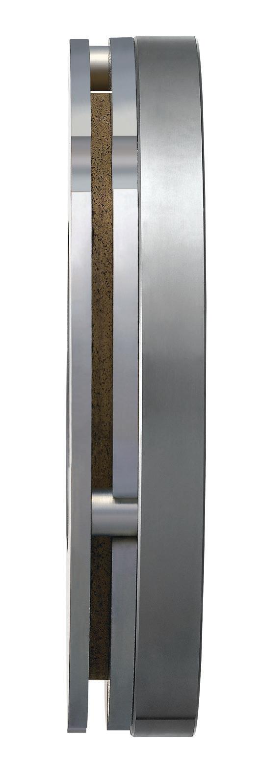
The expedited custom prototype program for aerospace results in high quality rupture disks that quickly progress from concept to production level performance.
requirements. The PIT crew’s individual responsibilities are fine-tuned for maximum efficiency, in coordination with the other members of the crew since every step can be critical to winning.
Achieving such rapid turnarounds requires meticulous planning, rigorous training, and exceptional teamwork. At BS&B, the PIT team involves experts assembled from sales, engineering, purchasing, manufacturing, and quality control. The PIT team incorporates design engineering throughout and manages all aspects of scheduling to ensure quality, performance, and aesthetic condition with on-time completion and delivery.
According to Brazier, the PIT program’s coordination and attention to detail has accelerated product development of custom rupture disks and accelerated OEM design decision making.
According to Brazier, the PIT Program design team’s expertise extends from rupture disks and buckling pin valve technology to explosion protection and prevention devices. The custom engineered products team has decades of machining experience, which now embraces 3-D printing capabilities to reduce the time required for prototype manufacture.
Various considerations available to the OEM include novel product marking, inclusion of integral flame arresters or Burst Alert sensors, and cleaning, custom packaging, and certifications. Extensive validation capabilities further support the OEM to achieve project targets on time and on budget.
“Every application is unique, so questions inevitably arise. To ensure the OEM can get answers at any time during prototype creation, we assign a project manager to serve as a single point of contact,” said Brazier, adding that close coordination not only reduces potential technical issues but also supports the customer who may have evolving design factors that impact the pressure relief device and may trigger a running change.
For aerospace OEMs, the expedited prototype program results in rupture disks that quickly progress from concept to production level performance, price, and quality.
“Approximately two-thirds of our prototypes progress to the next development step,” explained Brazier. “Some become another prototype. Others move quickly into full production.”
Rupture disk devices are a vital safety technology that can protect aerospace OEM equipment from potentially damaging overpressure or vacuum conditions in various processes. When customization is necessary to accommodate the OEM’s specific processes, working with an expert partner capable of expediting prototyping can dramatically improve the equipment’s reliability and longevity while reducing maintenance and overall cost of ownership. DW
Editor’s Note: Del Williams is a technical writer based in Torrance, California. BS&B Safety Systems www.bsbsystems.com
LISA EITEL • EXECUTIVE EDITOR
Encoders increasingly leverage hardware and software to allow dynamic setting changes (including those to resolution and output circuit type) as well as reporting of current conditions and predictivemaintenance data
processing capabilities encoder EXPANDING
Encoders are essential speed and position feedback components. For their operation, they use signals based on light, magnetism, or magnetostrictive material behavior. In fact, encoders are at their core sensors — transducers convert one form of energy (typically electromagnetic or mechanical) to another. Feedback devices qualify as encoders if they employ a gradated or marked (coded) wheel or tape of some type. After all, the meaning of encode is to convert some message or other information into a coded format that the receiver (in automation, a controller) can understand.
Today, encoders advancements are facilitating an array of IIoT functions. Smart-encoder implementations abound. Some come with standard connectivity ports and networking capabilities (such as USB and EtherCAT) as well as opensource software compatibility. Others come with proprietary connectors and software designed only to work with one manufacturer’s encoder. Engineers can also write software in-house as well. So, the OEM must have programmers on staff or hire them to get outsourced encoder programming. While this may seem like an option to get the besttailored application, keep in mind that
having encoder programmers on staff or hire adds expense and design time to machine builds. That’s unnecessary when off-the-shelf or manufacturer-provided software works just as well.
Consider the programming of some smart encoders. These might connect to a computer and the engineer configures the encoder through a graphical user interface (GUI) to get target settings. Then the smart encoder sends data back to the computer or other I/O system if applicable.
The ability to adjust resolution onthe-fly is especially useful because it doesn’t force OEMs and end users to
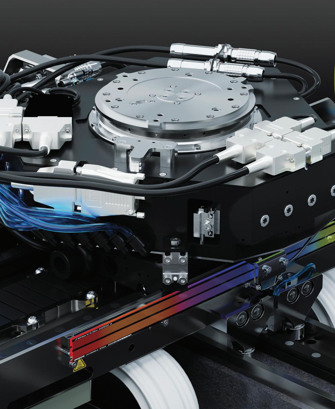
Supporting AI is semiconductor technology employing modular, powerful, and miniaturized chiplets rather than monolithic chips. In fact, contact distances have shrunk from 10 µm in 2010 to 2 µm — especially useful for use on humanoid robots and self-driving vehicles. Supporting their production are HEIDENHAIN encoders with MULTI-DOF technology that can compensate for real-world inaccuracies caused by thermal and mechanical assembly factors — and achieve position accuracies better than
1 µm. Dplus encoders with MULTI-DOF technology maintain compatibility with standard HEIDENHAIN LIP 6000 encoders ensuring accuracy regardless of mounting or environment.
The EnDat 3 interface from HEIDENHAIN imparts MULTI-DOF solutions with the ability to calculate and transmit all relevant position values over a single cable. An electronic ID label provides information about the encoder and system to enable automatic encoder setup and even automatic setup of the
larger system if the OEM implements system data storage. EnDat 3 also transmits temperature-sensor, conditionmonitoring, and predictive-maintenance data to motion or position controllers in electronics and semiconductor production systems.
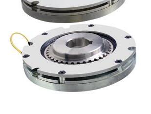
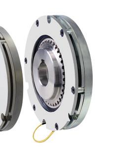
ETEL motion systems integrate HEIDENHAIN encoders, direct-drive motors, controllers, and vibration isolation for a comprehensive semiconductor-production platform.
pick resolution right away. In contrast, manufacturers set the resolution of traditional encoders when the OEM or user orders it … so resolution is set for the life of the device.
Smart encoders allow the resolution to change at any time during operation, which boosts flexibility. It also decreases costs because OEMS don’t need to buy many encoders for various resolutions — as again, one encoder can serve any number of resolutions.
Smart encoders also allow software upgrades. Both the computer software and encoder firmware are changeable by the end user. (If any faults exist in a traditional encoder, the engineer must order a replacement — causing downtime and expense.) Smart encoders can even make use of software to solve software problems or temporarily compensate for hardware difficulties. Diagnostics let engineer proactively compensate for issues as well. Continuously encoderhealth reporting minimizes downtime, as end users don’t need to wait for the encoder to break before replacing it. Instead, plant personnel can monitor it in software and order replacement parts upfront — and even perform system upgrades before critical failures occur.
Microprocessors in encoders for signal processing
Embedded microprocessors in encoders offer many advantages. They improve reliability, accuracy, and responsiveness. Signal processing software running on a microprocessor can make rotation measurements that are accurate and dynamic, but with fewer moving parts than legacy encoder setups. Plus, encoder microprocessors allow changes to measurement characteristics via software. That means users can tailor the encoder resolution, zero-point location, and direction settings without mechanical adjustments.
Embedded microprocessors make encoders work as diagnostic tools and programming, too. This can reduce the time it takes to get integrated designs to market — plus reduce machine downtime once the design is up and running.
Microprocessors on encoders also enable different approaches to system design and configuration. Rather than wiring everything to one computer, embedded encoder smarts allow system configuration via smartphones or web portals. Embedded microprocessors can also simplify the controller and drive system. Here, the embedded microprocessor performs various feedback and control operations; this can free up the drive system for other tasks.
Furthermore, as the IIoT spreads in industrial applications, encoderembedded microprocessors can provide data to system and operationslevel networks. These don’t just send data to a drive; embedded encoder microprocessors can send data to myriad
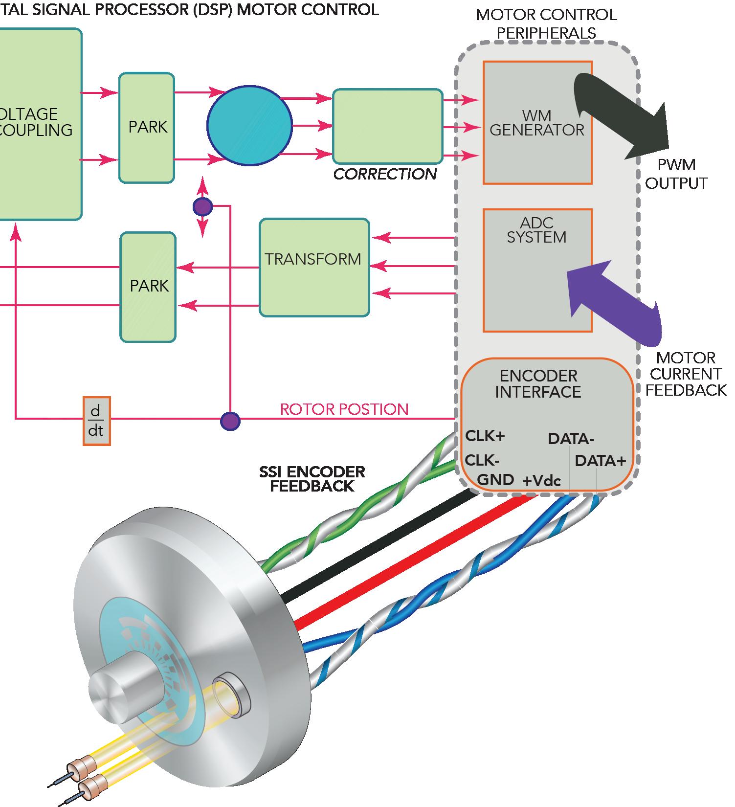
The SSI encoder interface is simple, with just four wires for communication (a twisted pair for data and a twisted pair for clock signals) and two wires for power.
components in the system and can also be checked by any other component in the system. While this creates quite a large amount of data, the embedded microprocessor allows handling it and interpreting it without burdening the host computer or drive system. This transforms encoders from single-use components to multi-function nodes in fully integrated systems.
Various encoder communications
Today’s encoders allow for the use of multiple interface options, including PROFINET (RT or IRT), CANopen, EtherCAT and EtherNet/IP. However, serial communication is a simpler solution than parallel wiring (which requires a twisted pair of wires for each bit of
output) and suitable for applications not complex enough to justify a fieldbus or Ethernet-based protocol. Consider the differences between the most common absolute encoder serial interfaces available today: SSI, BiSS, Hiperface DSL, and EnDat.
Synchronous serial interface or SSI: As its name suggests, SSI is a synchronous protocol — meaning that data goes from the encoder to the controller synchronously via a clock signal or pulse originating from the controller. The encoder output can be in binary or Gray code, and one bit is transmitted per clock pulse … with standard word lengths of 13 bits for single-turn encoders and 25 bits for multiturn encoders.
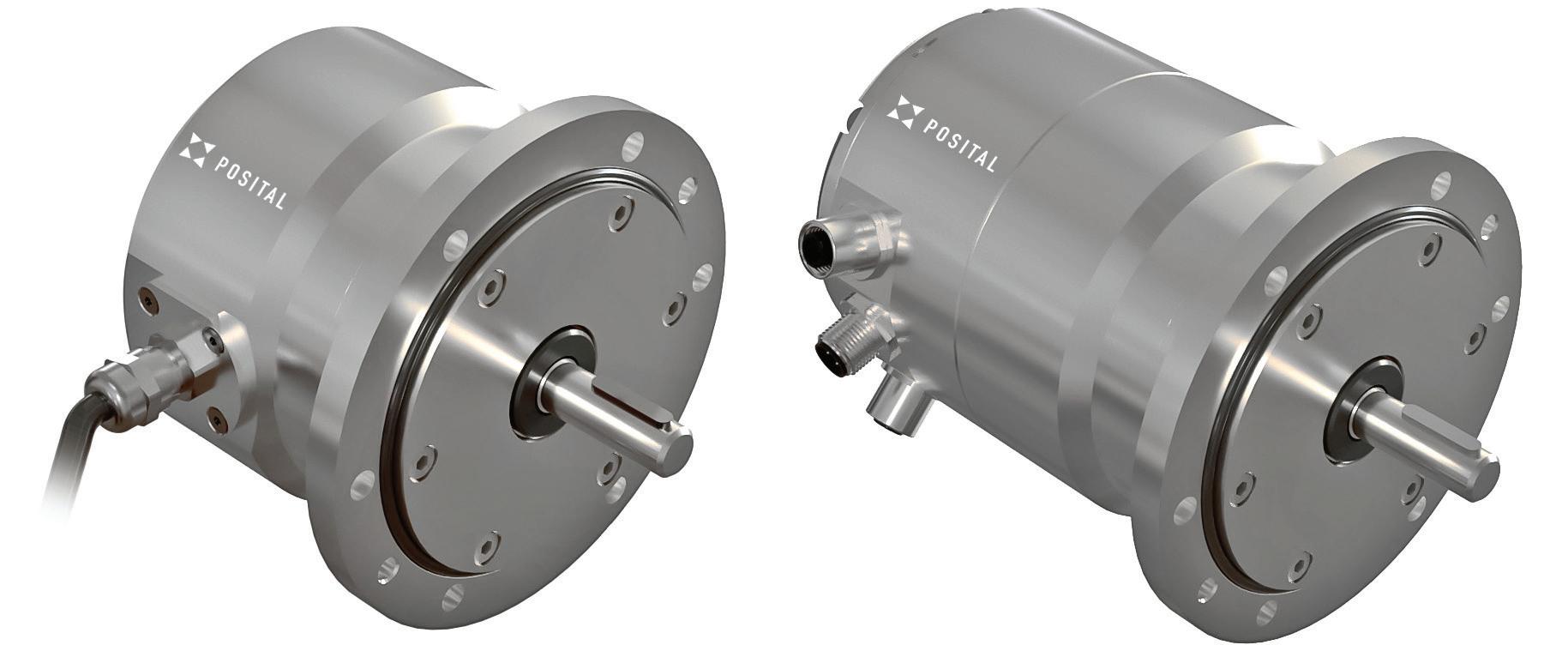
New POSITAL IXARC rotary encoders feature heavy-duty housings and shaft bearings to withstand radial shaft loads of up to 350 N and axial loads to 250 N. S, they excel in marine and offshore, crane, construction, and logging applications. The encoders also withstand shocks to 200 g and continuous vibrations to 20 g. Interfaces include PROFINET (RT or IRT), SSI, CANopen, EtherCAT and EtherNet/IP. Three M12 connectors on the housing let users daisychain devices together for more convenient cable layouts. Indicator LEDs on the endplate simplify system setup and troubleshooting. The output driver for incremental models also supports RS 422 (TTL) communications.
Synchronous serial interface uses two pairs of twisted wires for communication, per the RS-422 standard — one pair for differential data signals and one pair for differential clock signals. There are also two wires for power to the encoder. The clock frequency, or rate of data transmission, can be up to 1.5 MHz, depending on the length of the cable. To ensure data integrity, some SSI encoders support multiple transmission — also known as multipath or ringshift transmission —in which the same data is sent multiple times, and the controller compares the transmissions to ensure they match.
Bidirectional synchronous serial interface or BiSS: The bidirectional synchronous serial interface is an open protocol and is like SSI in that data transmission is synchronized by clock signals from the controller … but with BiSS, clock speeds up to 10 MHz are possible. BiSS also uses two twisted pairs of wires — one pair for data signals and one pair for clock signals — plus two wires for power.
Unlike SSI (which only supports unidirectional communication) BiSS supports bidirectional communication, meaning the controller can read from and write to nonvolatile memory in the encoder, where registers contain encoder identification information. BiSS encoders can also send data, such as temperature, to the controller on demand. Another unique feature of BiSS versus SSI is that within each data cycle, the primary control component determines and compensates for any transmission delay, allowing data transmission rates up to 10 Mbps.
The most current version of BiSS is BiSS-C (with C standing for continuously) although the interface is usually just called BiSS.
Unlike SSI encoders, BiSS encoders can be connected point-to-point or via bus. When connected via bus, the data from all the encoders is clocked (synchronized) to the primary control component in one continuous frame rather than individually. BiSS also implements a cyclic redundancy check (CRC) for error checking — a more reliable method than multiple transmission. There also exists a BiSS Safety interface for safety applications up to SIL3 per IEC 61508.
HIgh PERformance InterFACE Digital Servo Link — also called Hiperface DSL: This was originally a proprietary interface developed by SICK. However, in 2016, the interface was opened with a licensing model that lets other manufacturers integrate the technology into their product offerings.
Unlike its predecessor, Hiperface, Hiperface DSL is an all-digital protocol that uses just two wires for bi-directional communication and encoder power, bundled with the motor power cable
(although a transformer is required to improve the common mode noise rejection). This gives the advantage of eliminating the need for separate encoder connections on the motor and the controller. Hiperface DSL complies with the RS-485 standard and and has a data transmission rate of 9.375 Mbaud. Data can be transmitted cyclically (as fast as possible) or synchronously with the controller clock.
The Hiperface DSL architecture also includes channels for the transfer of motor parameter data, condition monitoring data, and integrated safe motion, with data being transmitted over two digital communication wires. This redundancy and error-checking make the Hiperface DSL interface compliant with SIL3 safety standards.
Encoder Data or EnDat: This proprietary interface from HEIDENHAIN is a synchronous, bidirectional standard that uses four wires for communication — two wires each for differential data and differential clock signals — plus
two wires for power and two for either battery buffering or parallel power supply. EnDat can provide clock frequencies of up to 2 MHz, and on some models, additional compensation for propagation delay makes frequencies up to 16 MHz possible. Because Hiperface DSL has become an open interface, EnDat is now the only serial interface for absolute encoders that remains proprietary … although it should be noted that the original Hiperface protocol also remains proprietary.
The latest EnDat can also read, write, or update information stored in the encoder … and can transfer data such as sensor information or diagnostic information from the encoder to the controller. The type of data transmitted (such as absolute position, diagnostics, or parameter information) is sent via mode commands from the controller to the encoder. Like BiSS and Hiperface DSL, EnDat is also compliant with SIL3 safety standards. DW
Michael G. Giunta VP/ Mechanical Engineer
Macron Dynamics Inc.
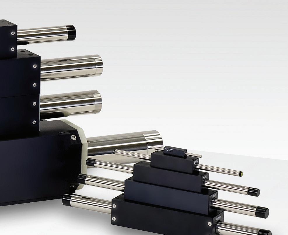
A review of the different types of linear actuators reveals how to choose the best solution based on the particular application requirements.
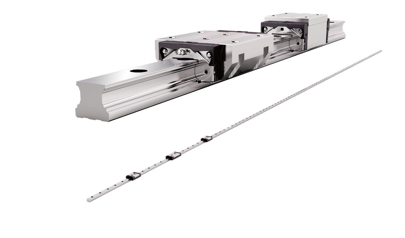
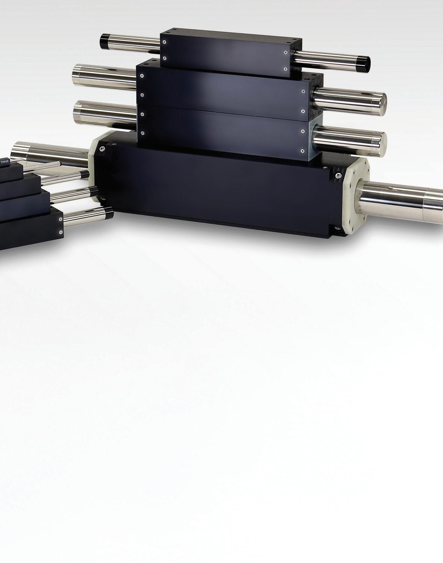
Linear motors come in a variety of types, including iron core platen style, ironless T- or U-channel, or tubular style.
Pulse America
Linear actuation, or moving a load in a straight path, can be accomplished using a variety of methods. Each actuator type has features and performance capabilities inherent in the base technology associated with the actuator. Here, we review the six different types of commercially available linear actuators and illustrate how to choose the best one based on the particular application requirements.
What is linear motion?
Linear motion is defined as movement along a straight line and can be described mathematically with just one spatial dimension. Linear motion can be uniform (constant velocity or zero acceleration) or non-uniform (variable velocity or non-zero acceleration). The linear motion can be in any direction —–vertical, horizontal, or at any angle.
There are six major types of linear actuators, which include:
• Pneumatic cylinders (rod or carriage style)
• Hydraulic cylinders (rod style)
• Screw-driven actuators (rod or carriage style)
• Belt-driven actuators (carriage style)
• Linear motors (carriage or rod style)
• Telescoping actuator
All of these technologies can be operated as either a rod and/or carriage style actuator. Each style has specific capabilities that determine the applications to which they can be applied.
Carriage Style – This style of actuator has a carriage or slider that is supported by a rail system braced at both ends. The support structure can consist of a round or profile rail or other slider mechanism that supports the moment load carried by the carriage. Forces applied to the carriage move the load back and forth along the rail system.
Rod Style – These consist of a rod (typically round), supported by a bushing at the front end, that extends and retracts from the mechanism housing. The rod style actuator is only intended to push or pull a load in the axial direction and does not support side or moment loads.
The force source (fluid/air or electric) – or how the actuator is driven, is an important consideration for both carriage and rod style actuators. Hydraulic and pneumatic actuators use hydraulic fluid or compressed air that
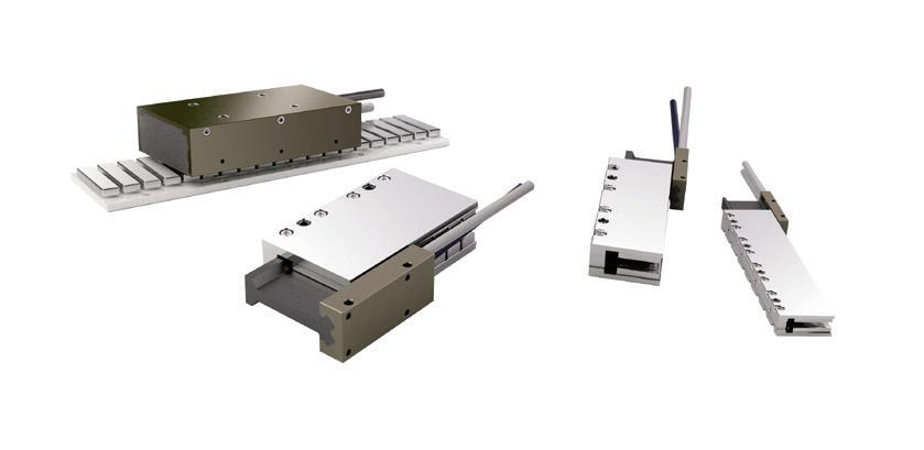
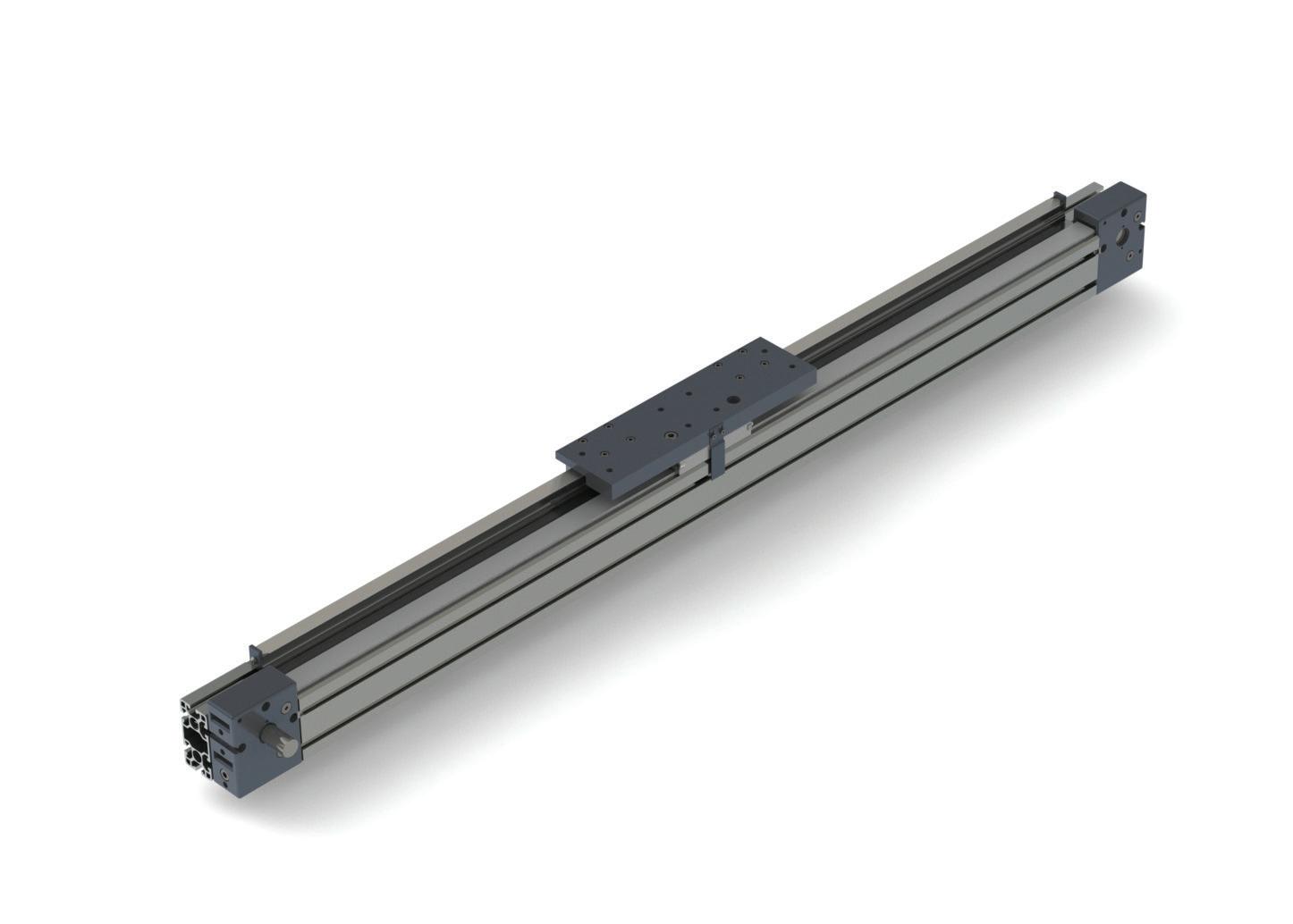
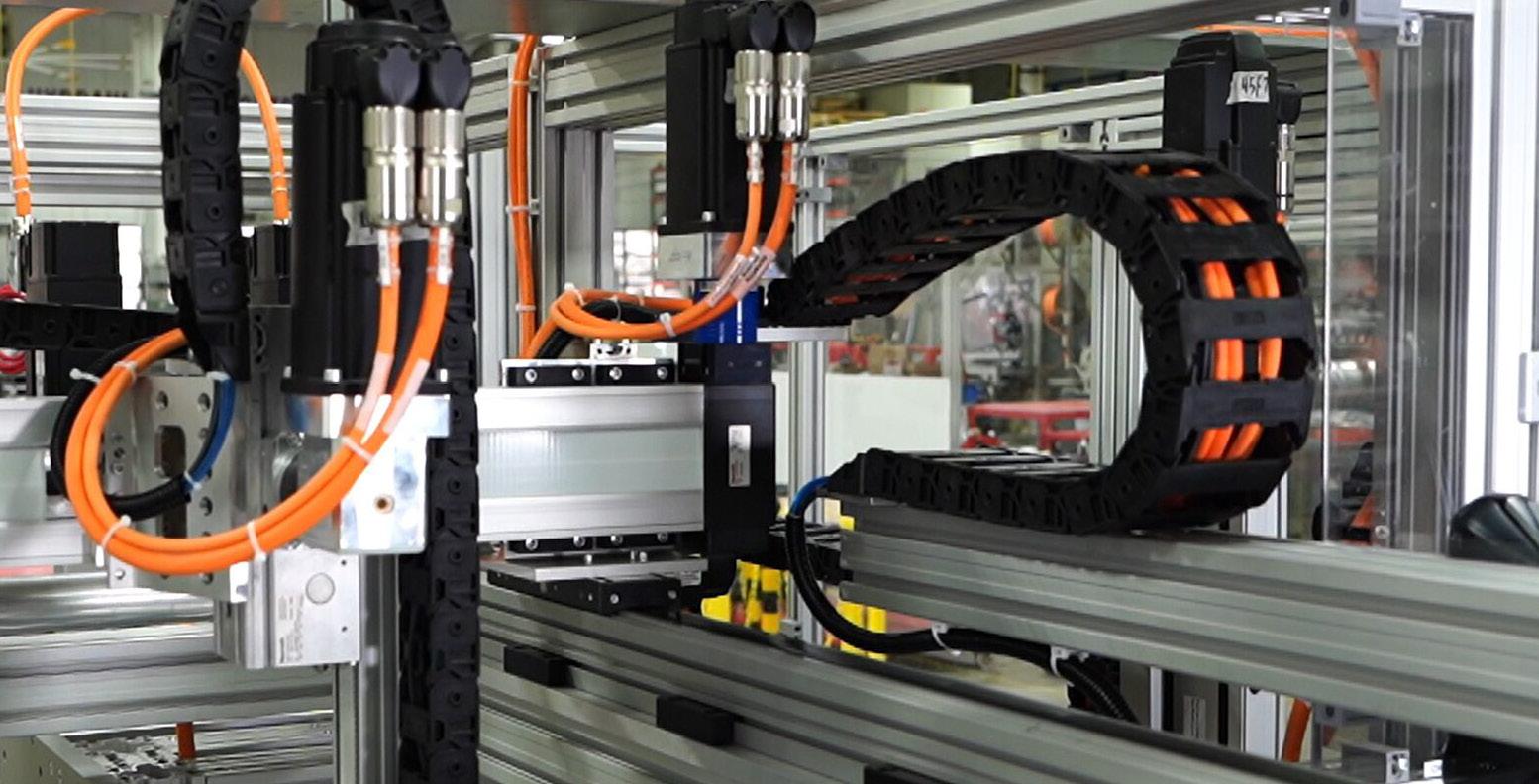
Belt actuators can operate at high speeds and offer quick accelerations.
Macron Dynamics
Nippon
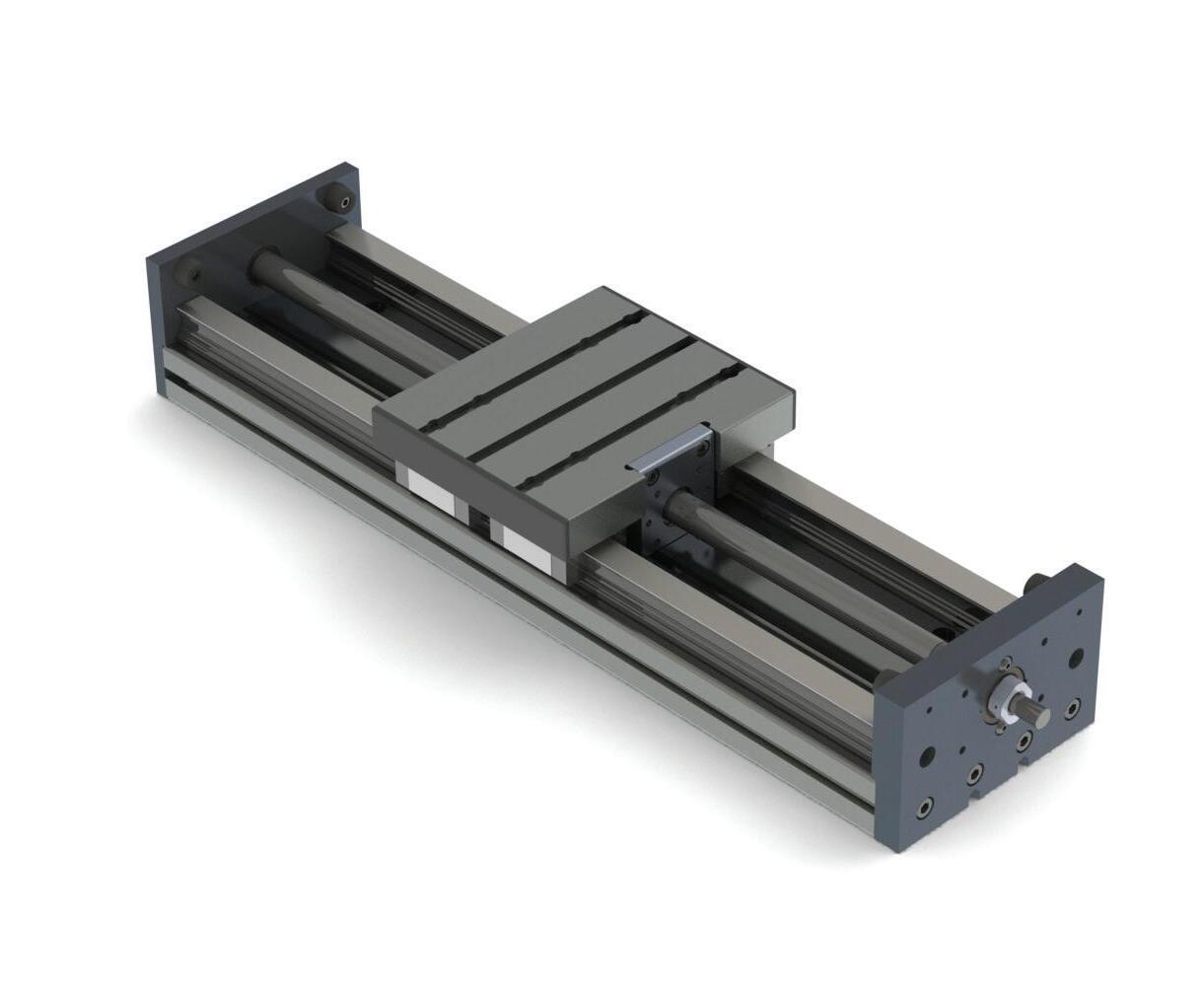
Screw actuators excel in load carrying applications that require high levels of position and speed control. Macron Dynamics
PERFORMANCE PROPERTIES
• NASA Low Outgassing
• Cryogenically serviceable
• Thermally conductive
• Electrically Insulative
• High bond strength
is delivered to the actuator mechanism through a pump or compression system. A control element regulates the air flow and pressure through the actuator to create force and motion. With electrical actuators, power is applied to an amplifier/controller that regulates the flow of current and voltage into the electrical motor to deliver force and motion. Typically, the power and control sources are housed in a control cabinet or machine closet with the power delivered to the actuator via hoses and valves (hydraulics/pneumatics) or cables (electric). With advances in power stages and electronic controls, integrated drive/actuator designs are becoming more common.
Comparison of six different types of commercially available actuators
Pneumatic cylinders
Pneumatics, as a means to create a force to move objects, emerged in 1829 with the development of the compound air compressor. In 1867, Alfred Beach introduced a pneumatic subway train in New York City that illustrated how passengers could be transported in a vehicle pushed through a tube by pneumatic power. Pneumatic actuators
Motion Redefined
As the world’s first ESV, we solve motion control challenges with ingenuity. Evolution Motion Solutions combines over 80 years of industry expertise to deliver technically superior factory automation solutions that drive efficiency, precision, and performance. Our expertise in concept engineering, systems integration, and value-add distribution ensures your machines and systems run at peak performance—reducing downtime, optimizing production, and increasing throughput. From battery EV and fast-moving consumer goods to automotive and warehouse automation, we help manufacturers stay ahead with control solutions built for the future.
evolved through the industrial revolution and maintain a place in linear actuation today.
In a pneumatic cylinder, air is used to move a piston back and forth in either a rod or carriage style actuator. While the technology is mature, simple, and cost effective, there are distinct advantages and disadvantages to pneumatic actuation systems.
Typical uses include pressing applications, some load carrying applications with simple quick indexing, or applications with high shock loads. The simple design and maturity of this technology helps minimize the upfront costs to implement a pneumatic system in basic applications. The evolution of compressors, valve designs, and sophisticated control electronics allow high speeds and fast accelerations. Basic pneumatic systems are not ideal for precise positioning applications and are not as energy efficient as alternate technologies, which results in higher energy and lifetime costs.
Hydraulic cylinders
Hydraulics, much like pneumatics, evolved into a major industrial technology during the industrial revolution. Blaise Pascal discovered in the 1650s that pressure could be transmitted through a fluid. Early hydraulic cylinders powered by hand pumps were used in cranes, presses, and various industrial machinery.
In a hydraulic cylinder, fluid is used to move a piston back and forth in a rod style actuator. While this technology is also mature, simple, and cost effective, there are distinct advantages and disadvantages to hydraulic actuation systems.
Typical applications include high force pressing (push/pull), extreme shock loads (like earth movers), and large industrial tractors. Hydraulics are durable and can operate for extended periods if properly maintained. The simple design and maturity of this technology helps minimize upfront implementation costs. When compared to other technologies, hydraulic systems may take more real estate to accommodate the required fluid storage and pumping system, tend to produce higher noise levels, and are not as efficient. Hydraulics can also leak, which creates both maintenance and environmental concerns. The inefficiencies of a hydraulic system, combined with the hydraulic oils required for operation, may necessitate alternatives in industrial applications.
Screw-driven actuators
Pneumatic and hydraulic actuators create linear force through controlled fluid/air pressure. Screw-driven actuators use mechanical leverage to create a linear force. Screw actuators are driven by an electric motor to rotate a screw. The linear force is created by connecting a nut to the screw and translating the rotary motion of the motor and screw into a linear motion as the nut moves back and forth along the fixed screw.
Screw actuators are excellent for load carrying applications that require high levels of position and speed control; such as machine tools, packaging machinery, converting machinery, and many factory
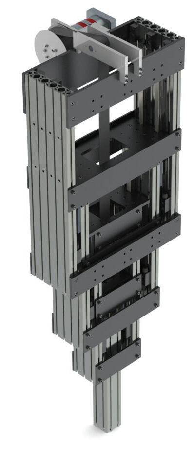
Telescoping actuators are typically used in vertical lifting applications to extend or retract a load. Macron Dynamics
automation and hydraulic applications. Screw actuators are available from extremely small to quite large to handle a wide range of loads. They perform comparably to hydraulics at high loads but cannot achieve the highest forces of hydraulics. Their modular design minimizes installation time because no air compressors, pumps, hoses, tubing, or valves are required. The minimal maintenance, since it is limited to the actuator itself, just requires occasional lubrication and inspection for wear and tear. The electric motors used to drive the screws, along with the efficient translation of rotary torque into linear force, provide an overall efficient system.
Belt-driven actuators
Belt actuators, like screw actuators, are driven using an electric motor. A belt actuator, however, incorporates a belt and pully system instead of a screw. The linear force is created by connecting the belt and pully system to the rotary motion of the motor. The belt then translates to a linear motion as the belt rotates back and forth around the pulleys.
Belt actuators are excellent choices for high-speed indexing applications that require position and speed control, such as multi-axis cartesian and long span gantry systems, but are not recommended for pressing applications. Belt actuators can operate at high speeds and offer quick accelerations. The electric motors used to drive the belts, along with the efficient translation of rotary torque into linear force, provides an overall efficient system. While certain types of belts tend to stretch over time, material improvements and new belt technologies have mitigated this issue. Many belt actuators are supplied with pretensioned belts. With proper maintenance, belt actuators can operate over a long lifespan.
Coming Soon From Dorner!
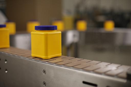
Dorner’s new C belted curve conveyor offers an economical and gentle material handling solution for production line configurations with curves and turns.
Packaging Applications
Sanitary Applications
Designed for Flexibility
Linear motor actuators
Linear motor actuators are direct-drive solutions that contain no mechanical transmission elements. The load is connected directly to the carriage assembly and is moved by the linear motor itself. Linear motors are available in a variety of types, including iron core platen style, ironless T- or U-channel style, or tubular style. Linear actuators are typically based on a BLDC servo motor and use linear encoders for position and commutation control. Depending on the application requirements, the more compact and efficient linear motors are potential alternatives for belt or screw-driven actuators and pneumatic or hydraulic systems. They are particularly excellent choices for multi-axis cartesian or gantry systems where fast move and settle times and precision are important. Linear motors are capable of high speeds and
quick accelerations and are typically only limited by the available current and capabilities of the linear rails to which they are mounted. Linear motor systems are inherently compact, as many transmission elements are eliminated, and can be constructed with low profiles for space saving requirements. With reduced energy consumption, efficient linear motors, and the elimination of hydraulic fluids, linear motor actuators are an environmentally friendly approach.
Telescoping actuators
Telescoping actuators are similar to the rod style actuator but are designed to expand to two to three times their collapsed length through embedded segments within the actuator body. These actuators are typically used in vertical lifting applications to extend or retract a load. They can be screw or
Screw types
There are three styles of screws that can be incorporated into a screw-driven actuator — roller, ball, and lead screws. Each screw type has specific advantages and related cost implications with each available in a variety of leads that identify the distance of linear motion per one rotation of the screw. For example, a 5-mm lead results in 5 mm of linear motion for one screw rotation. Performance characteristics of screws are based on the lead to force to speed profile. It’s important to understand the application motion profile and how that overlays the screw performance characteristics to properly size and select the appropriate screw. Each of the three screw types have different characteristics that determine the best fit for each application.
• Roller screws – Developed in the 1960s, this screw is a unique design using a planetary screw mechanism that helps distribute the load over a greater surface area to improve screw life. Speeds up to 60 in./sec are possible with a roller screw.
belt-driven with servo or stepper motors. Pneumatic and hydraulic systems are also a possibility with telescoping actuators.
Typical applications are to raise and lower various loads or to insert or retract parts into another machine process. Depending on the actuation technology, the telescoping actuator can handle midload ratings and may use screw or belt actuators to provide rugged designs and extended life. The telescoping actuator is not ideal for horizontal applications due to potential moment load deflection when fully extended. DW
Macron Dynamics www.macrondynamics.com
However, roller screws are expensive, but offer significant value for load capacity, speed, and durability.
• Ball screws – The ball screw was patented in the late 1800s when the traditional lead or acme screw incorporated a nut with ball bearings to reduce friction. This design improved efficiency and reduced wear. The ball screw evolved into an industry standard used across industries of all types. Ball screws have lower maximum speeds than roller screws with linear speeds that approach 24 to 30 in./sec.
• Lead screws – The lead screw likely first appeared in ancient Greece. Its use in industry traces back to the industrial revolution when metal cutting lathes began to be perfected. The lead screw is a costeffective solution for translating rotary to linear motion. Lead screws are less efficient, but have the inherent feature of being self-locking, making them ideal for vertical applications, as opposed to the ball or roller screws that are back drivable.
Italian machine builders are set to showcase their cutting-edge ‘Breaking Necks’ solutions and technologies
Italian machine builders are the key to unlocking your strategic business potential.
How are end users leveraging Italian machinery to advance their operational goals and address significant industry trends? Machines Italia’s Spring 2025 issue will explore key trends across various sectors utilizing Italian machinery, including advancements in automation, environmental sustainability, and the increasing demand for flexible and adaptable machinery. For more details, visit machinesitalia.org
Test & Measurement
This article begins by defining jitter, then looks at its component jitters, compares bit jitter with clock jitter, considers how jitter can be measured using an eye diagram, and closes by looking at acceptable levels of jitter.
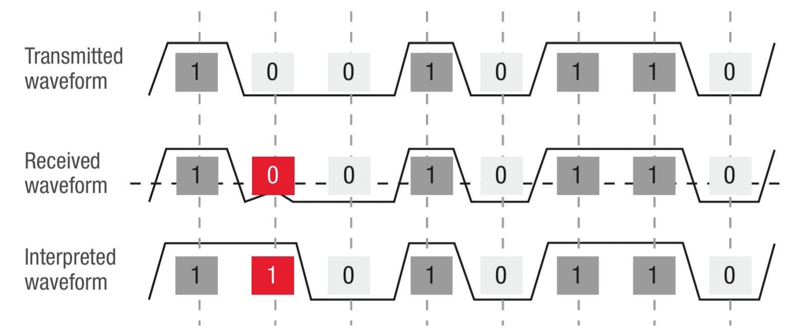
Bit jitter is the small variation in the timing of individual bits in a data stream. It’s manifested in how early or late a signal transition occurs compared with the time it should transition. Communication errors can happen when jitter becomes so large that the signal appears on the wrong side of the transition threshold at the sampling point. That can cause the bit to be misinterpreted and cause a transmission error (Figure 1).
There are two general types of jitters; bounded jitter, also called deterministic jitter, and unbounded jitter, also called random jitter. Unbounded
jitter sources don’t reach a maximum or minimum deviation within any time interval. It can be caused by sources like thermal noise, trace width variations, and so on.
There are two types of deterministic jitters: periodic jitter and data-driven jitter. Periodic jitter has a fixed frequency, and sources can include power supply noise and crosstalk between data lines. Data-driven jitter is related to transitions in the data stream. For example, a stream of alternating bits like 01010101 would have a different characteristic compared with a transition that follows a long series of the same bit, like 000011000011.
Bit jitter vs clock jitter
Clock jitter refers to the timing variations in the clock signal. Clock jitter can be one cause of bit jitter. But clock jitter can
Bit jitter can be a problem. A digital data stream is composed of a series of rapidly changing “ones” and “zeros.” Bit jitter can make it difficult to tell the difference, resulting in data errors.
cause larger problems with the timing of the entire data stream. Applications like 5G telephone require highly precise clocks to ensure reliable communication. In these systems, jitter is measured in picoseconds and characterized by its RMS value. Like bit jitter, clock jitter has several component jitters:
• Random, or intrinsic, jitter is inherent in a system and is usually caused by thermal noise, trace width variations, and so on.
• Deterministic jitter refers to repeatable variations in clock timing and can be caused by power supply ripple or crosstalk.
• Phase jitter also affects the timing of data transitions and is the time domain view of the phase noise that is measured in the frequency domain of a clock.
Jeff Shepard • Contributing Editor
What does jitter look like?
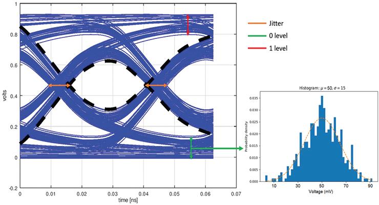
One way jitter can be seen is by using an oscilloscope to produce an eye diagram that superimposes the rising and falling edges of a bitstream over time. Variations can be visualized and quantified leading to bit error rates.
The horizontal spread of the signal transitions at the crossing point of the eye can be used to measure jitter. Most oscilloscopes can automatically generate a histogram based on the distribution of the edge timings. The width of the histogram illustrates the jitter level (Figure 2).
What is an acceptable jitter?
Jitter can be controlled, but not usually eliminated. The acceptable level of jitter depends on the application. There are no standards that govern the acceptable level of jitter. 5G communication systems need very low levels of jitter, often in the range from 1ps down to tens of fs, other guidelines include:
• Voice over internet protocol (VoIP) calls typically require jitter to be less than 150 ms.
• Video calls have different requirements. Usually, jitter needs to be under 30 ms, but if the video does not include rapid motion, jitter up to 200 ms may be acceptable.
• Online gaming and live streaming often require that jitter be less than 50 ms.
Summary
Bit jitter is the slight variation in the timing of individual bits in a data stream
and can result in data errors. Bit jitter can be bounded (deterministic) or unbounded (random). The two types have different causes, but both can be viewed and measured using an oscilloscope. The level of acceptable jitter is strongly application-dependent and can range from a few fs up to tens of ms. DW
2. The eye diagram on the left illustrates the effect of jitter and was used to capture statistics for the 0-level histogram on the right.
FIGURE 1. Jitter can cause misinterpretation of bits (red) and result in data errors. Keysight
FIGURE
Altium
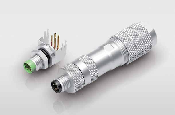
Connectors
What’s a
thermal connector?
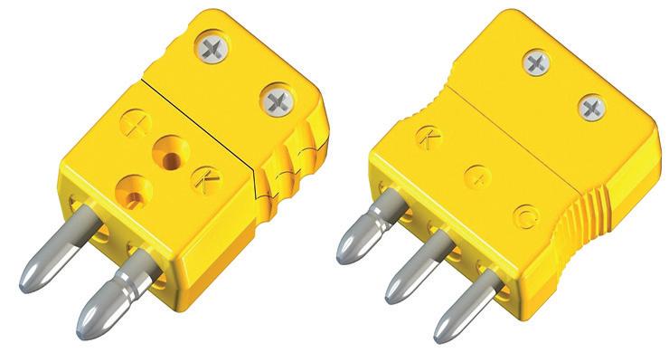
A thermal connector, sometimes called a cold-end termination, is designed to connect temperature sensors to measuring instruments, like thermocouples or resistance temperature detectors (RTDs).
Jeff Shepard • Contributing Editor
Thermocouples and RTD connectors are used in a wide range of scientific and industrial systems in aerospace, chemical, food and beverage, oil and gas, pharmaceutical, and nuclear power generation.
Two standard thermocouple connector sizes are available to fit the needs of specific instruments. Standard (large) connectors measure 35 mm long, 25.4 mm wide, and 12.8 mm thick; their round pins are approximately 15mm long.
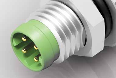
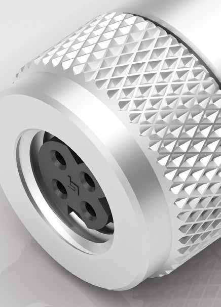
Miniature connectors are about half the size of standard units and have flat pins and sockets. The pins and sockets on both sizes are polarized to prevent miss mating. Thermal connectors are available in several common pin configurations, including (Figure 1):
• 2-pin configurations are the most common and are used with a singlecircuit thermocouple or RTD.
• 3-pin configurations that add a ground pin for single-circuit, threewire RTD sensors.
• 4-pin designs are used for two thermocouple or RTD circuits or a single-circuit, four-wire RTD sensor.
What are thermal connector contacts made with?
A thermocouple generates a voltage based on the temperature difference between two dissimilar metals joined together at a junction. To avoid
introducing errors in the temperature measurement, the contacts in a thermocouple connector are made from the same material as the thermocouple wires.
FIGURE 1. Examples of a two-pin thermocouple connector and a threepin RTD connector.
Technical Equipment Sales
TYPE CODE INSERT MAT’L ALLOY COLOR CODE POSITIVE NEGATIVE GROUND
J Iron Constantan Copper Black
T Copper Constantan Copper Blue
K Chromel™ Alumel™ Copper Yellow
N Nicrosil Nisil Copper Orange
R Copper #11 Alloy Copper Green
S Copper #11 Alloy Copper Green
E Chromel™ Constantan Copper Violet
U Copper Copper Copper White
C #405 Alloy #426 Alloy Copper Brown
1,2,3* (2) Copper (3) Copper (1) Copper White
All Hi-Temp Connectors Red
TABLE 1. The various types of thermocouples and RTD connectors have positive and negative contacts made with specific materials to ensure the accuracy of temperature measurements. Technical Equipment Sales * FOR RTD 3-WIRE APPLICATIONS
An RTD measures temperature changes based on the resistance change in a platinum wire. Its connectors use copper contacts. RTDs can offer higher accuracy, especially in precise temperature ranges, while thermocouples are available for a wider range of temperatures.
The American National Standards Institute (ANSI) and the International Organization for Standardization (ISA) have defined a series of thermocouple codes (letters and colors) that indicate the type of metal used in the thermocouple’s wiring and the temperature range it can withstand. Thermal connectors have contact materials optimized for each type of thermocouple or RTD (Table 1).
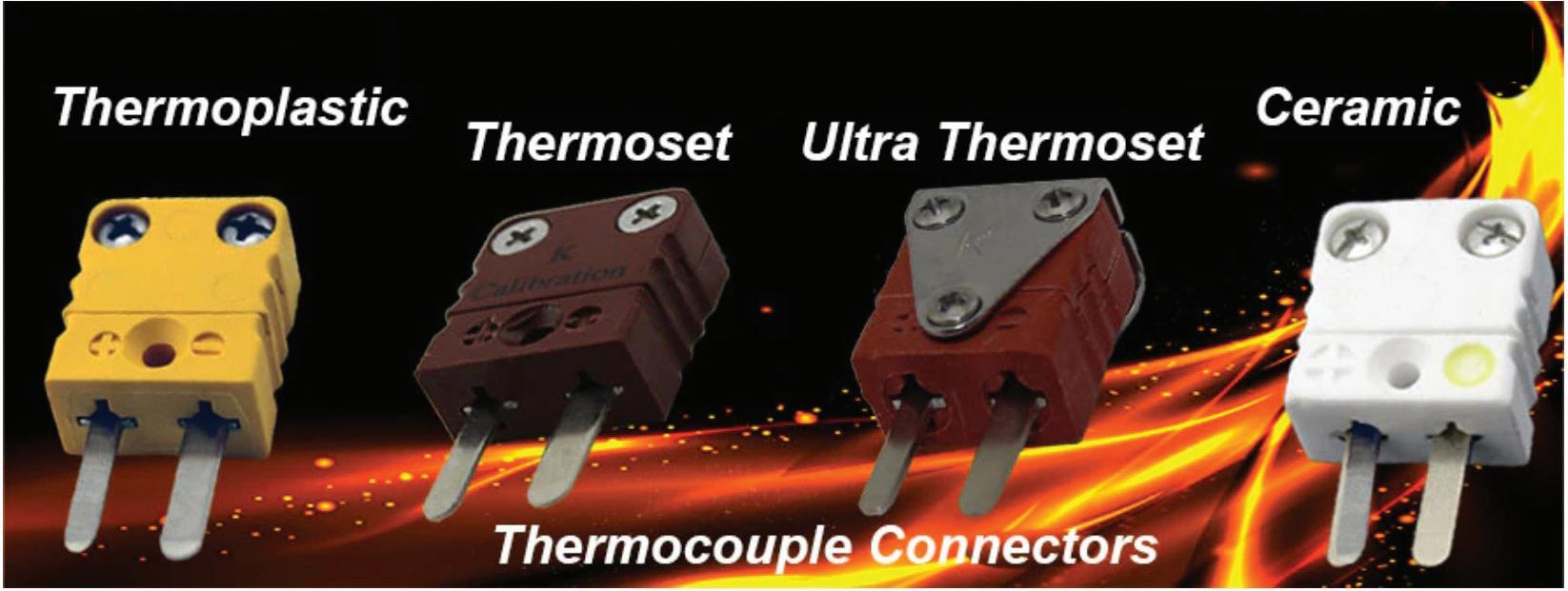
What materials are used in the connector bodies?
Stainless steel is often used for RTD connector bodies due to its durability, corrosion resistance, and ability to withstand a range of temperatures. Stainless steel is also suited for industrial applications where many RTDs are employed.
Thermoplastic is the most common material used for thermocouple connectors. It provides a good combination of mechanical strength, temperature resistance, and cost and can be used in applications from about -40 to 200 °C.
Glass-filled thermosets are less durable but, depending on the formulation, can withstand
Connectors
temperatures from 350 to 425°C. Ceramics can be used in hightemperature applications to 650 °C or higher, but they are fragile and the most expensive (Figure 2).
Color-coding
Many applications include multiple types of thermocouples. To ensure correct connections and the use of the proper thermocouple, the lead wires are color-
coded. In the U.S., the color coding is defined in ANSI/ISA MC96.1.
Different insulation colors simplify the identification of thermocouple types, ensuring that the correct device is used in each application. The colors also indicate the polarity of the leads to ensure proper insertion into the thermal connector.
Thermocouples are subject to “aging,” which causes them to
WHEN PRECISION MATTERS.
2. Thermocouple connector bodies are made with materials designed for specific temperature ranges.
Evolution Sensors and Controls
become less accurate over time due to high-temperature operation and environmental conditions. In a standard environment, thermocouples may need to be replaced every 1 to 3 years. Color coding speeds up the replacement process.
Summary
Accurate temperature measurements are important in various industrial and scientific applications. Properly designed thermal connectors help ensure the accuracy of those measurements and can speed up the replacement of wornout thermocouples and RTDs. Because of the various thermocouple designs, the leads are color-coded to speed the identification of devices and their polarity. DW
• Thermocouple Connector Guide, Evolution Sensor, and Controls
• Thermocouple Connectors, IOThrifty
• Thermocouple Connectors Explained – All You Need To Know, Connectronics
• What Are Temperature Sensor Connectors (Plugs & Sockets)?, Peak Sensors
FIGURE
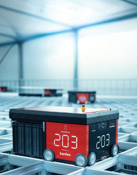
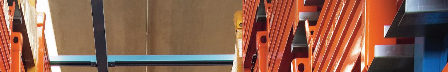
SOLVING OMNICHANNEL OBSTACLES WITH
STORAGE AUTOMATED & RETRIEVAL
STEPHANIE NEIL • EXECUTIVE EDITOR
AUTOMATED ORDER PICKING SETS UP APPAREL COMPANY CUTTER & BUCK FOR FUTURE GROWTH.
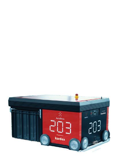
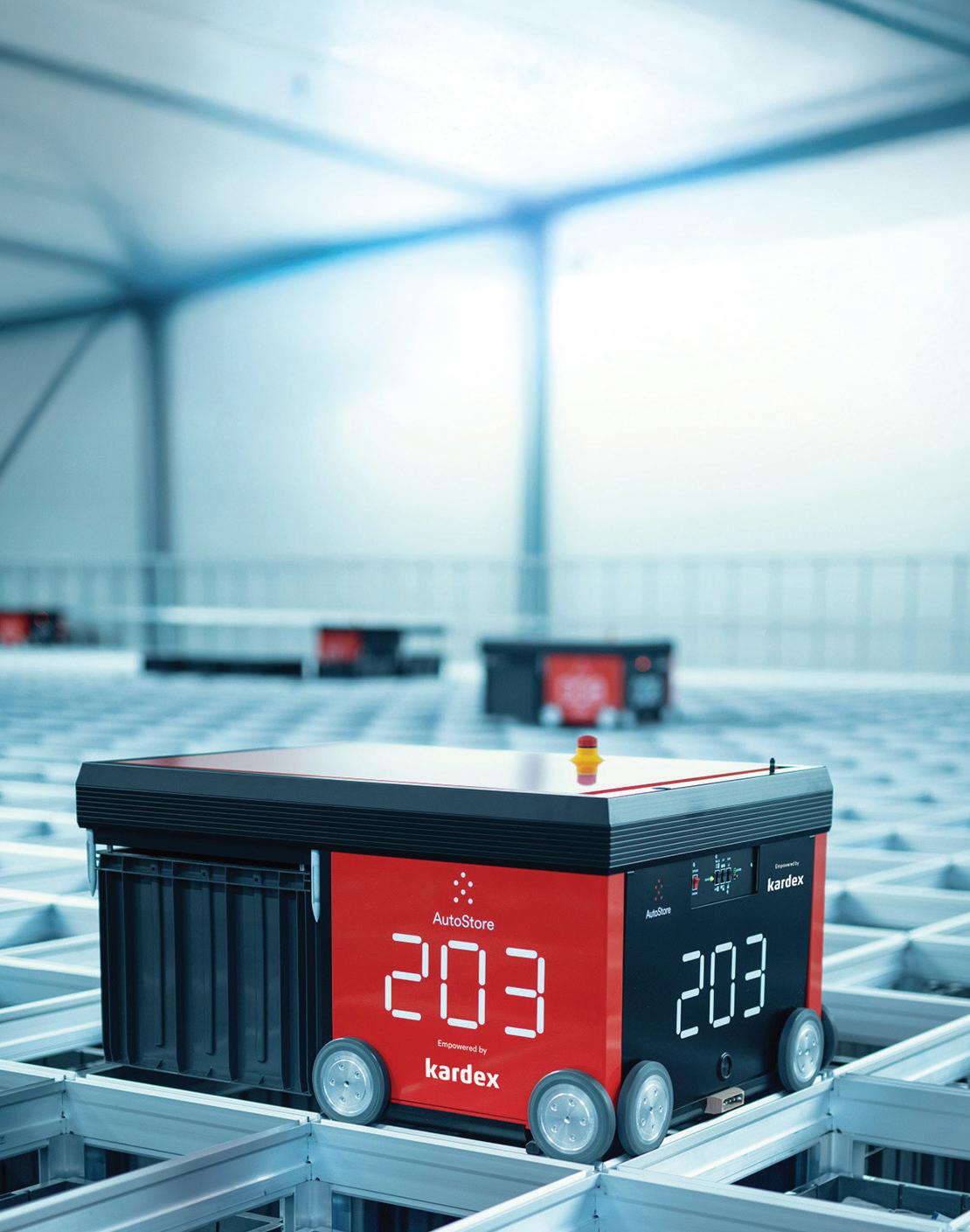
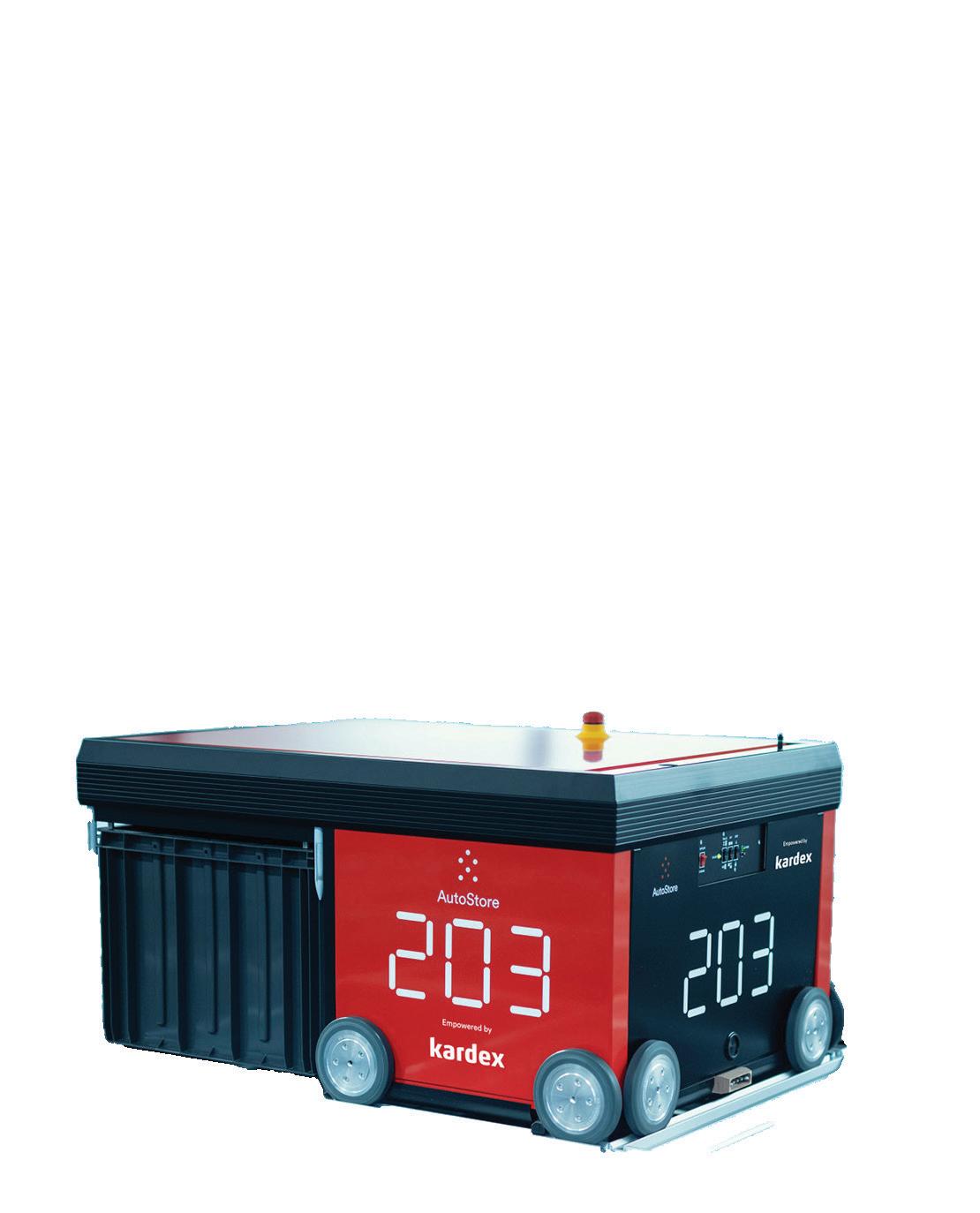
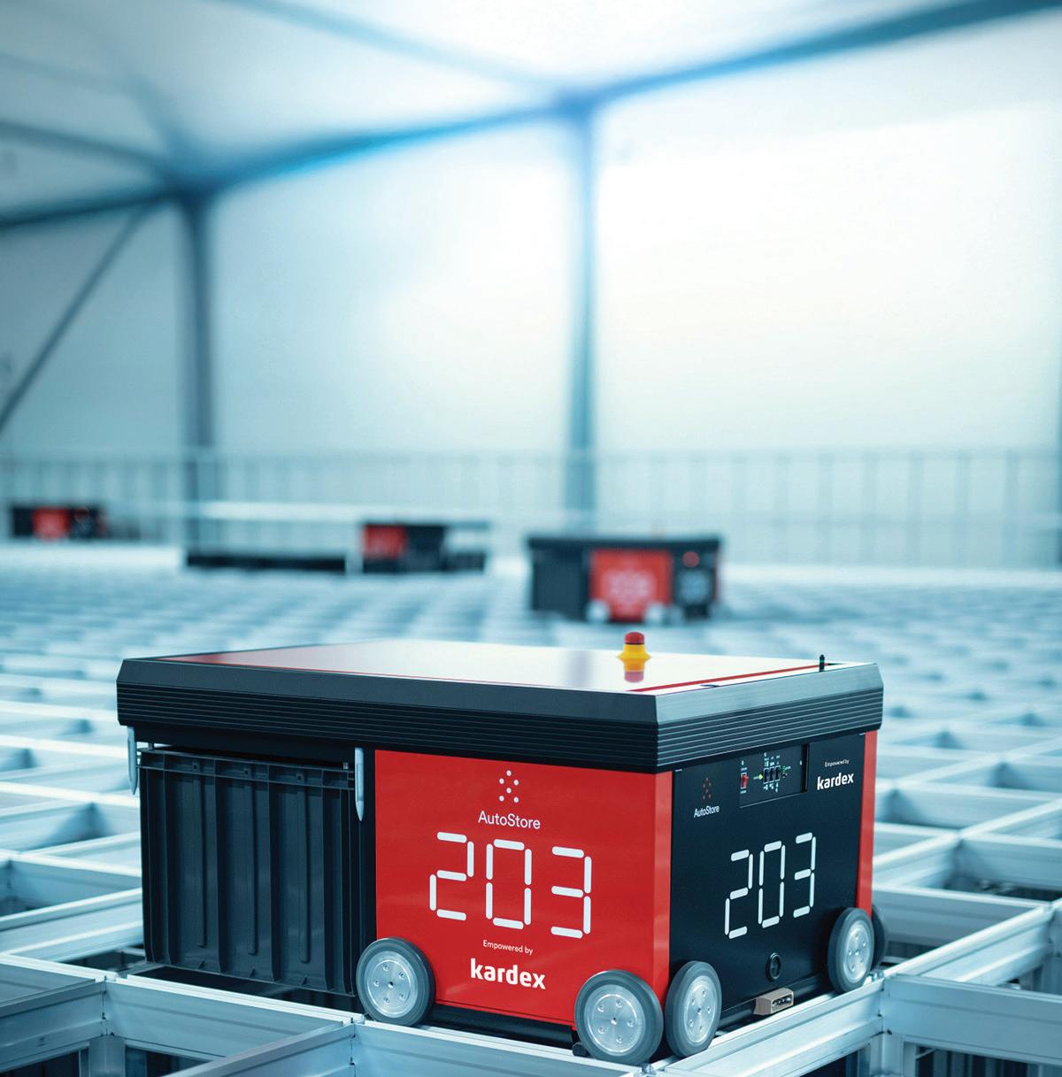
The AutoStore automated storage and retrieval system working with the Kardex warehouse execution system was designed to meet Cutter & Buck’s five-year growth plan. Kardex
There's nothing like a pandemic, a labor shortage, and the holiday season to expose inefficiencies in a fulfillment center and open executives' eyes to the need for a new automated infrastructure. That's exactly what happened at Cutter & Buck, a Seattle-based omnichannel retailer hit with this troubling trifecta in 2020.
Known for its lifestyle apparel and upscale activewear, this brand has evolved over the years to provide custom embroidery, licensed products, and specialty retail. With that product expansion came the need to manage different workflows for direct-toconsumer sales, retail outlets, and customized clothing.
However, the growing e-commerce channel pushed the limits of Cutter & Buck's fulfillment capabilities, especially as online shoppers expected same-day shipments. This on-demand consumer mentality puts pressure on staff and the systems in place for order picking.
"We were running out of daylight trying to condense more and more
AUTOMATED WAREHOUSE
Cutter & Buck online orders can be picked, packed, and on its way to shipping in less than 10 minutes. AutoStore
orders into a shorter and shorter turn time," said Cutter & Buck CEO Joel Freet.
This was particularly trying during the COVID-19 pandemic when the company struggled with surging online sales and a simultaneous labor shortage. During this time, even the leadership team stepped in to fill orders in the company’s facility in Renton, Wash.
"We all pitched in, getting trained on our picking processes and committing to multiple shifts per week during the holidays," Freet recalled. "By holiday 2021, our e-commerce was growing so fast, we had no choice but to pitch in again."
The distribution center layout of three floors and 21 aisles required a lot of running around to build a cart, put orders into totes, and send them onto the conveyor to operations.
"It seemed automated at the time, but you were walking eight to 10 miles a day when doing that picking operation," Freet explained.
This was an eye-opening turning point for the leadership team, which
decided to explore new ways to make the existing processes more efficient. It investigated changing the layout of the picking module, reducing SKUs, or adding more automation.
"In the end, we uncovered that to keep up with our growth, we would need a breakthrough in productivity to support our peak season sales in the future,” said Freet. “And that's what brought us to looking at next-generation picking automation systems.”
After many technology demonstrations, Cutter & Buck decided to upgrade its facility with AutoStore's automated storage and retrieval system (ASRS) coupled with the FulfillX warehouse execution system (WES) from Kardex.
Team analyzes and accelerates picking processes
The Kardex team helped Cutter & Buck implement the ASRS and WES, starting with an overall assessment of the facility.
"They looked at our product sales, our order flow, the number of lines we pick per hour, and they were able
to analyze all that and tell us how we could configure our AutoStore set up to give us that boost in our business that we were looking for," Freet noted.
According to Scott Sumpter, executive director of distribution at Cutter & Buck, the 10,000-sq.ft. AutoStore ASRS was deployed quickly, and it immediately changed the workflow. For example, during peak season, 12 associates working with AutoStore managed volumes that previously required 30 workers.
AutoStore's goods-to-person (G2P) approach keeps pickers stationary at ports, while robots retrieve totes from the high-density storage grid and deliver them to workstations. This eliminates travel time within the warehouse, enabling faster and more accurate picks.
"The solution has absolutely helped us with our picking efficiency," said Sumpter. "We are not only shipping same day for blank orders consistently with no real challenge; now we've [also] been able to reduce our time for embroidery processes, allowing faster turns there. It is because the AutoStore
system is getting orders out to shipping or to embroidery very quickly."
In addition, the intuitive software interface and visual guidance make training easy.
"We can teach people to be productive pickers in about 10 minutes, and a good part of that is safety protocols we go through," Sumpter said.
Kardex FulfillX also provides a way to expedite orders when needed, a capability Cutter & Buck never had before.
"So, now, within 10 minutes, we can pick any order that we want to come out first," said Sumpter.
Future
fulfillment includes an engaged workforce
The AutoStore system was designed to handle five years of growth at Cutter
& Buck. Not only does it ease and accelerate the picking process, but it also supports the consumer’s need for a quick turnaround.
For example, the ASRS supports direct-to-consumer orders by picking items directly into shipping cartons. When an order comes into the website, it goes into a pick ticket, and it is picked, packed, and on its way in less than 10 minutes.
Goods for embroidery are picked into totes and staged near production areas for immediate use. But the system's dense storage capacity has allowed Cutter & Buck to repurpose a former three-day work-in-progress staging area for miscellaneous storage.
According to Freet, the primary goal for adopting an ASRS was to eliminate bottlenecks and enable
more efficient labor allocation – not to reduce headcount. The implementation delivered on that and resulted in improved service levels and faster order fulfillment across all channels.
"I think our ability to commit to the fastest service levels that we possibly can has been really positive for the company," Sumpter said. "Our AutoStore deployment has been critical to removing the bottleneck in picking that was previously challenging our ability to hit those high service levels year-round."
It is also a positive shift for personnel, as the workforce is much more engaged. "It's stuff that is getting people ready for the next generation and keeping them excited about working here," Freet said. AW
The Senhance system is designed to work with 5- and 3-mm instruments.
Asensus Robotics
By Brianna Wessling • The Robot Report
GALLBLADDER REMOVAL
Reven Alt, a 16-year-old from Aurora, Colo., last year became the first patient to be operated on by a remotely controlled Senhance robot at HCA HealthONE Rocky Mountain Children’s. After the removal of his gallbladder with the Asensus Surgical system, Rev was discharged that afternoon. Just two days later, the teenager was out of the hospital and dancing at his prom.
In the past, common procedures such as gallbladder removal could mean a night or more in the hospital, and weeks of painful recovery.
Now, systems like the one from Asensus Surgical promise to make them
faster, less invasive, and safer. In addition, the company is bringing this technology to pediatrics, a notoriously tricky area for surgeons.
Dr. Steve Rothenberg, the surgeon who performed the procedure, said his patients can weigh anywhere from less than 1 lb. to over 250 lbs.
“There’s a huge range of patients that I have to deal with,” he told The Robot Report. “I specialize specifically in minimally invasive surgery in small infants and children. I have spent most of my career trying to develop instrumentation to work in that space.”
The procedure at HCA HealthONE Rocky Mountain Children’s included
access to Senhance’s smaller reusable 3 and 5 mm instruments, which are designed to safely and efficiently meet the needs of pediatric patients’ small anatomy.
The company also equipped the robot with a 5 mm camera scope, haptic feedback, and advanced clinical intelligence, allowing the surgeon to perform the procedure in a control center mere feet away from the operating table.
Asensus targets pediatric surgeries [The Senhance system] is a soft-tissue, abdominal, multi-port surgical system,” explained Anthony Fernando, president and CEO of Asensus. “It sets itself apart in
YOUR CUSTOM SOLUTIONS ARE CGI STANDARD PRODUCTS
Advanced Products for Robotics and Automation
CGI Motion standard products are designed with customization in mind. Our team of experts will work with you on selecting the optimal base product and craft a unique solution to help di erentiate your product or application. So when you think customization, think standard CGI assemblies.
Connect with us today to explore what CGI Motion can do for you.
a few areas. One around haptic feedback and the use of 3-mm instruments. It’s probably the only system on the market today with those small instruments. Another differentiator is the use of realtime, augmented intelligence.
Rothenberg has over 20 years of experience working with surgical robots. In that time, he said he struggled to find a system that could meet the unique demands of pediatrics. That is, until he learned about the Senhance system.
“I was intrigued by the fact that they could use smaller instrumentation,” Rothenberg said. “I liked that it was an open platform, meaning that not only can the surgeon sit and look at the console that he’s operating, but he can also see the patient.”
In contrast, other surgical robots put surgeons at a hooded console where they’re not able to directly see the patient. Rothenberg also noted that Senhance is easier to maneuver around if something doesn’t go according to plan during surgery.
“As opposed to having this giant, sort of octopus that comes over and makes it difficult to access our smaller patients, these robotic arms come in separately,” he said. “So, it’s very easy to get at the patient while the robot is engaged.”
Rothenberg said that he is starting with teenagers and other larger patients and performing relatively simple procedures. As the physician gets more familiar with the robot, he plans to operate on smaller patients with more complex surgeries.
“It’s exciting to have a company that’s focused on pediatric surgery that has listened to what we feel our issues and needs are, and is willing to work towards those,” Rothenberg said.
Tackling the learning curve of surgical robots
Asensus Surgical said that Senhance comes with a range of tools that surgeons can use while they’re operating. For example, the system can track where the surgeon is looking and direct the camera to those areas.
“Normally when I do standard laparoscopic surgery, I have to have an assistant who runs the laparoscopic camera for me,” said Rothenberg.
“Even in other robotic systems, where the camera is hooked up to a robotic arm, you need to clutch and unclutch to take over that camera and move it around. With this system, I’m actually able to do it with my eyes, so I can maintain my hands on my two instruments,” he said.
“I look where I want the telescope to look, and it goes right there,” Rothenberg added. “It’s quite an amazing thing. I can make fine adjustments while I’m operating.”
Such features could give surgeons more control. Previously, physicians had to move their hands between instruments and camera controls, but now, they can do up to three things simultaneously. Asensus acknowledged that this creates a learning curve for physicians.
“The learning curve is how do we use all the additional features in the best and most efficient way,” Fernando said. “That takes some practice.”
“The learning curve is learning how to position the robot, how to get the arms just right where it works for that procedure. Some things we change because of the different ways the robot looks at things,” Rothenberg said. “Sometimes we use angled scopes in the robot, but we’re tending to use more straight scopes.”
Asensus plans for a secondgeneration system Fernando told The Robot Report that the Senhance is a first-generation system. “The intent of the first generation product was to really get feedback from the market and to understand where the needs are and what the opportunities are,” he said.
Senhance allows surgeons to work closer to their patients than other surgical robots.
Asensus didn’t want the system to just be a “research exercise,” asserted Fernando. Instead, the company wanted to work with surgeons in real clinical settings. It started targeting pediatrics based on the responses it gained from surgeons in the field, and the company has found a niche there.
“This is a few years out, but all of these experiences and feedback have gone into creating the secondgeneration platform,” Fernando said. “This is yet another step above what we currently have, especially innovating on instrumentation.”
Asensus is continuing to get feedback from physicians as it develops its nextgeneration system. Fernando said the company has data on more than 90% of the 15,000 cases Senhance has participated in so far.
“I love it when a company talks to you when they’re in the process of designing things, as opposed to designing something and then bringing it to you after the fact and then trying to make modifications. It’s so much better,” Rothenberg said.
Moving forward, Rothenberg said he hopes that systems like Asensus can act similarly to an ADAS in a car by preventing the surgeon from making mistakes.
“Surgeons today are not getting as much broad experience as I did during my training, for a lot of reasons. So, hopefully, we’re able to put a bigger brain in the robot to help them do cases and increase their experience level,” Rothenberg said. RR
Asensus Surgical
Levita Magnetics CEO shares insight into dualrobot surgical procedure
By Brianna Wessling • The Robot Report
Surgical robotic procedures are becoming increasingly more commonplace every day. In 2022 alone, surgeons around the world performed 1.8 million robot-assisted procedures, according to the Royal College of Surgeons of England. In December 2024, Levita Magnetics Inc. announced what it said was a new breakthrough in the field: For the first time, surgeons completed a procedure using two robots in tandem.
The procedure, a prostate-removal surgery, used Levita’s MARS platform to maneuver internal organs using its proprietary magnetic positioning system.
Dr. Jeffrey Cadeddu at the University of Texas Southwestern Medical Center
combined the MARS (magnetic-assisted robotic surgery) system with Intuitive Surgical‘s Da Vinci SP (single-port) robot.
Dr. Alberto Rodriguez-Navarro, the CEO and president of Levita Magnetics, said the idea for the procedure came from Cadeddu. It was an exciting moment for Rodriguez-Navarro, who founded Levita after stopping his clinical practice. He recalled that he hoped to create tools that would empower surgeons to improve patient outcomes.
So, seeing surgeons take this system and innovate new ways to perform procedures felt a little unreal, he said.
“That’s the beauty of working with world-renowned surgeons. They have ideas,” Rodriguez-Navarro told The Robot
Report. “You provide the tools, and they found a way of incorporating different technologies.”
Silicon Valley-based Levita Magnetics secured FDA 510(k) clearance for its updated MARS system in 2023. The company‘s system includes two surgeoncontrolled robotic arms. One arm holds and operates the magnetic controller, while the other holds and controls an endoscope with a camera for visualization inside the patient.
Inside the landmark procedure
“We were the first in the world to develop the magnetic concept; that’s our strength,” asserted RodriguezNavarro. “But, of course, we’re open
A Da Vinci robot, on the left, working in sync with the Levita system on the right. Levita Magnetics
to collaboration, and that’s what we’re demonstrating here. In the end, our goal has to be how we improve outcomes for the patient.”
During the prostate removal procedure, the surgical team used Levita’s MARS platform to retract tissue within the patient precisely. This increases visualization, allowing the team to preserve nerves involved in sexual function and urinary continence.
The neurovascular bundles responsible for erectile function and urinary continence are located adjacent to the prostate gland. Historically, surgeons have struggled to avoid these bundles during prostate removal.
“Our goal is to improve visualization,” Rodriguez-Navarro said. “If you see better, you can do a better procedure, because you do better dissections.”
The Da Vinci SP provided the singleport capabilities required for this complex urological surgery. The Intuitive Surgical
“Our goal is to improve visualization. If you see better, you can do a better procedure, because you do better dissections.”
Dr. Alberto Rodriguez-Navarro • Levita Magnetics
robot makes an incision so that surgeons can get inside the patient and perform a procedure. The MARS system allows the surgeons greater access and visualization once they’re inside the body, removing the limits that come with single-port surgery.
“We provide our capability of generating movements that you are not able to do with conventional instruments or conventional robotics, because
we generate movement through the abdominal wall,” noted RodriguezNavarro. “So what that means is the movements that you can generate are not constrained by your entry point.”
Surgeons leverage Levita’s technolgy
Typically, the MARS system is used for common procedures that are performed every day in high numbers,
The MARS system uses magnets for easier control of minimally invasive procedures.
Levita Magnetics
such as gallbladder, bariatric, and colorectal procedures. With this dualrobot procedure, Levita said it has demonstrated that MARS can be a tool for more complex procedures and improve outcomes for patients.
“Magnetics enables you, as a surgeon, to provide a procedure with fewer incisions, because you generate movement using magnets through the abdominal wall, so you don’t have to make so many holes in the patients,” Rodriguez-Navarro said.
In addition to its less-invasive technique, the MARS system is also less expensive for hospitals, he added.
“Our robot dimension is much leaner; it doesn’t use a huge console,” said Rodriguez-Navarro. “We focus on how we can do the procedure better, and that aspect for us is reducing the number of incisions.”
With a much leaner robot, the surgical system is more accessible on a global scale, he said.
Levita Magnetics makes plans, considers collaborations Rodriguez-Navarro said Levita is “absolutely” interested in more dualrobot surgeries.
“It’s very rewarding, knowing that you’re providing a better surgery for a patient, that a patient will have a better outcome with this, and they will go home earlier with less incision,” he said.
Levita Magnetics is also developing artificial intelligence that could aid in future procedures.
“We have a very strong pipeline of AI that we are actually developing,” said Rodriguez-Navarro. “I’m totally convinced surgery will be an autonomous procedure. In the future,
ROBOTICS
Advanced Products for Robotics and Automation
At CGI we serve a wide array of industries including medical, robotics, aerospace, defense, semiconductor, industrial automation, motion control, and many others. Our core business is manufacturing precision motion control solutions.
CGI’s diverse customer base and wide range of applications have earned us a reputation for quality, reliability, and flexibility. One of the distinct competitive advantages we are able to provide our customers is an engineering team that is knowledgeable and easy to work with. CGI is certified to ISO9001 and ISO13485 quality management systems. In addition, we are FDA and AS9100 compliant. Our unique quality control environment is weaved into the fabric of our manufacturing facility. We work daily with customers who demand both precision and rapid turnarounds.
step by step, you will start automating steps of the procedure.”
Generally, Levita’s goals are to reach more patients, create better outcomes, and perform surgeries faster in the next year.
“Robotics are very cool, but we don’t have to develop robots just because it’s cool. It really has to bring value to the patient and to the healthcare system,” Rodriguez-Navarro said. RR
A SWEET, FLEXIBLE SOLUTION FOR
A SWEET, FLEXIBLE SOLUTION FOR THE FROZEN TREAT INDUSTRY
Cama Group’s adaptable secondary packaging automates operations to boost productivity in frigid temperatures.
Supplying machinery for the ice cream and frozen treat category comes with its own set of challenges, including speed, efficiency, and ever-changing product needs. With Cama Group’s automated equipment, companies can quickly pump out frozen treats, while meeting the packaging industry’s need for changing demands and formats, such as sustainability and flexible packaging.
Cama Group, headquartered in Molteno, Italy, is known for designing and manufacturing secondary packaging systems such as cartoners, case packers, and robotic loading systems. It specializes in integrated packaging lines that ensure products get to customers in the most effective and appealing way possible. Its machinery adapts to various frozen treat products that require a variety of packaging formats, mixes, and materials.
When a Polish frozen treat manufacturer approached Cama Group with two needs — to implement automation and reduce
materials — the Italian OEM got to work and set the client up with proper PLC controllers and robotic flexibility.
Adapting to formats & temperatures
Cama Group’s machinery can withstand a large assortment of packaging formats, including flow cups, wraps, cones, sticks, and the traditional ice cream carton. This equipment can also work with packaging made from both traditional and ecofriendly, sustainable materials.
Additionally, there’s another factor that this machinery must adapt to – it must be able to work and maintain its production in frigid temperatures required by the product.
Customer challenges
When the frozen treat client, which specializes in private-brand products for retailers, approached Cama Group, they needed two major solutions: automation and material savings.
First, the client needed to enhance speed, efficiency, and reduce reliance on low-skilled seasonal labor. With eight operators working across three different shifts, automation offered significant improvements in productivity.
Second, the customer needed to save on materials as they had been using cartons that were designed for manual loading. This made it a more complicated option because they required specialist handling.
Solution #1: Advanced controllers
To satisfy both client requests, Cama Group provided automation solutions. The core of the system include primary controllers, which work in conjunction
Sarah Wynn • Digital Editor
The Cama Group secondary packaging solution includes an IT280 robotic loading machine and a CL169 continuous-motion cartoning machine. Cama Group
packaging oem
The cyclical and seasonal ice cream industry presents a unique set of challenges to secondary packaging OEMs. It’s a market that is heavily dependent on brand and packaging appeal.
Cama Group
Manufacturers of frozen treats require gentle yet fast, flexible, and agile packaging technology that can keep pace with changing demands.
with additional automation components to ensure precision, accuracy, and scalability. For this project, Cama Group selected Rockwell Automation controllers, including:
• Allen-Bradley GuardLogix: Part of the ControlLogix family, this controller is known for its integrated safety features, flexibility, and simplified programming.
• Compact Logix PLC: This controller offers high-performance processing, scalability, and flexibility, along with an integrated control system.
According to Cama Group, the controllers were selected because they offered seamless integration with the customer’s management software, machine onboarding, and robotic control needs.
This type of application isn’t new for Cama Group, as they offer a variety of machinery that work in cold temperatures.
“Our machines are designed for multienvironment applications and feature open easily cleanable frames and no trap points,” said Alessandro Rocca, sales engineering director at Cama Group, in a statement. “We have a range of machines that can fulfill the packaging needs, but being able to mix and match our solutions to best fit the customer’s needs is definitely a very powerful and highly desirable capability.”
Solution #2: Robotic flexibility
Cama Group’s solution also included its IT280 robotic loading machine and CL169 continuous motion cartoning machine.
• IT280 robotic loading machine: Features flexible infeed configurations, scalable robotic integration, compact, and hygienic design. This machine is designed to enhance efficiency in the packaging process and can be utilized for
Cama Group
industries such as food production and pharmaceuticals.
• CL169 continuous motion cartoning machine: Capable of adaptable product handling, highspeed operation, carton opening, flexible loading system, and carton closing options. It’s designed for high-speed packaging across several industries, including food.
Cama Group's packaging solution for this client included four feeds moving into the equipment, followed by accelerating conveyors spacing out the products. Each product is then placed into an intermittently moving pocket conveyor where products are gathered.
A delta robot picks up the products and places them into a bucket conveyor. The products are sideloaded into cartons by the CL169 and transferred to a flap-folding station, closed with hot melt, and conveyed to the machine's outfeed.
According to Cama Group, both the IT280 robotic loading machine and CL169 cartoning machine feature scalable, hygienically designed frameworks to house automation solutions, including advanced rotary and linear servo technology. The company says both machines are part of Cama’s Breakthrough Generation (BTG).
“Our BTG range, with its multiapplication, multi-environment capabilities, was designed specifically to address these needs,” Rocca said in a statement. “Thanks to its electronic backbone, it is also fully Industry 4.0 compatible, a capability that has been exploited extensively during the pandemic, where we have been able to undertake a huge array of remote operations and interactions, including full [factory acceptance tests]. These capabilities are set to stay commonplace as many end users begin to realize the outstanding capabilities that datacapable machines can deliver.”
KHK USA offers the broadest selection of stock metric gearing in North America. Designed for use in industrial automation applications, conveyor systems, packaging equipment, robotics, and general machinery applications, KHK’s selection of spur gears, helical gears, internal ring gears, gear racks, bevel gears, screw gears, worms & wormwheels, ratchets & pawls, gear couplings, right-angle gearboxes, and gear lubrication systems are available in various materials and sizes. KHK’s website offers free 3D CAD models for all gear products, complete product specifications, and 24/7 shopping. With KHK USA, stock gears are delivered from stock, with no minimum order or credit card surcharges.
khk usa inc.
259 Elm Place, Mineola NY 11501 516-248-3850
Enhancing packaging with flexibility
Frozen treat manufacturers can leverage secondary packaging to improve product quality, reduce costs, and support sustainability initiatives while keeping pace with the industry’s evolving trends, like flexible packaging.
When compared to traditional, rigid packaging, flexible packaging is lightweight, cost-effective, and offers consumer convenience. It’s being called upon more as consumers and businesses request eco-friendly packaging. Flexible packaging comes in many formats like roll stock, liners, pouches, and bags.
For its part, Cama Group offers clients the ability to leverage flexible packaging for the frozen treat industry in the form of stand-up pouches and flow wraps. OEM
Ryan Ashdown rashdown@wtwhmedia.com 216.316.6691
Jami Brownlee jbrownlee@wtwhmedia.com 224.760.1055
Mary Ann Cooke mcooke@wtwhmedia.com 781.710.4659
Jim Dempsey jdempsey@wtwhmedia.com 216.387.1916
Mike Francesconi mfrancesconi@wtwhmedia.com 630.488.9029
Jim Powers jpowers@wtwhmedia.com 312.925.7793
Publisher Courtney Nagle cseel@wtwhmedia.com 440.523.1685
DESIGN WORLD does not pass judgment on subjects of controversy nor enter into dispute with or between any individuals or organizations. DESIGN WORLD is also an independent forum for the expression of opinions relevant to industry issues. Letters to the editor and by-lined articles express the views of the author and not necessarily of the publisher or the publication. Every effort is made to provide accurate information; however, publisher assumes no responsibility for accuracy of submitted advertising and editorial information. Non-commissioned articles and news releases cannot be acknowledged. Unsolicited materials cannot be returned nor will this organization assume responsibility for their care.
Subscription Rates: Free and controlled circulation to qualified subscribers. Nonqualified persons may subscribe at the following rates: U.S. and possessions: 1 year: $125; 2 years: $200; 3 years: $275; Canadian and foreign, 1 year: $195; only US funds are accepted. Single copies $15 each. Subscriptions are prepaid, and check or money orders only.
Subscriber Services: To order a subscription or change an address visit our website at: www.designworldonline.com
DESIGN WORLD (ISSN 1941-7217) is published monthly by: WTWH Media, LLC; 1111 Superior Ave., Suite 2600, Cleveland, OH 44114. Periodicals postage paid at Cleveland, OH & additional mailing offices.
POSTMASTER:
By Mark Jones
Finally, proof that the Andy Letter was right
The experiment is brilliant. Researchers came up with a way to compare the intelligence of ants to humans. It didn’t go so well for us. Some of us perform worse at a cognitive test than an ant. Disturbing as that is, the study also shows that when we cooperate in a group, it doesn’t get better.
The radio show Car Talk was a weekly display of human cognition. In real time, without the benefit of preparation, Click and Clack applied their intellect to solve problems. On one show, Tom and Ray received a question about electric brakes. Each clearly stated they’d never heard of electric brakes. They then proceeded to answer the question despite their professed total lack of knowledge. Their answer prompted the famous Andy Letter, shared in a later show. Andy concluded the hosts “proved that even in a case where one person might know nothing about a subject, it is possible for two people to know even less!”
The concept that two or more people making poorer decisions, being dumber, than each of the individuals in a group, stuck in my head. I’ve looked for confirmation in academic literature but never found a definitive
study until now. The Proceedings of the National Academy of Sciences recently published “Comparing cooperative geometric puzzle solving in ants versus humans.” It’s an interesting read, but the accompanying videos are what make it fascinating. The authors managed to construct a puzzle where ants and humans are pitted against each other and where performance can be directly compared.
The experiment is a variation of the “piano mover” puzzle. In piano mover puzzles, the time required to move an awkward load through obstacles is measured. The challenge here consists of three rooms in a line with narrow doorways connecting the rooms and a T-shaped load. The load starts in the left room and must be moved to the right room. The top of the T is longer than the width of the doorways and must be maneuvered into the middle room in a particular way to clear the last doorway. It is a purely geometrical puzzle and, as a result, can be scaled in size. A small version works for a single ant, and a much larger version works for a group of people. Human and ant puzzles maintained a similar ratio of body size to load size. Individuals can be tested. The cooperative effort of a large group can be tested. Humans were tested with unlimited communication and under conditions blocking all communication. Ants aren’t able to communicate in a meaningful
way to solve the puzzle. Communication blocking mimics the ant experience. The study is brilliant.
Ant brains are about one million times smaller than human brains. Pitting humans against ants in a cognitive challenge is like having the Kansas City Chiefs play a junior high football team. We should slaughter them. That’s not what happened.
On average, individual humans did better than individual ants, but the best ants were better than some humans. Ouch. Teams of ants did considerably better than individual ants. For humans, it was a mixed bag. On equal footing with ants, with no communication, teams of humans did considerably worse than individuals. Ouch again. With communication, human teams and individuals perform about the same. The researchers observed that groups tend to follow a randomly selected leader. The group could get a leader worse than an ant.
I’ve got new proof that the Andy Letter was right, at least for noncommunicating groups. Proof a group can be collectively dumber than any individual in the group. Group decisionmaking in humans isn’t always better. Worse outcomes are possible. The wisdom of crowds is questioned, as is self-directed work. It shows the perils of groupthink. And some of us can be cognitively outperformed by a longhorn crazy ant (Paratrechina longicornis). DW
As the inventor of the edgewound wave spring with 100+ years of innovation, here’s why Smalley is The Engineer’s Choice®:
ᘩ 11,000+ standard parts in stock
ᘩ Customizable with No-Tooling-Charges™
ᘩ Trusted performance in 25,000+ applications
ᘩ Award-winning quality backed by leading industry certification