
8 minute read
Bringing science to the selection of mica capacitors for RF and microwave circuits


Sam G. Parler, Jr., P.E. | Cornell Dubilier
An RF modeler makes it easy to predict in-circuit S-parameters for mica capacitors used at microwave frequencies.
The choice of capacitor can particularly impact the performance of circuits handling RF and microwave frequencies. Specifying passive components operating in this region can seem more like art than science. Fortunately, new online tools can help simplify the process.
For no-fail circuits that must maintain their performance, there is no better dielectric choice than mica. Originally invented by Cornell Dubilier (CDE), mica capacitors offer important advantages over MLCCs and porcelain capacitors. These benefits include high Q, stability, and reliability.
Capacitors with a mica dielectric have significantly higher Q than other capacitors partly because of ESR (equivalent series resistance) that is 10 to 20% lower. Lower ESR also leads to lower losses, less self-heating, and the ability to tolerate higher currents. Mica capacitors are incredibly stable over time, temperature, frequency, and voltage, proving consistent performance even with varying operating conditions. Because mica is a strong mineral, capacitors constructed with it aren’t prone to cracking. So mica capacitors handle higher voltages on larger chip sizes and work in applications subject to mechanical stresses that could destroy other capacitors. And mica capacitors tend to handle high-voltage spikes better than their ceramic counterparts.
An online tool called the RF Mica Modeler provides an interactive console to assist in selecting the best mica capacitor within a capacitance range of 0.5 to 91,000 pF and voltage range of 100 to 4,000 V, targeting applications in the frequency range of 1 kHz to 4 GHz. The modeler charts estimates of the high-frequency electrical performance for three major classes of CDE circuitboard-mounted mica capacitors: leaded mica capacitors used in through-hole PCBs, surface-mounted metal case mica/ PTFE capacitors style MIN02 (5 X 5-mm footprint) and MCM01 (10×12 mm) for high current and high power-handling SMT mica chip capacitors in sizes 0805, 1210, 1812 and 2220.

MC Series mica chip capacitors.
With one of the three package styles selected from the “Package Style” drop-down box, the “CDE Part Number” selection box lists standard catalog part numbers ranked by their capacitance value. Selecting a part number brings up an outline drawing and the physical dimensions. Also appearing is blue “CATALOG” text that is context sensitive. It will open a new tab in your browser with the datasheets for the selected package style (leaded, chip, metal case).
The tool can model the S-parameters for the capacitor mounted on a test circuit transmission line, in either series or shunt (parallel) configuration, chosen in the dropdown box in the lower left of the modeler. The tool plots the capacitor’s scattering parameters, de-embedded to the capacitor terminals as two reference planes, at which the capacitor terminals extend from the body. These would typically be soldered to circuit board traces on a length of transmission line with 50-Ω characteristic impedance.
When configured as the test circuit for the capacitor, such a line would be driven at one end of the line by a sinusoidal energy source with a purely resistive source impedance of 50 Ω. The capacitor would mount in the physical center of the line. The other, unexcited end of the line is a second test port terminated with a purely resistive load impedance of 50 Ω to prevent reflections. The capacitor on such a transmission line can either mount in series with one interrupted conductor on the lines (known as series connection) or it can mount across the line (a shunt connection). In both connection schemes, the capacitor is assumed to mount symmetrically and equidistant with respect to the two ports (known as a “reciprocal” mounting scheme). Consequently, S21 is precisely equal to S12, and S11 is exactly equal to S22.
If there is inductance in series with the capacitor connection (as arises from a lead or trace length included in the model for the capacitor), a “Circuit Inductance” slider control can include its effects on the displayed and modeled parametric curves. This additional inductance is added to the capacitor’s internal inductance (ESL) and affects the resonant frequency as well as the impedance and S-parameter plots. It also affects the output files, and this inductance value— if nonzero— is in the header field of the output file for documentation purposes. It does not affect the maximum RMS current plot.
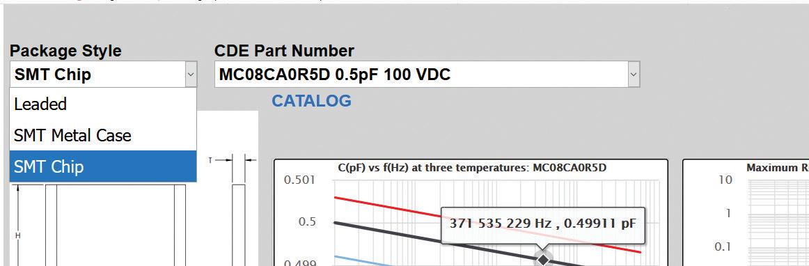
The Package Style selection dropdown in the modeler.
INTERACTIVE CHARTS
The modeler creates six charts for the selected capacitor. A mouse hover over the curve reveals the exact frequency and parameter value. When two or more curves are close to the point of interest, the rectangular border around the displayed coordinates takes on the color of the legend of the series to which you are pointing.
In the left column, the top chart plots the estimated, typical capacitance versus frequency for three temperatures. The nominal capacitance at the applicable test frequency serves as the base capacitance value; and obviously, the device tolerance would be applicable to actual capacitors. The temperature and frequency coefficients assumed by the modeler are typical values but are not warranted.
Below the capacitance chart sits a plot of the typical impedance magnitude and series resistance. At the device’s resonant frequency, the apex of actual impedance magnitude curve will always touch the ESR curve. Note that the limited number of data points in the modeler plot for high-Q mica capacitors means this contact point will sometimes not be precisely resolved.
The bottom-left chart is a plot of the capacitor Q, which is the ratio of the reactance to the resistance. Q is the multiplicative inverse of D, the dissipation factor, which can be visualized from the logarithmic Q chart by mentally reflecting it about the horizontal line with the ordinate value of Q=D=1.

The modeler creates six charts for the selected capacitor. These charts are for an SMT chip device.
In the right column, the top plot graphs an estimate of the maximum expected RMS current handling at three ambient temperatures, assuming the capacitor sits on a typical PCB at the ambient temperature in natural convection. However, we recommend the current be derated and the capacitor be tested under worst-case conditions for qualification purposes.
For package styles other than the SMT metal case, the software calculates RMS current ratings based upon the estimated ESR and at a maximum core heat rise of 60 °C, limited to a 125 °C maximum core temperature when mounted to a PCB in natural, free convection.
For the SMT metal case styles, the maximum RMS current handling calculation assumes a maximum allowable heat rise above ambient of 120 °C and is also limited to a 185 °C maximum core temperature. The default thermal resistance of 50 °C/W is for natural convection without a heatsink or a large heat spreader. The Heatsink Thermal Resistance to Ambient Slider Control can be dragged left to select a much lower heatsink-to-ambient thermal resistance, even as low as 1 °C/W, possible only via an exotic heatsink such as liquid-cooled copper. An aggressive heatsink below 10 °C/W will greatly affect the joule-heating-limited current handling capabilities at higher frequencies. Because of limitations of the current-carrying capacity of the device tabs, the current in all cases is limited to 25 A rms.
The middle chart in the right column is a plot of the real and imaginary components of S-parameter S11, which is identical to S22 due to the capacitor’s assumed symmetric mounting scheme. The final chart in the lower right is a plot of the real and imaginary components of S-parameter S21, which is identical to S12.

Theta slider control for metal-case style chip devices.
For the metal-case style only, a slider tool immediately above the current ratings chart helps specify a value of the heatsink’s thermal resistance to ambient, as these capacitors are intended for heatsink attachment or to be soldered on a copper heat spreader.
The lower frequency span is chosen to cover the frequency at which the capacitance and ESR limits are tested, 1 kHz for capacitors rated 1,000 pF and above and 1 MHz for capacitors rated less than 1,000 pF. Sometimes capacitors rated as low as 10 pF are used at frequencies below 1 MHz, so the lowest plotted frequency is 100 kHz instead of 1 MHz in the range of 10 to 999 pF.
The upper-frequency range is chosen to cover the lower of 6 GHz and a small integer multiple of the first resonant frequency. The multiple is limited by the electrical size of the capacitor as well as the possibility of circulating currents caused by an imbalance of the conductor geometry within the capacitor. Note that above the maximum plotted frequency, there may be notches in the impedance magnitude and upward spikes in the series resistance caused by internally circulating currents. For CDE leaded mica capacitors, part numbers beginning with CMR will generally have better performance in this regard. And Cornell Dubilier’s mica design engineering department may be able to create a higher-performance capacitor to more effectively address special cases.
Site users can generate an output of the model as a frequency listing with Z-parameter or S-parameter values. First select the desired output format in the “Output Format” dropdown box, including the capacitor core temperature. Then click the Generate Model Output button. Note the output format in the popup window will be in space-delimited Touchstone format per the version 1.0 standard. The S-parameter output is 2-port .s2p with a reference impedance of 50 Ω. For the Z-parameters, the format still complies with the Touchstone 1.0 standard but is single-port with the reference impedance set to 1 Ω, so the resistance and reactance in ohms are listed without the need to apply a factor of 50.
The data listing appears in a popup window. The window itself does not by default store to your hard drive or cloud storage path. Probably the best way to store it as a text or .s2p file is simply copy text from the window and paste it into a text editor for import into an RF modeler, plotting in a spreadsheet, etc. The data is the same as that visible in the corresponding modeler charts, reflecting a logarithmic frequency spacing of 100 points per decade, which is a 2.4% pointto-point frequency increment.

Users who generate an output of the model as a listing of Z- or S-parameter values do so by selecting the desired output format in the “Output Format” drop-down box at left, including the capacitor core temperature, then clicking the Generate Model Output button.
This RF modeler is based on mathematical models of the physical construction of the capacitors, crosschecked with a limited amount of roomtemperature vector network analyzer data. Also, note there is little or no conservatism built into the applet. The typical ESR is not a maximum ESR limit, and the maximum rms current is not a warranted life-test condition. And the applet is only valid for Cornell Dubilier capacitors, as their construction and qualities are unique. It’s best to verify performance and discuss application requirements, such as minimum lifetime, with RF Mica application engineers.
Finally, here’s a legal disclaimer: The CDE RF Mica Capacitor Modeler is not a contract, license, or authorization of any kind. Specifications and model are subject to change without notice. Cornell Dubilier assumes no liability on accuracy, completeness or suitability for any application.
REFERENCES: The Modeler, no registration required: www.cde.com/rfmicamodeler/ MicaModeler01.html
CDE Mica Capacitors: http://cde.com/ capacitors/mica


