
6 minute read
Polymer capacitors show promise as MLCC alternatives


Randall Scasny | element14
It pays to know how different capacitor technologies behave when shortages force a search for good substitutes.
The demand for MLCCs (multilayer ceramic capacitors) has outstripped supplies since 2017. Industry observers expect the shortage will dissipate by 2020, but product manufacturers remain concerned. In a quest to find suitable alternatives, an online community of over 650,000 engineers held a spirited design contest which involved testing how polymer capacitors stack up against their ceramic counterparts.
The rise of mobility – both in mobile computing and automotive uses – has triggered enormous demand for MLCCs. The complexity of MLCC manufacturing processes (using alternating nano-layers of ceramic and metal) has limited the number of manufacturers capable of realizing consistent quality control.
The good news is that engineers have a variety of ways to avoid MLCCs in their designs. One approach is to use a larger capacitance in an available package, as long as it doesn’t incur much board redesign. Another approach is to use lesser-valued capacitors in parallel, or use a different capacitor technology altogether, such as conductive polymer capacitors.
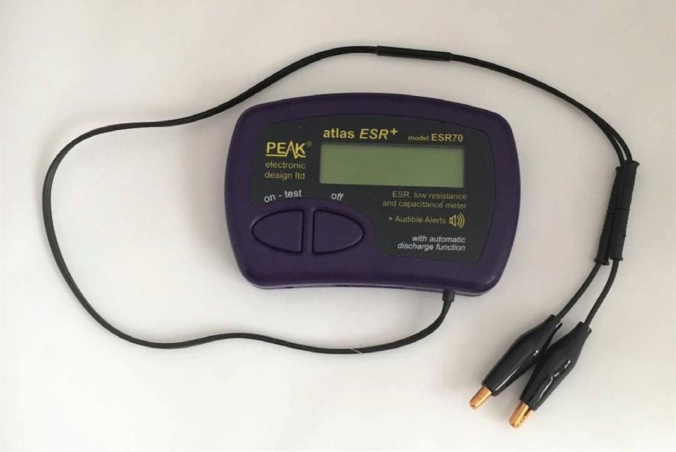
The ESR 70 and ESR meter and Tenma 72-1020 bench multimeter as used to gauge ESR in the capacitor tests.
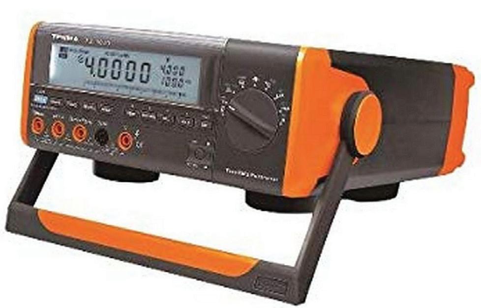
The ESR 70 and ESR meter and Tenma 72-1020 bench multimeter as used to gauge ESR in the capacitor tests.
The element14 online community tested the last alternative through its Experimenting with Polymer Capacitors design contest. There were interesting results.
Design challenge entrants received a kit of 17 types of Panasonic polymer capacitors ranging from 4.7 µF to 470 µF. They also got a peak ESR capacitor tester that made it possible to experiment with different capacitors, build original circuits, modify existing ones, and so forth. Entrants blogged about their findings.
Their first chore was to find the best way to measure Equivalent Series Resistance (ESR) and the actual capacitance of electrolytic capacitors. These parameters are important because today’s microprocessor-based systems require power sources that deliver high current and ultra-fast transient performance, with tight regulation. These conditions create a need for economical, compact capacitors with high capacitance values.
An ideal capacitor has no series resistance, but ESR exists in all real-world capacitors, albeit with small values. Capacitor ESR influences circuit behavior and can worsen over time due to age (e.g. drying out of electrolyte in some capacitors), abuse, and overheating. Power dissipation rises, triggering a vicious circle of continued deteriorating performance.
One of the first experiments members undertook was finding the most reliable way to measure the ESR of polymer capacitors. Members used two different methods, an oscilloscope and an ESR meter, to measure the relative ESR for Panasonic polymer capacitors. The caps met their datasheet specifications for the conditions examined. Members took extra care with lead placement and contact when measuring ESR.
The result: Both methods gave similar results though there were some significant points to note. Capacitance measurements between the ESR 70 and a Tenma 72-1020 bench multimeter were in good agreement although the ESR 70 consistently measured lower than the Tenma 72-1020. The Peak ESR 70 proved easy to use but lacks sufficient accuracy and precision for measuring ESR below about 0.04 Ω.
The oscilloscope method, while more difficult to set up and slower, produced results resembling those of the ESR 70. However, the oscilloscope method has some benefits. For example, by varying the frequency or just observing the shape of the trace, it is possible to get further insight into other non-ideal behavior of the capacitor (e.g., inductance).
OUTPUT SWITCHING RIPPLE REDUCTION
Another experiment investigated the impact of replacing ceramic capacitors with polymer capacitor technology. Members added bulk capacitance to a TI SWIFT Power Module to see if polymer capacitors facilitated an output switching ripple reduction.
The TPSM84A21 10A SWIFT Power Module is a buck converter which can convert an 8-to-14-Vdc input to a 0.508-to-1.3-Vdc maximum 10-A output. The module has both input and output capacitors built in. External capacitance is not normally needed. However, if the input supply sits more than a few inches from the TPSM84A21, the input pins may need additional bulk capacitance. A typical recommended amount of bulk input capacitance is 47 µF - 100 µF.
Community members tested whether a low-ESR polymer capacitance could help. Extremely low ESR is necessary to reduce ripple voltage amplitude, generally a task for using ceramic capacitors. An alternative is a single Panasonic aluminum polymer capacitor which can replace several ceramic capacitors.
Community members evaluated a limited number of conditions at relatively low output power conditions. The first test employed no external bulk capacitance, resulting in about 8 mV of ripple. Switching ripple noise arose at the same frequency as the switching frequency of the module.
Charge pump results. Polymer capacitors can perform dramatically better than MLCC Capacitors, especially when the working voltage is near the rated voltage of the capacitor.
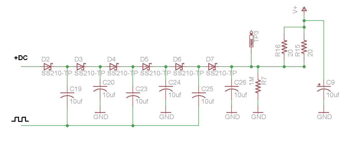
In the case of the design contest, the charge pump circuit was a Dickson design that used a 12-V input. The output of the charge pump was ~48 V with no load.
Members next experimented by adding external bulk input capacitance in the form of a surface-mounted 120-µF Panasonic conductive aluminum solid capacitor. Adding the bulk input capacitor reduced the ripple from 8 mV to 5.6 mV, well below the datasheet value.
Ripple and noise not reduced via filtering may be high enough to degrade the performance of devices connected to the power supply. The addition of bulk capacitance showed how output ripple and output-ripple noise can be reduced.
Another experiment focused on a charge-pump application and compared the performance of polymer capacitors with MLCC capacitors. As a quick review, a charge pump is a kind of dc/dc converter that uses capacitors to raise or lower voltage. Some form of switching device controls the connection of a supply voltage across a load through the capacitor. In charge pumps with a two-stage cycle, a capacitor first connects across the supply and charges to the supply voltage. In the second stage the circuit is reconfigured, so the capacitor is in series with the supply and the load. This makes the voltage across the load equal to the sum of the original supply and the capacitor voltages. The pulsing nature of the higher voltage switched output is often smoothed by the use of an output capacitor.
Charge pumps can double voltages, triple voltages, halve voltages, and generate arbitrary voltages by quickly alternating between modes, depending on the controller and circuit topology. In the case of the design contest, the charge pump circuit was a Dickson design that used a 12-V input. The output of the charge pump was ~48 V with no load.
Experimenters drove this charge pump with a simple power oscillator. The design generated a pulse output using a 74HC4040D ripple counter, 74AC14 Schmitt trigger inverters, and an LMD18201 H-bridge. The circuit used only one of the outputs from this H-bridge driver because the capacitors are polarized, and the full bridge would reverse polarity. Charge pumps employed MLCC capacitors and polymer capacitors, both 10 µF devices rated for 50 V.
Members found that under no load, both charge pumps generated the same voltage boost; with 12-V input they produced 47-V output. Yet to realize a 49-V out, the MLCC circuit needed two more volts at the input, 13% more input voltage.
For the polymer capacitor charge pump at 49-V output with a glue gun heater load, the input power was 7.94 W and the output power was 6.76 W, providing an efficiency of 85.2%. For the MLCC capacitor charge pump, at 49-V output with a glue gun heater load, the input power was 9.15 W and the output power was 6.82 W, providing an efficiency of 74.5%. Test No. Input Voltage (V) Input Current (A) Output Voltage (V) Output Current (A) Output Load (Ohms) Power Dissipated in Load (Watts) Output Ripple (mV) 1 10.52 0.036 1.005 0 Infinite 0 8 2 10.52 0.046 1.004 0.1 10 0.1 8 Test results
Tests also found the output ripple voltage with the MLCC circuit was about five times higher than that of the polymer capacitor circuit, which could be important if this were used as a power supply. With the same input voltage (12 V) the polymer capacitor circuit generated about six more volts (under load) than the MLCC circuit, about 17% higher.
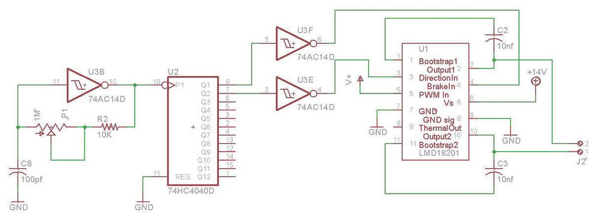
The power oscillator driving the charge pump used only one of the outputs from its LMD18201 H-bridge chip because the capacitors are polarized, and the full bridge would reverse polarity.
A REAL ALTERNATIVE TO MLCCS
The charge pump circuit application showed polymer capacitors can perform dramatically better than MLCC Capacitors, especially when the working voltage is near the rated voltage of the capacitor. These experiments show great promise for polymer capacitors as MLCC replacements. Polymer capacitors, in fact, had advantages over their MLCC alternatives especially in terms of low ESR, less output switching ripple, and better energy efficiency.
The shortage in MLCC capacitors also prompted much discussion in the engineering community regarding passive components in general and the use of conductive polymer capacitors. While supply and demand of MLCCs will eventually stabilize, the current MLCC shortage has helped enhance knowledge of conductive polymer capacitors and how alternatives to MLCCs might avoid supply challenges in the future.
REFERENCES: Evaluating polymer capacitors, https://www.element14.com/ community/community/designchallenges/polymer-capacitors/ blog/2019/05/13/experimenting-withpolymer-capacitors-introductory-blog
The polymer capacitor contest page, https://www.element14.com/ community/community/designchallenges/polymer-capacitors


