
zonal architectures? Why EVs are transitioning to
MICHELLE FROESE • EDITOR
The automotive industry is undergoing a paradigm shift in vehicle design and function, transitioning from traditional distributed to advanced zonal architectures.
By 2030, vehicles with zonal control modules are expected to match those without. Today, some 80 to 90 million cars lack this technology, which will slowly shift closer to a 50/50 split between the two in the next decade.
OEMs are now defining the number of gateways (two, three, or four) required by a vehicle’s central computer and the communication protocols for high-speed data transmission.
But how many gateways are optimal? What type of computer and protocols best meet safety and data needs? And what are the benefits of zonal architecture? Let’s dive in.
What is meant by zonal architecture?
“The zonal architecture is the vehicle’s electrical or electronic, or what we call E/E architecture, that physically
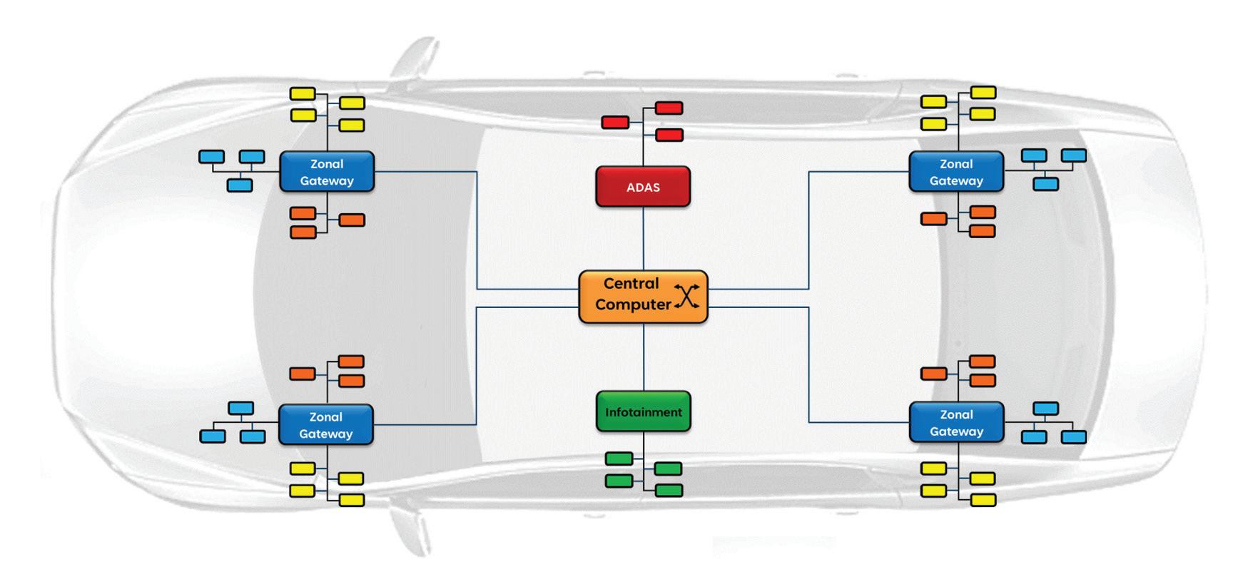
Figure 1. A zonal architecture consolidates functions into specific zones or locations and is controlled by zonal gateways that service many specific functions — such as the ADAS, body, chassis, and infotainment.
consolidates different functions into specific zones within the vehicle,” explains Aaron Barrera, strategic marketing manager with Allegro MicroSystems. “A central computer communicates and controls many of these gateways within an electric vehicle, serving different functions.”
This framework significantly reduces complexity by streamlining communication, power distribution, and system integration, making vehicles more efficient, scalable, and future-ready (Figure 1).
“This is a shift from the earlier distributed architecture, in which several different individual electronic control units, or ECUs, are in the domain architecture,” says Barrera. “In this case, the different functions are typically grouped by domain rather than location.”
Traditional distributed architectures grouped vehicle functions into domains such as body, powertrain, and chassis, each requiring a dedicated ECU. While effective, this system results in numerous ECUs spread throughout a vehicle, leading to a complex web of wiring and power management.
“Now, instead of grouping functions by domain, zonal architectures group systems by location,” Barrera says. “This shift has significant implications for cost, software scalability, and overall vehicle efficiency.”
Zonal architecture organizes a vehicle’s functions by physical location, using centralized computing to manage the gateways within designated zones. Advantages include greater software integration and cost efficiency.
The software-defined vehicle
One of the key drivers behind the adoption of zonal architectures is the softwaredefined vehicle (SDV).
“The software-defined vehicle enables scalability and centralization through a software-based framework — or, as I like to say, a computer on wheels,” says Barrera. “This lets OEMs integrate future technologies and deliver software upgrades without completely redesigning the hardware systems.”
The SDV approach simplifies vehicle design. By clustering multiple functions into
High Voltage Power Inductors

Coilcraft offers a wide range of voltage-rated power inductors that assure the safe, reliable operation of your designs.
Coilcraft voltage-rated inductors support applications such as high-voltage DC-DC and AC-DC power supplies, industrial and home automation controls, appliances, and automotive, including electric vehicles (EVs).
Our XEL and XGL Families of molded power inductors offer operating voltage ratings from 60 V to 120 V, and many of our
LPS and MSS Family inductors are suitable for 400-volt operation or higher.
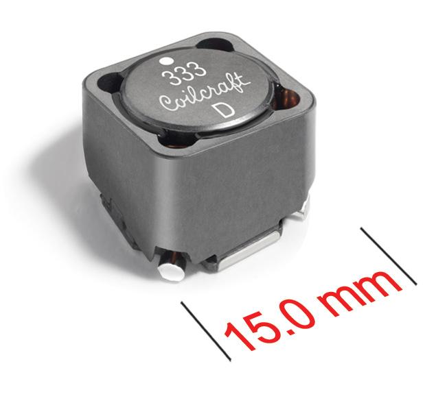
Our new MSS1514V Series offers an 800 V rating in a 15.5 x 15.5 mm footprint, with excellent current handling and low DCR.
Learn more about operating voltage ratings for inductors and see our full line-up at www.coilcraft.com/ HighVoltage.
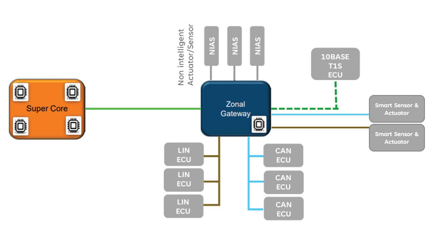
integrated modules, OEMs can reduce the number of ECUs, streamline wiring, and create a less complex framework to maintain and update (Figure 2).
“For example, think about steering, braking, and parking brake systems,” he says. “In a domain-based architecture, these were separate modules. Within zonal architecture, these functions can
be consolidated into a single module. So, rather than talking to three or four separate devices on different boards, why not consolidate this into a single board? Why not have different integrations from an IC or wire harness perspective?”
This consolidation goes beyond hardware efficiency, aligning with the SDV’s need for over-the-air updates
WHEN PRECISION MATTERS.


Figure 2. A central core computer (super core) communicates to many zonal gateways inside the vehicle. The gateways then communicate to many actuators or ECUs optimized for vehicle scalability, efficiency, and long-term cost reduction.
and centralized management. Zonal architectures streamline vehicle management by reducing physical components and enabling software-driven upgrades. They even let OEMs consider new business models and take advantage of subscription-based services.
Most significantly, the “clustering” of ECUs reduces wiring complexity, simplifies management, lowers costs, and creates scalable, adaptable vehicle systems.
Advantages of zonal architectures
The benefits of zonal architecture extend beyond cost savings. Reducing the number of ECUs and wiring required makes vehicles lighter and more efficient, a critical advantage for EVs, as weight directly impacts range and performance.
“If you think about cars today, especially with 12-V systems, many cables run throughout the vehicle. These cables add weight and cost, directly impacting efficiency — particularly in EVs, where lighter cars mean longer battery life. Clustering and simplifying the wiring makes creating a more efficient framework possible.”
What’s more: the centralized nature of zonal architecture enables faster data transmission and real-time communication across the vehicle.

“With a zonal control module, OEMs can optimize communication protocols to handle high-speed data transmission while ensuring safety-critical functions are prioritized,” he says.
Another advantage is the ability to decouple hardware and software development. This enables engineers to innovate and iterate faster, creating more
flexible systems that are easier to scale and update.
“When hardware solutions can reuse the same board or protocols, engineers can simply hook the same wires up, reducing hardware demands and enabling faster development,” he adds.
Zonal architecture also addresses the growing need for cybersecurity and firmware upgrades. By centralizing control, over-the-air (OTA) updates can quickly deliver new features or fixes across all modules. Given the volume of data flowing through modern vehicles, protecting systems from interception or tampering is critical.
“If there’s a system update, a central computer can manage deployment to every module in the vehicle, ensuring customers get access to the latest technology without significant downtime,” explains Barrera. “Higher-end microprocessors and central computers are essential, enabling cybersecurity measures like safe rollbacks, encryption, and firmware authentication. Ultimately, the car must recognize the driver from a hacker, safeguarding against unauthorized access.”
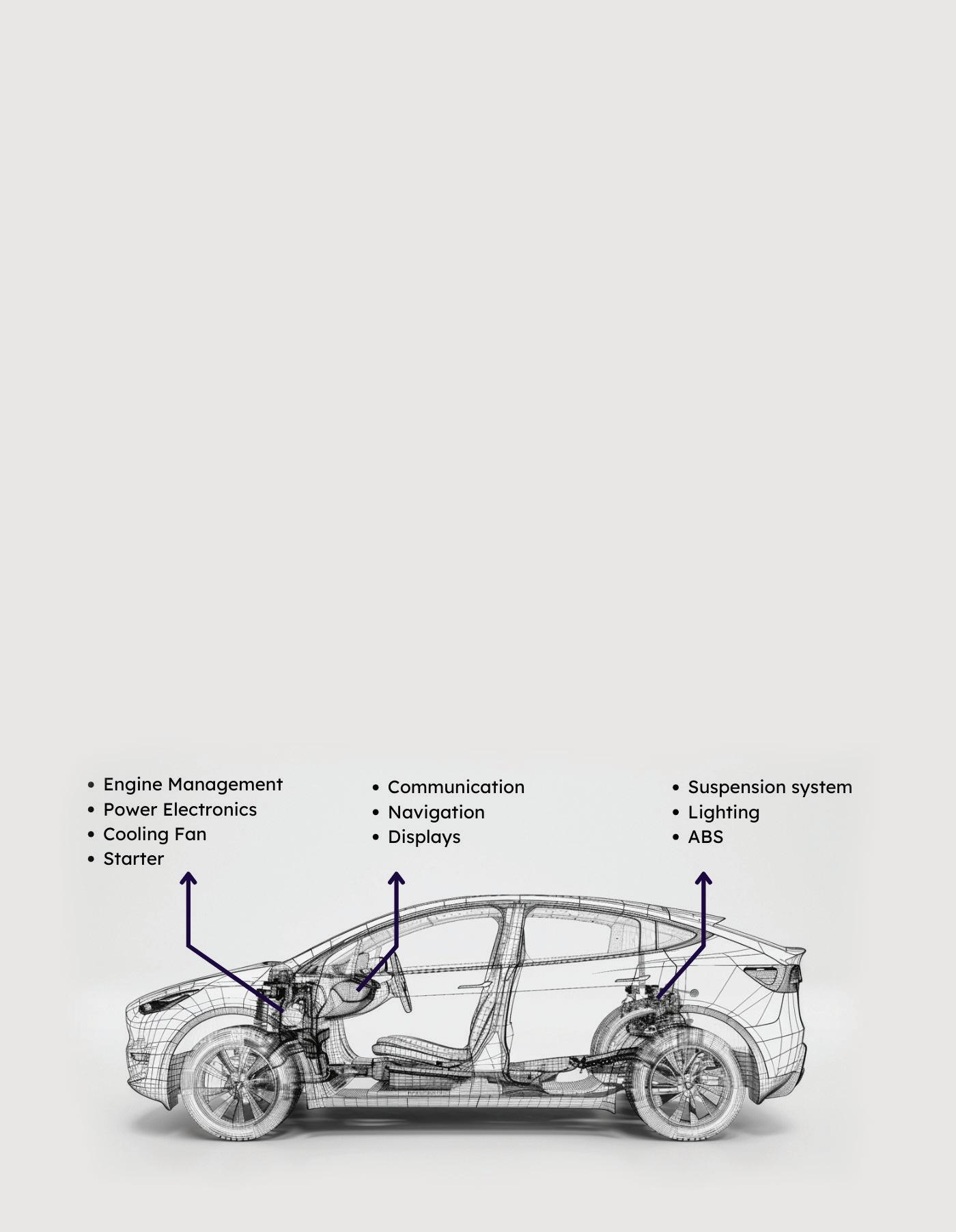
Figure 3. Today’s electric vehicles contain many 12-V loads in the car, but migration to 48-V loads in the future will enable vehicles to have more features, lower weights, and higher efficiency.
The role of 48-volt systems
Zonal architecture also supports the current transition in the automotive industry from traditional 12-volt (V) systems to 48-V ones. The preference for 48-V systems is occurring for several reasons, including power efficiency, weight, and cost savings. Notably, 48-V systems increase power to components without raising the current (Figure 3).
“A 48-V system requires only 25% of the current needed to deliver the same power as a 12-V system, resulting in significant cost and weight savings. Additionally, 48-V systems enable more features and better efficiency, particularly for high-current loads.”
These savings translate into improved vehicle efficiency, as lighter vehicles consume less energy and achieve longer ranges in EVs. Furthermore, lower power dissipation enhances thermal performance, improving reliability and enabling greater system scalability.
While the migration to 48-V systems presents safety challenges, such as higher voltage considerations and increased component costs, advancements in integrated circuits (ICs) and thermal management technologies are providing solutions.
Power distribution is another critical element of zonal vehicle architectures, particularly in managing the coexistence of 48 and 12-V systems. A central component of this process is the Power Distribution Unit (PDU) or Power Distribution Box, which draws voltage from the vehicle battery or an external 48-V supply and converts it for distribution to various zone control modules or gateways.
“There’s a growing need to streamline power distribution across vehicles, especially as we transition to 48-V systems,” Barrera adds. “Efficient power management reduces weight, simplifies wiring, and enhances vehicle performance while supporting high-power applications.”
Power distribution approaches
There are several methods for distributing 48 and 12-V power, each offering unique advantages and drawbacks:
The first approach (Figure 4), 48-V primary distribution with 12-V secondary conversion, involves the PDU sending 48 V to the zone control modules, which then convert it to 12 V for loads requiring lower voltage. This approach provides substantial cost and weight savings
due to thinner, lighter cables for highcurrent 12-V loads while reducing power dissipation. However, the mixed-voltage wire harnesses necessitate stricter safety protocols, and integrating 48-V systems into existing 12-V ECU designs can be highly disruptive.
The second approach, dual 48 and 12-V distribution, sends both voltage levels from the PDU to the zone control modules, allowing greater flexibility to power various loads. This configuration enables direct powering of actuators from the PDU if necessary, offering selective options for either 48 or 12-V loads (Figure 5). However, while this approach provides moderate cost savings, it still requires robust safety measures for mixed-voltage harnesses.
The third approach focuses primarily on 12-V distribution for minimal system disruption while incorporating limited 48-V applications for high-power loads. This strategy requires less redesign for legacy systems, with lower safety demands at the zone control module level (Figure 6). However, it provides fewer opportunities for weight and cost reductions, as the use of 48-V loads is limited.
“Zone control modules play a vital role in managing these mixed-voltage systems,” explains Barrera. “In many 48-V architectures, these modules integrate dcto-dc converters to provide localized 12-V power. They may also consolidate various ECUs and manage a range of loads — including dc motors, stepper motors, resistive loads, and inductive loads.”
Depending on the load requirements, different control topologies — such as high-side drivers, low-side drivers, or H-bridge configurations — are employed to ensure optimal performance and safety.
According to Barrera, manufacturers must consider several key factors to implement mixed-voltage zonal architectures effectively. These include high-current loads (ranging from 10 to 60 amps) and low-current loads (1 to 10 amps), which demand distinct wiring strategies. Of course, safety also remains a top concern, requiring reliable insulation, short-circuit protection and adherence to strict industry standards.
“Transitioning to 48-V systems must balance short-term investment and long-term cost and performance benefits, ensuring scalability for future advancements,” he says. EV

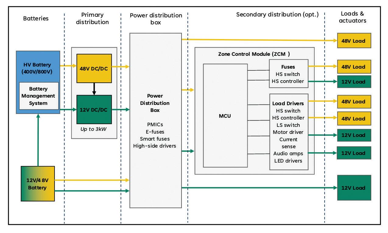
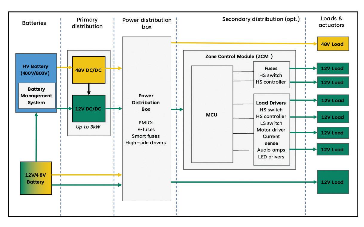
Figure 4. A 48-V primary power distribution with a 12-V secondary power conversion provides high cost and weight savings but higher safety protocols and requires an extensive redesign.
Figure 5. A dual 48/12-V power distribution provides selective flexibility for harnesses and loads with moderate cost savings and safety requirements.
Figure 6. A limited 48-V power distribution has the least amount of redesign for legacy systems but provides fewer opportunities for cost and weight reduction.
What is the automotive open system architecture (AUTOSAR) for EVs?
RAKESH KUMAR PhD CONTRIBUTOR
AUTOSAR (AUTomotive Open System ARchitecture) is a standardized software architecture designed to facilitate the development and integration of software in automotive electronic control units. AUTOSAR plays a vital role in supporting the integration of vehicle-specific features and functionalities.
Why do we need AUTOSAR?
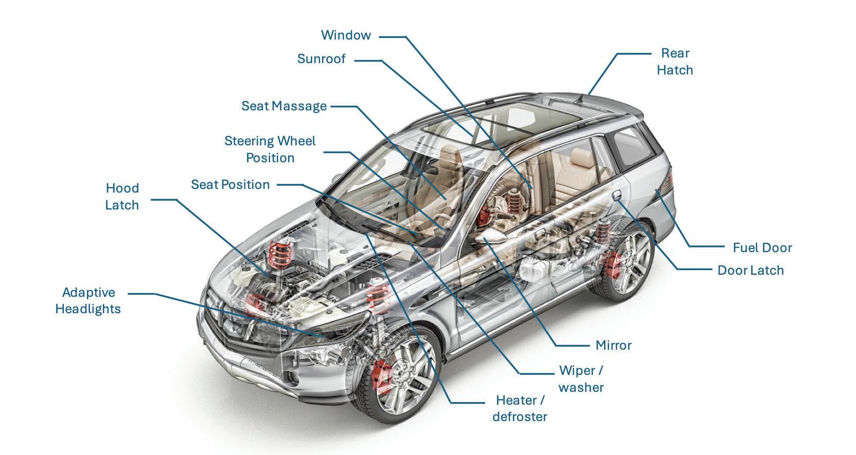
To answer the question, let’s first review how an electric vehicle (EV) network’s components interact in an electronic system. Figure 1 shows the various sensors and actuators connected in an EV.
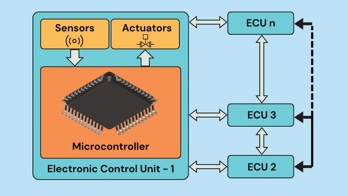
Each sensor and actuator is connected to a microcontroller and collectively forms an electronic control unit (ECU). The number of ECUs corresponds to an EV’s
sensors and actuators. Additionally, all of the ECUs must communicate with one other for the proper functioning of the vehicle.
The data from one ECU is helpful for the other ECU, which leads to complex electronic machinery inside an EV. Figure 2 illustrates the same principle where several ECUs are networked to each other.
The microcontroller is the core of an ECU, and it can be programmed and reprogrammed to perform various functions. In an institution’s R&D sector, ECUs are trained for a specific application within an EV.
Over the years, a specific ECU becomes a reliable architecture that several OEMs can bank upon. However, this is where it can become a problem.
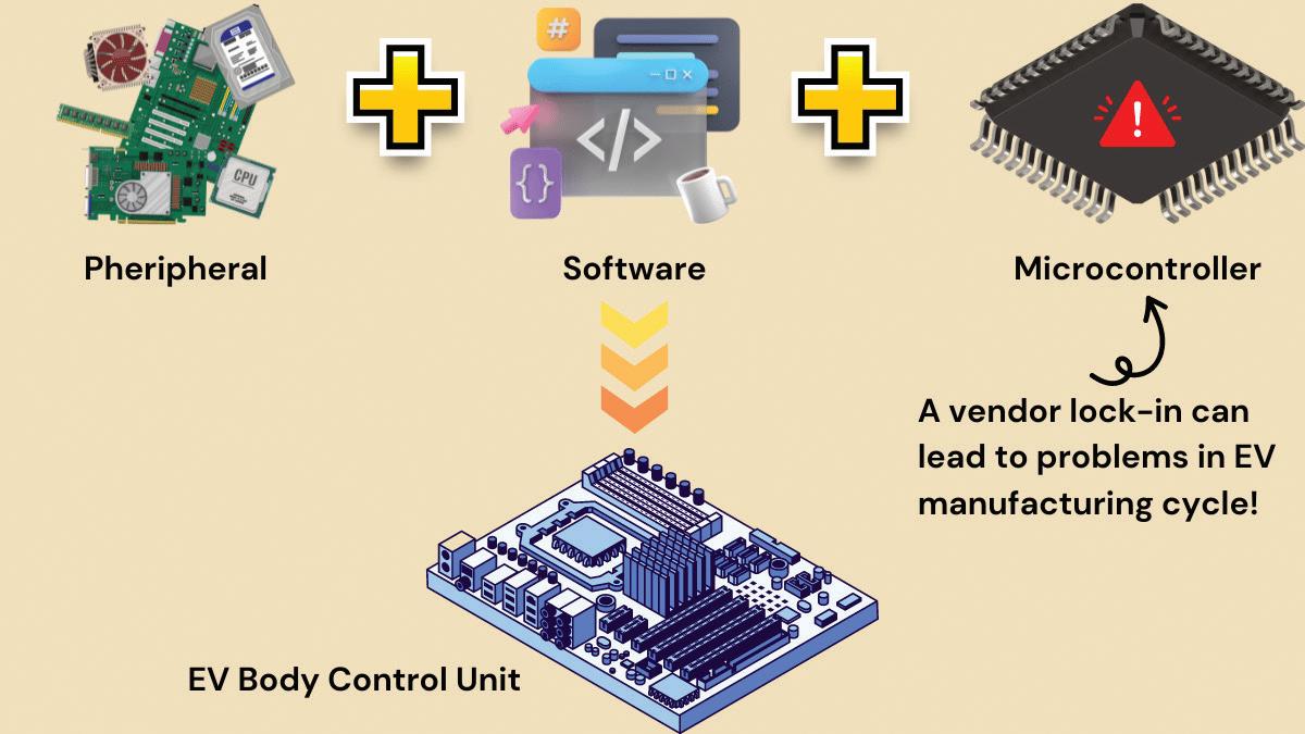
The matured ECU will possess a proprietary microcontroller from a dedicated manufacturer, which means that the continued success of the ECU also depends on the proprietary microcontroller. This leads to a serious reliability risk in EV manufacturing as any unfavorable conditions — such as price rise or stock unavailability — can also adversely affect EV manufacturing.
When switching to a new microcontroller from a different manufacturer, the ECU must be built from scratch. This is because the new microcontroller will have a different architecture.
Figure 3 shows the underlying problem. The microcontrollers could pose a vendor lock-in problem even though the
Figure 1. The various sensors and actuators in an EV.
EV ENGINEERING
peripherals and software might be open source.
EV OEMs recognized this problem and constituted AUTOSAR in 2003 to develop a common platform for building ECUs. These ECUs were not locked to any particular vendor so that EV manufacturing could grow smoothly.
What are the different architectures in AUTOSAR?
The AUTOSAR architectures are classified into three layers:
• Basic Software (BSW) Layer
• Runtime Environment
• Application Layer
Figure 4 shows the three layers arranged one over the other. The microcontroller is at the base of these layers below the BSW Layer.
The BSW Layer has different functions as set by AUTOSAR. Its primary function is to perform as an operating system for the ECU. In addition, BSW communicates via established protocols such as CAN, LIN, or ethernet. It also has access to all input and output ports and handles system diagnostics.
The BSW layer has four inner layers: the Microcontroller Abstraction Layer, the ECU Abstraction Layer, the Service Layer, and the Complex Drives Layer. Let’s review each one.
Microcontroller Abstraction Layer
Popularly called MCAL, this layer is directly connected to the microcontrollers
and forms the bottom layer of BSW. Its task is to make the higher software layers work independently of the type of microcontroller used.
The MCAL functions as an API between the microcontroller and the rest of the top layers. It’s more relevant to the semiconductor manufacturing industry because the microcontroller at the bottom
Figure 2. Components in an ECU and their arrangement.
Figure 3. The components for building an EV body control unit.
can be configured using information from MCAL.
This layer combines the controller drivers, memory drivers, crypto drivers, wireless communication drivers, communication drivers, and I/O drivers.
ECU Abstraction Layer
The ECU Abstraction Layer allows access to the software in the other ECU’s Application Layer. This means that a particular software is not bound to a specific ECU and that not all the software needs to be present in the Application Layer of each ECU.
The higher layers can easily access the drivers present in the MCAL via the ECU Abstraction Layer. This layer hosts the various drivers meant for external devices. It is good to know that this layer keeps the higher layers independent of the ECU hardware layout.
The functions of the ECU Abstraction Layer are:
• Onboard device abstraction
• Memory hardware abstraction
• Crypto hardware abstraction
• Wireless communication hardware abstraction
• Communication hardware abstraction
• I/O hardware abstraction
Complex Drivers Layer
Not a native layer of the original AUTOSAR architecture, the Complex Drivers Layer is meant for functionalities that are outside the purview of the other BSW layers.
The fact that this layer has a direct connection between the microcontroller and the Runtime Environment Layer shows that it can bypass the BSW Layer if necessary.
Service Layer
The Service Layer is the highest of the BSW Layer and houses the operating system of the ECU. It performs various non-volatile memory services and diagnostic services.
The Service Layer governs the various states and mode management of the ECU. This layer provides the communication service to network the different contact points within the vehicle. The Service Layer takes care of the system services, memory services, crypto services, off-board communication services, and communication services. Run Time Environment
The Run Time Environment (RTE) layer connects the Application and BSW Layers as a data and signal exchange medium. It also plays a similar role by connecting the different software components within the Application Layer of a specific ECU without passing through the ECU Abstraction Layer.
However, when the software components in the Application Layer of other ECUs are to be contacted, the RTE layer will ping the BSW layer and use the ECU Abstraction Layer.
One of the key advantages of the RTE layer is its ability to offer flexibility in programming the ECUs, thereby preventing any one-time program locking and empowering the developers.
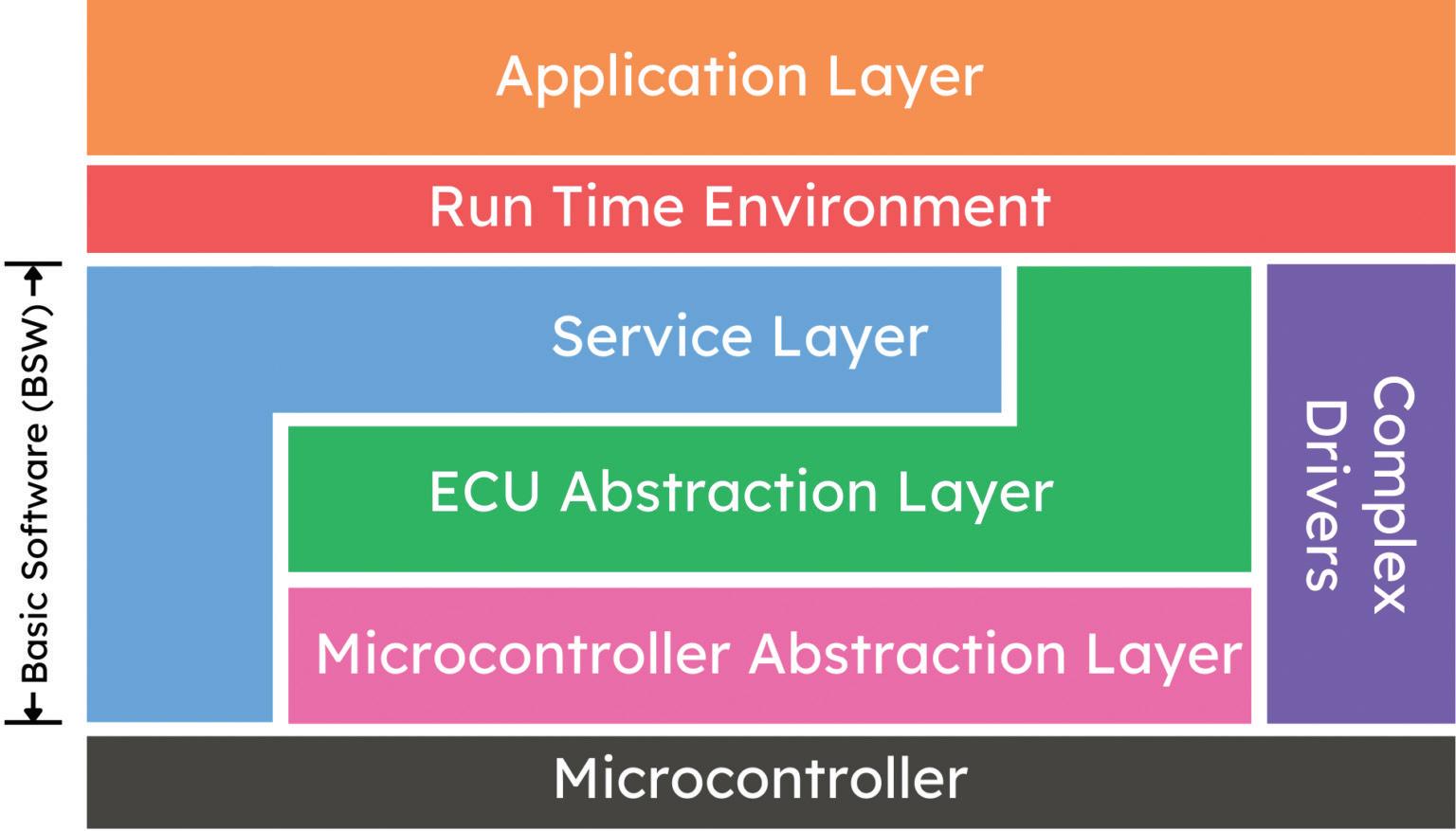
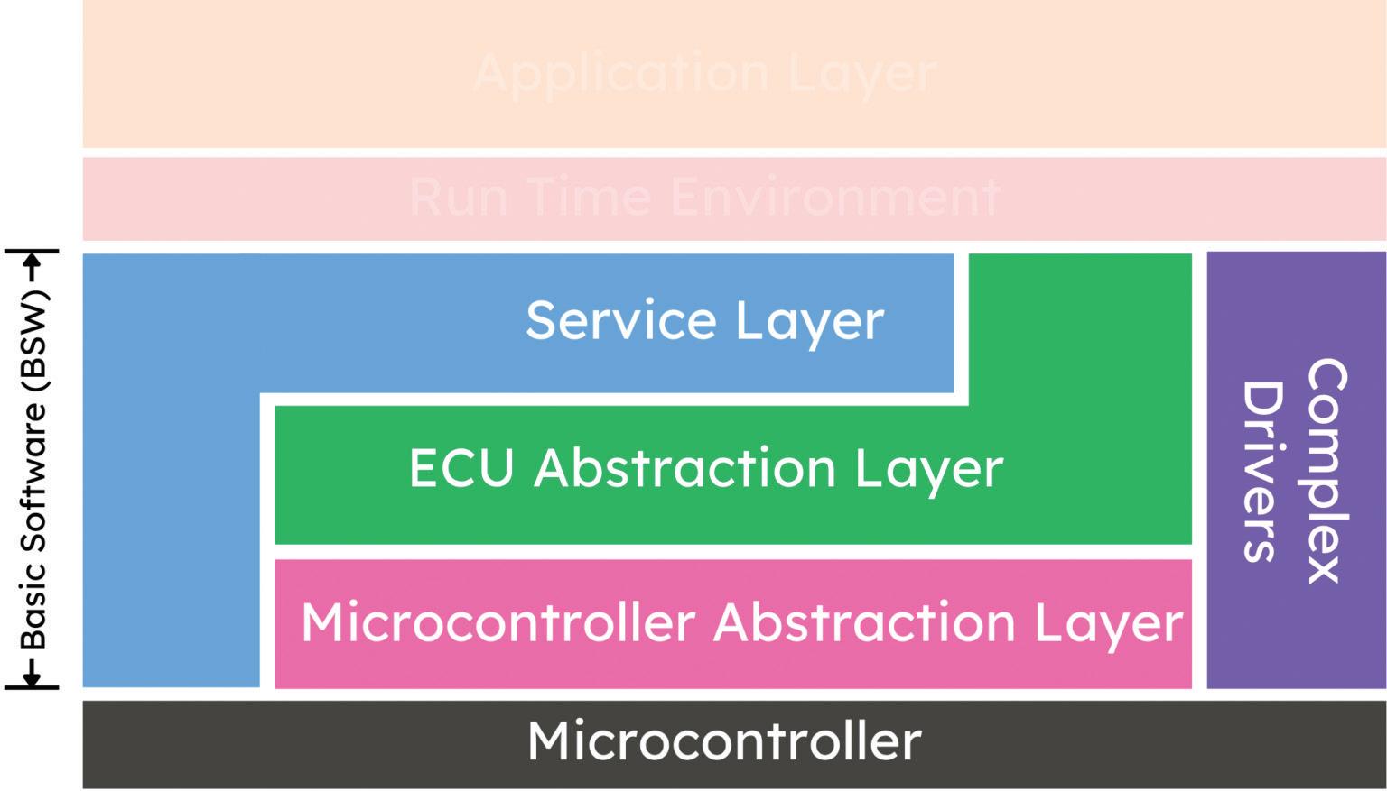
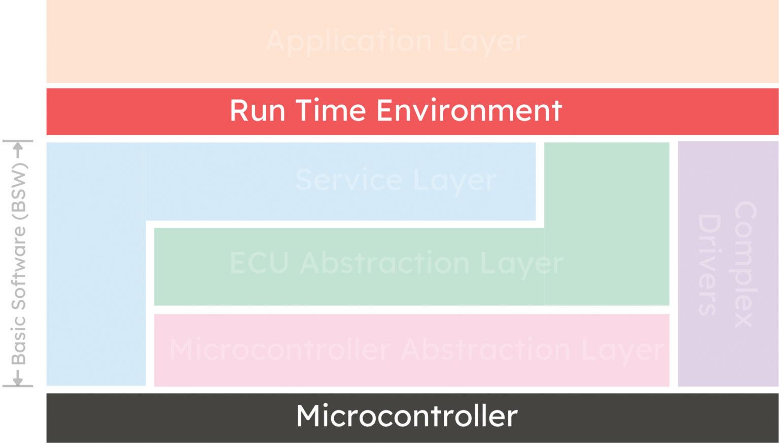

Figure 4. The different layers in the AUTOSAR architecture.
Figure 6. The Run Time Environment layer in the AUTOSAR architecture.
Figure 5. The BSW Layer in the AUTOSAR architecture.
Figure 7. The Application Layer in the AUTOSAR architecture.
Application Layer
Application Layer is the layer for which many OEMs pay and buy the ECU itself. This layer houses the different software components and can change from one ECU to another.
This layer often specializes in a specific application, such as a door lock or airbag mechanism. Heavy research is focused on making this layer robust, and it is fast developing into a lucrative career in EV engineering.
Even though this layer calls for software specialization, another ECU can also use the software component of an Application Layer. For this matter, the communication has to pass to the ECU Abstraction Layer of all the ECUs concerned.
Summary
AUTOSAR is not just a standard protocol but an exciting career opportunity for those aspiring to become EV engineers. This protocol is meant to break any vendor lock-in mechanism, which means that the scope of AUTOSAR spans a wide variety of EV markets. EV

Coilcraft’s MSS1514V high-voltage power inductors are rated at 800 V, doubling the voltage capacity of comparable parts.

Note: All images courtesy of Rakesh Kumar, Ph.D.


DESIGN GUIDES
Key technology content produced by the editors of EE World compiled in individual PDFs. Download your free design guide today!


Find these downloadable technical guides in our DESIGN GUIDE LIBRARY, bookmark this site as guides are added on an ongoing basis!
www.eeworldonline.com/design-guide-library