


starting at $4.00/5 pk. (PLUG532)

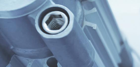
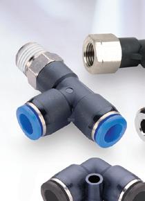
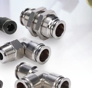
NITRA pneumatic push-to-connect fittings are easily installed and work well with flexible tubing to make sealed connections.
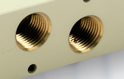
• Threaded connections available with NPT, G-thread, and BSPT R-thread types
• Union-style fittings
• Available in thermoplastic, nickel-plated brass, or stainless steel bodies


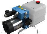
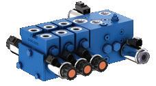
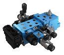
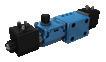
starting at $23.00 (7001000100U)


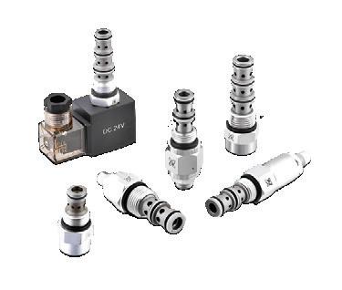
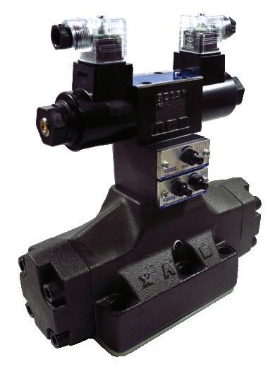
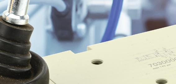
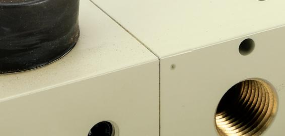
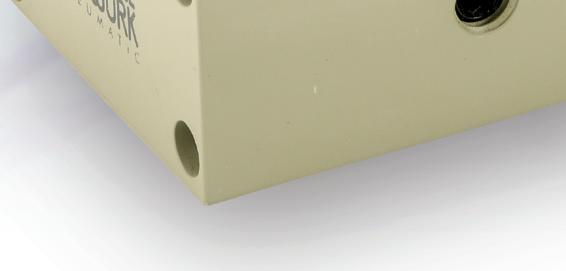
Metal Work is a trusted name in pneumatic components, and we now carry several valve types, including toggle and axial lever manual valves, push-pull manual valves, mechanically operated air valves (mechanical limit switch valves), pushbutton air valves, air pilot valves, and solenoid valves. Configuration and port sizes include 3-port, 3-way, 2-position, and 5-port, 4-way, 2- or 3-position valves.


• Configuration options include male straight (hex and round body), bulkhead female, long male elbow, tee reducers, and much more
• High working pressure and temperature
• Threaded elbow and tee fitting bodies can be rotated after installation
• Coils sold separately for solenoid valves in voltages from 12 VDC to 220 VAC
• Solenoid valves are available in internally and externally piloted versions
• Externally piloted valves allow a comprehensive pressure range and control pressures down to amfull vacuum


starting at $15.50 (CPS9D-AP-A)

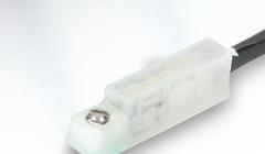
NITRA cylinder position switches are compact purpose-built switches designed to detect the position of a cylinder.

• Electronic solid state switch output
• GMR sensing technology
• LED switch status indication
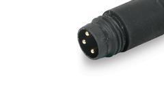
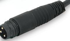
• Integral 0.15m cable with M8 snap-fit connector or 3-meter wire leads
• Come with either 45 or 90 degree cable
• 5-28 VDC operating voltage
• NEMA 6 / IP67 rating
• CE, RoHS, REACH approvals

Mary C. Gannon • Editor-in-Chief
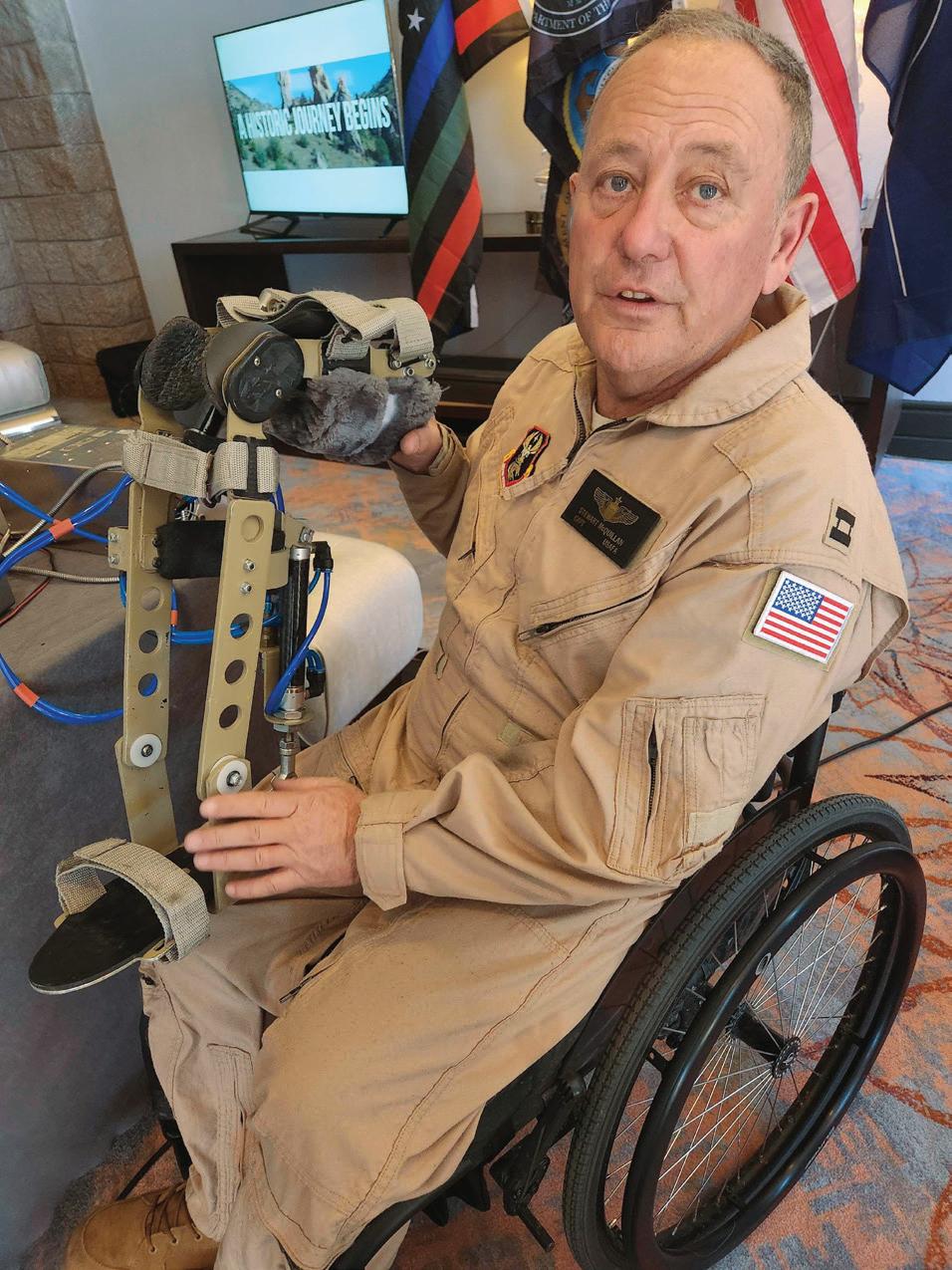
FLUID POWER SAVES LIVES.
That is how Captain Stewart McQuillan addressed the audience at the National Fluid Power Association's annual conference in February. McQuillan, Colonel Sean McClung and Kristen Christy opened the conference to highlight their foundation and introduce the industry to a device he created to allow him to continue flying helicopters despite being paralyzed after an issue with his Royal Air Force fighter jet crushed his spinal cord.
The three are founders of the NV3 Foun dation, which aims to build a fully self-con tained village for veterans with housing and medical facilities. The organization will also teach new hands-on careers or allow vets to restart old ones. It will build a thriving social community of like-minded vets and their families, giving full community support to veterans all day and night.
This idea is modeled after a successful venture in the UK after World War I when veterans returned home ill with tuberculo sis. They gathered them all to recuperate, live together and work in trades. It was hailed as “the most successful social medical experi ment of our time.” The NV3 Foundation was established to give veterans purpose once again and prevent the massive suicide epi demic among the veteran community.
When asked why he said fluid power saves lives, McQuillan, a pilot and electrical engineer, noted that he was one such veteran in a very dark, bleak place after his accident. It wasn't until he started working with other engi neers to design the Aeroleg, an FAA-approved

Mary C. Gannon • Editor-in-Chief mgannon@wtwhmedia.com linkedin.com/in/marygannonramsak


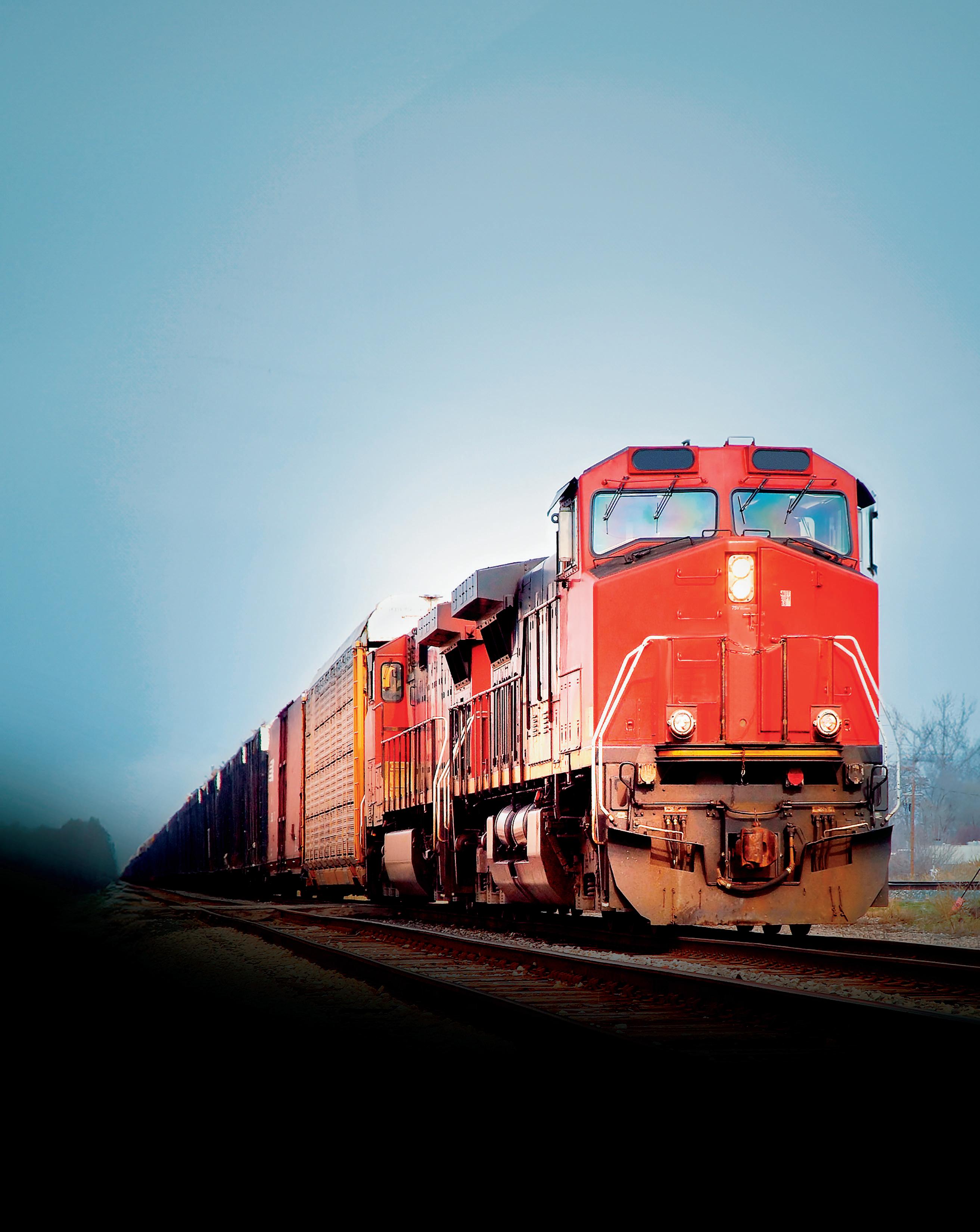
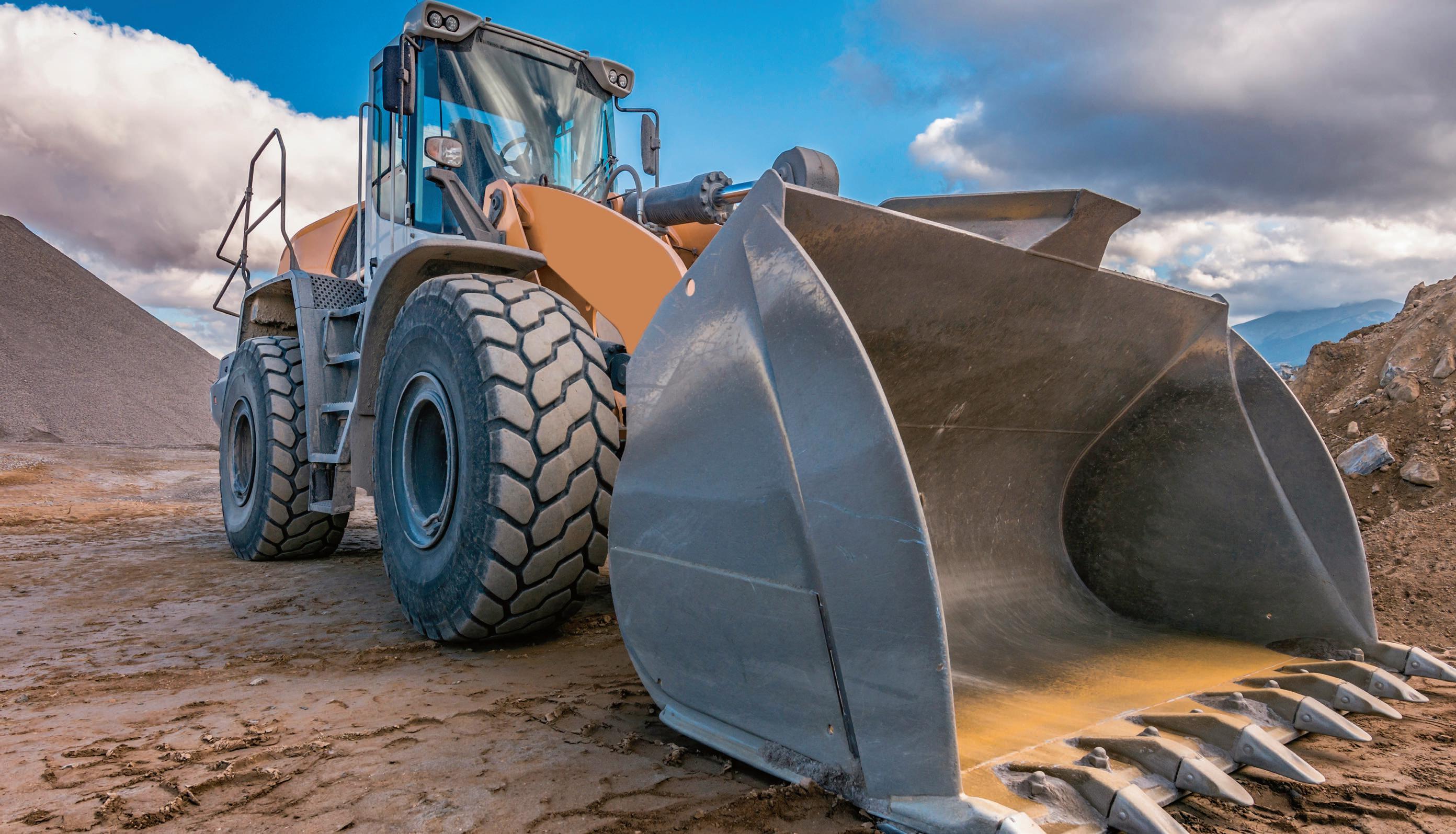
Hydraulics help mobile cranes soar — safely
Hydraulics are predominantly used in most mobile crane designs, from the cylinders for lifting, to valves for holding, and more.
Advanced motion controllers enable one-of-a-kind cold press design
Cold presses using Delta Motion controllers help ensure consistently stronger, more accurate fittings for military vessels.
38 PNEUMATICS
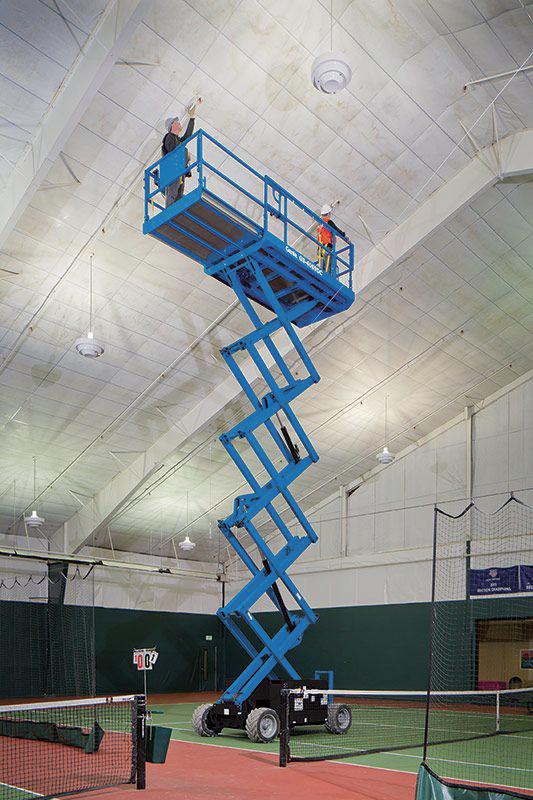
Keeping it clean in food & beverage
Pneumatics technologies offer the clean designs and reliable operation required in food and beverage processing.
43 OTC SHOW PREVIEW
Innovations and sustainability make waves at OTC 2025
Fluid power manufacturers return to the Offshore Technology Conference in Houston May 5-8 to showcase their durable, reliable and powerful designs.


PRODUCTION
VP,
Art
Art
esummers@wtwhmedia.com
Director,
rellis@wtwhmedia.com
Audience
atanner@wtwhmedia.com
PRODUCTION SERVICES
Customer Service Manager
Stephanie Hulett shulett@wtwhmedia.com
Customer Service Representative Tracy Powers tpowers@wtwhmedia.com
Customer Service Representative JoAnn Martin jmartin@wtwhmedia.com

www.nfpa.com


Customer Service Representative Renee Massey-Linston renee@wtwhmedia.com
Customer Service Representative Trinidy Longgood tlonggood@wtwhmedia.com


MARKETING
VP, Operations
Virginia Goulding
vgoulding@wtwhmedia.com @wtwh_virginia
Digital Marketing Manager Taylor Meade tmeade@wtwhmedia.com @wtwh_taylor
SALES
Ryan Ashdown 216-316-6691 rashdown@wtwhmedia.com
Jami Brownlee 224.760.1055 jbrownlee@wtwhmedia.com
Mary Ann Cooke 781.710.4659 mcooke@wtwhmedia.com
Jim Powers 312.925.7793 jpowers@wtwhmedia.com @jpowers_media
Courtney Nagle 440.523.1685 cseel@wtwhmedia.com @wtwh_CSeel
LEADERSHIP
CEO Matt Logan mlogan@wtwhmedia.com
Co-Founders Scott McCafferty Mike Emich


SUBSCRIBER SERVICES: To order a

Rachael Pasini • Senior Editor
WE TAKE BREATHABLE AIR for granted. To practice gratitude, I often ask my now eight-year-old son how long he thinks he can live without food. Up to a month, if he still has access to water. How long without water? Maybe a few days, depending on his activity level and environmental conditions. How about air? Only a few minutes. Then, I get out a stopwatch and tell him to hold his breath. He clocks under a minute and scolds me for making him laugh.
Without reliably clean air, concerns over water and food become moot. The Clean Air Act was implemented to ensure our atmosphere contains safe, breathable air for generations to come. It regulates hazardous air emissions from stationary and mobile sources and holds companies accountable for unlawful actions.
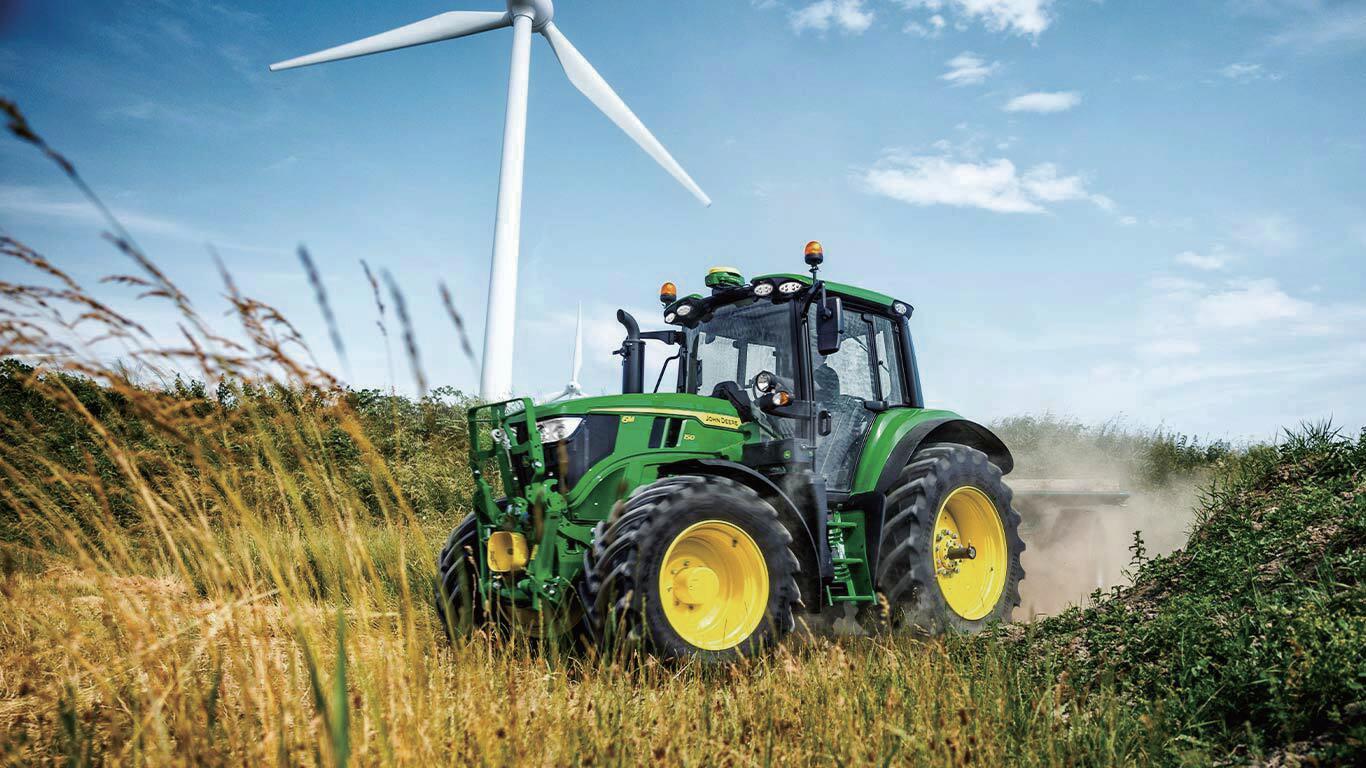
Late last year, the EPA reached a settlement agreement with a crane company that violated Clean Air Act emissions standards and other requirements from 2014 to
2018. The company imported cranes with at least 1,032 noncompliant diesel engines that exhausted nitrogen oxides (nox), groundlevel ozone, and particulate matter along a 70-mile pathway. Now, the company is on the hook for $42.6 million and a we’re-so-sorry project for the surrounding community.
Was it worth it? Did the company do such good business during that time that it can now spare $42.6 million? Did the leaders forget there were laws in place, standards to meet, and protocols to follow?
In this day and age, especially with worldwide net-zero goals and mandates, it’s alarming that any company would overlook regulations and neglect to consider the consequences of not meeting emissions standards. Even with the rollercoaster ride of the current administration, and even if the Clean Air Act ends up upended, any new administration could allow the prosecution of past noncompliance.
(Please take note of my self-restraint as
I don’t snarkily call out a lack of concern for environmental and human health…or perhaps I just did.)
Regardless of personal or political stance, the reality is clear: Violating the Clean Air Act is bad for business. Can you afford a multimillion dollar hit and negative publicity down the road? Or instead, can you spare a few extra minutes now to tweak your designs, collect and report accurate data, and doublecheck that you’re in the clear?
If you’re not sure, get a stopwatch and hold your breath. How long can you last without air? FPW

Rachael Pasini • Senior Editor rpasini@wtwhmedia.com linkedin.com/in/rachaelpasini


Munich, Germany
April 7-13, 2025 Hall A3, Booth 327
Innovation starts with Bosch Rexroth and HydraForce. Our expert application engineers design efficient electro-hydraulic systems, delivering compact hydraulic solutions that enhance machine performance. Whether it’s an upgrade, redesign or new motion control application, rely on our global team to help you gain a competitive edge.

Edited by Mary C. Gannon • Editor-in-Chief
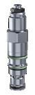
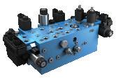
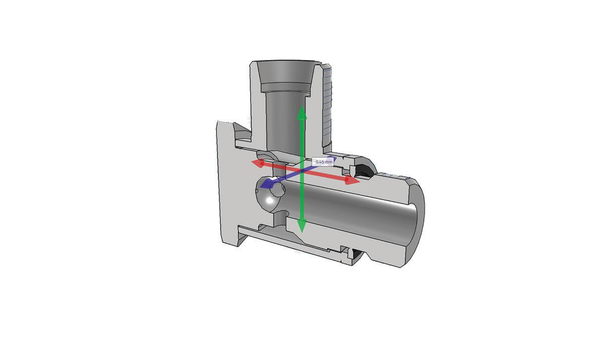
BY: Marcel Stamber-Bur, Development – Industrial Valves,
Thomas Daniel, Application Development – Industrial Valves, Lars Hauptmann, Product Division Marketing, Dr. Nora Nagele, Head of Product Division Marketing – all Hydac Fluidtechnik, GMBH, Sulzbach/Saarland
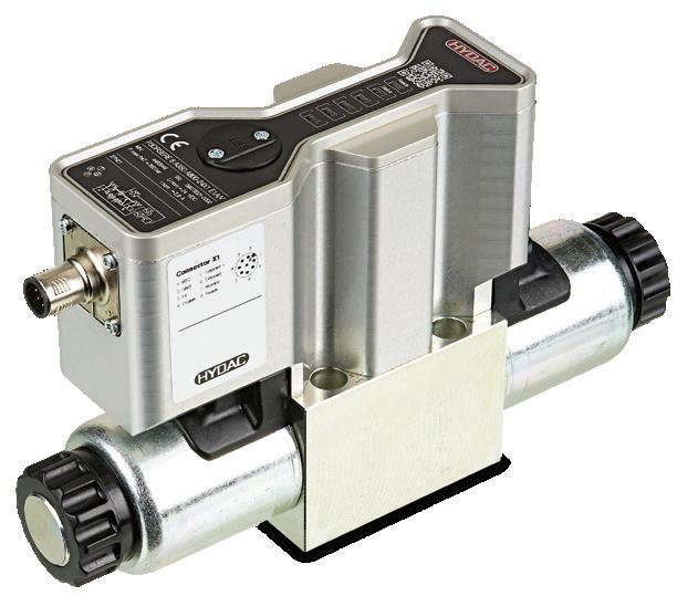
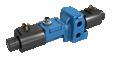
with regards to energy efficiency and quality have increased continuously over recent years. They need to not only set clamping pressures precisely but also retain them over time without loss. Hydac has developed a new solution for this field of application: the new proportional pressure control valve in seat-tight design comes with intelligent closed-loop control and integrated electronics. The seat-tight design ensures that no leakage occurs when the pressure is set and thus lowers energy consumption. The on-board electronics set the required pressure precisely.
Hydraulic systems, such as the clamping hydraulics in machine tools, often use proportional valves for pressure control. In conventional proportional pressure control valves with piston design, internal leakage occurs because of the inherent clearance between piston and hole. As both piston and hole are subject to form and position tolerances because of the production methods used, the amount of clearance cannot simply be reduced: a range of a few micron is necessary. In combination with high pressures, even this small gap results in not inconsiderable leakage flows that make it impossible to maintain the pressure permanently without additional supply. This lost energy must regularly be returned to the system, for example by a pump or an accumulator. This results in higher energy requirements and entails additional challenges, such as higher noise emissions and more space being needed for the components.
One way to reconcile the conflicting objectives of proportional pressure control and
INTELLIGENT
Hydraulic systems, such as the clamping hydraulics in machine tools, often use proportional valves for pressure control.
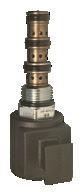
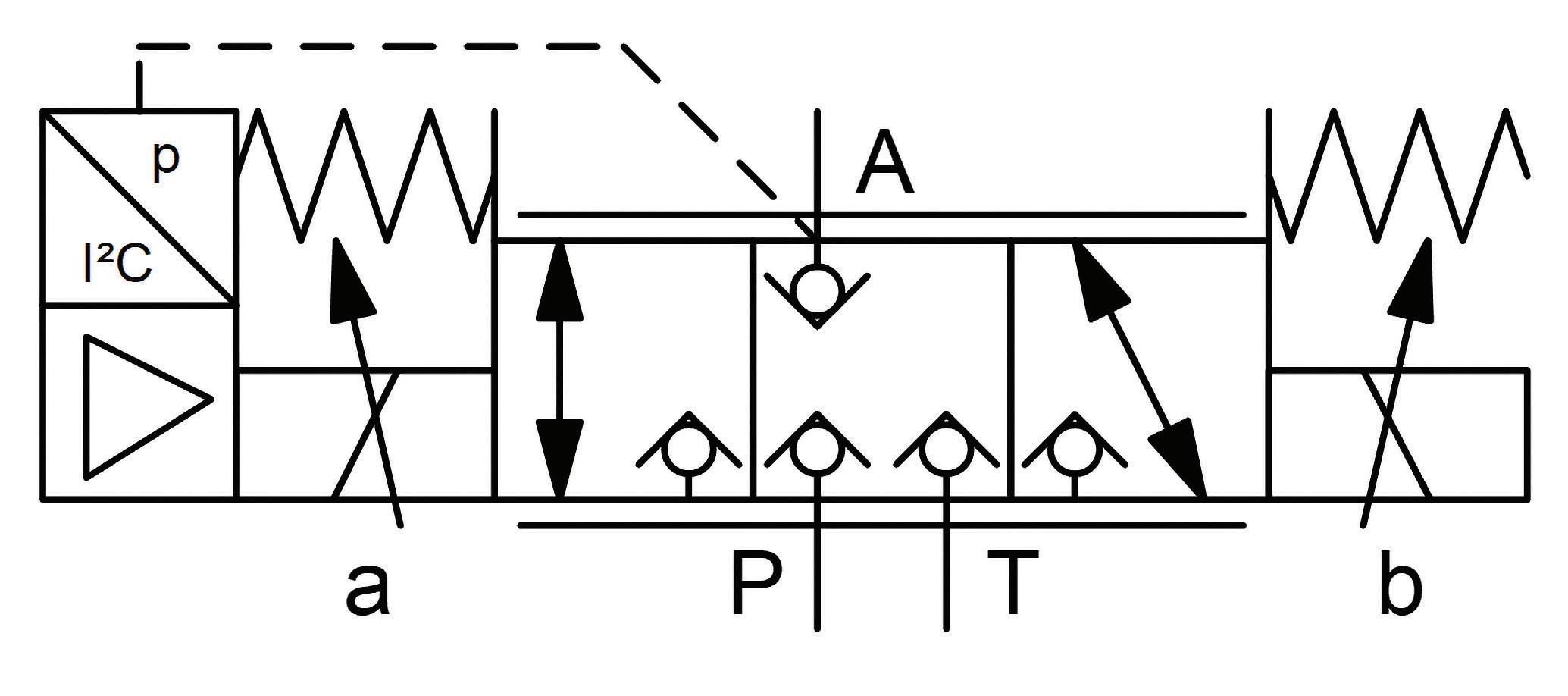
energy efficiency is to use a seat-tight design. This involves a cone being pressed against a seat edge, forming a metal-to-metal seal and eliminating the gap. This design enables the valve to function without any internal leakage. Pressure control valves are a combination of pressure relief valve and pressure reducing valve. To realize this function, three hydraulic
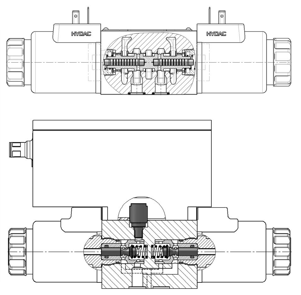
COMPARISON OF CONVENTIONAL VALVES WITH THE HYDAC INNOVATIVE SMART VALVES.
ports are typically needed in the valve (actuator port A, pump P and tank T). In pressurereducing mode, the valve creates a pressure drop from P to A, setting the desired pressure in A. To reduce the actuator pressure, the valve opens the flow path from A to T, thus functioning as a pressure relief valve. Conventionally, this pressure control is realized by a piston that controls the connections from P to A and from A to T. As described earlier, this design results in internal leakage in the valve. A balance of forces between the surfaces of the valve piston that are exposed to pressure and the spring or solenoid forces causes the desired pressure to be set. This also means that the design is limited to a small number of pre-defined pressure ranges, as a different piston diameter needs to be configured for each pressure range.
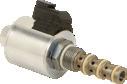
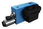
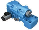
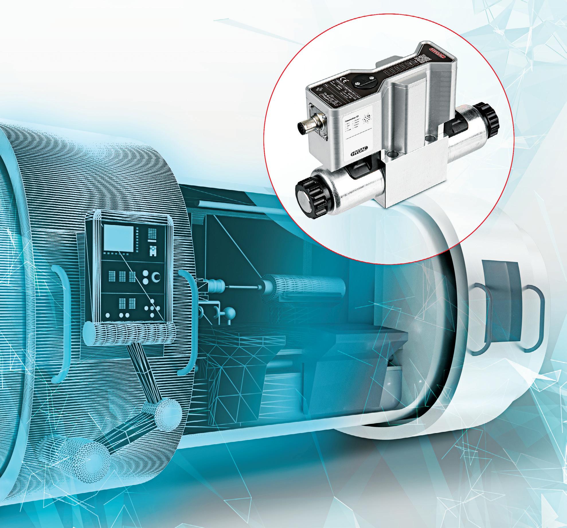
With the P3DRSERE 6, Hydac has realized a pressure control valve with decoupled control edges in poppet design. The actuator pressure is measured by an internal sensor and compared with a nominal value by on-board electronics.
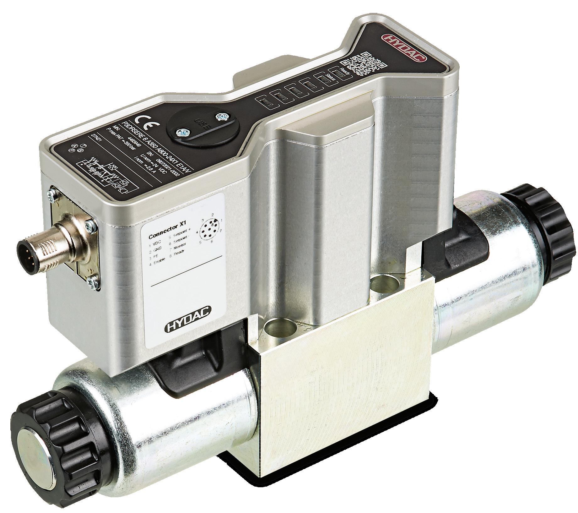


With the P3DRSERE 6, Hydac has realized a pressure control valve with decoupled control edges in poppet design.

control edges are closed and the set pressure is maintained without leaks. This happens even in the event of an error, e.g. power supply failure or cable break. In a machine tool, for example, this means that the workpiece will remain clamped safely in place if an error occurs.
As standard, Hydac supplies the valve with three controller pre-settings (slow, medium, fast). As the pressure control is highly dependent of the specific application, the customer is able to adjust the controller parameters. Software has been developed especially for this valve with a graphic interface that enables individual adjustments to be made to suit the application. For instance, the pressure rating can be defined


Mary C. Gannon • Editor-in-Chief
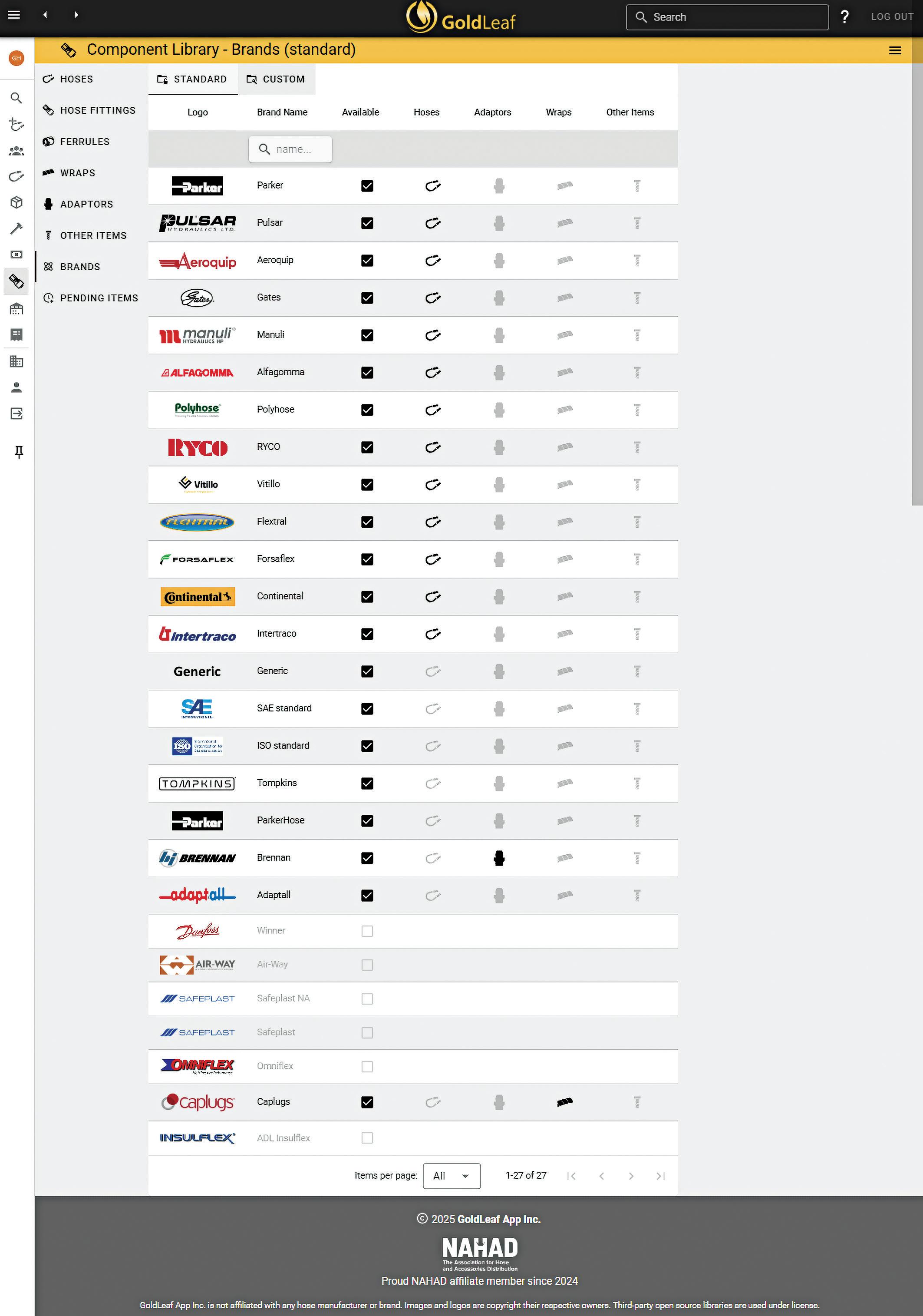
specifying, designing and selling multiple assemblies can be a time-consuming task, as one must review multiple pieces of data before creating a full order. But a new software program, the Goldleaf App, promises to transform the way distributors and OEMs manage, configure, and quote their hydraulic hose assemblies. The app provides a seamless experience for technicians and engineers tasked with navigating multiple catalogs and website pages, reducing errors and improving operational efficiency.
Created by a mechanical engineer with years of experience in machine design and hydraulic hose distribution, Goldleaf is the culmination of over a decade of industry knowledge, handson expertise, and a drive to innovate beyond the traditional tools and processes that have defined the hydraulic hose sector for decades.
Grant Holohan, P.Eng., President, GoldLeaf App Inc., began his career in mechanical engineering, focusing on machine design for industrial and mining equipment. After time living overseas, he wanted a career that was more hands-on, so he transitioned into the hydraulic hose distribution business. Joining a company now known as Multiflow Solutions, he initially worked as an engineering manager before expanding his role to include business development. It was there he saw the confusion and complexity of specifying hose assemblies across multiple brands, sizes and fittings.
“I remember having to flip through three different catalogs just to configure and assemble a single hose,” he recalled. “I’d have to crossreference specifications from one, compatibility details from another, and then crimp specs from a third catalog. It was unnecessarily complicated and time-consuming. I kept thinking: Why isn’t there an easier way?”
This drove him to work with management
to build a tool to simplify the process. The initial prototype proved invaluable for his team at Multiflow and served as a stepping stone to Goldleaf. After several years there, Holohan felt the call to try something new so decided to take the idea he’d created for one distributor and hone it into a more encompassing product that went farther than most ERP tools currently available.
Using modern software technologies, he built Goldleaf and launched in June 2023. Goldleaf is a web-based platform designed to simplify and standardize the hose specification and assembly process. It addresses critical pain points in two major market segments: OEMs with high-volume, repetitive hose configurations, and counter repair services that handle diverse and unique requests.
The tool’s standout feature is its ability to centralize and streamline data management. This means taking a list of hose requirements — whether they come in a spreadsheet, email, or even scribbled on a napkin — and turning it into
“Goldleaf takes all that guesswork out of the equation, giving users confidence that they’re configuring hoses correctly every time.”
a structured, repeatable system. For repair services, it ensures new team members can spec and assemble hoses with the same accuracy and consistency as seasoned experts.
“Hose distributors often rely on one or two key people who know everything — compatibility, stock levels, crimping specs — and when those people are unavailable or leave, it creates a bottleneck,” Holohan said. “Goldleaf eliminates that bottleneck by storing all that knowledge in one accessible system.”
The app includes all pertinent data, such as hose brands, sizes, fittings and adapters. It also allows you to include items like hose sleeves and wraps, hose burst testing data and proper saw data. You can also create bills of material, data sheets and price breakdowns.
Key features include:
• Customizable product libraries: Goldleaf allows distributors to define their specific product offerings, stock levels, and pricing structures. This ensures users can select from pre-approved materials, minimizing the risk of quoting or configuring items they don’t actually carry.
• Integrated pricing and quoting tools: Whether users price assemblies based on costplus-margin, list prices with discounts, or other methods, Goldleaf supports detailed and customizable pricing models. It even accounts for labor costs and scrap rates, providing a comprehensive and accurate quote for customers.
• Automated data sheet generation: With the click of a button, users can generate professional, PDF-formatted data sheets for their customers — complete with all the critical specifications and details for each hose assembly.
• Cross-brand compatibility checks: Goldleaf simplifies cross-referencing between hose brands, making it easier for distributors to


offer alternative options to customers loyal to specific manufacturers.
• ERP integration: The tool integrates with enterprise resource planning (erp) systems, such as Profit 21 by Epicor, enabling seamless data flow between Goldleaf and other business management systems.
Unlike older systems that often require multiple disconnected tools or clunky spreadsheets, Goldleaf is fully web-based and accessible from any device with an internet connection. There’s no need for software installations or cumbersome updates — everything runs smoothly through a browser.
The user interface is designed with practicality and efficiency in mind. For example, if a user starts specifying a hose configuration and later realizes they need to change the hose size, Goldleaf automatically recalculates the corresponding crimp fittings and cut lengths. This prevents users from having to re-enter data, saving time and reducing frustration.
Additionally, Holohan said, another new feature is the ability to define a hose-assembly by its description. Instead of having to select from a variety of fields, users can type things like, 100R17 1/2 in. hose with FJX and FJX90 ends, 45.3 in. or 797TC-12 with ORFS on each end, 8 ft or even 6 ft 1 in. hose, 6,000 psi with code 62.
From the text description, the app can identify the components and design the hose assembly.
Another highlight is its ability to adapt to onthe-ground needs. Field technicians working on the shop floor can use their phones or tablets to enter part numbers or descriptions into Goldleaf, which then converts these entries into standard parameters used by the distributor. This feature bridges the gap between technical expertise in the field and back-office precision.
“People are often surprised by how much time they waste on simple lookups and crossreferencing,” Holohan said. “Goldleaf takes all that guesswork out of the equation, giving users confidence that they’re configuring hoses
correctly every time.”
Goldleaf is preloaded with catalog data from major hydraulic manufacturers, and its library is continuously updated to reflect the latest products and specifications. The development team also monitors industry updates to ensure customers always have access to current information.
For example, during testing, a Parker distributor flagged a missing hose from the global catalog. The Goldleaf team had it added within a day. Such responsiveness has earned the platform early praise from clients who appreciate its agility and customer-focused development approach.
New features are being added regularly, and the team is already exploring integrations with other ERP systems and expanding brand compatibility options. “There’s a lot we can still do,” Holohan said. “Our goal is to keep refining Goldleaf until it becomes the industry standard for hydraulic hose assembly management.” FPW Goldleaf goldleafapp.com

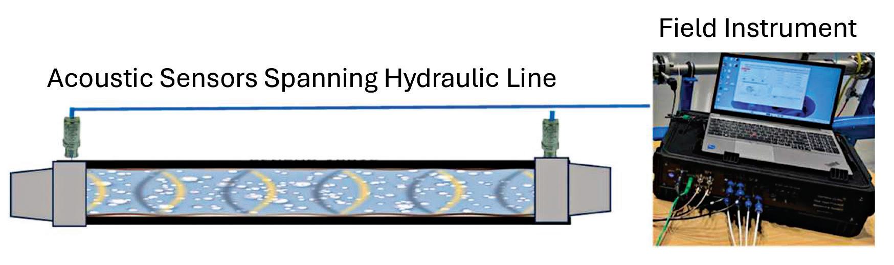
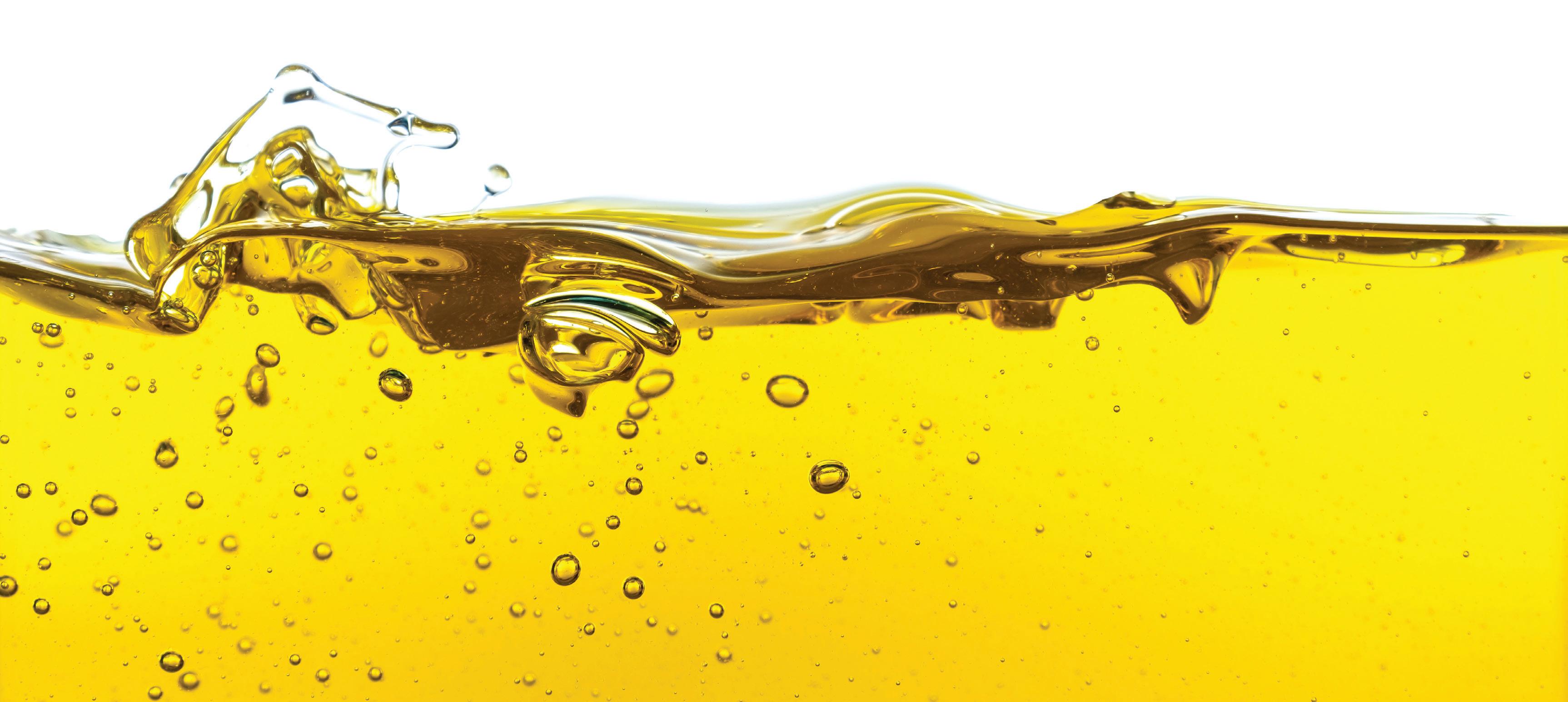
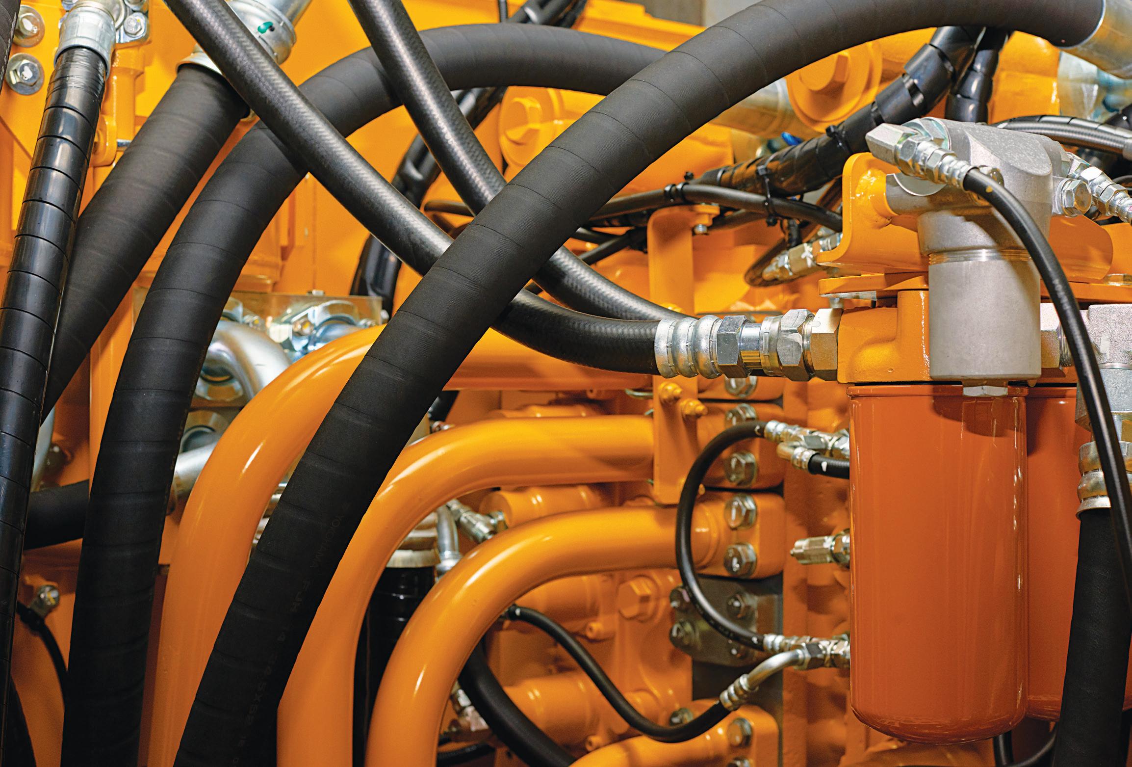
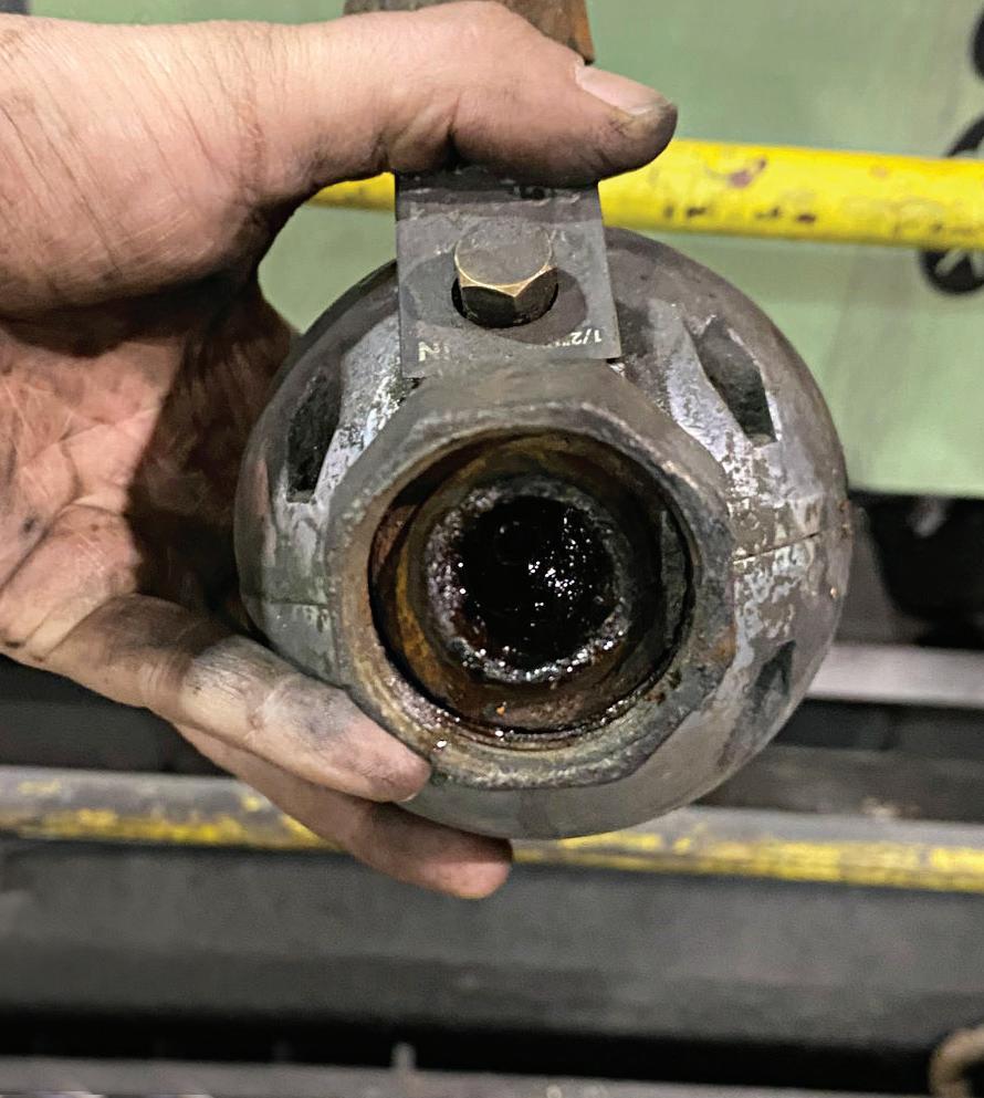
in hydraulic fluid. Once it enters and becomes entrained, it's a pain to remove. If it goes undetected or unmitigated, it can delay system response, decrease performance, degrade the fluid, and wreak havoc on hydraulic pumps.
“It’s not like the bubbles that rise to the surface in your glass of beer. The air becomes almost atomized, and because the oil is so turbulent, it looks like a milkshake or a latte,” said Jim Oftelie, CEO of Amtech and a seasoned mechanical engineer.
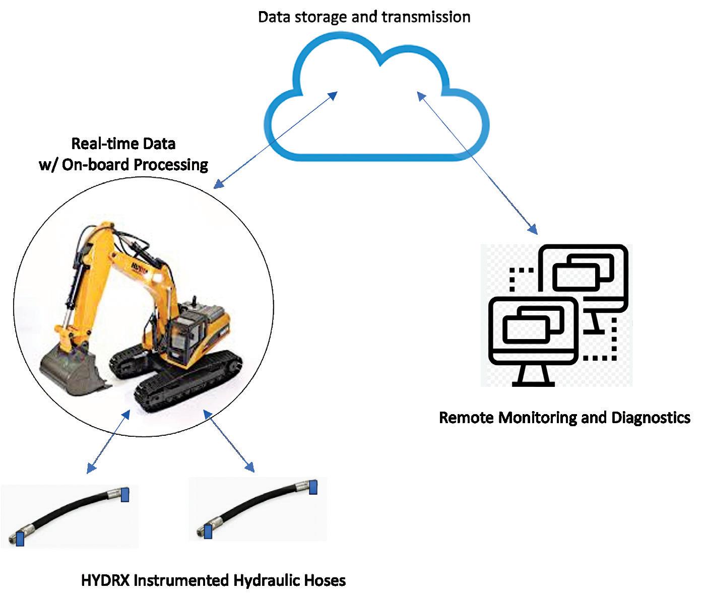
Oftelie found a unique solution to measure and monitor entrained air in hydraulic fluid that gives OEMs real-time data. With the HYDRx Gas Void Fraction Monitoring System developed by Daniel Gysling, CEO of CorVera, Oftelie places transducers along a hydraulic hose and collects data on a laptop. The HYDRx uses proprietary sonar technology to measure the speed of sound within the hose and determine the amount of entrained air in the oil. His hunt for a solution like this began 20 years ago.
“I took a job right out of college as a service engineer,” said Oftelie. “I was a subject matter expert in hydraulic systems and products, and I would be the guy helping people troubleshoot and figure out the correct service parts and
write technical bulletins. I'd be on the phone, and with a day's notice, I'd go to the other side of the country, or anywhere in North America, to help valuable customers with our products.”
Through experience, Oftelie developed a keen understanding of reservoir design and the impacts of aeration.
“I remember thinking, 'Boy, I wish I knew of a way to measure air in hydraulic systems,'” he said. “It's the one thing we really don't know anything about. We can get pressure, temperature, chemistry. We can use particle counters, filter the oil, separate out the water — everything. But air...my friends and I call it 'the ghost of the machine.' It comes and goes, and we really don't know what's going on.”
After a few job changes, he joined another company as a hydraulics specialist working mainly with machine braking and steering systems. During that time, he discovered the CorVera technology that could measure the
amount of air in hydraulic lines in real time using acoustic analysis and software.
“I went crazy. It was just amazing. I couldn't sleep for two weeks,” said Oftelie. “When I found it, I brought it to my boss, and he said, 'That sounds pretty good, here's a budget. Why don't you buy a couple of these systems and do a feasibility study along with the work you're doing with our internal customers?' Because that's what I'm supposed to do as an engineer — find new and better ways of doing things.”
Oftelie performed a three-year feasibility study at a tech center in Peoria, Illinois, and installed the system on a couple of machines at Caterpillar's proving ground in Tucson, Arizona. After gathering and analyzing a lot of data, he showed aeration was present in the machines' hydraulic systems and proved that he could quantify and measure it.
Not only is this fascinating, but it also heralds a mindset shift in diagnosing and mitigat-

ing aeration. Fluid power professionals often use experience and gut instinct to evaluate problems they can't see or measure. Now, they'll have the numbers to prove it and select the right solution.
“I call it the black art of hydraulics,” said Oftelie. “We can understand the functions of air and what it does in your system, and come about it by process of elimination saying, 'Well, we don't know what's going on, but that reservoir is kind of small and your system is overheating.' There's a flag in the field right there. Problems associated
with high temperature, and oil properties change — it oxidizes, starts smelling funny, and turns black. You got all these symptoms of aerated oil, but what do you do about it?”
Using a larger reservoir or installing a baffle could mitigate the symptoms, but it might not solve the aeration problem. Plus, an OEM may not have room to install larger equipment. Without any data, the OEM may waste effort, decrease machine efficiency, or make decisions that don't work and add cost.
“I could put a system on their machine, leave it on there for six months, and they could get six months worth of aeration data on a continuous basis. That would be immensely valuable,” said Oftelie. “Once they understand that number, they could compare it to other machines that have the same problem, or whatever. Engineers can take this and run with it in any direction. It's up to them.”
Oftelie emphasizes that the system gives OEMs data passively and continuously. There's nothing to break, and there's no need to worry about running the machine at a certain pressure, altitude, or other environmental condition. None of those types of restrictions apply.
“Based on the acoustical properties of the oil, we can measure how the oil deals with sound. The algorithm will tell us exactly how much air is in the oil,” he said. “Instead of talking about it qualitatively, we move to quantitative.” FPW
Amtech amtech-usa.com CorVera corvera.io


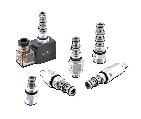
Check
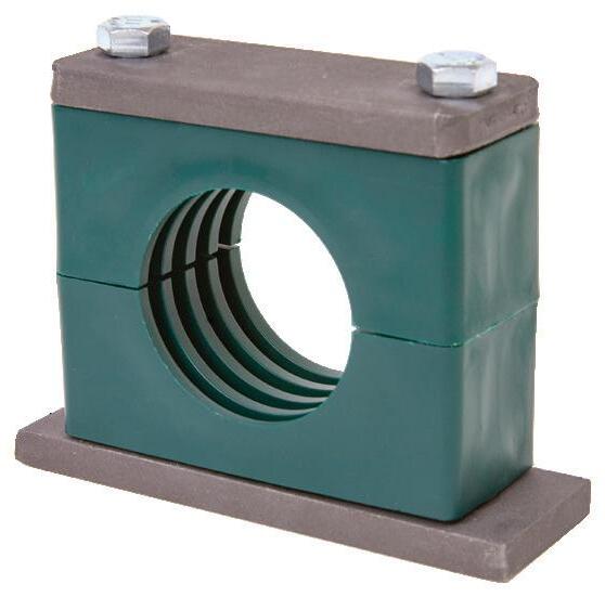
Flow
Needle
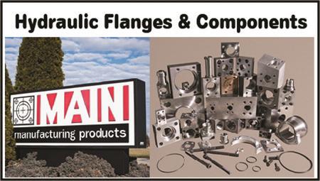
Flanges & Adapters
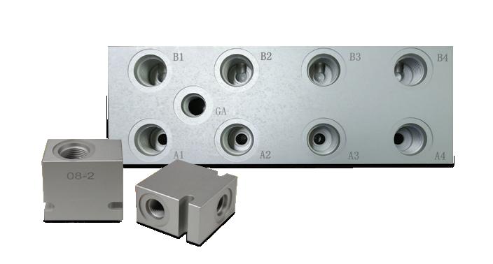
Bar & Custom Manifolds
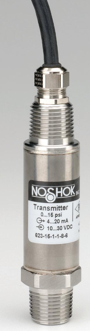
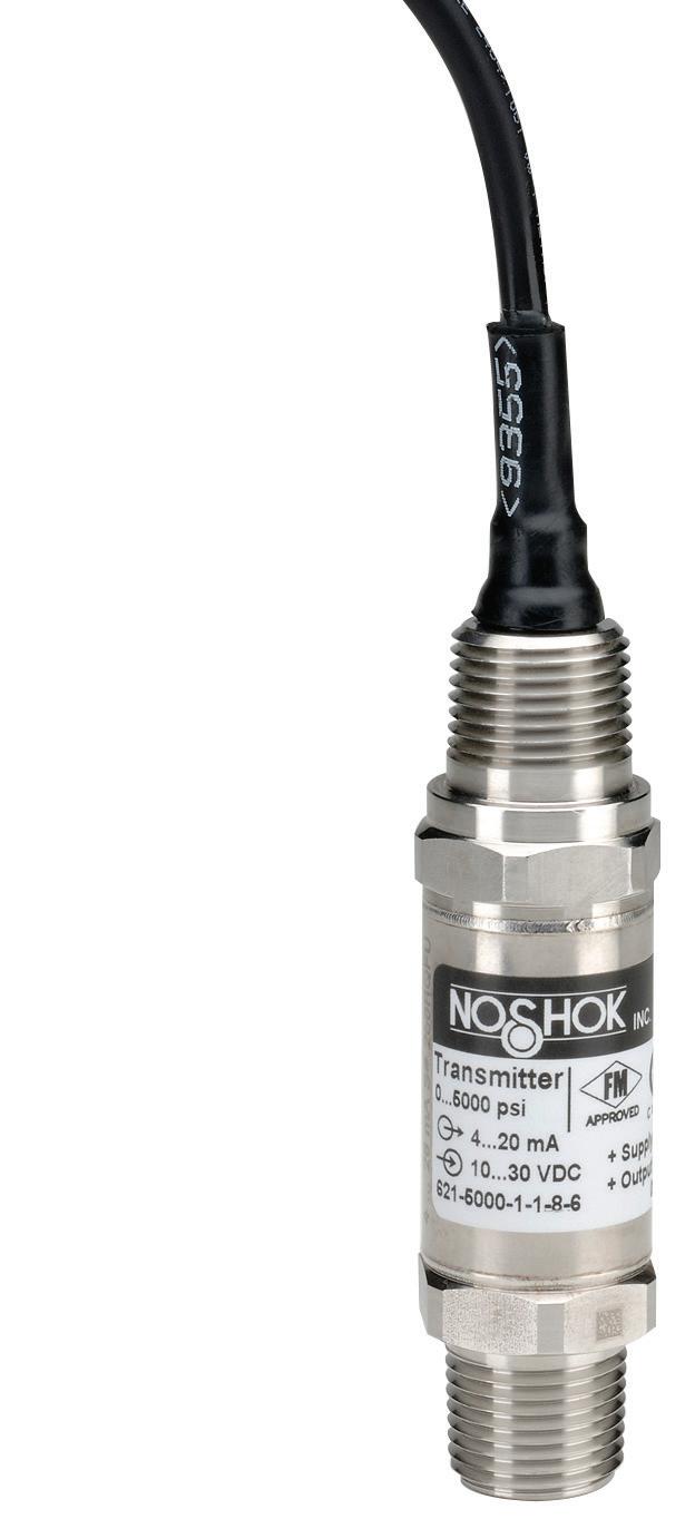
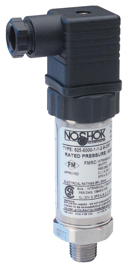
Pressure Gauges & Snubbers
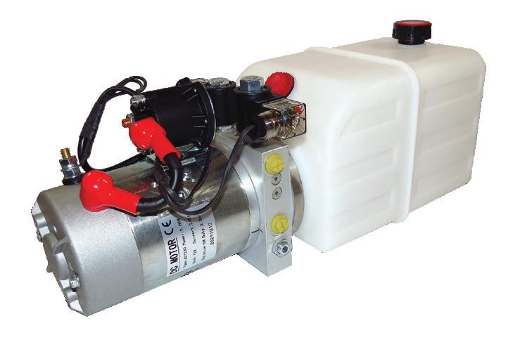
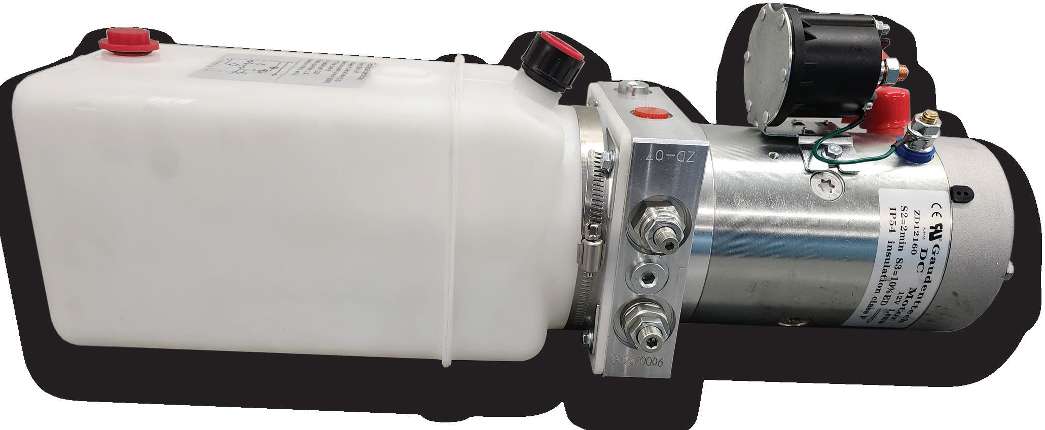
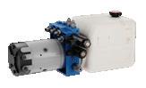
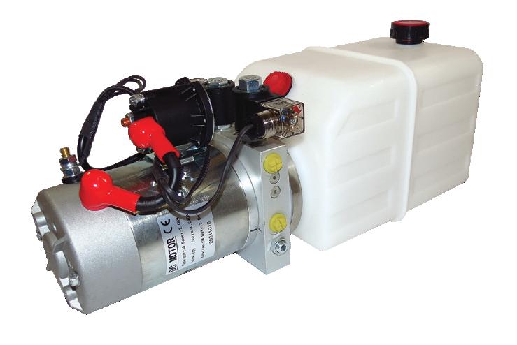
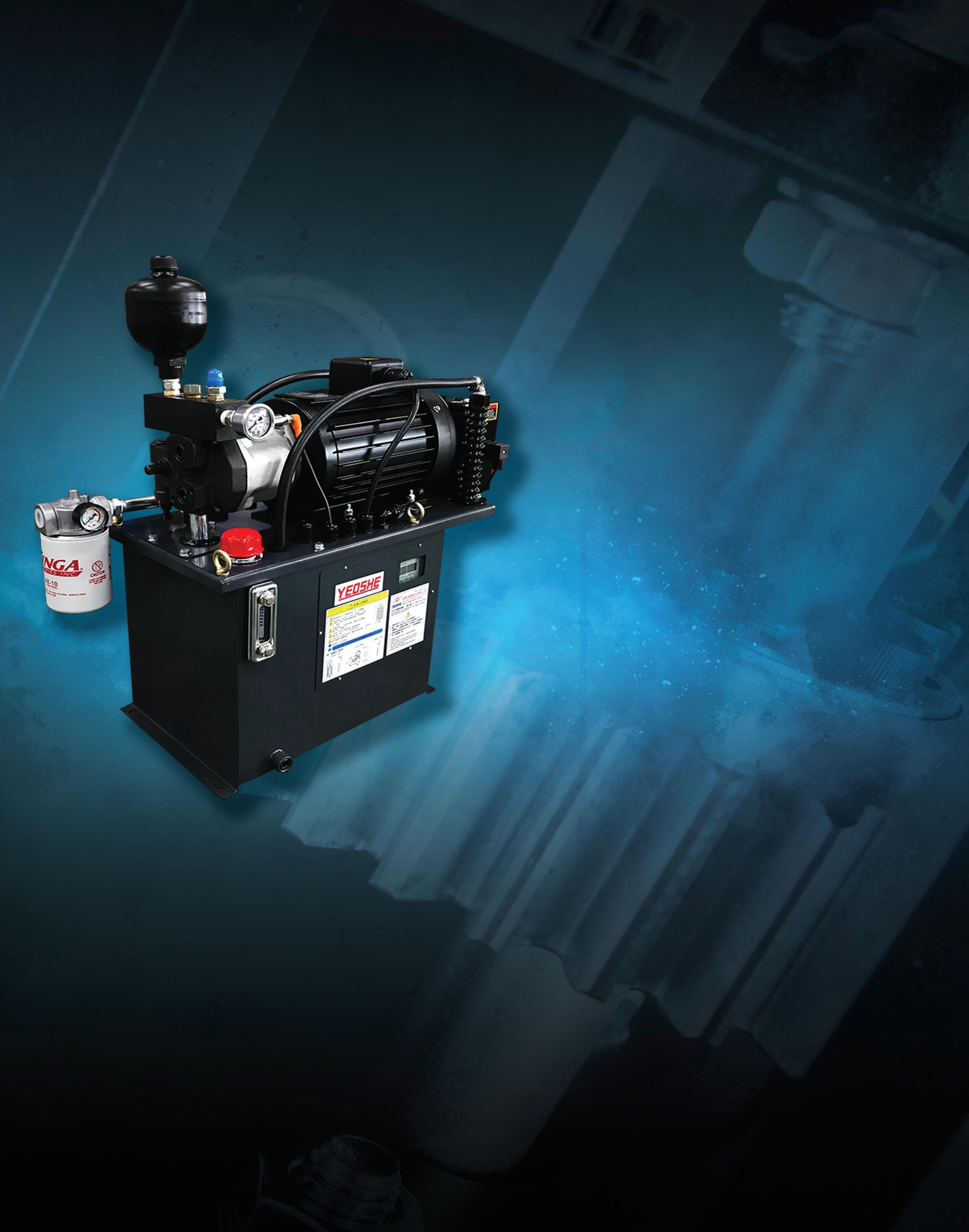
SSW Power Unit Systems
Transfer Pumps
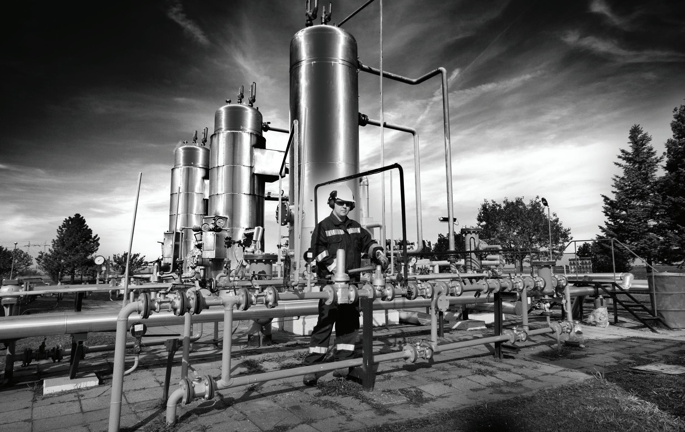
Industries Served:
• Oil & Gas
• Industrial Hydraulics
• Mining
• Forestry
• Chemical & General Processing Plants
• Medical
• Aerospace
• Factories
• Mobile Equipment
• Defense
• Machine Tool
• Testing Equipment
• Ocean Depth Technology
• Automotive
• Food Processing
• Agriculture
• Industrial
• Aviation
• Petrochemical
•
Josh Cosford • Contributing Editor
HYDRAULIC HOSES ARE CONSTRUCTED from a combination of soft polymers and wire reinforcements, most commonly made from high-tensile steel. Although the choice of hydraulic fluid plays little role in the degradation of steel, the materials chosen for the inner tube and outer cover are affected by the fluid you run through your hose assemblies.
The primary consideration for compatibility with any given hydraulic fluid is the tube construction. The five most popular choices for inner tubes are nitrile (nbr or Buna), neoprene, EPDM, Viton and thermoplastics, with nitrile being the most common. Nitrile is a versatile material great for use with most hydraulic oils, as well as high water-based fluids when using the hydrogenated nitrile variant.
With regular nitrile (NBR is a contraction of Nitrile Butadiene Rubber), the cycles of heat and oxidation can lead to swelling, softening
and cracking over time when you run water or water glycol. Over time, your hose will experience reduced mechanical strength and eventual failure. EPDM is your best bet for waterbased hydraulic fluids. You will often find pump suction hose one and the same as “truck hose,” which is often constructed of EPDM and also rated for vacuum service.
EPDM (Ethylene Propylene Diene Monomer) is the go-to material of choice for applications that require a water-based fluid. Such fluids could be ethylene-glycol mixtures or water-oil emulsions and are a top choice for places like a steel mill. Because of the high heat (both ambient and localized), any hose leaks with these fluids won’t turn your hydraulic plumbing into a flame thrower. I’m not going to provide the explication of PTFE, but just know we also call it Teflon, and it makes a superior choice for water-based fluids in extreme heat
applications, although it does make some flexibility sacrifices.
Viton (fkm) is a type of fluoroelastomer that also provides superior protection against aggressive fluids such as polyol ester and phosphate ester, although their general use of those fluids is starting to wane. Phosphate ester is best known for its use as a fire-resistant fluid for aerospace, but it made its way into steel mills as well. Both types of esters are fully synthetic and designed to avoid quick ignition when exposed to flame and extreme heat. In such cases, alternate hose materials such as nitrile and EPDM will degrade and fail, so avoid using them for fire-resistant fluids of all types.
Of course, you must also consider the outer cover when discussing compatibility, especially when you factor in the ambient conditions of your hydraulic hose. Industrial environments might have aggressive chemicals or solvents that could damage or degrade a standard neoprene cover. Again, this is where Viton comes into play, which is resilient in the face of everything except water, strangely enough, so mobile applications with chemical exposure may require more exotic solutions, such as PTFE with stainless steel braids.
By respecting the traditional recommendations for chemical compatibility, you can be sure to select the appropriate hose material to create the most effective and reliable hose assemblies. Although off-the-shelf hose provides a solution to 90% of the applications you will see, make sure you know all the details of the machine and environment to prepare for all scenarios. FPW


Ron Marshall • Contributing Editor
AN INDUSTRIAL PLANT started having trouble with its air dryer. No matter what the maintenance personnel tried, they could not achieve adequate dew point values. Nobody suspected the upstream condensate drain — especially because, when tested, it did not release any excess condensate or oil. Finally, it was disassembled and found to be com pletely full of “gunk,” rendering it inoperative.
Compressed air systems generate con densate as a natural by-product of compress ing and cooling air. Properly managing this condensate is critical because it can carry contaminants such as oil, particulates, and water into downstream components. Con densate drains play a vital role in this process by preventing these impurities from reaching and damaging sensitive equipment such as air dryers, filters, and end-use applications. Without effective condensate drains, accumulated moisture and contaminants can cause significant issues. Air dryers, which are designed to remove water vapor from the compressed air, can become overwhelmed if excessive condensate enters the system. This not only reduces the efficiency of the drying process but can also lead to premature failure of the dryer. Similarly, filters are intended to capture contaminants, but when overloaded with moisture and particulates, their efficiency declines. Clogged filters can compromise the quality of the compressed air, affecting both process performance and the longevity of downstream machinery.
End uses that rely on clean, dry compressed air may suffer from contaminationrelated problems. For example, in applications such as painting, packaging, or precision manufacturing, even small amounts of moisture or particulates can result in defects, product quality issues, or production downtime. Effective condensate drainage ensures that the air reaching these critical applications is free from contaminants, thereby
maintaining operational efficiency and protecting the integrity of the finished product.
The installation and maintenance of compressed air condensate drains are essential for preserving the performance and reliability of air system components. By preventing contaminants from fouling air dryers, filters, and end-use equipment, condensate drains contribute to improved system efficiency, reduced maintenance costs, and higher quality outputs in industrial applications.
The drains at the industrial plant were cleaned and reinstalled. The plant is currently monitoring the air quality with no troubles reported. The drains have been added to their maintenance schedule — to ensure this problem does not reoccur! FPW

Editor’s note: In this new multi-part series, Devin Purcell will tackle the skills shortage that the fluid power industry is facing and offer creative solutions to address this challenge.
about the brain drain that we are experiencing in the hydraulic industry, I now offer some strategies that you can use to increase the knowledge transfer from experienced repair technicians to junior repair technicians.
One of the best ways to cover all aspects of learning is to outline the learning objectives that you want to cover during training. Learning objectives are simply described as: what learners will be able to complete/ repair/diagnose because of the training process they have completed.
Outlining and documenting your training process is important. While you could simply jot down on a piece of paper what you expect the student to learn over the course of training, this is not effective. You should think of processes being as effective as the time you put into them.
To bring more professionalism to your standard processes, think of learning objectives as your agreement with the learner: if they pay attention and put in the work, the learning objectives outline what skills they will have after the training is completed.
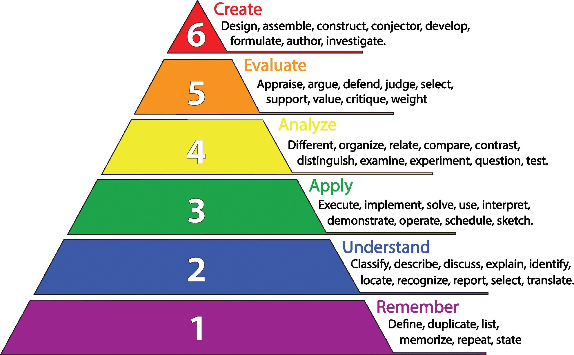
So how do we create simple to understand learning objectives? Educators use Bloom's Taxonomy to outline six levels that each show a higher level of understanding of the material that is being learned. They range from remember, which is simply the ability to remember facts, to the highest level, create.
If you have the time to study Bloom's Taxonomy, you will have a secret weapon when making new learning objectives. Time however, is not always something we have. So how can we make learning objectives that work for us?
Step 1. Take your list of training needs/ requirements that you have previously outlined and convert them to simple one or two
BLOOM'S TAXONOMY OUTLINES SIX LEVELS TO SHOW HIGHER LEVEL UNDERSTANDING OF MATERIAL LEARNED.
sentence topics. Make the sentences specific — you want to outline “specific” tasks that they can complete. For example:
This — learner should know how to reseal hydraulic cylinders
Not This — needs to know how to repair hydraulic cylinders
Step 2. Convert your point form notes into complete sentences, such as:
This — The learner will be able to demonstrate the proper process of re-sealing hydraulic cylinders.
Not This — learner should know how to reseal hydraulic cylinders
Step 3. This is where things can get as complicated as you want them to get. In step 2, I added the word demonstrate. This is a verb, or action word that has been added. This is where Bloom's Taxonomy can help us write better learning objectives. By using the word “demonstrate" I can test the learner’s ability and understand that they have applied what they learned and know how to properly reseal a hydraulic cylinder.
Step 4. Be as specific as you want to be.
For example, if you are having issues with your junior technicians identifying piston seals correctly, you can include another learning objective to ensure this is covered during training. For example: The learner can explain the proper procedure to find correct piston seals for a hydraulic cylinder.
While this may seem like a lot of work to craft learning objectives for your training program, it is one of the most important steps. Think of it as the agreement between you and your junior repair technician of the things they are going to learn. Take groups of learning objectives and place them in a simple timeline. Without this, the training process can feel overwhelming and unachievable.
By using proper learning objectives and a timeline we can ensure that the training process is not only achievable but can be completed in a reasonable timeframe. FPW
Devin Purcell is a repair professional with more than 20 years of industry experience. As a freelance writer and technical trainer with an OEM forestry manufacturer, these skills are used to enhance the performance of learners. Contact him at devinj.purcell@gmail.com.
Edited by Mary C. Gannon • Editor-in-Chief
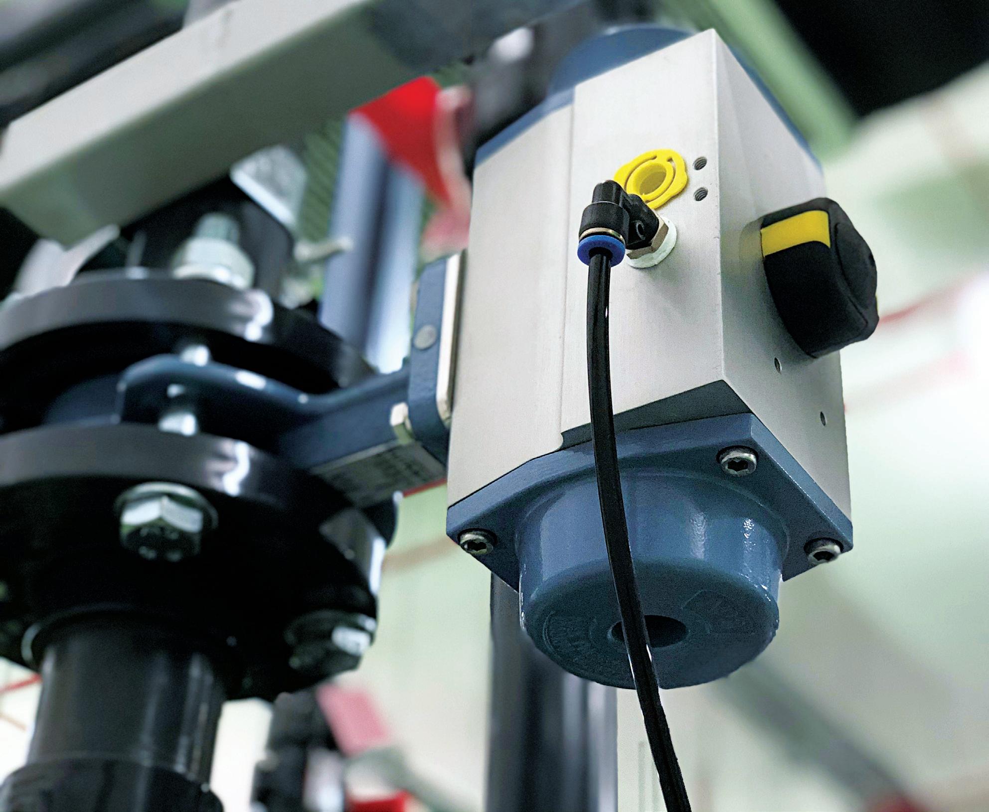
AN ELECTROPNEUMATIC FLOW CONTROLLER PROVIDES precision control of the flow of a gas to an actuator. They are most commonly used to control the flow of air to an actuator; thereby controlling the speed which the actuator extends/retracts or rotates. To appreciate the advances that electropneumatic flow valves provide, it is important to understand the mechanical technology they are built upon.
A simple way to control the flow of gas to an actuator is a needle valve. This requires a person to manually turn a knob that gradually slides a needle into an orifice reducing the flow. A limitation of this method is that the air going into and out of the actuator is controlled by the same valve.
The next advancement in flow control was the integration of a check valve into the valve. This allowed for control of the flow into or out
ADJUSTING FLOW ELECTRONICALLY ALLOWS ACTUATOR SPEED TO BE CONTROLLED IN REAL TIME.
of the actuator, allowing the return path to open and pass around the orifice. While both valves provide excellent speed control of actuators, their limitations result from their manual adjustment and one flow point. A common issue in pneumatic systems is that as the actuators wear, the speed is reduced, the seals wear and the flow controls need adjustment.
An electropneumatic flow control provides an automated process for adjusting the flow control addressing the wear example and helps machine maintenance by providing early warning of service or replacement needs on the actuators. They can control the speed of an actuator using a sensor for a feedback loop. For example, in a pneumatic cylinder with a linear position transducer sending the location cylinder rod as it extends, the electropneumatic flow valve can provide more air, which allows
the cylinder to rapidly extend and then slow down when reaching a point where the cylinder is to generate force.
While this example improves the control and knowledge of the actuators in a pneumatic circuit, proportional flow control valves provide two additional control strategies for designers — compensating for pressure changes coming into the system or for flow variations. This provides a more reliable performance of the circuit or machine.
Electropneumatic flow valves combine the flow control with an electrically controlled proportional solenoid. These valves require either a controller of their own or the control signal is integrated into a PLC. Their flow can be adjusted electronically in real time based on feedback from the machine. This allows the speed at which the actuators move to be controlled.
The electrical solenoid can be actuated by either voltage or amperage from the controller/PLC. Typically, a voltage drive solenoid uses 0 – 10 Vdc, while an amperage driven solenoid uses a current of 4 to 20 mA. These electrical values are programmed in proportion to the mass flow rate of the electropneumatic flow control. As an example, 1-V change in the voltage to the solenoid would change the flow by 10 scfm in an application with a range of 0-100 scfm. Mass flow valves are also sized in metric using liters per minute (lpm).
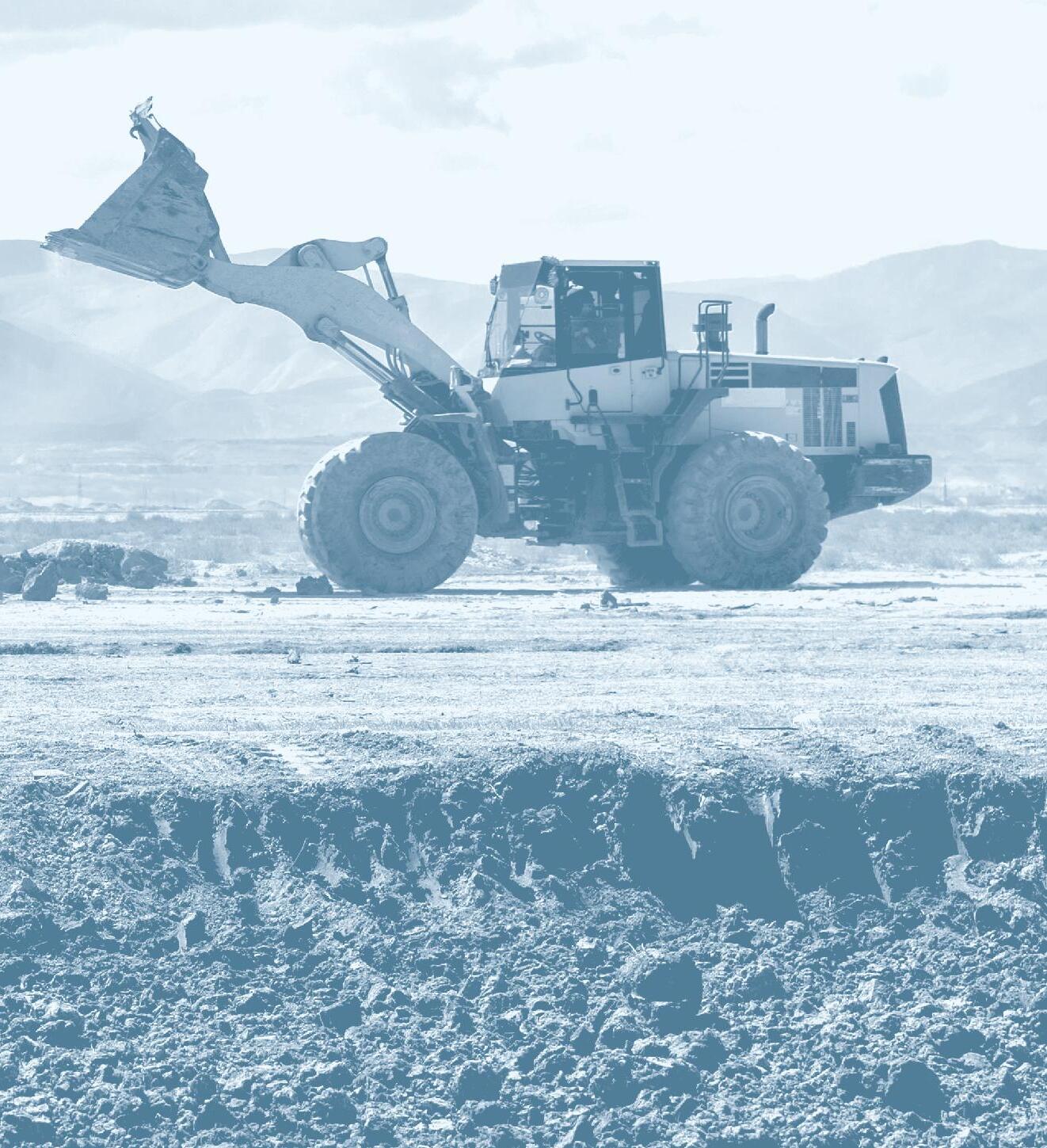
Temperature can impact the performance of the valve. The ideal gas law PV = nRT. (p) Pressure times (v) volume = (n) amount of gas times(r) ideal gas coefficient times (t) is temperature. As the temperature of a gas increases, the density of the gas decreases in a direct correlation which the volume of gas increases. Depending on the temperature range of the air entering the valve, it might require an electropneumatic flow valve that compensates for the air temperature or be programmed into the PLC. This will maintain a constant flow rate through the valve regardless of temperature. FPW
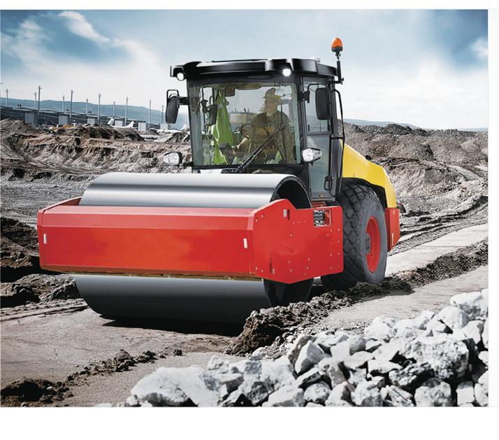


Hydraulics are predominantly used in most mobile crane designs, from the cylinders for lifting, to valves for holding, and more.
By: Josh Cosford, Contributing Editor
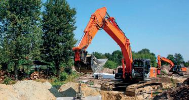
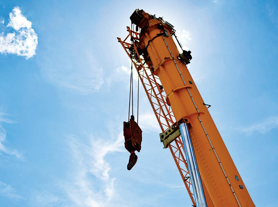
We’ve all seen those crane yards when driving along highways near towns and cities. You know, the ones with their booms reaching high into the sky, proudly advertising the location of an equipment rental yard. They’re the industrial equivalent of the wacky waving inflatable flailing tube man. As much as my hydraulic sensibilities are offended by the apparent disregard for safety by leaving those booms elevated, I’ve never heard a story of one crashing down and hurting anyone.
Mobile cranes are one of the lesserdiscussed hydraulic machines, although they’re often equipped with some of the largest hydraulic cylinders this side of a forging press. Many machines are fully hydraulic, while unique animals like tower cranes may use electric motors for some functions. A crane is a machine that simply lifts or lowers objects too heavy for simpler means. They shouldn’t be confused with equipment such as telehandlers or scissor lifts, which don’t use cable and winch systems. It’s typical to use a telehandler for lifting purposes, but fixed-length straps are used rather than winched cables.
The appearance of a mobile crane differs mainly by the terrain in which it travels. Truck-mounted cranes span from small units mounted to light-duty service trucks and grow to enormous, specialized machines with rows upon rows of tires to support their many thousands of tons com-
HYDRAULIC OUTRIGGERS SECURELY STABILIZE TRUCK-MOUNTED CRANES TO PROVIDE SAFER WORKING CONDITIONS FOR OPERATORS AND SURROUNDING EQUIPMENT.
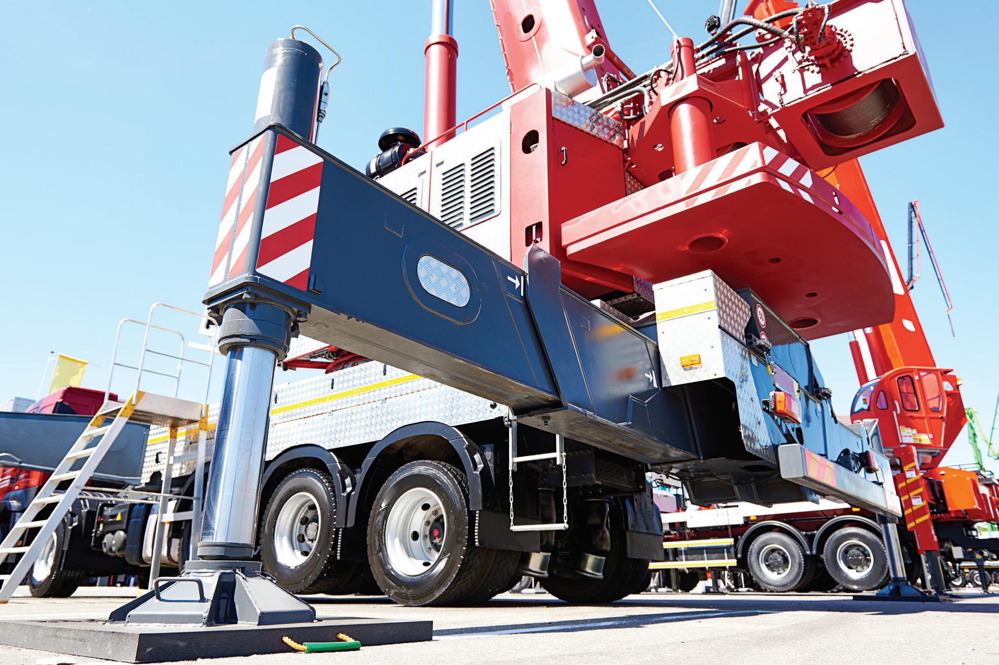
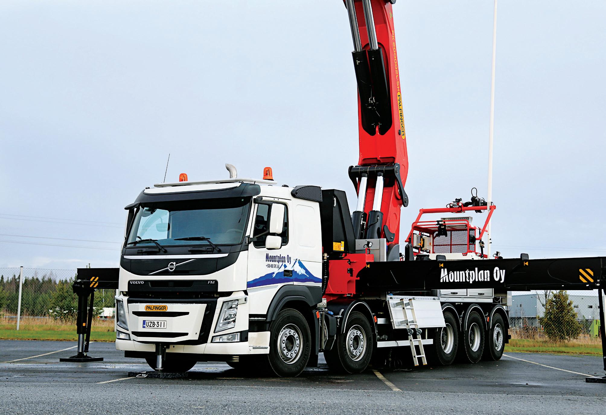
bined vehicle and lifting weights. Truckmounted cranes are used for road-legal on-highway machines, although many are rated for all-terrain use.
If your worksite duties are extreme, the track-mounted crawler crane is difficult to sideline in even the worst ground conditions. Although they look much like an excavator, they are outfitted with booms, winches and counterweights. Their long and wide footprint provides a stable crane base without the need for outriggers, as many other cranes require.
Covering the lighter-duty side of mobile crane technology are the carry deck and
pick-and-carry cranes. These are smaller and highly mobile cranes with plenty of crossovers, primarily differing only where the pick-and-carry crane is meant to transport the load while the carry deck crane remains stationary. These machines are the cranes most frequently offered to contractors requiring a rental, as there is a lot to get wrong when operating these machines and special training is required for more advanced machines.
There is another form of crane that isn’t quite mobile but can be transported and erected anywhere, and that’s the tower crane. A familiar sight in large cities,
these giants seem to pop up overnight yet remain installed for the months or years it takes to erect a skyscraper. You might be surprised to learn that many of these cranes take advantage of hydraulics.
Indeed, if it moves and requires force and speed in a versatile package, you can bet that hydraulics is the first choice for motivation. Each of the above machines range from fully hydraulic (including drive systems) to partial usage. Every crane uses hydraulic cylinders for boom control outside of lattice boom cranes, which use wire rope hoists to lift or lower the boom.
Some of the largest cranes use a boom cylinder nearly large enough to walk through its barrel. With so much weight and safety on the line, you can bet boom hoist cylinders use sophisticated motion control systems (pilot-operated check valves need not apply). Although smaller machines may make do with a traditional cartridge valve, when heavy and expensive machinery is on the line, custom circuits are used to ensure safe lifting and lowering. Such circuits must offer zero leakage for load holding, no drop during boom-up function and no overshoot. It’s reasonable to expect the load control valve to use a half dozen or more valves to help prevent overload situations that could lead to tipping.
Such a counterbalance circuit will have multiple paths to prevent overloading. The primary counterbalance valve does the
heavy lifting (pun intended), where it cannot be lowered except by receiving a pilot signal from the opposite work port of the directional valve. Rather than your traditional cartridge valve, you may also see slip-in logic elements to handle high flow. A separate relief ensures a load cannot begin to lift if the pressure at the cylinder’s cap port is too high. You may even see a reducing valve and orifice on the pilot input to prevent excessive flow and pressure on the control circuit.
Many cranes offer telescopic booms to extend many times their original length and reach higher than a fixed boom. Modern cranes use hydraulic cylinders to extend the boom, but some machines may still use cables. With cylinders, it’s easy to position the boom continuously between each section, where PO checks can safely lock them in place. Some systems use large bore cylinders with cable mechanisms similar to the chain and sheave mast operation of a forklift. When you see cranes with wide, square
telescopic booms, it’s likely these are hiding such a cylinder and cable mechanism to improve effective stroke length.
Despite the hydraulic safety functions added, cranes still do tip, and nearly always for reasons outside of their hydraulic systems. The outriggers could be unevenly located, crosswinds might pull the load away from the crane’s center of gravity, or a dramatically oscillating load could lead to tipping.
Speaking of outriggers; these are another hydraulic actuator common to
the crane. With high loads outside the machine’s center of gravity, providing a broad base is mandatory to achieve high load capacity. Outriggers, also called downriggers or stabilizing legs, move outward from the sides of the machine and then downward to the ground. Simple machines may operate fully manually but fully optioned cranes use hydraulic cylinders for both functions, which are controlled through the truck’s power system. Hydraulic outriggers can lift the crane entirely off the ground to ensure a stable platform with no central fulcrum to risk easy tipping.
Rather than push outward and then down, some outriggers pivot down and out to place the float pads onto the ground, while others move through one diagonal plane to press down a wide footprint.
Regardless of the method by which outriggers brace the ground, they’re all controlled by hydraulic valves. Directional valves could be lever or solenoid-operated and may operate simultaneously or individMASSIVE

ually. Using a single valve, the synchronized outriggers are best suited to flat pavement, while rough terrain is best suited to individual operation. In all cases, you can expect heavy use of pilot-operated check valves, which are less expensive than counterbalance valves and better suited to locking into a fixed position.
Unique amongst the cranes is the tower crane. Although these are sometimes manufactured with little hydraulic influence, this fluid power author believes the hydraulic machines are superior. Pretty much every tower crane uses hydraulics to elevate. The initial crane installation is aided by a truckmounted crane, which hoists and places tower truss sections atop each other before finally lifting the slewing platform into place. However, this initial installation height is limited by the capacity of the helper crane, so subsequent sections must be added
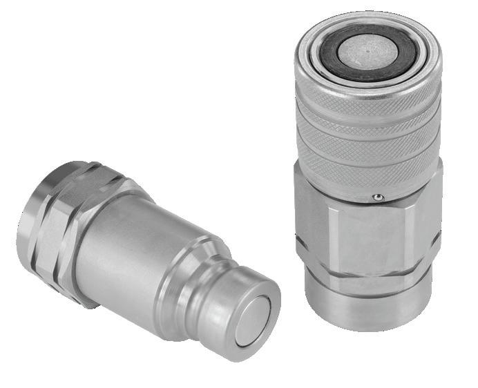
using hydraulics and the crane itself.
A structure called the climbing frame is installed at the bottom of the tower and then lifted to the upper-most truss section. Using hydraulic cylinders (usually referred to as “jacks” in crane nomenclature), the slewing platform is lifted to the height of the next truss section. The crane hoists the next section, and the trolly brings it to the face of the climbing frame. Now, with some manual labor, mechanics bolt the new section into place, and subsequent sections are added if required.
The luffing-style jib crane can tilt its mast to clear condos and towers in congested urban jungles, and although cables are often used, the final boss cranes use hydraulics. The use of a hydraulic cylinder for the luffing function provides a fast and reliable modification to the tower crane that reduces the complexity related to cable-only systems.
A hydraulic luffing jib crane only uses cables for the trolly and hook, which are functions also controlled by hydraulics.
Even the slew motor is hydraulic, which is used to rotate the platform. And rather than a separate (sometimes portable) hydraulic pump for the jacking function, hydraulic quick couplers from the hydraulic system easily attach to the climbing frame for rapid lifting. However, secondary hydraulic power units may also be used.
When installed, the hydraulic jib crane looks like a modern fixed crane, as there is no jib tie mast to support the cables. This compact design also makes for improved ease of transportation and installation, as fewer components require assembly. Hydraulic luffing jib cranes have been in use for over fifty years, and for all their benefits, it’s surprising they’re not more popular. Nevertheless, hydraulics as a whole is the most popular technology for the crane market. Its combination of power, versatility and reliability make it the first choice for most crane systems. You’re not likely to see rental yards free from hydraulically powered mobile cranes any time soon. FPW
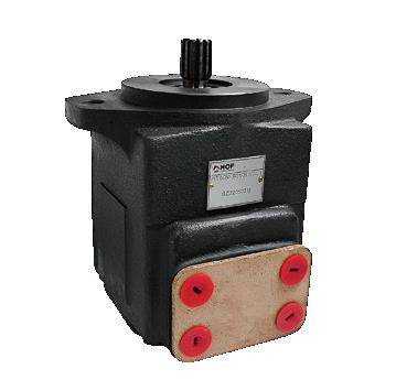
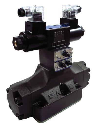
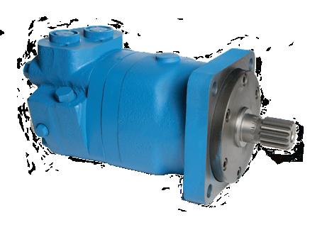
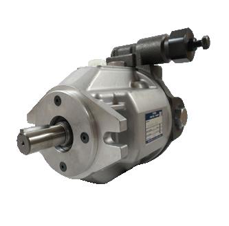
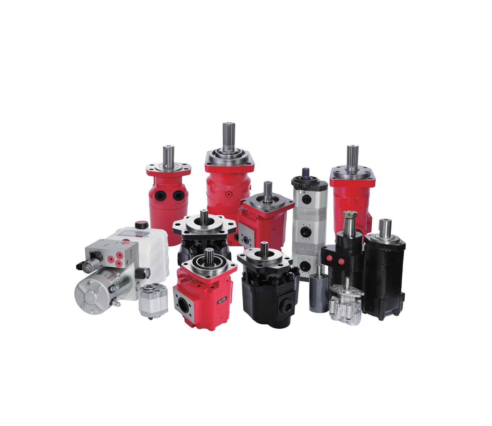
We understand that industrial needs can come in many shapes and forms. Our diverse line of hydraulic components are designed to fit any need you may have. When it comes to reliability, no other product on the market compares to what Yuken Hydraulics has to offer!
Our commitment to quality assurance will give you the confidence that your machinery is running safely and efficiently every time. So don’t settle for anything less.
Edited By: Mary C. Gannon, Editor-in-Chief
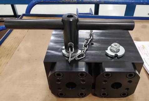
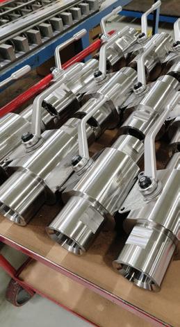
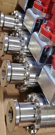
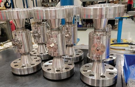
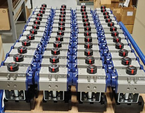
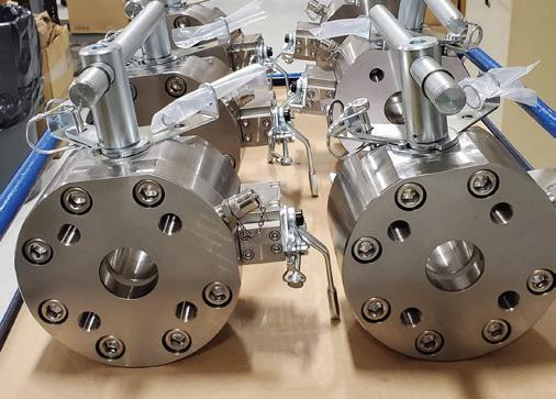
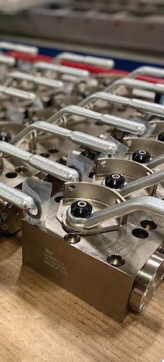
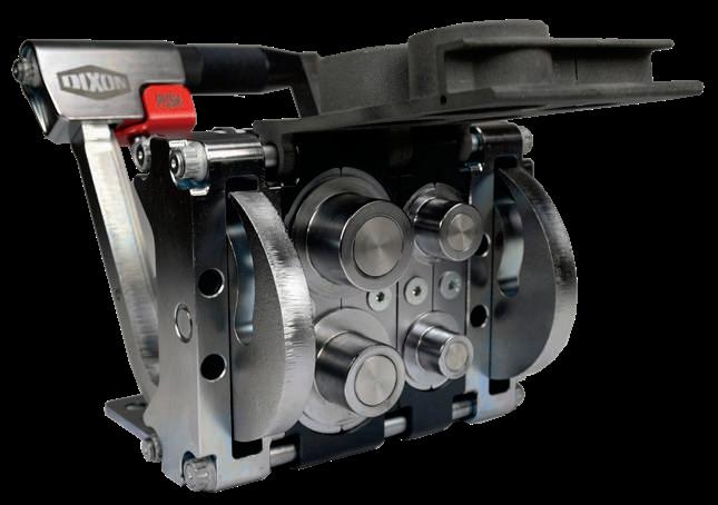
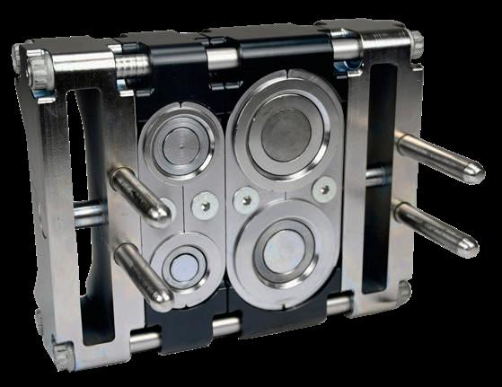
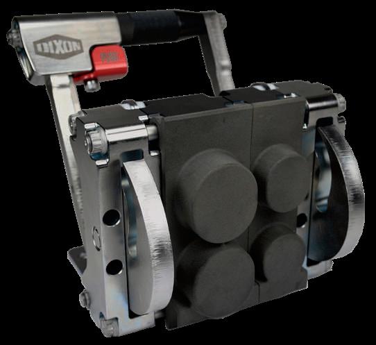
Cold presses using Delta Motion controllers help ensure consistently stronger, more accurate fittings for military vessels.
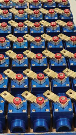
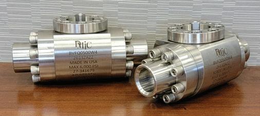
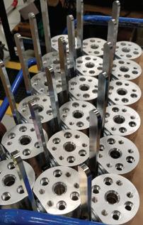
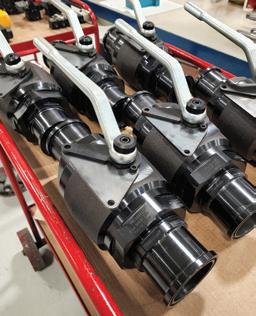
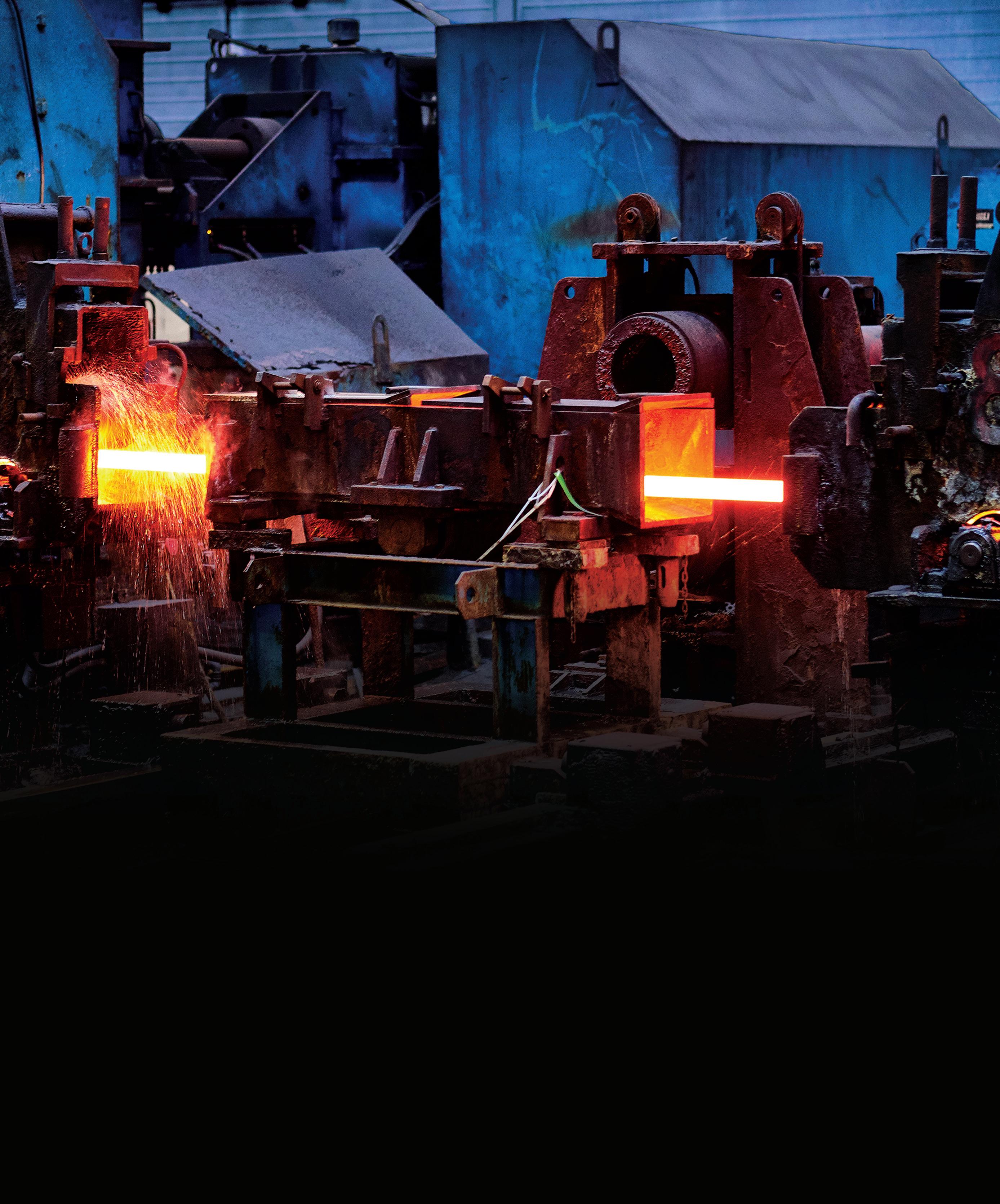
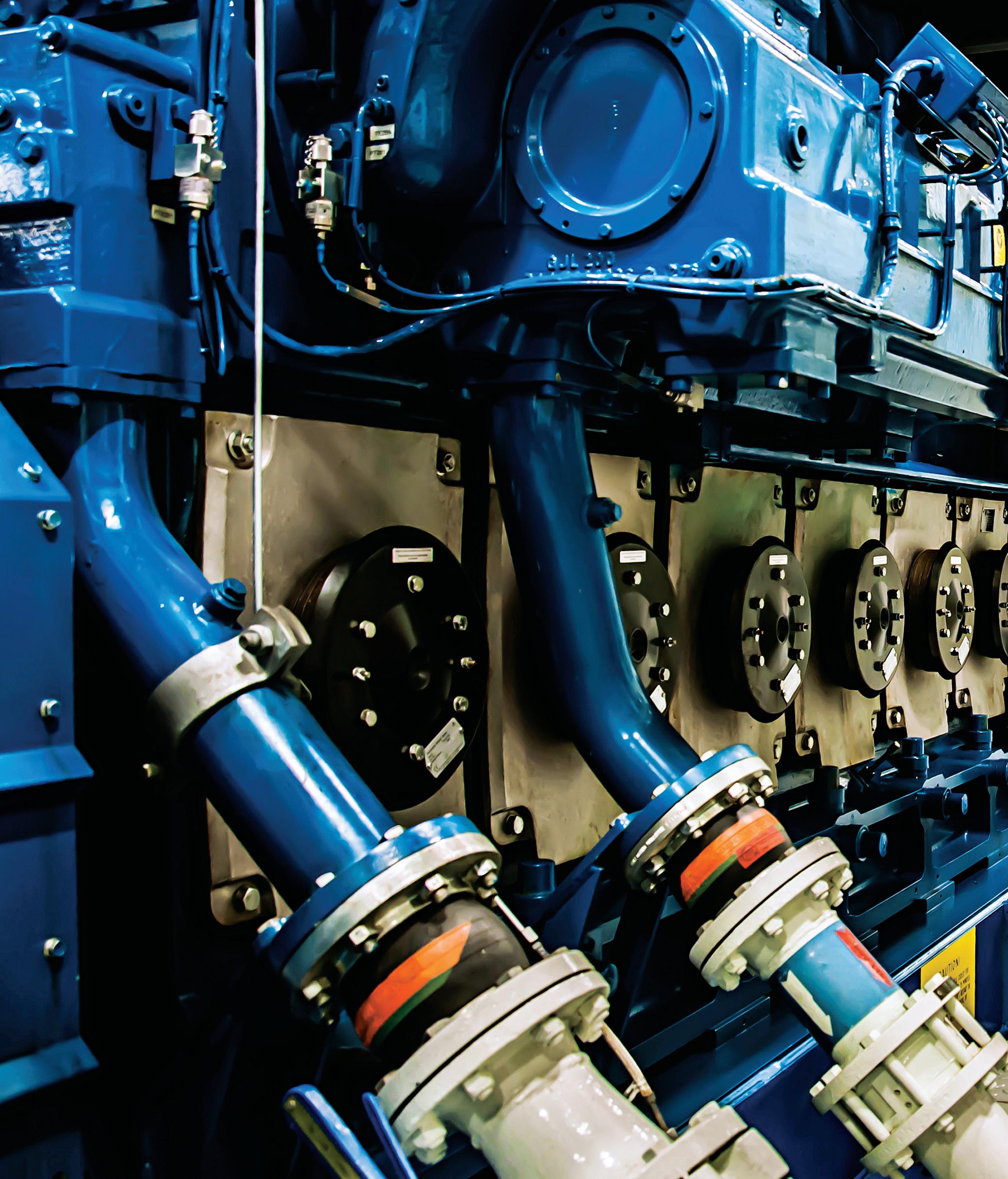
WITH ROOTS IN THE 1960S, W&O Supply has a lengthy pedigree in serving the maritime industry, doing everything from repairing valves to supplying pipe to retrofitting military vessels. The company has 18 branches across the U.S., Europe, and Asia, all dedicated to supporting marine construction, repair, and servicing. Naturally, servicing big ships often requires big fittings — sometimes massive fittings ready to move oil, steam, seawater, or anything else a ship might need.
Cold presses tend to produce stronger, more accurate fittings with greater consistency than hot presses (which can make the metal more brittle). There are obvious environmental benefits to using less energy by producing less heat. Cold press fittings shape pieces by bending them over a mandrel or through a closed die, which attaches to the central press’ ram. However, the military and shipbuilders have stringent specifications to ensure that part materials are in the proper places to reduce stress. A conventional cold-formed fitting might have a pressure rating of 50 to 100 psi. For military and similar maritime applications, though, fittings might need pressure tolerances from 200 up to 6,000 psi. Moreover, their diameter could be anything from 1/4 to 32 in.
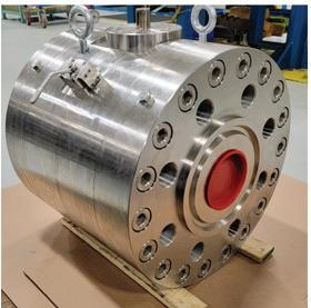
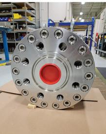
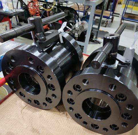
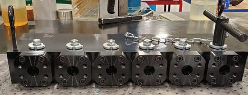
According to William Abbott, director of quality for W&O Supply, the U.S. Navy identified “a significant weakness in the supply chain” for such parts starting around 2017. There weren’t enough suppliers in the world making fittings in those size and tolerance ranges. W&O Supply wanted to address the market need for such fittings (through a new subsidiary called Seamless Marine Fittings) and to do so, it needed a very large, highly accurate press. Such presses are not off-the-shelf purchases; each one must be custom-designed and manufactured. W&O started (relatively) small. As Abbott described it, the first project was “only” a 500ton press able to handle fittings up to 10 in. The design targeted high-strength materials and difficult-to-manufacture items, and it came off so well that W&O significantly scaled up its next iteration.
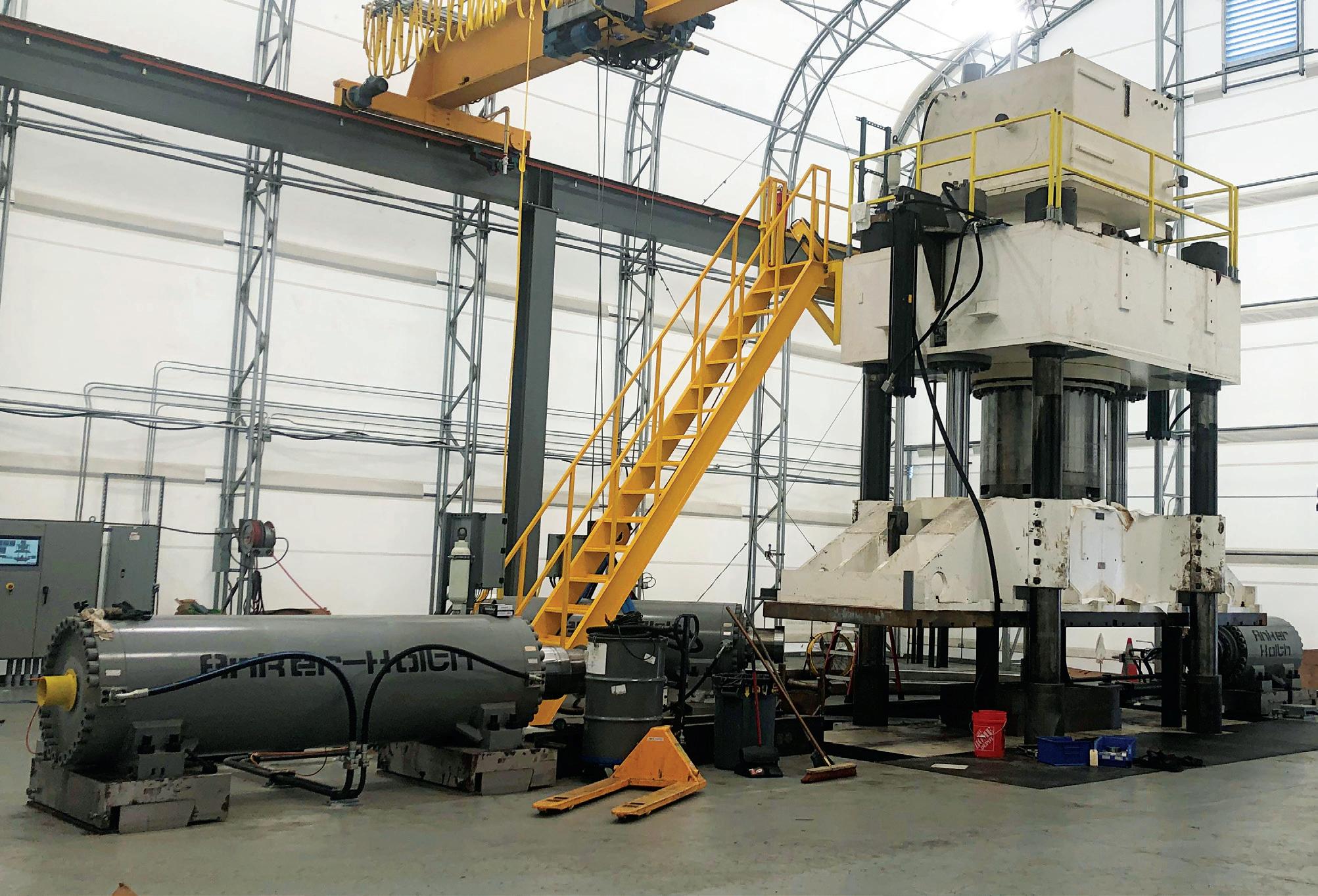
The “full-size” four-post press handles 3,000 tons or six times the pressure of its predecessor. The total force contributed by all cylinders, each of which provides up to 1.2 kilotons of energy force, is 6,000 tons. Abbott noted that it was “specially built to support the construction of military vessels — submarines, carriers, destroyers — although there are some fittings in the commercial world this product would fulfill nicely.”
William Abbott and W&O Supply have tried a range of motion controllers in their presses over the decades. Too often, though, motion control solutions ran up against what Abbott referred to as “the black box effect.”
“They come out and say, ‘This’ll do everything you want,’ and they spew enough technology talk at you to believe them. But then there are too many limitations. Or you can’t do something because it was never intended to do that, and the features won’t support it,” Abbott said. “Now, there are controllers built with such open architecture that you have almost hardware-level access to fundamental components, inputs, outputs, ADCs, and you can change how they do things. But a lot of systems don’t provide that level of access. They’re just black boxes you can’t see inside of.”
Abbott had seen other companies use controllers from Delta Motion enough to
be acquainted with their functions and operation. As W&O planned for its large cold press, Abbott launched discussions with Delta to gauge their confidence level in Delta’s RMC motion controllers' ability to handle the task. He was justifiably concerned because W&O needed to perform certain operations in certain ways that weren’t generally done on hydraulic presses. Once he got his hands on Delta’s RMCTools software, he realized that its simple interface belied a remarkably versatile functionality that “gave us all the access needed to do pretty much whatever we wanted. It became very clear that the product was exactly what we needed.”
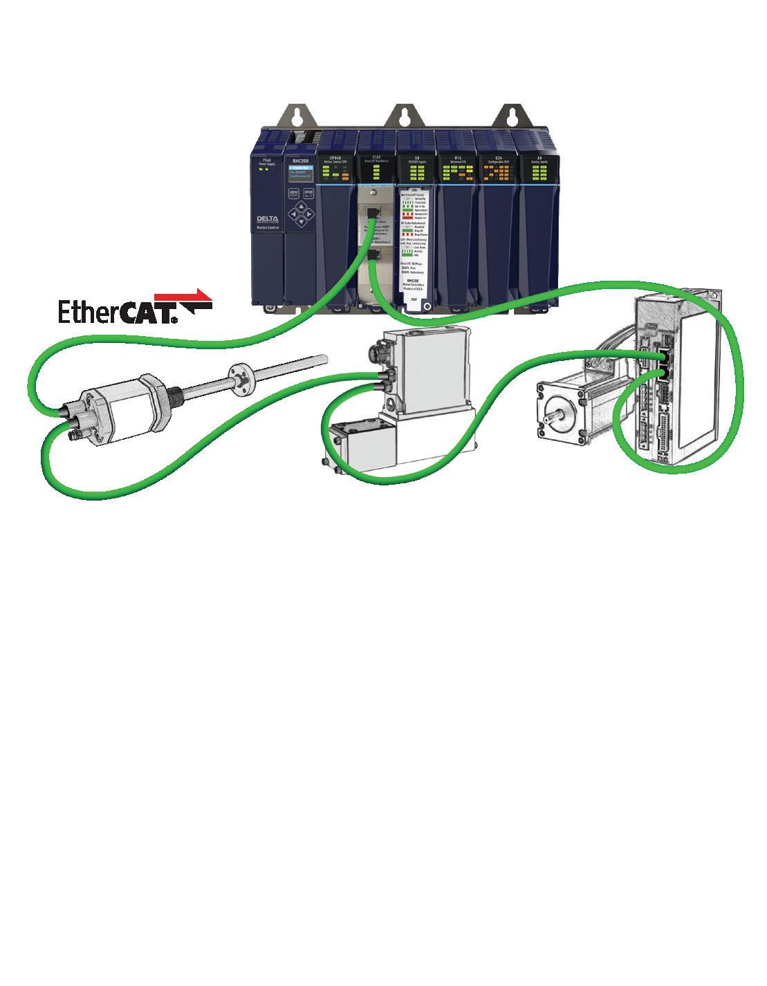
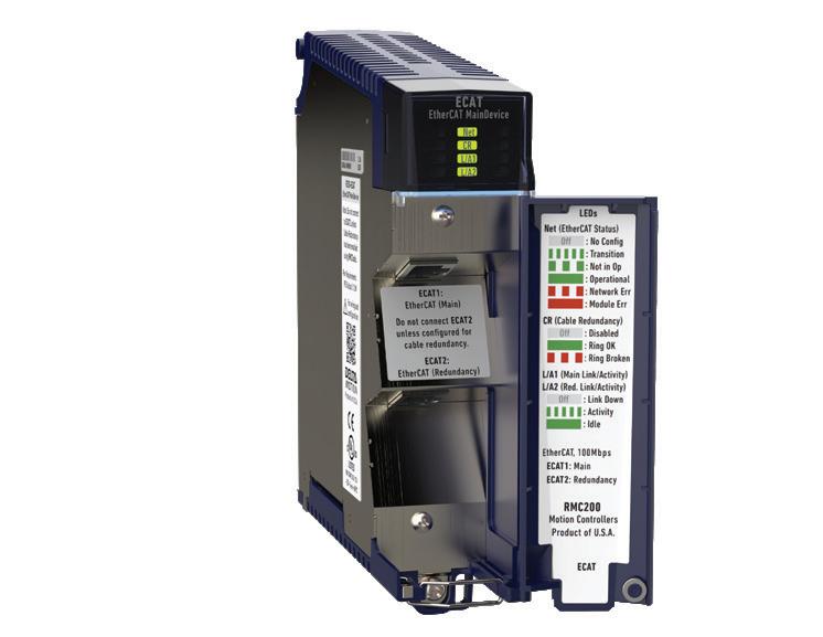
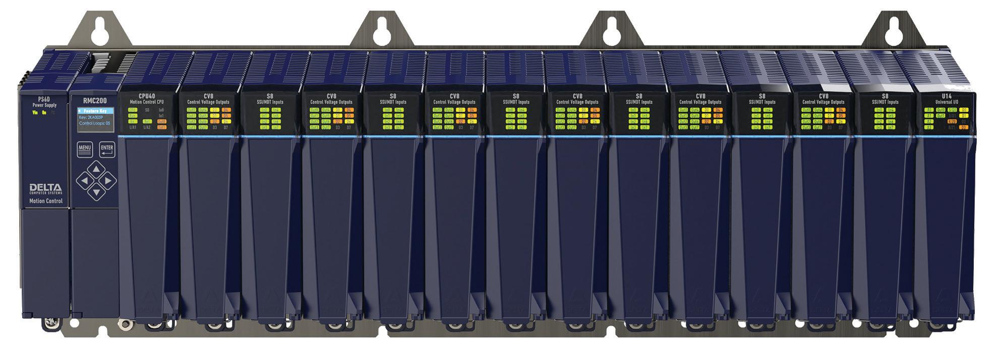
W&O procured a Delta RMC200 motion controller equipped with SSI interface modules, high-resolution analog modules, and two digital channels. The modules were so configurable that Abbott said W&O didn’t have to “worry about buying a special module for a special widget.” Most other controllers he evaluated required special adapters and/or programming, thereby increasing design complexity.
“With Delta,” said Abbott, “I can bring in SSI and analog feedback for position and velocity. It quickly became clear that Delta understood that motion is not just one path and that there are all different kinds of motion. That showed a level of understanding I found impressive because not everybody does that.” Delta’s RMC motion controllers don’t just give a position set point,
they also provide a continuously updated target position, velocity, and acceleration up to 8,000 times per second or 125 μs.
With input from Delta engineers, Abbott collaborated with his hydraulic designers on fine details, such as the selection of valves. He reasoned that anything modulating velocity or pressure to the demands of this project must respond accurately and repeatedly under such high-pressure conditions. This design process was critical to the final solution. The wrong valve would ultimately doom the entire project, as Abbott had found in other implementations.
All in all, the Delta integration could not have gone better, thanks in part to the quality of Delta’s PROFINET connectivity. Abbott notes that typically, one to two weeks is allocated to get a motion control rack up and running. With Delta and the cold press, the team started on Monday morning after getting electronics brought up. They had the racks communicating by midday and cylinders moving that night. Integration was completed in a single day. Similarly, the normal time required for tuning the motion axes on an installation would have been a week. With Delta, it was only one more day.
To make a point of the contrast, Abbott called out the motion control solution used on W&O’s smaller 500-ton press, which he referred to as Company S. He said Company S had recently gotten into motion control and claimed it could do everything needed. “It still doesn’t, and it’s been four years,” he said. “It still does not work as well as what we accomplished in two days with Delta — because Company S knows their own standard, but they’re not motion experts.”
W&O Supply valued Delta RMCTools for its user-friendly interface and powerful features, and especially that it was available at no cost. Abbott noted that many years ago, spending $100,000 on hardware might have resulted in user-free software, but “now it’s flipped.” He said that buying a $5,000 controller might still require a $20,000 outlay to let the controller deliver its promised functionality. Delta’s programming software provides the same powerful feature set
needed to optimize performance, regardless of which controller was purchased. Whether a company opts for the least or most expensive controller in Delta's lineup, RMCTools is included at no additional cost.
W&O Supply chose to purchase Delta's upper-end RMC200, which can control up to 50 axes. This greatly exceeds the application's current needs of five axes, but Abbott had scalability in mind from the outset. In his 40-year career, he has seen machines grow and change over time. He pointed to cold presses from the 1930s and 1940s and how they were built for strength, robust-
ness, ease of maintenance, and scalability. This is at odds with practices from later decades, such as the 1980s, when automation optimized around a single application, and any sort of major application change often meant replacing the entire system. One factor that drew Abbott to Delta was recognizing that the motion control company’s long history in the market had resulted in that old-school perspective on how to make a system that could withstand half a century of use and evolution.
He also admired Delta’s approach to service — referring to Delta Motion’s empha-
sis on knowledgeable and responsive technical support. “I once paid six figures for automation from another company, and it took a week to get a guy on the phone who knew how to use it. These companies get so big that they can’t find the right people. When you finally find the right person, guard their contact info because it can be painful to find another one. But that’s never happened with Delta. Every person I’ve talked with knew exactly what to do. That indicates to me a unique caliber of training, understanding of customer needs, and living up to those needs, both with people and product quality. If I had it all to do again,” Abbott added, “I’d pick Delta in a heartbeat. Since commissioning this application, we’ve had zero failures, and we’ve had to make zero adjustments. The motion system has been in continuous operation since inception and continues to deliver unmatched performance.” FPW Delta Motion deltamotion.com

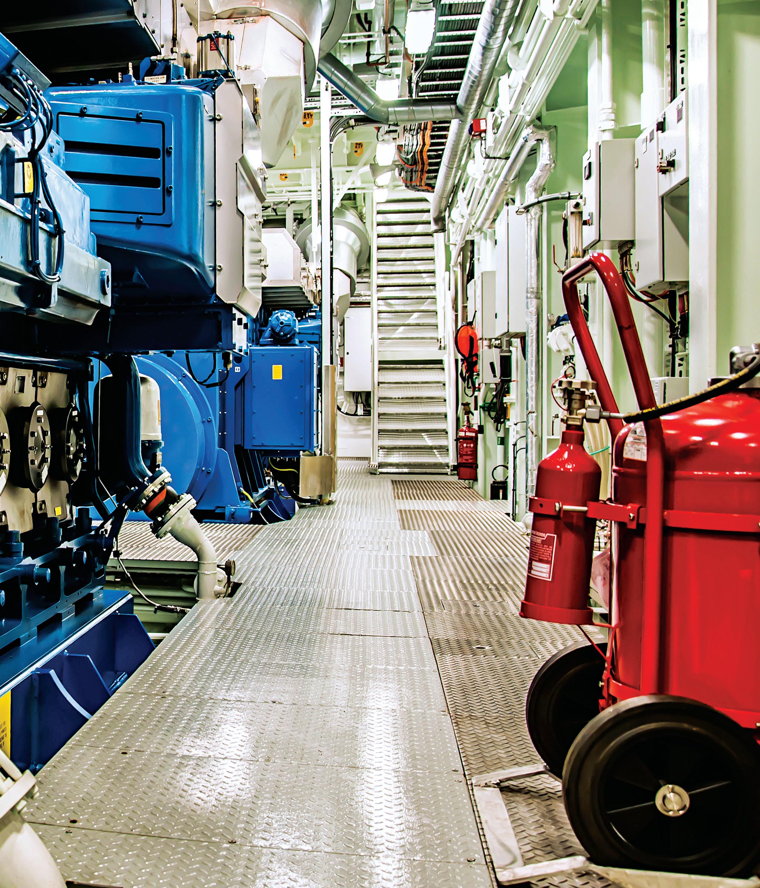
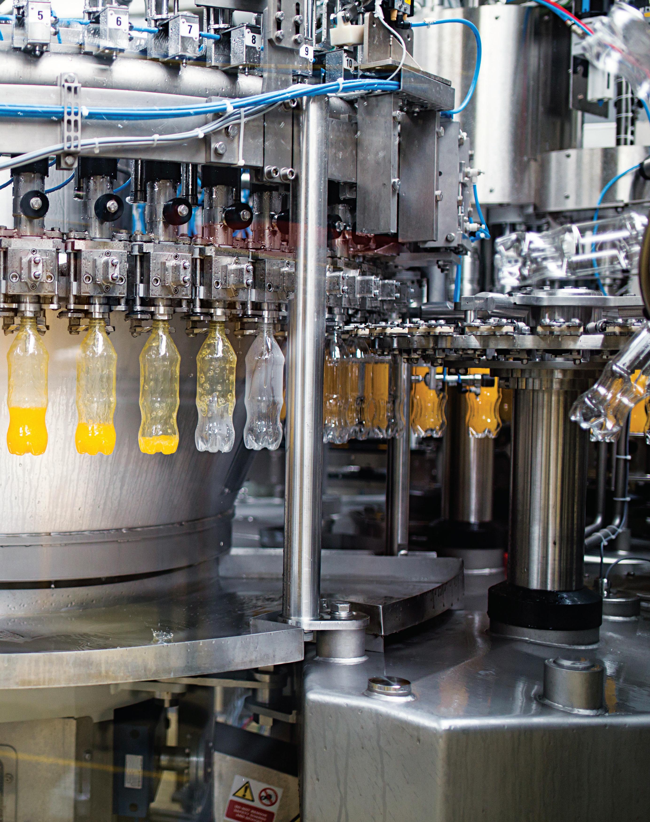
Pneumatics technologies offer the clean designs and reliable operation required in food and beverage processing. By:
Josh Cosford, Contributing Editor
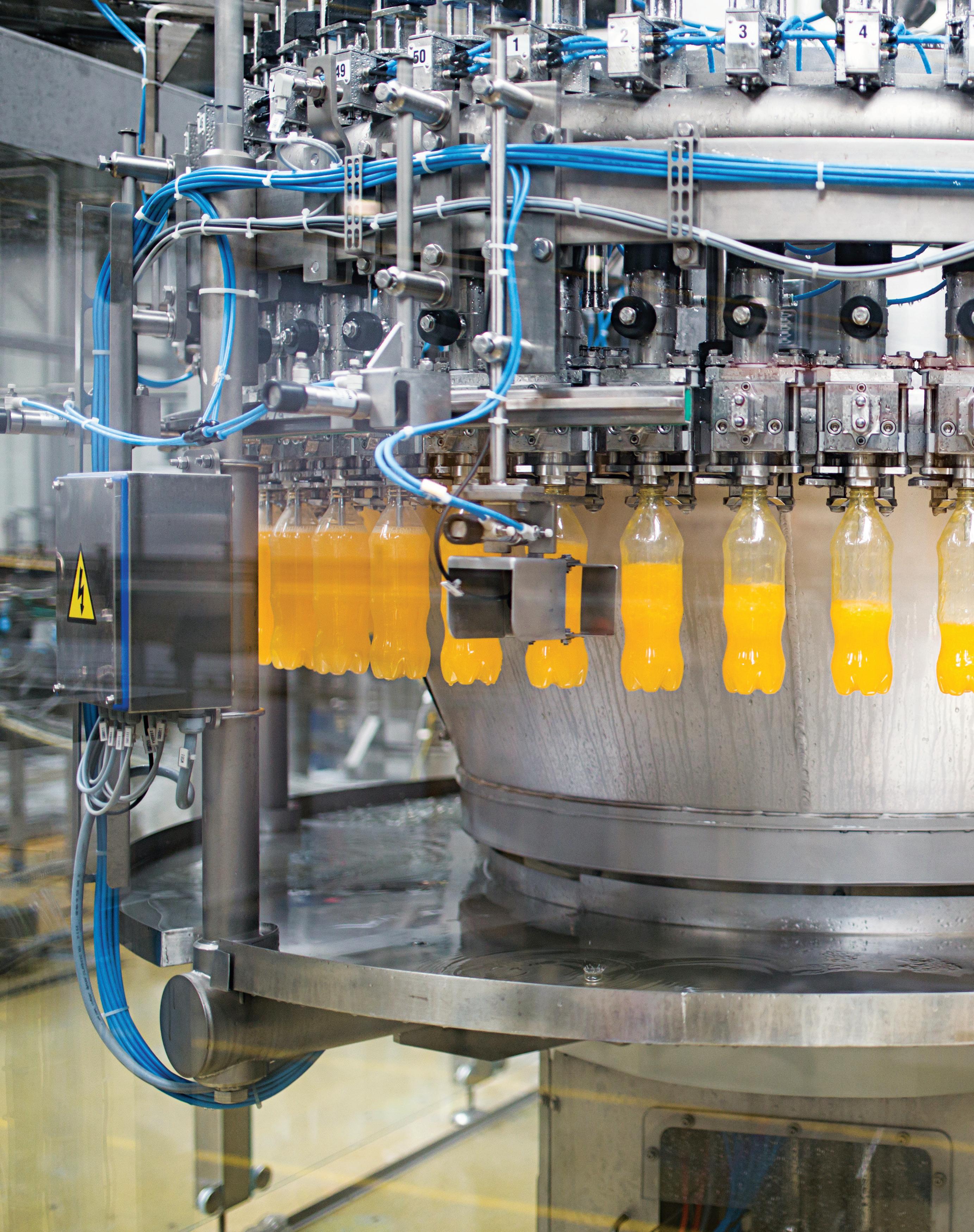
THE FOOD & BEVERAGE INDUSTRY IS unique in many ways, not the least of which is the obvious observation that it’s the only industry providing us with the nourishment for life. Unless you’re living off the land independently, you’re the benefactor of this multi-trillion-dollar industry that provides all the items in our pantries and fridges, ranging from produce to snack foods.
The other reason food & beverage is unique stems from the specific special requirements of the machinery and its environment. The industry is highly regulated, with various government agencies ensuring compliance depending on the operation’s location. Strict health and safety guidelines aim to reduce the likelihood of contamination, thereby preventing poor outcomes for consumers at large.
Contamination in manufactured and pro-
cessed foods and beverages takes many forms, such as microbes, chemicals, physical objects, and allergens. Bacteria, viruses, fungi, and parasites may all potentially find themselves lurking within food and beverage products, each with the potential to cause illness and harm. Chemicals ranging from pesticides to heavy metals or from additives to cleaning agents could also find themselves accidentally infecting your food.
Nearly everyone has found an object in their commercially prepared food and drink, which ranges from metal or plastic pieces broken off from machinery or, heaven forbid, hair or band-aids. And, of course, we’ve all seen those package label disclaimers that advise you that your granola bar was made in a facility that also processes food containing peanuts and other tree nuts.
Luckily for the pneumatic component suppliers, we manufacture neither band-aids nor peanuts, but much of the air preparation, valve and actuator technology used to produce our beloved food and drink must adhere to strict guidelines while also offering reliability and value wrapped in a physically inert package. Pneumatics must provide the same rapid and compact lines of actuators used in other industries while leaving no trace of its own being in downstream food and beverages while discouraging the proliferation of nasty microbes harmful to humans.
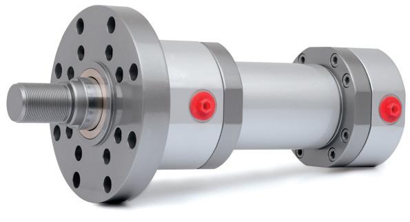
Food and beverage components start their journey with appropriately food-grade materials, such as stainless steel, food-grade polymers and special coatings. 316L stainless steel is known for its ability to resist cor-
PNEUMATICS TECHNOLOGIES ARE USED EXTENSIVELY IN FOOD & BEVERAGE PROCESSING BECAUSE THEY PROVIDE RAPID AND COMPACT ACTUATION WHILE DISCOURAGING THE PROLIFERATION OF HARMFUL CONTAMINANTS.
rosion from acids, cleaning chemicals and the food ingredients themselves. Traditional steel will rust or corrode quickly, shedding contamination into the product while degrading to the point of premature failure.
The stainless construction of air cylinders and motors also ensures the chemicals and hot water (often under pressure) do not damage the actuators or result in rust formation. Between batches or production runs, machines and material handling systems are thoroughly washed down using various caustic, chlorinated or acidic chemicals to prevent microorganism proliferation or to remove residual chemicals for ingredients.
It's possible that pneumatic food production components are made from aluminum or plastics, although the choice of materials must also be suitable for the pro-
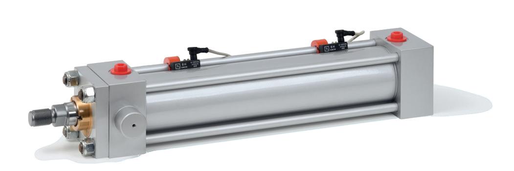
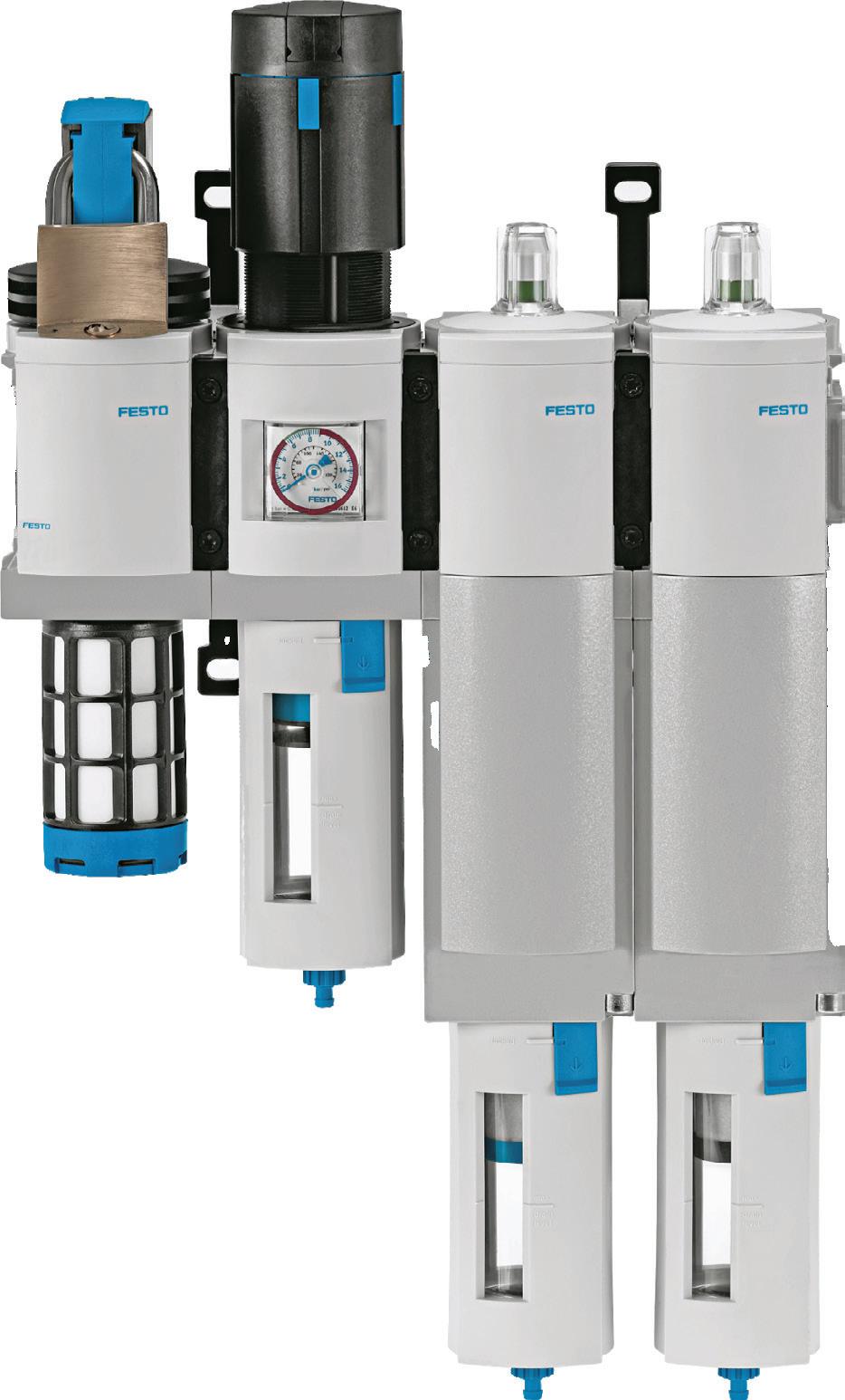
STAINLESS STEEL, ROUND CYLINDERS LIKE SMC’S CF5-S SERIES ARE DESIGNED FOR FOOD PROCESSING TO PROVIDE CORROSION RESISTANCE AND PREVENT RESIDUE BUILDUP FROM SPLASHING OF LIQUIDS.
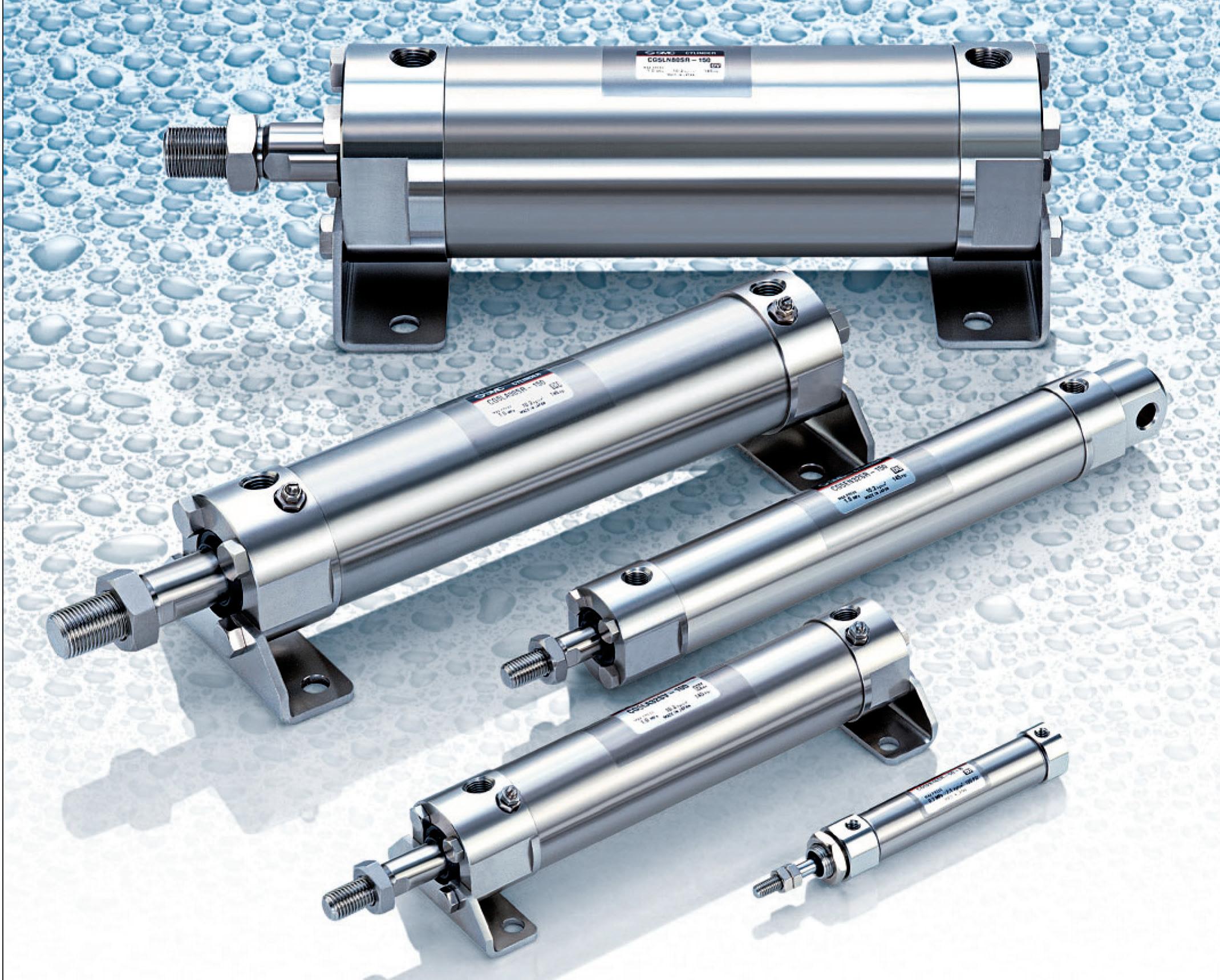
duction environment. Bare aluminum is not suitable and should be either anodized or treated with nickel plating to provide corrosion-resistant protection. When plastics and elastomers are used in food and beverage, such as with fittings, tubes, valves and seals, only FDA-compliant materials like PTFE (Teflon), EPDM, and silicone should be chosen, each of which is superior to other materials at resisting microbial growth while leaching little undesirable substance into the surrounding environment.
Seamless, clean designs reduce risks
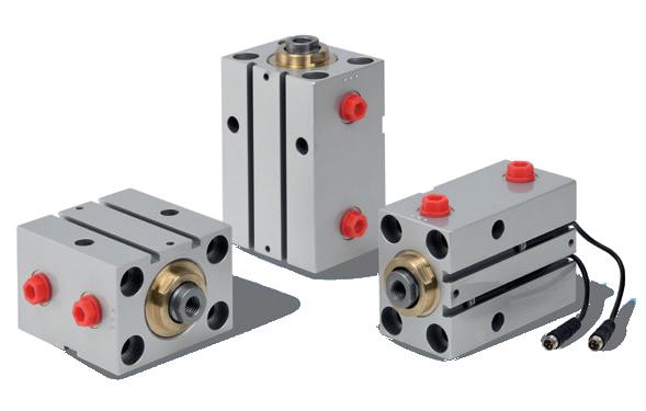
The shape and design of pneumatic parts used in food and beverage should be thoughtfully designed to prevent effective cleaning to prevent the buildup of food ingredients or microbes. Cylinders made from extruded aluminum bodies with compound shapes, including grooves for reed switches, should be avoided for wet applications, as they are difficult to clean effectively. The same goes for die-cast heads and caps that use ribs, ridges or risers for strength, which for food and beverage just provide storage space for previous batches or dangerous bacteria.
Conversely, round body air cylinders with few grooves or crevices are an excellent choice for food and beverage, providing
reliable actuators that are (relatively) inexpensive and easy to clean. If reed switches or position detection is required, sensors can be strapped to the barrel, where a magnetic piston strip can be sensed through the non-ferrous stainless tube.
However, when dealing with dry goods only, the shape of the cylinder is less important. The obvious products here are material handling actuators, such as hopper gate cylinders or Form-Fill-Seal machinery. But many dry goods applications are unique and require specialized equipment.
A Dilute Phase Conveying system, for example, transfers dry goods by first metering the material with a rotary feeder driven by an air motor. The material is then introduced into a compressed air stream, where it sends the material to downstream bins, hoppers or mixers.
Other specialty pneumatic components are used in the storage and handling of food products or ingredients. Air shockers are one such animal and a type of cylinder used only to provide an impact force to dislodge or loosen stuck material. An air motordriven vibrator is frequently used in hoppers and chutes to prevent material from sticking and may remain running throughout the material transfer process. These air vibrators are usually mounted to the outside of
(sqf) GUIDELINES OF FINAL FILTRATION
STAGE 0.01 MICRON AND A PARTICULATE REMOVAL EFFICIENCY OF 99.999% AT THE POINT OF FOOD AND BEVERAGE CONTACT.
the hopper, so their construction material is much less important than those that may be within or near the food product. Some industries, such as dairy, baby formula, nutritional supplements and meat and seafood, may take things a step further with “clean room” level pneumatics. A technique to prevent the introduction of any outside contaminants entering the product is to use vacuum actuators. Although less powerful than pressurized actuators because the best you can hope for is a single bar of pressure the atmosphere provides, a cylinder run by vacuum ensures air is always pulled through the system rather than pushed. Any leaks that may occur will not introduce contamination into the clean room, thereby guaranteeing a pure product despite leaks or failures.
Washdown resistance a must
As mentioned earlier, a consideration with the design of a food and beverage pneumatic component is that it will likely be subjected to a thorough washdown, which is often with hot water and sometimes at high pressure or with chemicals. If there are any electronics in, on or around the machinery, such as pressure switches, solenoid valves or sensors, they must also withstand frequent cleaning sessions.
Expect valves to also be washdown resistant, which means you must look for electrical components IP67 or IP69K rated. The Ingress Protection rating tells you how well the electrical device resists both solids (first number) and liquids (second number). IP67 describes a component that is impervious to solids and may be immersed in water for no less than 30 minutes. IP69K describes a component with the same resistance to solids while also withstanding close-range, high-temperature and highpressure washdowns from various angles.
We can’t describe electronics in pneumatics without also addressing automation. With the proliferation of inexpensive PLCs, sensors and communication protocols, it’s never been easier to automate. Food and beverage is a highly competitive industry producing the same or similar products in many manufacturing plants, and as such, it is ripe for automation.
Although the automation of food and beverage requires no more from the control side not already mentioned, you’d be surprised at the level of sophistication applied to produce 100,000 loaves of bread or bottles of beer every day. Using decentralized control systems connected with one of the various industrial communication protocols such as PROFINET or DeviceNet, plant managers can keep an eye on every step of the process by viewing each substation in real time on one of the various monitors.
Modern pneumatics employ pressure sensors and switches, flow sensors, position sensors (both end-of-stroke and linear transducers) and vacuum switches, and most of these are used in high-volume food and beverage plants. Manufacturers now produce many of their smart sensors with wireless technology, ranging from Wi-Fi to Industrial 5G technology (and, of course, Bluetooth). Even older systems can be upgraded by adding wireless communication modules, providing a network of data that can be col-
lected and trended with software.
The latest in material technology beginning to permeate the food and beverage industry is antimicrobial materials and surface treatments. Although traditional materials such as stainless steel and Teflon have always resisted the adhesion of particles and moisture, increasing the nickel, copper and chromium in either compounds or coatings has added inherent resistance to bacteria and other microorganisms.
One could argue that pneumatics for food and beverage is the most critical application using this form of motivation and power transfer. The world could get by without vehicles, semiconductors and material handling, but without pneumatics to process the vast amount of food and drink humans consume, our population would dwindle rapidly. It’s essential to recognize the unique requirements of this industry so that manufacturers can continue to design and build components that are both sanitary and efficient. FPW
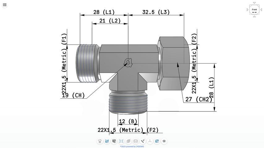
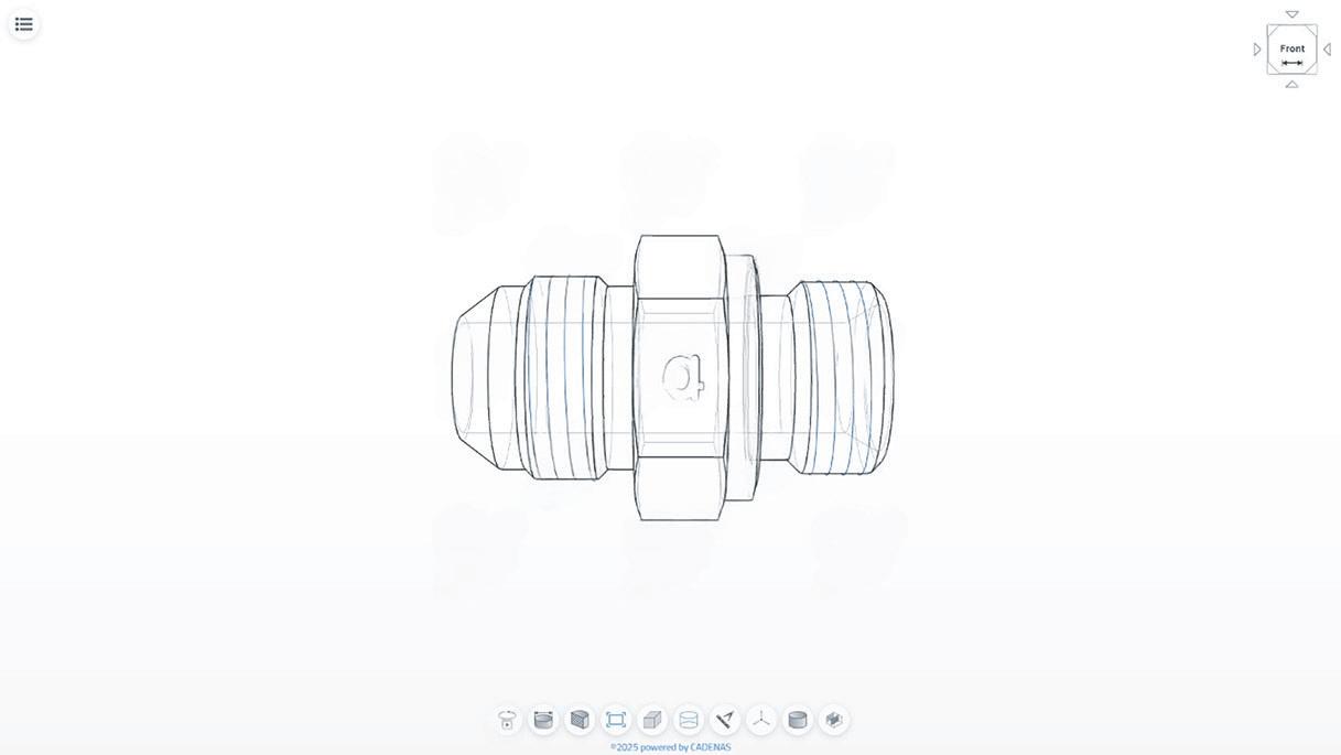
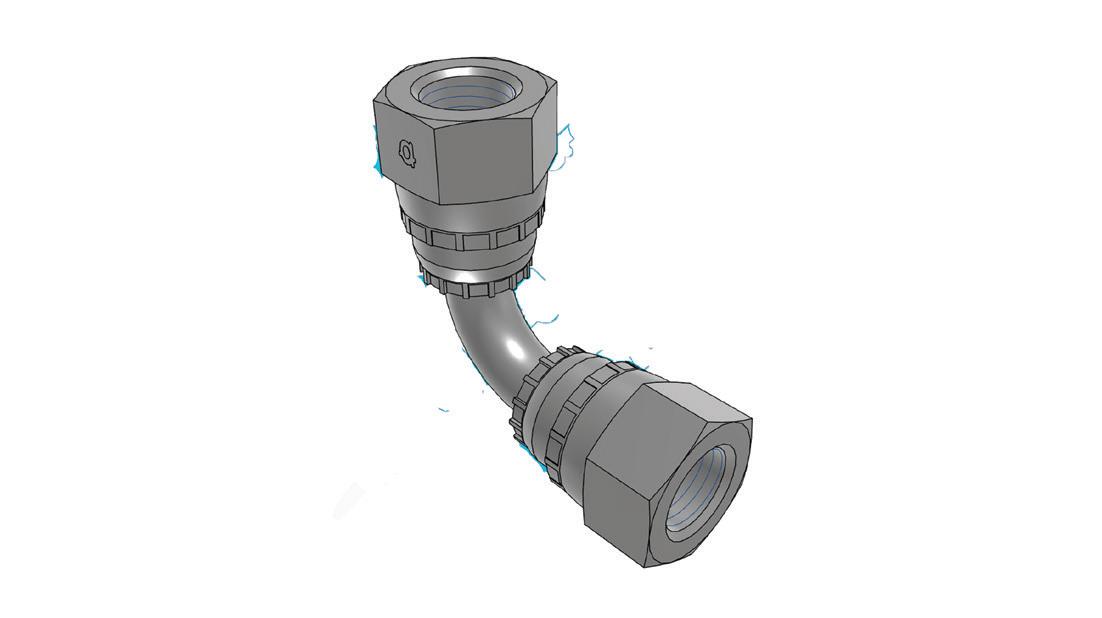
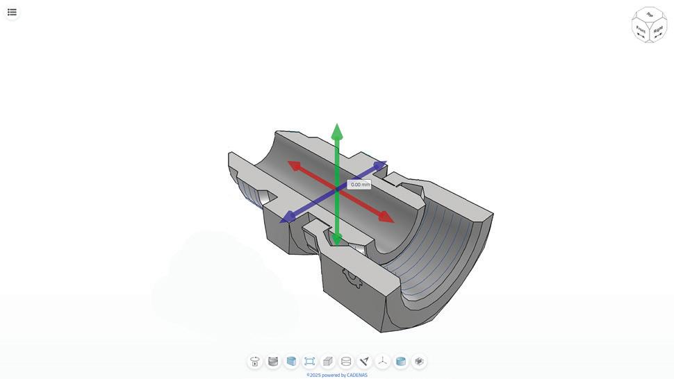
Now on the Adaptall Website, 3D Models are available for all part series!
e have partnered with CADENAS to help bring you 3D models in all of our part families with over 9500 Models to download in over 100 rent for mats!
isit our website for more details!
Italian machine builders are set to showcase their cutting-edge ‘Breaking Necks’ solutions and technologies

Italian machine builders are the key to unlocking your strategic business potential.
How are end users leveraging Italian machinery to advance their operational goals and address significant industry trends? Machines Italia’s Spring 2025 issue will explore key trends across various sectors utilizing Italian machinery, including advancements in automation, environmental sustainability, and the increasing demand for flexible and adaptable machinery. For more details and to read the digital edition, visit machinesitalia.org.


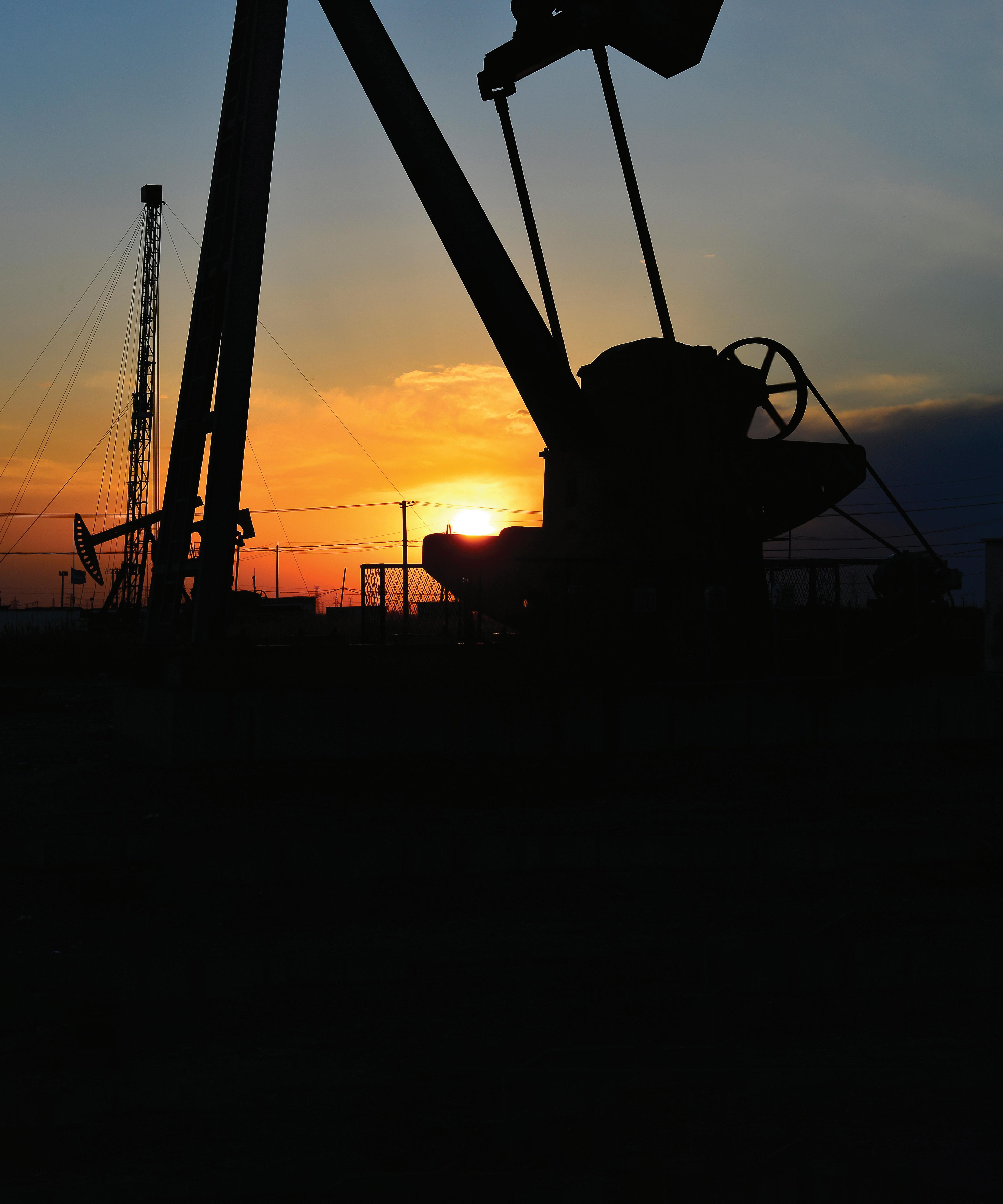
Fluid power manufacturers return to the Offshore Technology Conference in Houston May 5-8 to showcase their durable, reliable and powerful designs.
By Mary C. Gannon, Editor-in-Chief

With a new theme of Waves of Innovation >> Offshore Energy Excellence, OTC will highlight the groundbreaking advancements in offshore energy May 5-8 at Houston’s NRG Park, showcasing the industry's drive for innovation. As global energy needs evolve, Waves of Innovation reflects OTC’s commitment to sustainable, cutting-edge technologies that are shaping the future of offshore energy — from pushing the boundaries of what is possible for oil and gas, to enabling emerging energy sectors like wind and tidal to mature and grow.
At OTC 2025, industry leaders will come together to explore new frontiers in offshore energy, emphasizing the operational efficiency, environmental responsibility, and technical excellence required to meet the challenges of tomorrow’s energy landscape.
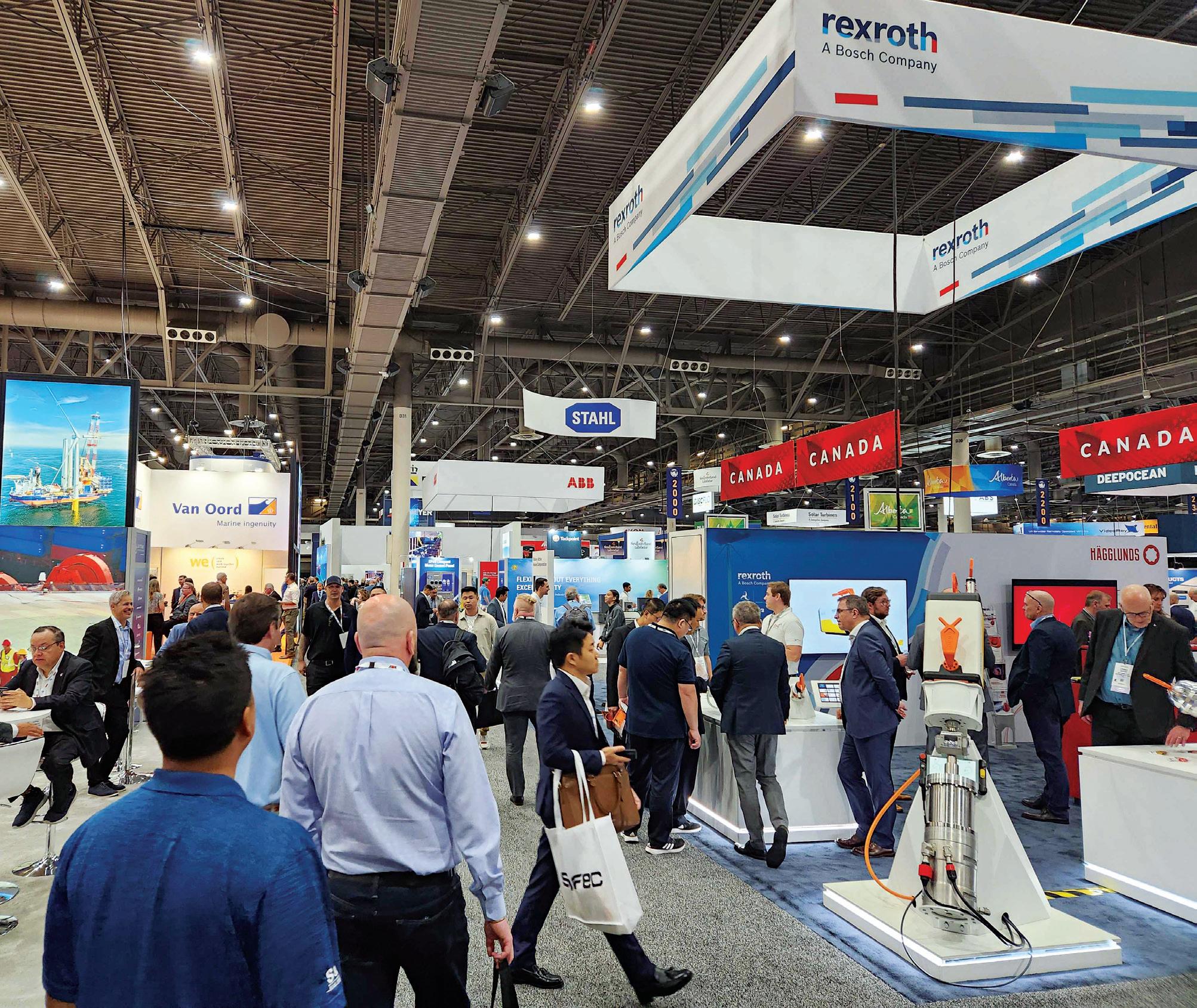
More than 40 fluid power companies will exhibit at the event highlighting the
powerfully dense and safe technologies that encompass hydraulics and compressed air applications.
For fluid power manufacturers, OTC is an opportunity to let users know how they can help them solve their challenges and problems. Hydraulics is ideally suited to the harsh offshore environments of oil and gas where high pressure and corrosive settings reign.
According to Michael Odrzywolski, marketing manager for Moog Inc., “OTC is a chance for Moog to meet customers and companies across the energy and marine industry and listen to the challenges as well as solve problems. People know our reputation for quality and highly reliable technology. Attendees who come to our booth (#1649) will see motors and actuators for
downhole drilling and enabling subsea communication. They’ll see technology that thrives in the harshest environments, in part, because we’ve mastered the science of power/data/fluid transmission. An example of that is our High Voltage Electrical Swivel Joint. HVES enable developers of floating wind energy platforms to commission structures that vertically pivot, or “weathervane,” like the floating production units that process hydrocarbons.”
Likewise, Rota Ltd. will highlight current and new products including its linear and radial transducers for hazardous (European) zone 0/1 suitable for use in North American class 1 division 1 and 2 and safe areas to energy industries for landside, off-shore and subsea applications. Rota will exhibit current and new products at OTC at booth 649. Mike Moore, Technical Sales Engineer, said the company will present its new Rota LA/LO sensors and the small/compact Rota
NM sensor, which is suitable for direct integration into HPU control manifold blocks for safe area deployment. “We also manufacture instrumentation connector and cabling systems for the energy industry too, including live disconnect electrical connectors to mitigate the need for hot permit requirement in hazardous zone 1 areas,” Moore said. “Energy applications include all landside drill rig-floor functions, pipe handling, valves, chokes, wellhead latches and BOPs. Off-shore and subsea applications include all drill rig-floor functions, pipe handling, chain jacks, valves, wellhead latches, BOPs, PLET/PLEM and ROV.”
System Seals will be exhibiting at OTC in booth 629 for the first time, said Matt Zalick, director of business development. The company will be highlighting its capabilities, custom design and R&D for subsea projects and will be focusing on seals designed specifically for oil and gas.
“In the oil and gas space we've developed some new sealing profiles that are specifically designed to retrofit seals in the pressure controls group,” Zalick said. “These systems were largely designed with that we would call standard catalog seals. There are some prominent players out there that are speccing the same seals in subsea equip-
ment, that they also put in hydraulic cylinders going on excavators and in steel mills. But we have a sealing set that is specifically designed for retrofitting in this subsea equipment. Those seals are made from materials that are also specifically designed for managing the different fluids, pressures and temperatures found in those applications. There's a specialty material that we use as an anti-extrusion device in these seals — our code L120 — that is a an engineered polymer that replaces PEEK material, which tends to drive up cost in subsea seals. That's the material we make here at system seals.”
One of the key highlights at the igus booth 3565 will be its e-loop, a modular e-chain cable carrier that ensures the safe and reliable guidance of cables and hoses in dynamic hanging applications such as top drive systems in drilling rigs, construction machines, oil platforms, and wind turbines. The e-loop is a finalist for ASME’s Best Mechanical Engineering Achievement (bmea) Award. Winners will be announced at OTC. Igus will also be highlighting its array of motion plastics technologies, including
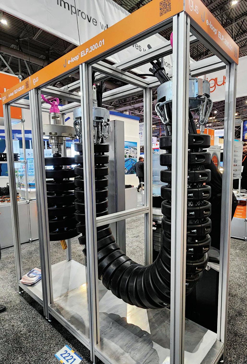
e-chains, bearings, cables and more.
Like the industrial manufacturing and mobile machinery industries, electrification, smart technologies, hydrogen, and AI are also taking offshore by storm and will be seen throughout the conference program. As the industry has evolved so have the topics. Many of them include alternative energy production as well as sustainability functions for offshore drilling. Such topics will include the following:
• Driving Efficiency and Innovation in Offshore Production Through Electrification
• Intelligent Solutions and Technologies in Well Design, Completion, Productivity and Subsea Operations
• Optimizing Drilling and Monitoring Through Innovations in Digitization, AI, and Machine Learning
• Hydrogen in the Marine Environment: Applications and Safety
• Digital Transformation of the Offshore Energy Industry
Several of the technical sessions will also be covering alternative energy production where wind and hydrogen will be major players. FPW
ElGi Equipments Ltd. elgi.com
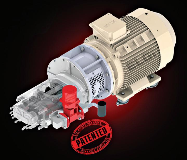
Stabilsor compressed air stabilization technology addresses the long-standing challenges of unstable compressor performance, inefficiency, and excessive wear caused by frequent load/unload cycles. In industrial settings, the gap between compressor capacity and plant air demand is inherently dynamic. This variability leads to frequent cut-in and cut-out operations, which destabilize the compressor and impair critical flow and kinematic components. The Stabilisor system employs a “recirculate and recover” principle, seamlessly aligning compressor capacity with plant air demand through controlled recirculation and recovery techniques. By stabilizing airflows within the system, it minimizes load/unload cycles, ensuring extended equipment lifespan, optimizing energy use,and achieving up to 15% energy savings, while reducing system inefficiencies. A light version is designed for field fitment, energy savings and enhanced reliability while the heavy version is factory-fitted for superior energy savings and comprehensive stability.
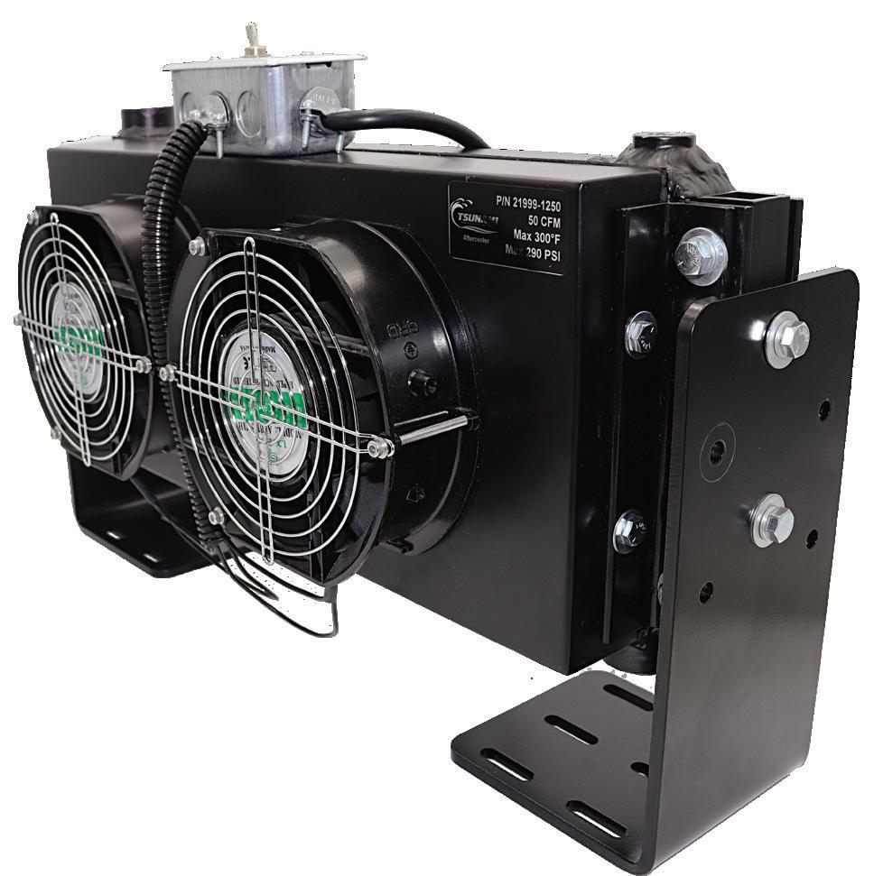
Tsunami Compressed Air Solutions tsunami.us.com
Tsunami Aftercooler is a high-performance solution designed to pre-cool compressed air before it reaches the downstream equipment, maximizing moisture removal and improving system efficiency. With six versatile mounting configurations, a space-saving wall-mounted design, and a powerful cooling system featuring a high-volume fan and finned copper coil, the After cooler enhances air quality, reduces maintenance costs, and extends equipment life. It ensures reliable compressed air perfor mance while minimizing downtime and operational disruptions.
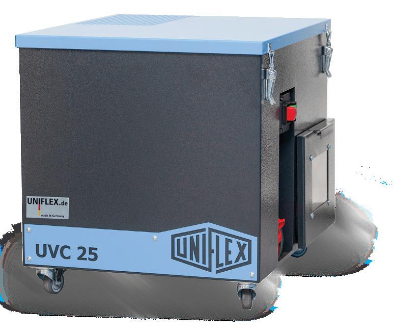
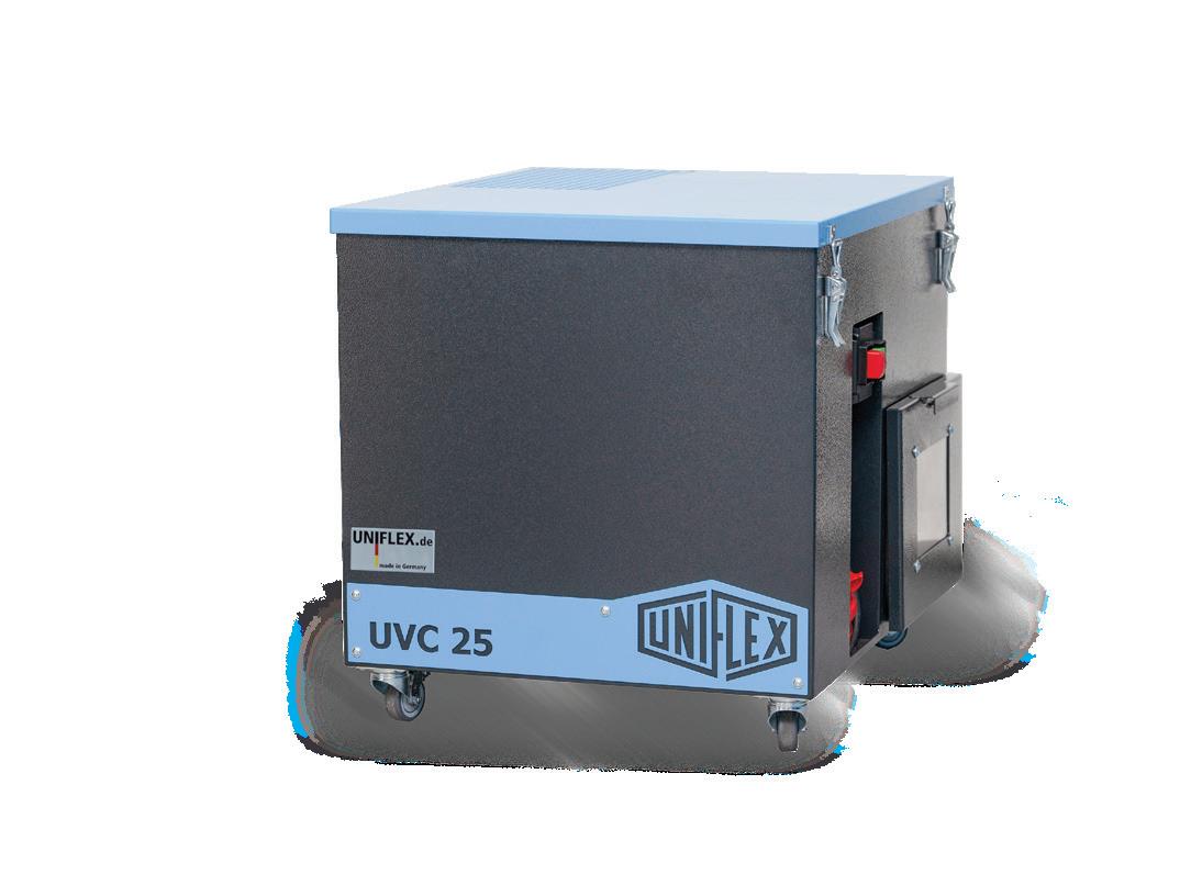
UNIFLEX uniflex.de
New UVC 25 compact and high-performance extraction system is designed specifically for small workshops. The UVC 25 is the perfect complement to hose cutting machines, seamlessly fitting into the UNIFLEX TU standard table with its compact dimensions of 600 x 570 x 555 mm. With a drive power of just 0.95 kW, the UVC 25 delivers a suction capacity of 100 m³/h. Despite its high air performance, the system operates at a quiet 60 dB(a) — comparable to the noise level of a coffee machine — ensuring it does not disrupt the workday. The UVC 25 ensures clean, dust-free air during cutting processes, contributing to a safe and comfortable working environment. Equipped with a multi-stage filtration system, the UVC 25 offers maximum air purification with an activated carbon filter to eliminate unpleasant odors.
Parker Hannifin parker.com
The Hydraulic Valve Systems Division of Parker Hannifin launched its DFplus Generation IV proportional valves with fundamentally revised electronics. This expands its communication capabilities and improves connectivity for demanding industrial applications. Mechanical components such as its patented voice coil drive (vcd) remain largely unchanged. A new dual core processor enables them to run at maximum performance level and to communicate with the PLC simultaneously. An integrated near-field communication (nfc) chip allows users to obtain all status information in the field or in service situations — even when the valve is not actively powered. A 360° LED at the top of the electronics box ensures that the basic status data is immediately visible in the application by different colors or flashing frequencies.
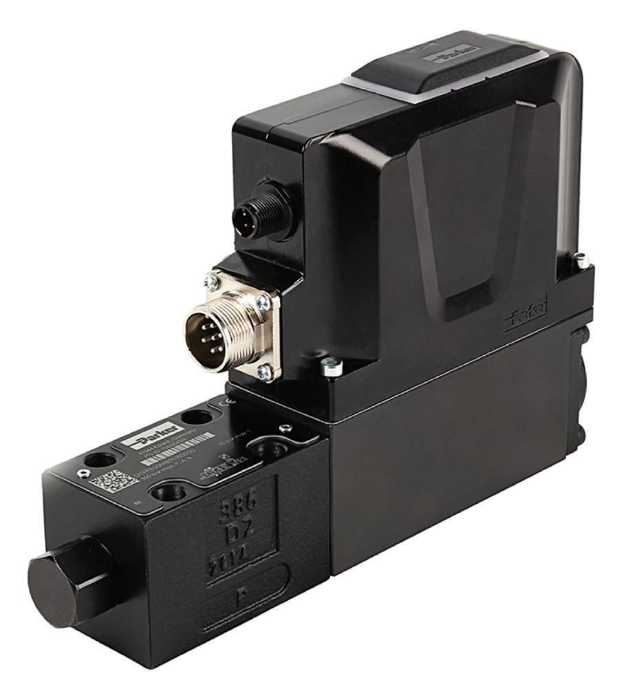
Danfoss Power Solutions danfoss.com
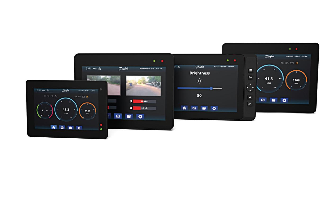
DM-Qt series programmable displays support Qt as a plug-in to PLUS+1 GUIDE, where user interface (ui) design can be developed through the Qt framework — the new standard in the automobile industry. Qt enables displays to be programmed faster and reduces time to market. Qt tools enable reuse of templates across multiple device platforms and display brands. DM-Qt displays enable graphical development in Qt Design Studio. Application programming is managed in Danfoss’ PLUS+1 GUIDE software. Displays are available in 7-, 10-, and 12-in. displays, with features such as outstanding sunlight and wide-angle viewability, automatic brightness adjustment, superior touch responsiveness, and rugged design with high ingress protection ratings.
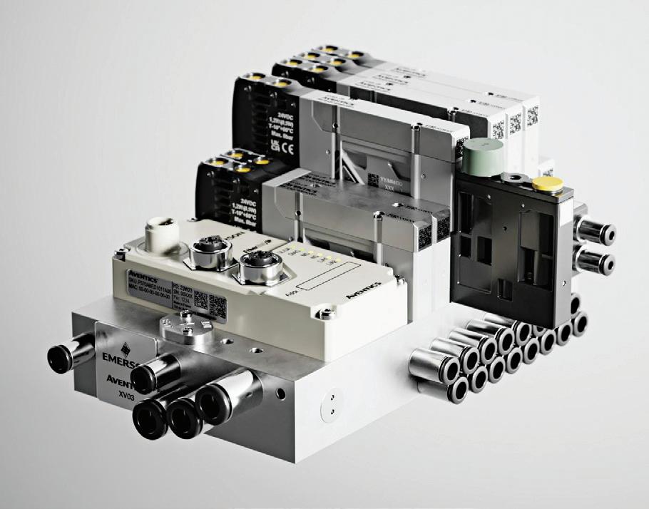
Next-generation Aventics XV03, larger series XV05 and bottom-ported version of the XV03 pneumatic valve systems feature new flow rates, configurations, accessories, UL certifications and more. The XV03 provides flow volumes up to 350 lpm in normal conditions (NL/min), and the XV05 provides up to 1000 NL/min. Both comply with UL429 and UL61010 for quality and safety. New and existing accessories provide greater functionality and include separators, blank stations, pressure supply plates, sandwich pressure supply, and sandwich pressure exhaust. A custom toolbox contains the most important tools to assemble XV systems. The valves include metal threads, aluminum base plates and compact dimensions to make integration easier.
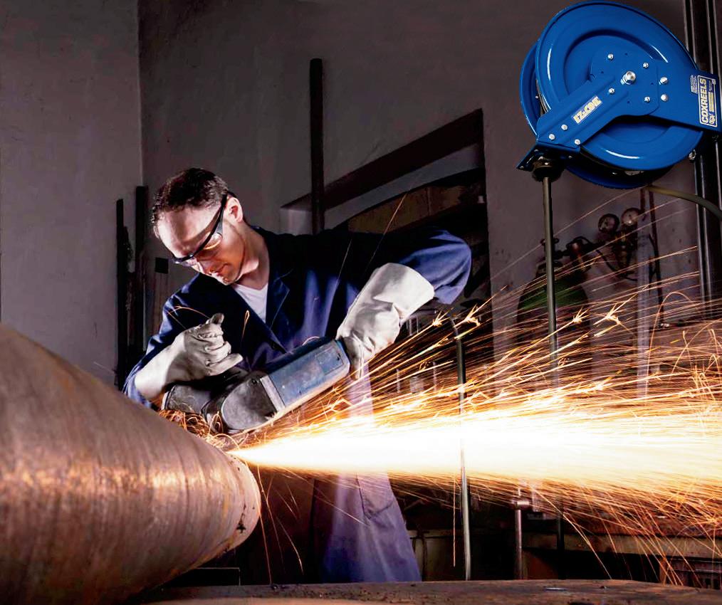
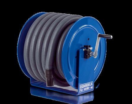
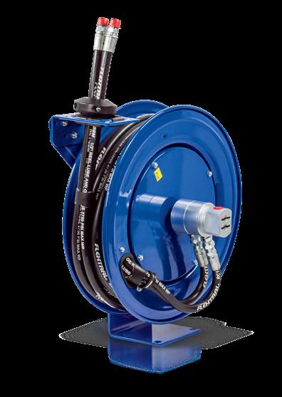
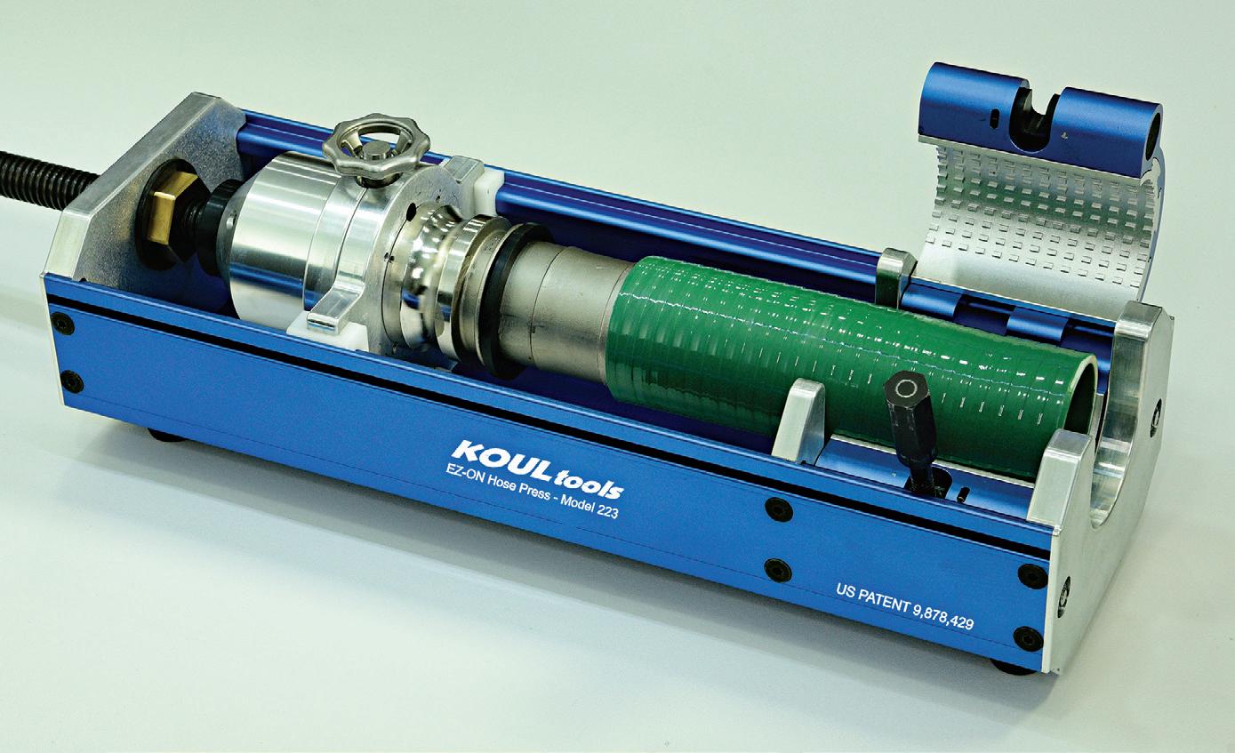
Koul Tools koultools.com
EZ-ON Hose Press Model 223 installation tool for 2-3 in. industrial, hydraulic, and agricultural hoses features a robust lead screw system with a 6:1 gear reduction drive and a newly designed, patent pending fitting holder. The 223 model is operated by a batterypowered impact gun, facilitating on-site installations while ensuring ergonomic efficiency. The EZ-ON Hose Press 223 is constructed of aluminum and stainless-steel parts, making it durable but also lightweight to transport to and from job sites and comes with a custom case. The easy-to-use clamping systems for the hose and the fitting give you fast, hassle-free installations. FPW


Robert Sheaf • Founder of CFC Industrial Training
I WAS RECENTLY CALLED BY A CUSTOMER who attended one of our advanced hydraulic training sessions. He was having a problem with an old rolling mill.
The servo-controlled cylinder that held position on one of the rolls was oscillating. This cylinder helped maintain the thickness of the sheet steel they produce. He said it seemed like it was having problems finding and maintaining its position.
He sent us the attached circuit drawing made by a local hydraulic shop that he deals with for repairs and service. It was a handdrawn sketch that we redrew for this article.
He had replaced the Moog servovalve, replaced the filter elements and the electronic position feedback sensor. We asked him if there was any work done before this problem showed up. He informed us that they replaced a leaking steel tube and its fitting on the cap end of the cylinder with a new hose.
What would you do next? We welcome responses of all kinds directly to Bob Sheaf at rjsheaf@cfc-solar.com or to mgannon@wtwhmedia.com The solution will be provided in conjunction with next edition of Fluid Power World and will be published online in March.
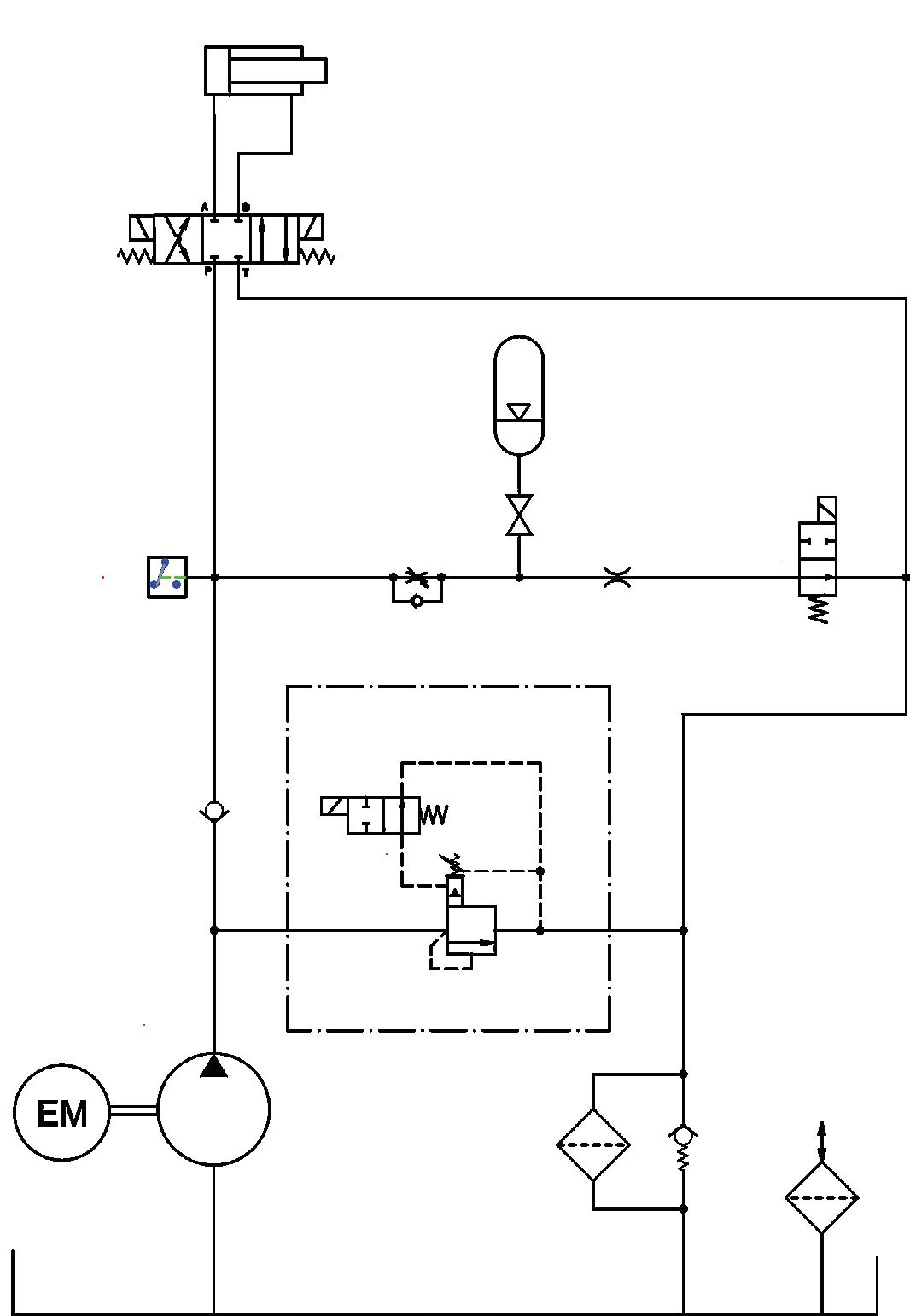
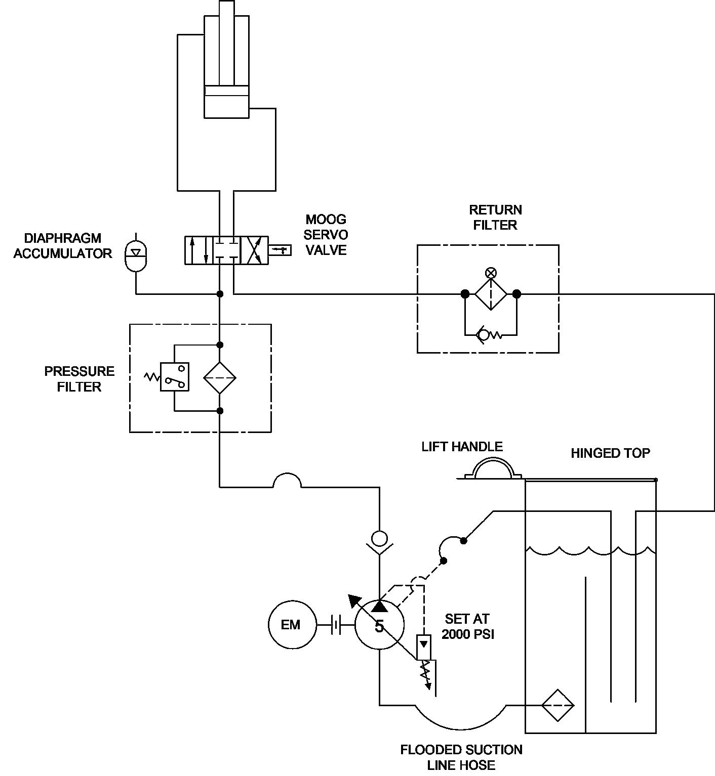
The sequencing of the hydraulic circuit powered up both 2-position directional valves simultaneously, allowing pressure to build up, thus filling the accumulator. When the pressure switch setting was reached, the main, 3-position directional valve was used to load, and lift the steel plate being bent. During idle, if the pressure switch was still tripped, the system relief valve solenoid was de-energized allowing the pump to idle at a very low pressure.
The problem they were having was caused by the absence of the orifice located between the accumulator and the new valve they installed. The orifice allowed the accumulator to bleed down slowly at a low flow rate during power-down. Excessive flow from the accumulator discharging unrestricted caused over-pressure at the inlet of the filter and aeration of the fluid. The bleed down orifice might be in several different places. This orifice was a “port insert” and originally located in the pressure port of the old 2-position directional valve and discarded. They retrieved the old valve, removed it, and installed the orifice in the new valve’s “P” port, and re-installed the return filter. FPW