


www.fluidpowerworld.com April 2023 Making sense of hydraulic manifold mazes p. 28 Get a grip with modular vacuum kits p. 32 Optimized sealing for offshore wind p. 36 goes CONEXPO PAGE 44 electric


www.fluidpowerworld.com April 2023
manufacturing at the local level.
: Indiana has been our home for manufacturing since 1985. We also have an office in Texas, and a new building is being erected for our existing Florida location. Our manufacturing base will always be in the US.
Sourcing domestically: We prioritize other domestic manufacturers and suppliers when sourcing components for our products.


Educating students: It’s not just producing tools in the here and now. Today’s students should be exposed to all elements of the manufacturing process and how to apply them, not just the last few steps of assembly.
We’ve started by sponsoring capstone projects at Purdue University and will be offering demonstration kits to schools interested in teaching students about electropneumatic control.


The US has a long history of manufacturing products from start to finish. From early immigrants setting up textile factories, sawmills and glassworks to the automotive boom of the 20th century, there is no question of our capabilities. It’s in our hands to support domestic products.
Join us in Retooling America.

“Retooling
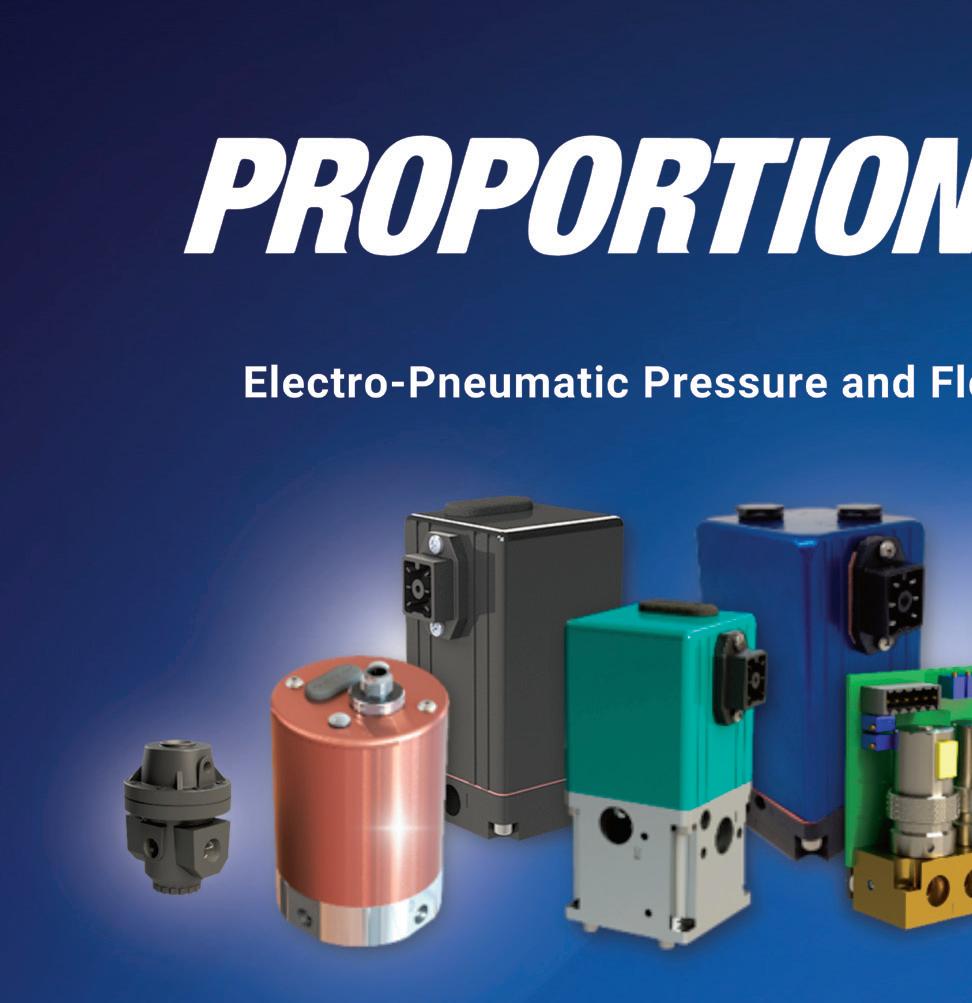
Accurate, repeatable, customizable electro-pneumatic control to get the most out of your compressed air or compressed gas applications. Phone: 317-335-2602 Live support, M-F 8 a.m. - 6 p.m. ET. www.proportionair.com info@proportionair.com Ready to Learn More?
America”?

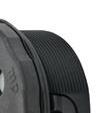
PROTEC NYLON HOSE SLEEVE tompkinsind.com/NHS 800.255.1008
NEW! More Murrplastik Cable Entry System Options...


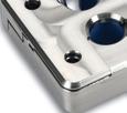
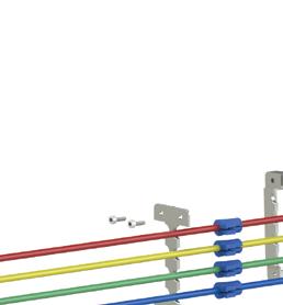
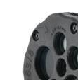
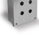
Murrplastik cable entry systems allow installation of non-terminated or pre-made/terminated cables through an enclosure or other bulkhead surface. Our new additions include:


• The KDP/R series: A round one-piece frame available in two different frame sizes that can hold up to 46 non-terminated cables in a single frame.

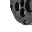

• FDA compliant cable entry systems ideal for food, beverage, pharmaceutical, and any industry requiring sanitary components.


–KDL/H-VA-FDA series: Stainless-steel split frames, available in three sizes that can hold up to 12 pre-made or terminated cables.


–KDP series FDA Cablequick® system: A one-piece stainless-steel frame that can hold up to 56 non-terminated cables.


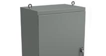
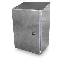
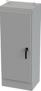
the #1 value in automation Order Today, Ships Fast! * See our Web site for details and restrictions. © Copyright 2022 AutomationDirect, Cumming, GA USA. All rights reserved. 1-800-633-0405 Research, price, buy at: www.automationdirect.com/enclosures Over 7,100 top brand enclosures starting at only $7.00 • Wall-mount • Junction boxes • Pushbutton • Floor-mount • Freestanding • Modular • Desktop workstations • Various types of metallic and non-metallic constructions • And much more... • Disconnect • Internal mount disconnects • Consoles and consolets • Wire troughs We o er a full line of quality enclosures from the best manufacturers in the world Plus over 5,800 low-cost accessories and wiring solutions for those all-important nishing touches!
KDP Series KDP/R Series Note: Mounting Hardware not included. KDL/H-VA-FDA Series
FLUIDLINES
Mary C. Gannon • Editor-in-Chief
IFPE is proof positive that
our industry is flourishing
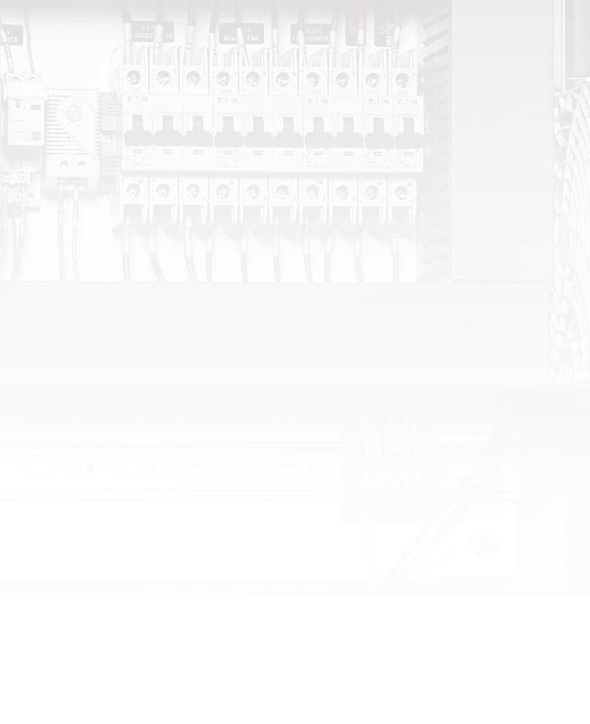
My big takeaway after 2-½ days on the IFPE show floor (plus a couple of hours on the CONEXPO-CON/AGG lots), was simply, WOW. The energy and vibe that lived in the South Hall last month was electric (pun intended, with all the talk about mobile electrification). Companies and individuals were thrilled to be together again, and it showed.
The show hit record numbers, drawing more than 139,000 construction and fluid power professionals from 133 countries to Las Vegas — making it the largest trade show in North America with roughly 2,400 exhibitors from 36 countries spread out over 3 million square-foot of exhibit space.
The number of folks that stopped me in the aisles to say hello, offer compliments on all the great work Fluid Power World is doing, or just to introduce themselves was amazing. I have never received so many hugs on a trade show floor before in my life — clearly, everyone was thrilled to be together again, and it showed. There has been talk off and on the past three years that maybe we didn’t need trade shows or in-person calls. IFPE squashed all those thoughts with the exuberance of a toddler on Christmas morning.
And clearly, fluid power manufacturers were busy over the past three years. Although they’ve spent a lot of time catching up on perhaps the busiest times in their businesses as they dealt with high orders and supply chain crunches, the innovations didn’t disappoint.
We’ve been covering all those product innovations here in our Fluid Power network of websites — mobilehydraulictips.com, fluidpowerworld.com, hoseassemblytips.com, sealingandcontaminationtips.com, and pneumatictips.com (where relevant). Stay tuned for our post-show wrap-up videos as well, where we’ll talk about some of the coolest tech we each saw — note, you’ll see a lot of discussion about sustainability, efficiency, electrification, digitalization, and autonomy and automation.
Watch out next month, too as we compile all these stories and new product releases into a special digital-only post-IFPE issue. Here, you’ll see additional reviews of systems and technologies that create functionally safe, efficient, and reliable machines that can be powered by diesel engines, electric-hybrid, and all-electric designs. In this issue, Ken Korane takes a look at some of the machines he saw out on the CONEXPO lots (page 44), and he’ll dive further into additional machinery in May.
If time allowed, we would have visited every hydraulics manufacturer on that show floor. But one thing I noticed when I cruised by booths is that they were always busy — and while it’s great to catch up with our friends in the industry, meeting their current and potential clients is more important than ever. So please do reach out if we missed you and you have new technology to share. We’ll continue to work on post-IFPE updates for the next several weeks.
The next CONEXPO-CON/AGG & IFPE will be held March 3-7, 2026, at the Las Vegas Convention Center. We’ll see you there. In the meantime, keep reading! FPW
Mary C. Gannon • Editor-in -Chief mgannon@wtwhmedia.com


2 FLUID POWER WORLD 4 • 2023 www.fluidpowerworld.com
On Twitter @FPW_marygannon


3410 Delta Drive • Portage, IN 46368 • Tel: (219) 762-2059 • Fax: (219) 762-2066 • www.alaindustrieslimited.com 243 MILLION DRIVERS IN THE U.S. trust Yuken hydraulic components with their lives every day! Whether you’re taking the kids to soccer practice, or operating a compactor, Yuken has your back! ALA Industries Limited
Rachael Pasini • Senior Editor
An exciting time for fluid power
I don’t know if it was the Las Vegas rain or the underground Tesla shuttles, but IFPE 2023 felt like an alternate reality. With more than 1,800 exhibitors spanning 2.8 million square feet, the joint CONEXPO-CON/AGG and IFPE event was larger than life and full of energy, technology, and — best of all — people.
Industry experts from around the world celebrated innovation and introduced new products that help engineers solve today’s problems and work toward sustainability goals. Though electrification won the homecoming crown this year, hydraulics will surely remain in the court for decades.
Now, that doesn’t mean fluid power technology will stay the same. Every IFPE booth I visited demonstrated that the industry is experiencing a mindset shift. People are thinking differently about problems and how the problems are changing. No one’s trying to reinvent the wheel, but engineers are working on practical innovations that help move the needle and address tomorrow’s concerns.
Zero-emissions was a hot topic during press conferences and casual lunchtime chatter, yet there’s still confusion about what “net zero” really means. Because this ambition seems relatively abstract and far away, many OEMs are breaking up the lofty, longterm goal into attainable, short-term targets. For instance, Terex reiterated its commitment to a 15% reduction in greenhouse gas emissions by 2024, and more than 60% of its current solutions are already electric or hybrid. Similarly, JCB’s “Road to Zero” can be traced back to 2004 with its incremental progress of reduced-emission engines to its present-
day hydrogen combustion engines and mobile hydrogen-powered machines.
Coinciding with environmental goals, companies are reshoring operations and investing more in their supply chains. They’re planning to bring production closer to key customers and rethinking their entire manufacturing processes and technologies — perhaps a silver lining from the COVID-19 pandemic.
For example, Aidro has been machining hydraulic valves and manifolds since 1982. As of 2017, the Italian company has invested in additive manufacturing to design and produce 3D-printed components with complex geometries. In 2021, Aidro joined Desktop Metal to produce intricate hydraulic parts that cannot be crafted with other methods.
Walking booth-to-booth, I discovered that many fluid power manufacturers and OEMs are quietly adopting 3D printing where it makes sense. Though shy with details for fear of revealing a competitive
advantage, whenever I pointed to a product on display and asked, “Is this one 3D printed?” I often received a smile and brief confirmation that the company is using additive technology to expand product offerings and gain more control over its production.
Overall, IFPE showed that it’s an exciting time to be in the industry. All this change forces engineers to approach challenges in new ways that chart paths toward more sustainable futures. I look forward to returning in 2026 to see how things evolve and reacquaint with my new fluid power friends. FPW


 Rachael Pasini Senior Editor rpasini@wtwhmedia.com On Twitter @WTWH_Rachael

PERSPECTIVES
4 FLUID POWER WORLD 4 • 2023 www.fluidpowerworld.com


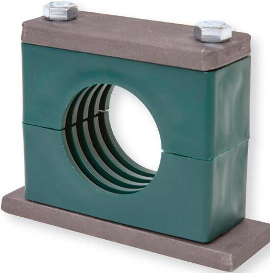

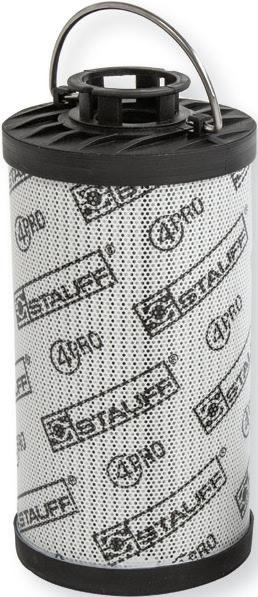


Contributing to Your Success STAUFF Corporation 201.444.7800 STAUFF Canada Ltd. 416.282.4608 stauffusa.com We offer thousands of critical components designed to help our customers operate more efficiently. Look to STAUFF for Quick Couplings, Clamps, Hydraulic Filters, Test Points and many other components to keep machines—big and small—moving you forward. Contributing to Your Success
FEATURES
MANIFOLDS
Making sense of hydraulic manifold mazes Learn how three manifold designs — the common hydraulic integrated circuit, stackable bar designs, and simple passageways for pressure or return — are manufactured for hydraulic designs.
PNEUMATICS
Get a grip with modular vacuum kits
Vacuum gripper technologies provide many advantages for machine and OEM payload handling. Designers find that modular gripper system kits are a versatile and rapid way to create handling solutions, with other benefits such as internal vacuum routing.

OFFSHORE WIND SEALING
Maximizing wind turbine efficiency through optimized hydraulic sealing Advanced seal designs that prevent wear, increase service life, and reduce friction can ensure uptime in pitch cylinders and brakes.

OTC PREVIEW
OTC hones in on modern offshore tech

The Offshore Technology Conference returns May 1-4 at NRG Park in Houston.

MOBILE HYDRAULICS
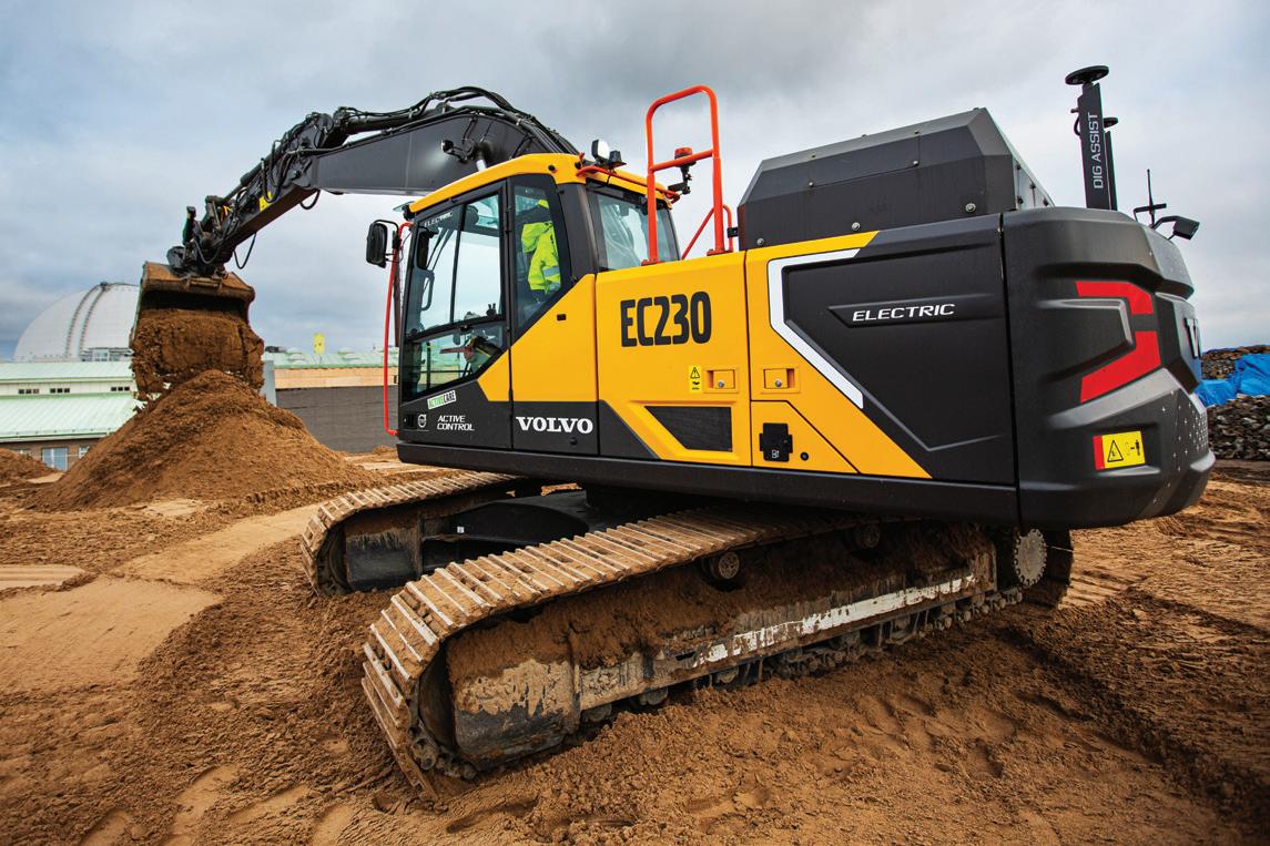
CONEXPO goes electric A wave of battery powered machines is set to move out of the R&D labs and onto construction sites.
28 32 36 42 44

APRIL 2023
Contents | vol 10 no 3 | fluidpowerworld.com • 4 • 2023 ON THE COVER A wave of electrified machines is flowing into construction sites, like the mid-size EC230E battery-electric excavator. | Courtesy of Volvo CE DEPARTMENTS 02 FluidLines 04 Perspectives 10 Design Notes 18 Maintenance 20 Fundamentals 22 Component Focus 24 Association Watch 26 Energy Efficiency 51 Products 55 Ad Index 56 Troubleshooting Challenge 6 FLUID POWER WORLD 4 • 2023 asbpe.org BRONZE REGIONAL AWARD 2023 asbpe.org BRONZE REGIONAL AWARD 2023
•
Check
•
• Industrial
• Mining
• Forestry
• Medical
• Aerospace
• Factories
• Mobile Equipment

• Defense


• Machine Tool
• Testing Equipment
• Ocean Depth Technology


• Automotive
• Food Processing
• Agriculture
• Industrial
• Aviation
• Petrochemical
• Marine
• Subsea

Served:
Industries
Oil & Gas
Hydraulics
Processing Plants
Chemical & General
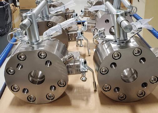
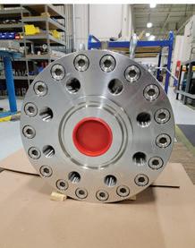
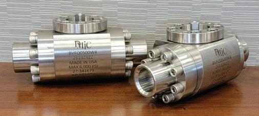
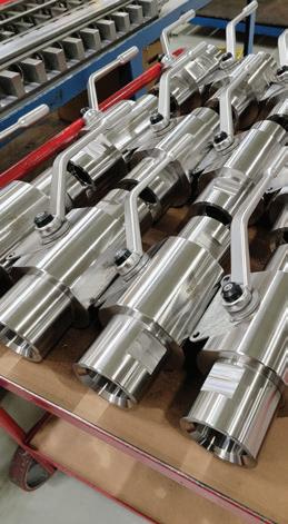
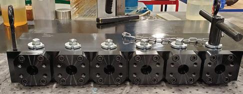
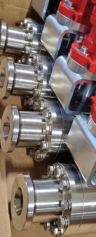
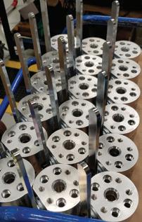
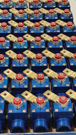
DELAWARE MANUFACTURING INDUSTRIES CORPORATION Solutions Under Pressure ISO 9001 Certified Medium - High Pressure Valves Low Pressure Suction Valves Subsea & Gas Valves Specialty Valves 800.248.DMIC (3642) • WWW.DMIC.COM • SALES@DMIC.COM Made In America Manifold Mounted Valves Manifolds
Valves
Ball
Valves
Valves
Flow Control
Needle Valves Flanges & Adapters
Bar & Custom Manifolds
Pressure Gauges & Snubbers
SSW Power Unit Systems
Transfer Pumps
Don’t compromise!
MARKETING
VP, Digital Marketing Virginia Goulding vgoulding@wtwhmedia.com @wtwh_virginia
Digital Marketing Manager Taylor Meade tmeade@wtwhmedia.com @wtwh_taylor
Digital Marketing Specialist Shannon Pipik spipik@wtwhmedia.com @WTWH_Shannon
PRODUCTION SERVICES
Customer Service Manager Stephanie Hulett shulett@wtwhmedia.com
Customer Service
Representative Tracy Powers tpowers@wtwhmedia.com
Customer Service Representative JoAnn Martin jmartin@wtwhmedia.com
Senior Editor Rachael Pasini rpasini@wtwhmedia.com
Associate Editor Heather Hall hhall@wtwhmedia.com @wtwh_heathhall
Contributing Editor Josh Cosford @FluidPowerTips
Contributing Editor Carl Dyke @carlindustry
Contributing Writer Robert Sheaf rjsheaf@cfc-solar.com

PRINT PRODUCTION
VP, Creative Services Mark Rook mrook@wtwhmedia.com @wtwh_graphics
VP, Creative Services Matthew Claney mclaney@wtwhmedia.com @wtwh_designer
Art Director Allison Washko awashko@wtwhmedia.com @wtwh_allison
Senior Graphic Designer Mariel Evans mevans@wtwhmedia.com @wtwh_mariel
Director, Audience Development Bruce Sprague bsprague@wtwhmedia.com
VIDEO SERVICES


Videographer Garrett McCa erty gmccafferty@wtwhmedia.com
Videographer Kara Singleton ksingleton@wtwhmedia.com
www.nfpa.com


Digital Production/ Marketing Designer Samantha King sking@wtwhmedia.com
Marketing Graphic Designer Hannah Bragg hbragg@wtwhmedia.com
Webinar Manager Matt Boblett mboblett@wtwhmedia.com

Webinar Coordinator Dan Santarelli dsantarelli@wtwhmedia.com
ONLINE DEVELOPMENT & PRODUCTION
Web Development Manager B. David Miyares dmiyares@wtwhmedia.com @wtwh_webdave
Senior Digital Media Manager Patrick Curran pcurran@wtwhmedia.com @wtwhseopatrick
Front End Developer Melissa Annand mannand@wtwhmedia.com
Software Engineer David Bozentka dbozentka@wtwhmedia.com
Digital Production Manager Reggie Hall rhall@wtwhmedia.com
Digital Production Specialist Nicole Lender nlender@wtwhmedia.com

Digital Production Specialist Elise Ondak eondak@wtwhmedia.com
Digital Production Specialist Nicole Johnson njohnson@wtwhmedia.com
Customer Service Representative Renee Massey-Linston renee@wtwhmedia.com
Customer Service Representative Trinidy Longgood tlonggood@wtwhmedia.com
IN-PERSON EVENTS
Events Manager Jen Osborne jkolasky@wtwhmedia.com @wtwh_jen
Events Manager Brittany Belko bbelko@wtwhmedia.com
Event Marketing Specialist Olivia Zemanek ozemanek@wtwhmedia.com
FINANCE
Controller Brian Korsberg bkorsberg@wtwhmedia.com
Accounts Receivable Specialist Jamila Milton jmilton@wtwhmedia.com
SALES
Ryan Ashdown 216-316-6691 rashdown@wtwhmedia.com
Jami Brownlee 224.760.1055 jbrownlee@wtwhmedia.com
Mary Ann Cooke 781.710.4659 mcooke@wtwhmedia.com
Jim Powers 312.925.7793 jpowers@wtwhmedia.com @jpowers_media
Courtney Nagle 440.523.1685 cseel@wtwhmedia.com @wtwh_CSeel
FLUID POWER WORLD does not pass judgment on subjects of controversy nor enter into dispute with or between any individuals or organizations. FLUID POWER WORLD is also an independent forum for the expression of opinions relevant to industry issues. Letters to the editor and by-lined articles express the views of the author and not necessarily of the publisher or the publication. Every effort is made to provide accurate information; however, publisher assumes no responsibility for accuracy of submitted advertising and editorial information. Noncommissioned articles and news releases cannot be acknowledged. Unsolicited materials cannot be returned nor will this organization assume responsibility for their care.
FLUID POWER WORLD does not endorse any products, programs or services of advertisers or editorial contributors. Copyright© 2023 by WTWH Media, LLC. No part of this publication may be reproduced in any form or by any means, electronic or mechanical, or by recording, or by any information storage or retrieval system, without written permission from the publisher.
SUBSCRIPTION RATES: Free and controlled circulation to qualified subscribers. Non-qualified persons may subscribe at the following rates: U.S. and possessions: 1 year: $125; 2 years: $200; 3 years: $275; Canadian and foreign, 1 year: $195; only US funds are accepted. Single copies $15 each. Subscriptions are prepaid, and check or money orders only.
SUBSCRIBER SERVICES: To order a subscription please visit our web site at www.fluidpowerworld.com


APRIL 2023 • vol 10 no 3 • www.fluidpowerworld.com 2011- 2020
FLUID POWER WORLD (ISSN 2375-3641) is published eight times a year: in January, February, April, June, July, August, October, and December by WTWH Media, LLC; 1111 Superior Ave., Suite 2600, Cleveland, Ohio 44114. Periodicals postage paid at Cleveland, OH & additional mailing offices.
Send address changes to: Fluid Power World, 1111 Superior Ave., Suite 2600, Cleveland, OH 44114 2013- 2017 2014- 2016 2014 Winner WTWH Media, LLC 1111 Superior Ave., Suite 2600, Cleveland, OH 44114 Ph: 888.543.2447 • Fax: 888.543.2447
POSTMASTER:
@wtwh_paulheney
@dw_marygannon
@fpw_kenkorane
EDITORIAL VP, Editorial Director Paul J. Heney pheney@wtwhmedia.com
Editor-in-Chief Mary Gannon mgannon@wtwhmedia.com
Technology Editor Ken Korane kkorane@wtwhmedia.com
8 FLUID POWER WORLD 4 • 2023 PROTEC NYLON HOSE SLEEVE tompkinsind.com/NHS 800.255.1008
Use MAIN Manufacturing Products, Inc. as your source for hydraulic flanges Dependable - 60 yrs service Informed - members of SAE & NFPA tech committees Quick - Thousands in stock specials can be 3-4 days MAIN Manufacturing Products, Inc. Grand Blanc, MI USA 800.521.7918 Info@MainMfg.com MAINMfg.com SAE 4-bolt, JIS, DIN, ISO standard & special adapters Socket and Butt weld, NPTF BSPT, ORB, BSPP, 6149, etc. Materials: Carbon, 304L, 316L, duplex, Cu-NI, ductile, alum. etc. In-line, el, tee, F, blind, cross, reducing, flange heads Made in USA
Scandanavian International Conference on Fluid Power (SICFP) 2023


The Laboratory of Innovative Hydraulics and Automation (IHA) at Tampere University, Finland, will host the 18th Scandinavian International Conference on Fluid Power, SICFP’23, May 30 -June 1, 2023.


The conference is arranged on a biannual basis alternating between Tampere University (TAU) and Linköping University (LiU). The SICFP conference is a forum for exchanging information on the latest developments in o -road machinery, robotics and other applications of fluid power from industry and academia. Fluid power is in an exciting stage of transformation, from the perspective of digitalization, intelligence, automation, and sustainability points of view.
I look forward to seeing you in Tampere in May 2023.


 Tatiana Minav Professor Chairman of SICFP23


REGISTER ONLINE
events.tuni.fi/sicfp2023/registration/ Visit events.tuni.fi/sicfp2023/ to see a detailed program of events and speakers May 30 - June 1, 2023 • Tampere, Finland
@
Edited by Rachael Pasini • Senior Editor
New submerged HPUs give boat lifts a boost
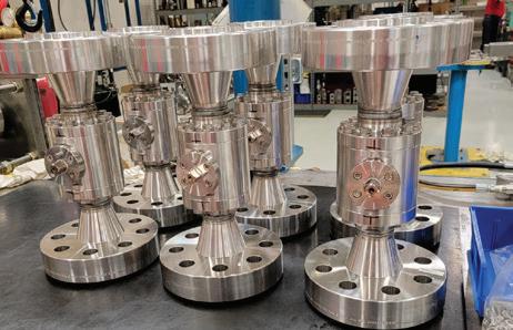
In recreational boating, hydraulic power units (HPUs) provide the muscle behind critical operating machinery used to transport, launch, or secure small craft, including lifts, trailers, and jacks. For boat lifts alone, OEMs produce a variety of configurations, such as bottom standing, piling mount, floating, and shore mounted. These machines and configurations rely on hydraulic systems to function properly. But given the harsh ocean environment, salt spray and other corrosion-causing factors can wreak havoc on hydraulic components.
10 FLUID POWER WORLD 4 • 2023 www.fluidpowerworld.com
DESIGN NOTES
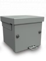
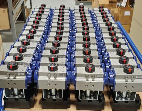
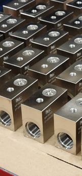
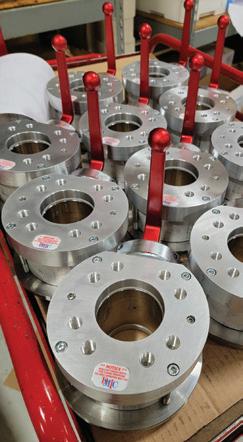
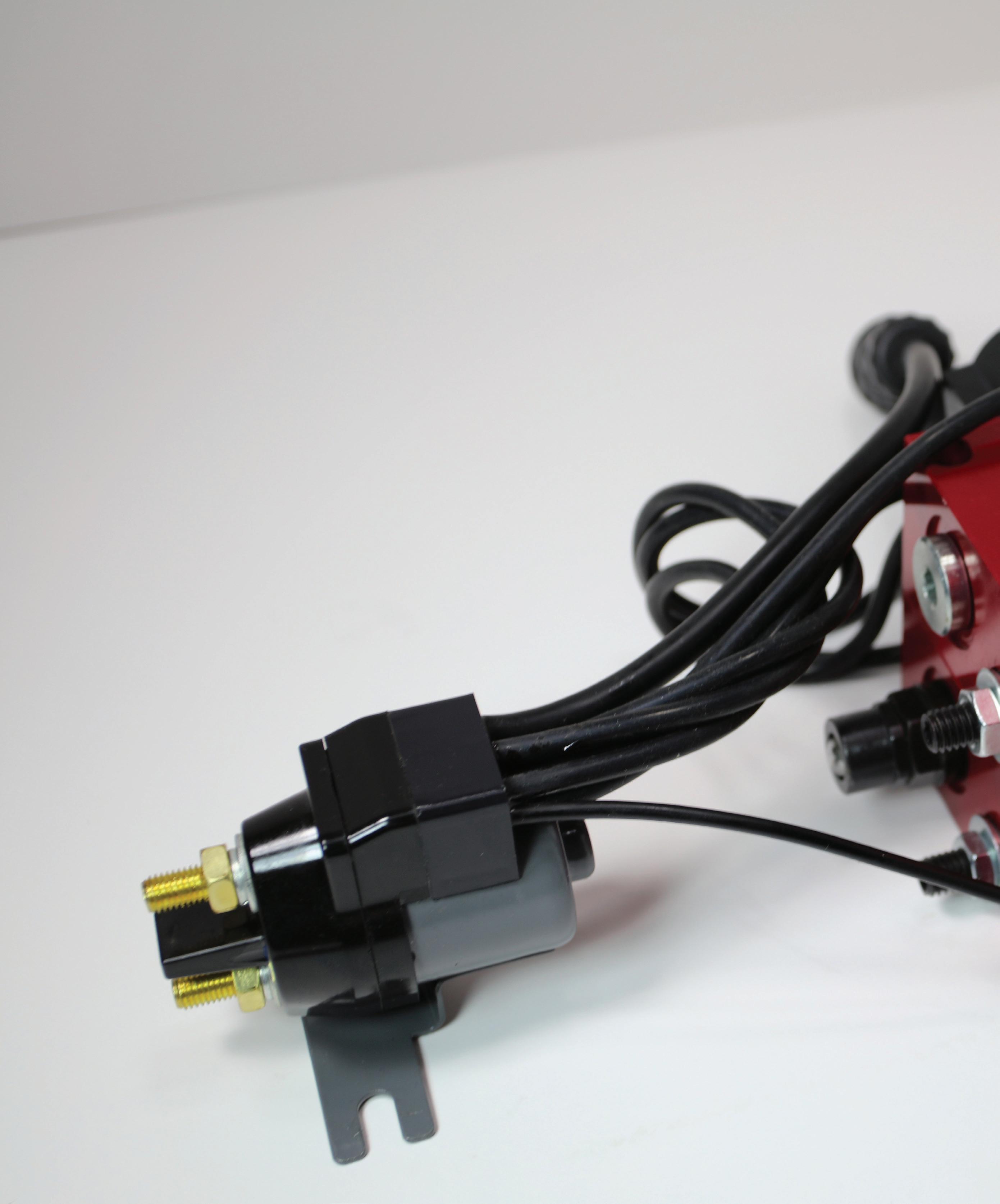
To save inventory space and costs, distributors can purchase a single SKU item and then the needed manifolds, such as this double-single manifold.
For decades, there has been little variation in the basic component configuration of HPUs, which convert electrical power to hydraulic energy. Highly complex hydraulic systems consist of many components, including manifolds, directional valves, heat exchangers, pressure gauges, and the motor and pump, which are mounted to the top of the oil reservoir. Additional components such as filters, pressure gauges, and heat exchangers may also be needed to meet application requirements.
While the design is technically sufficient, OEMs have long sought ways to improve hydraulic systems’ overall reliability in harsh ocean environments. One challenge is that high-value components, such as the motor and pump, are most likely to require repair or replacement in many cases. Yet current HPU design involves mounting the motor and pump to the reservoir, which exposes them to the environment and potential corrosion damage.
Even if the HPU is in a toolbox with the vehicle battery, it is regularly exposed to moisture from weather, washdowns, or the ocean environment. Accelerated corrosion only leads to premature service, repair, and replacement.
Since critical equipment and machinery cannot function without a sound hydraulic system, downtime and lost revenue can also result. When this occurs, OEMs receive service calls and complaints from customers who have problems with the unit. This can reflect poorly on the brand, lead to negative online reviews, and result in future sales losses.
In addition, while not a concern in all applications, compact HPUs are generally preferred where space is limited.
To significantly increase HPU reliability and provide greater design flexibility, KTI Hydraulics redesigned these vital components to create the industry’s first “Submerged DC
www.fluidpowerworld.com 4 • 2023 FLUID POWER WORLD 11
| Courtesy of KTI Hydraulics.
DESIGN NOTES
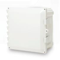
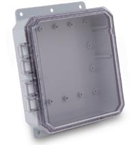
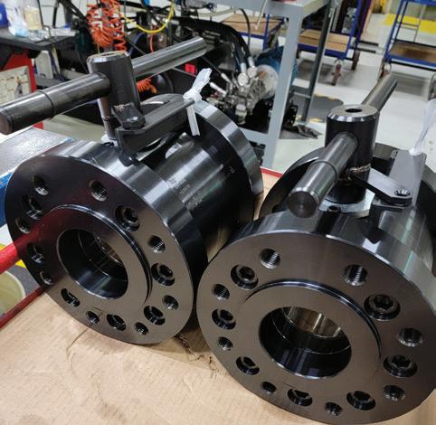
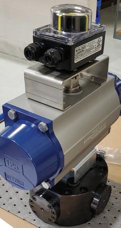
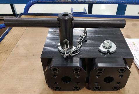
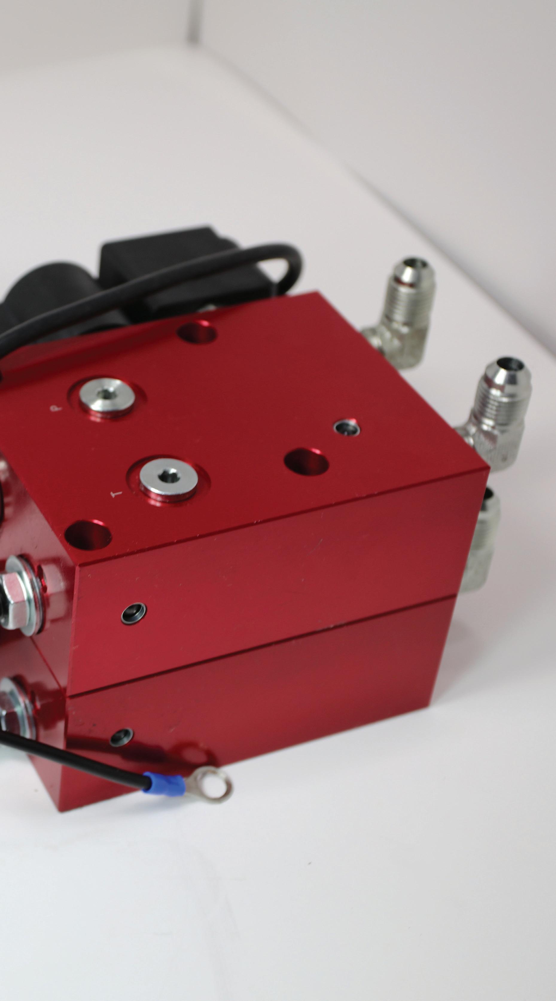
The configurable approach gives OEMs multiple circuit options for one base unit.
HPU.” Founded in 1998, the Santa Ana, California-based company provides HPUs and components for commercial and industrial hydraulic equipment.
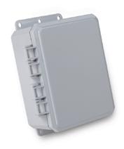
In the patented design, the motor and gear pump are protectively submerged in the reservoir fluid, rather than the typical configuration of mounting the motor, gear pump, and manifold to the top of the reservoir.
Protecting the motor and gear pump in this manner has many benefits. When the motor and gear pump are submerged, the high-value parts require substantially less maintenance and replacement. The new units are ideal for equipment and machinery operating in harsh, corrosive environments. The oil also functions as a coolant, resulting in a longer duty cycle.
The Submerged HPU has a 1.8 kW 12 V and 24 V dc motor with superior ingress protection (IP) ratings a measure of an enclosure’s resistance to dust or liquid intrusion. It includes a pressure-loaded gear pump, a potted solenoid, and a reservoir with five quarts of usable volume. Several optional add-ons are also available.
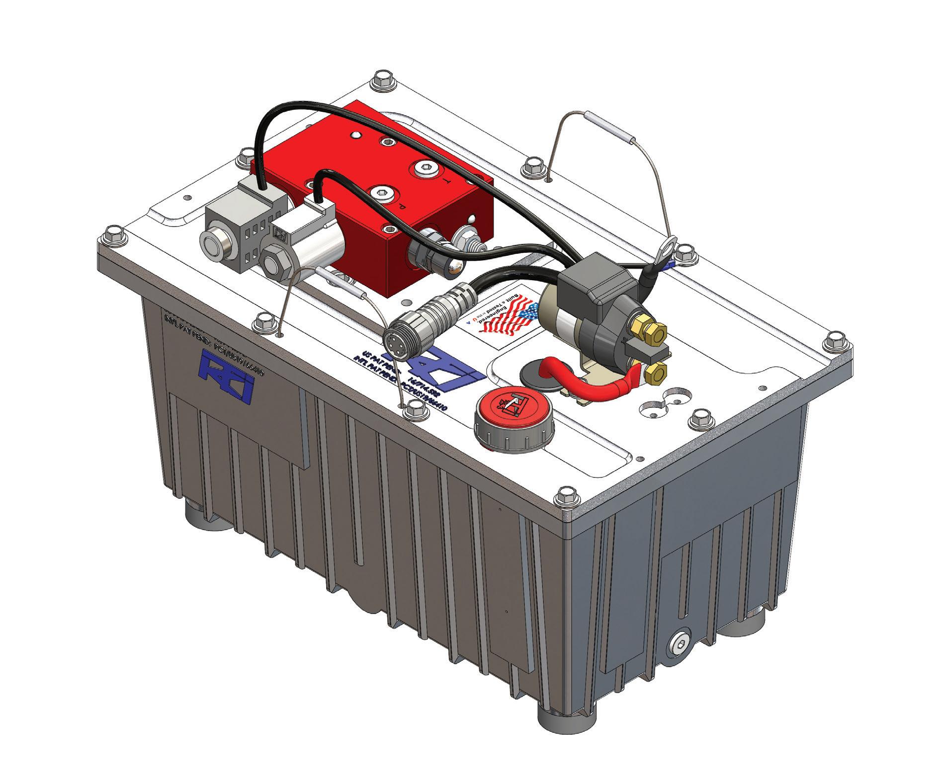
The new configuration enables a more compact design (15 ½ x 9 ½ x 8 in.), ideal for OEMs looking to minimize the space required for hydraulic components.
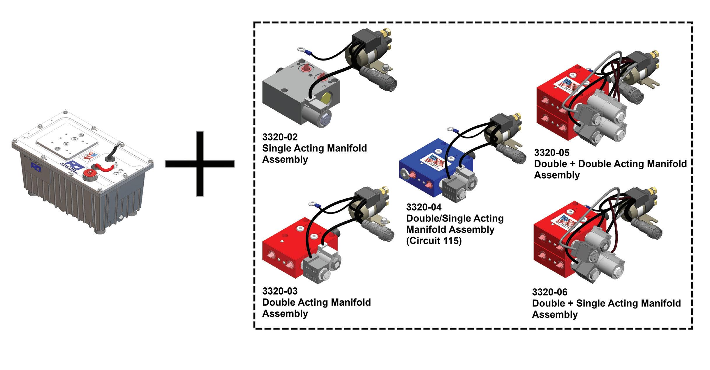
Various standard hydraulic circuits are available, and KTI Hydraulics can design custom circuits upon request. OEMs can change the manifold to work with many different standard or custom circuits. This configurable approach allows one
base unit to use multiple circuits so that OEMs aren’t locked into a single-acting or double-acting configuration.
Additionally, hydraulic equipment distributors conserve inventory space and capital by purchasing a single SKU item
to hold in inventory and then the needed manifolds. This eliminates the need to stock four different types of HPUs.
KTI
12 FLUID POWER WORLD 4 • 2023 www.fluidpowerworld.com
| Courtesy of KTI Hydraulics.
Shown here is an example of the base unit with a double-single acting manifold assembly.
| Courtesy of KTI Hydraulics.
FPW
Hydraulics ktihydraulicsinc.com
QUALITY PERFORMANCE SAFETY
FZH

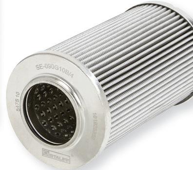
In-line stainless steel pressure filter with threaded connection.
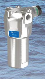
Working pressure up to 700 bar, flow rates up to 80 l/ min.
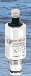
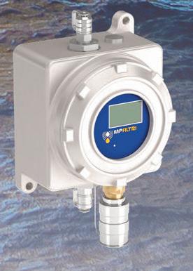
DEH
Designed to work in hazardous or explosive environments, it alerts operators that filter elements need to be replaced, thus ensuring proper continuity of operation.


Working pressure up to 420 bar.
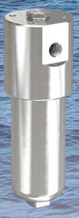
AZ2
Contamination monitoring device suitable for hazardous or explosive environments. It can measure and automatically save the level of particle contamination, humidity and temperature of various hydraulic fluids. Working pressure up to 400 bar.
PASSION TO PERFORM
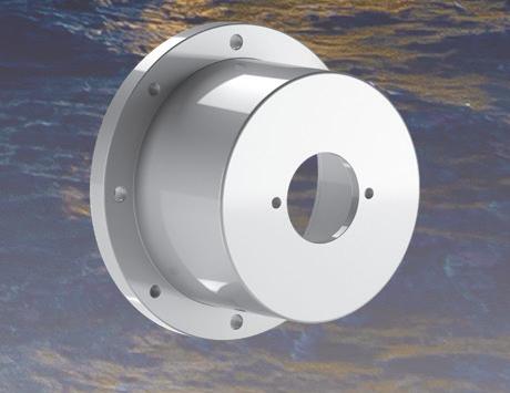
LMC
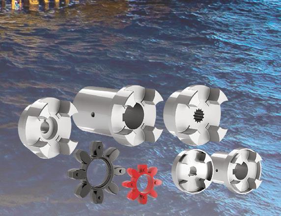
The bell housings LMC/ LDC series are used as connection between IEC electrical motors from size 80 to 355 and pumps with ISO3019 or SAE flange. With anodising treatment they are suitable for use in the off-shore market.
SGEA/G/S


The flexible couplings are used for the connection of electric motors and hydraulic pumps. Available in aluminium, steel and cast iron, they can be machined according to ISO, SAE and DIN standards.
mpfiltri.com
PRODUCTS CERTIFIED ATEX 2014/34/UE www.mpfiltriusa.com (215) 529-1300 sales@mpfiltriusa.com
DESIGN NOTES
 Edited by Rachael Pasini • Senior Editor
aerospace manufacturing Quality air is critical for

Compressed air quality is crucial for aerospace manufacturing, as aircraft components and tools must be of the highest quality and precision. This demanding standard for component quality urges aerospace manufacturers to utilize compressed air with specific requirements. The air must be clean, dry, and unvaried under pressure. If the air becomes dirty, moist, or varies in pressure, it can disrupt operations, hinder product quality, damage equipment assets, and decrease efficiency and uptime
“Compressed air is the heartbeat of our operations, and we cannot afford to compromise our product quality with unreliable compressed air,” said Mark Gabbard, facility manager at Legacy Industries, a Michigan-based manufacturer that produces mechanical parts, robots, and tools for “the big three” aircraft manufacturers.
Air pressure is another crucial factor for aerospace manufacturers. As
14 FLUID POWER WORLD 4 • 2023 www.fluidpowerworld.com
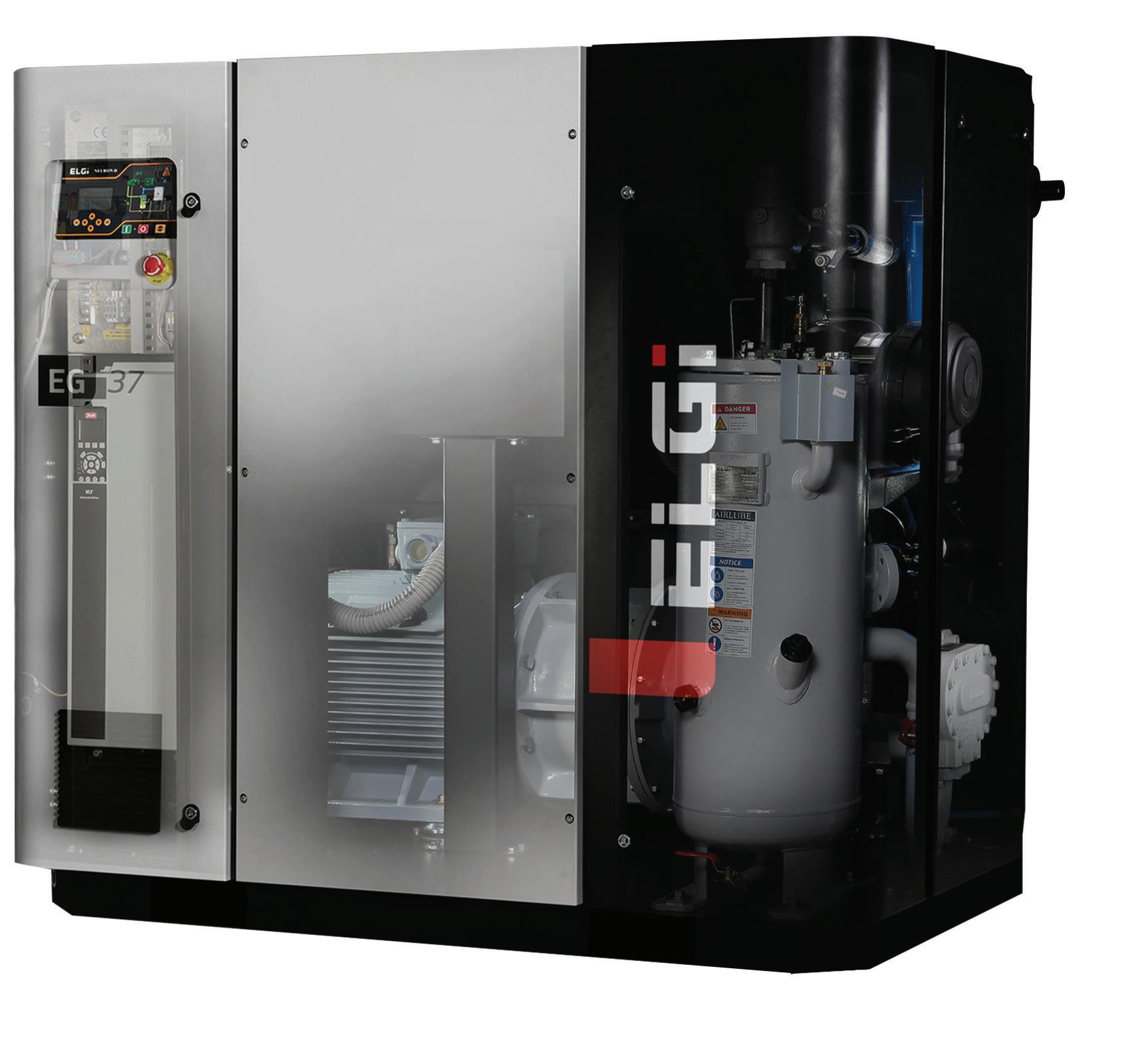
The EG Series includes eta-V profile rotors with a 4/5 lobe combination to reduce pressure losses and increase stage efficiencies. The series ranges from 15 to 300 hp and has an oversized cooling system to prevent overheating.
| Courtesy of Elgi
components and tools for aircraft are highly delicate, constant air pressure can ensure manufacturing precision and significantly decrease the error rate.
“To avoid production losses from factory shutdowns, we used to have two backup air compressors for full redundancy,” said Gabbard. “Our two backup air compressors, one with 30 hp and the other with 50 hp, were experiencing deteriorating performance, and we needed to find replacement options.”
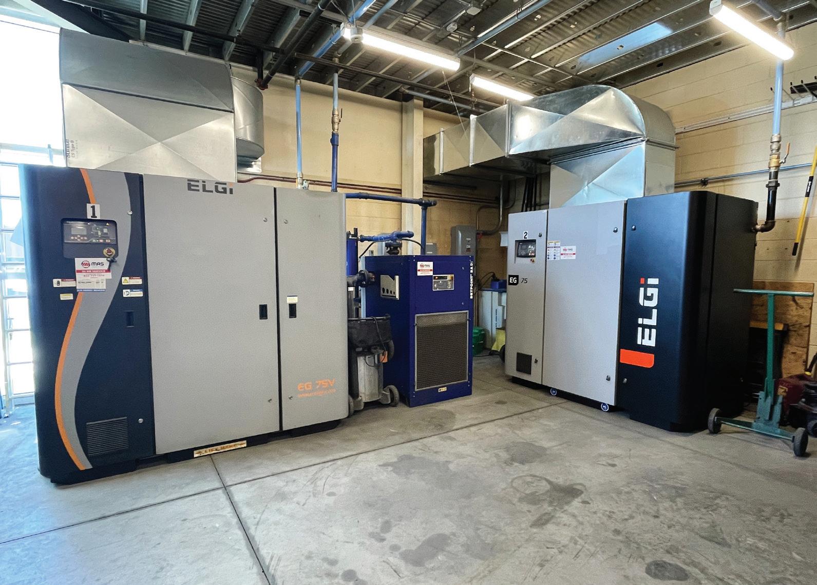
Eight years ago, the company began working with Elgi at its Auburn Hills facility in Michigan. Legacy Industries installed an EG 75V, a 100 hp variable speed rotary screw air compressor reputed for ensuring low oil carryover with its unique OSBIC (Oil Separation by Impact and Centrifugal action) process design. This design enables efficient separation of air and oil in three stages, delivering consistent compressed air quality with minimum pressure drop.
“Since we were happy with its performance, we decided to install another
100-hp EG 75V as our backup air compressor,” Gabbard said. “We’ve never encountered any oil contamination or moisture issues. The quality air enables us to produce the most precise aircraft parts and tools.”
The aerospace manufacturer proactively installed a new EG 75V air compressor to ensure complete redundancy and avoid production downtime. The EG Series comes equipped with eta-V profile rotors with a
4/5 lobe combination. This air end design reduces pressure losses and increases stage efficiencies, leading to an optimized compressed air system. Also, the compressor is designed with an oversized cooling system that prevents overheating and enables continuous peak performance. FPW
Elgi | elgi.com/us
Legacy Industries, a Michigan-based aerospace manufacturer, uses two 100-hp Elgi EG 75V variable speed rotary screw air compressors for redundancy and to avoid production downtime.
| Courtesy of Elgi
Edited by Rachael Pasini • Senior Editor
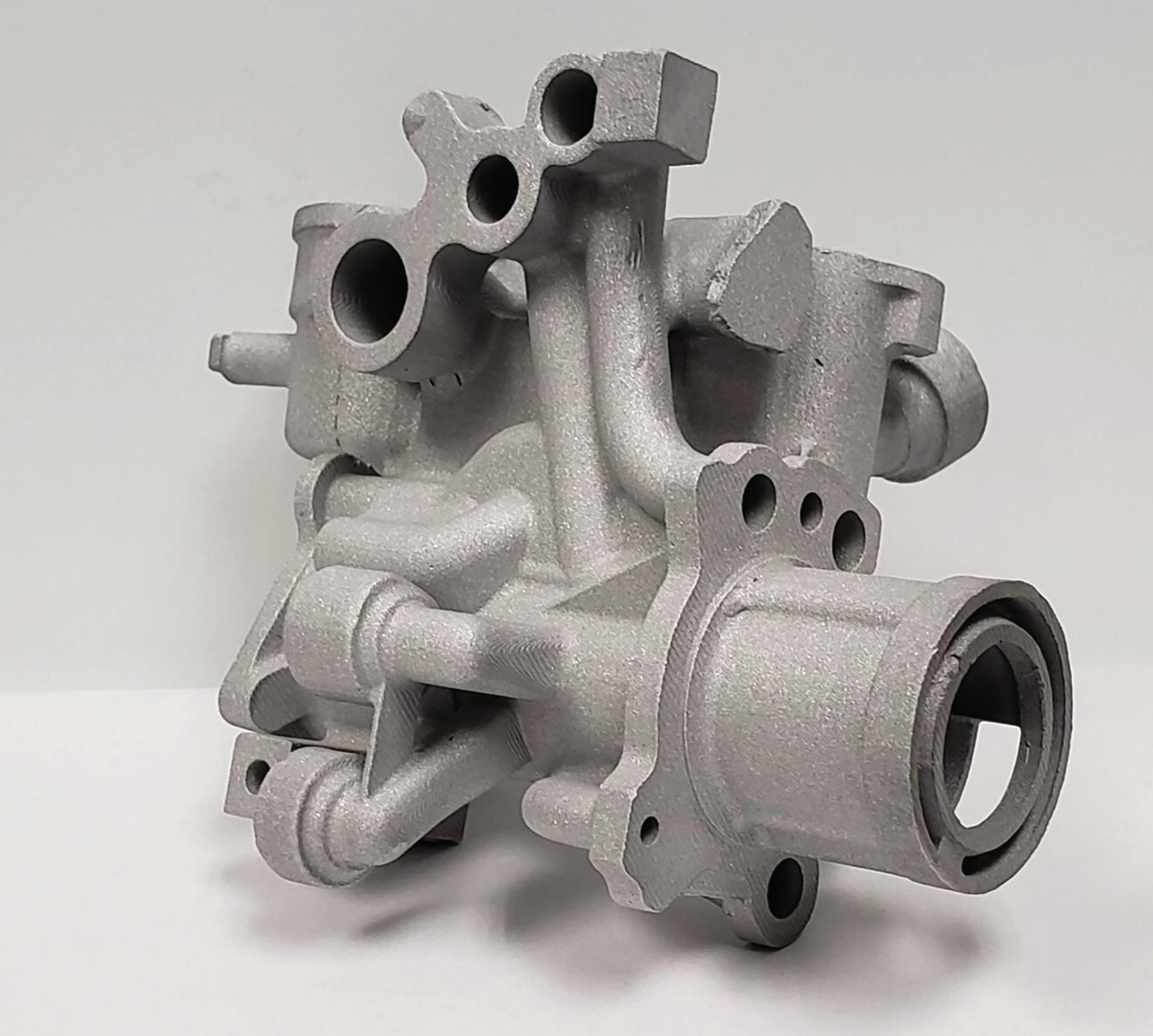
complex parts possible 3D printing makes
For decades, components such as impellers, vanes, pumps, and housings have been manufactured using a labor-intensive, lost-wax investment casting process that requires 12 separate steps. This challenging, costly, and time-consuming process requires additional steps and tooling to create soluble or ceramic cores that form complex internal ports, passages, channels, and baffles.
However, manufacturers now use innovative 3D printing technology to produce monolithic ceramic shell molds with integrated internal cores that arrive at the foundry “ready for pouring.” These molds are designed to cast single, large parts, such as impellers, or can be used to create multiple smaller parts with a few minor additional steps.
Compared to traditional investment casting, 3D printing technology can lower the cost of manufacturing components by more than 50% and decrease lead times for new or modified parts by a factor of ten. The more complex the part, the greater the cost and lead time reduction.
“The advantage of receiving the external shell along with the core in an integrated, monolithic, ready-to-pour mold is significant. With the new 3D printing technology, we can create some very complex internal part geometries that we probably could not create with the traditional process. Some geometries are too complex to make with a traditional die or any other method,” said Marc Riquelme, president of Signicast and OptiMIM.
Signicast is a provider of commercial investment castings based in Hartford, Wisconsin. With facilities across North America and Europe, Signicast serves sectors such as fluid technologies, defense, aerospace, medical, firearms, power tools, mining, and oilfield. OptiMIM is a metal injection molding manufacturer of complex precision components.
The core problem with complex internal geometries
The challenge for investment casting is not creating the external shell but making internal cores, which are critical for functionality and can be very complex. In traditional investment casting, parts that require complex internal cavity configurations are typically created with soluble wax or ceramic cores.
Most applications use a soluble wax core. To create the core, soluble wax is
16 FLUID POWER WORLD 4 • 2023 www.fluidpowerworld.com
DESIGN NOTES
Monolithic 3D-printed shells with multiple integrated cores can be used to produce a complex oil pump casting without tooling, soluble wax cores, or wax patterns.
| Courtesy of DDM Systems
injected into a metal mold to form the geometry of the internal passageways. The core is then ejected from the mold and cooled. The soluble core is placed precisely within the metal mold cavity for the entire component. The position of the soluble core within this mold is held by support points incorporated into the mold during the design process. The mold is then closed, and the pattern wax is injected into the cavity around the soluble core. Once the pattern wax is cooled, the part is ejected from the mold and inserted into a bath of mild muriatic acid to dissolve the soluble core.
When the passageways are particularly complex, pre-formed ceramic cores may be used instead. Like soluble cores, the ceramic cores must be positioned carefully inside the mold for the outer shell. However, they are not removed until after the metal has been cast.
Although soluble wax cores can be effective, they increase process costs and produce significant scrap. Immersion in muriatic acid also increases lead time and costs. Even when ceramic cores are used, a high yield is not guaranteed because cores are notorious for slipping or shifting out of position when the wax melts away.
Ready-to-pour ceramic molds
Although Signicast still uses cores for typical castings, the company now receives readyto-pour ceramic shell molds for complex applications from Atlanta-based DDM Systems. Signicast then pours the shells using traditional investment casting methods.
DDM’s Digital Foundry technology can produce precision investment castings of complex engineered components without upfront investment in hard tooling, without patterns, and by using 3D-printed ceramic shell molds with integrated internal cores.
The first step is taking a CAD model of the casting to design and 3D print ceramic shell molds with integrated cores using a process called LAMP (Large Area Maskless Photopolymerization). The technology involves a ceramic resin cured with UV light to produce the shell molds layer by layer. In LAMP, the 3D “printer head” projects images in UV light onto the resin, causing it to solidify in patterns corresponding to slices of the shell.
The resulting ceramic structures can achieve the high level of detail expected of investment casting grade cores and molds. Once the ceramic
shells are printed, they must undergo a thermal processing step using well-established techniques for firing ceramics. DDM possesses trade secrets related to ceramic formulation and firing.
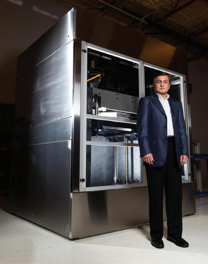
According to Suman Das, founder and CEO of DDM Systems, LAMP significantly reduces costs by eliminating the first seven of 12 steps typically required to produce a traditional investment casting shell. These seven steps account for 90% of all scrap and approximately one-third or more of the total manufacturing cost of producing an investment casting, depending on the part’s complexity. This does not consider eliminating the extra process steps and tooling requirements to create soluble or ceramic cores, which only add to the staggering costs and long lead times.
With their approach, DDM can engineer, print, fire, and deliver monolithic shells with integrated cores in as little as 10 days. The printed ceramic shell is compatible with all airmelt foundry processes to produce fluid-handling parts in steel, aluminum, and nickel alloys.
“Because the Digital Foundry process can produce printed and fired shells with integrated cores that are ready to pour in two steps without any tooling, the overall lead time for castings can be one-fifth or less of the time taken by conventional methods,” said Das.
The integrated, monolithic ceramic shells can be used to cast a single, large item, such as a 10-in. diameter impeller, or multiple smaller parts using a slightly revised, hybrid investment casting approach. For multiple parts, the ready-to-pour printed and fired shells are attached to a wax sprue and coated in a slurry to provide an additional layer of ceramic that coats the wax sprue and shells. When it dries, it creates a continuous ceramic body ideal for investment casting.
This approach can also cost-effectively streamline the investment casting of rapid prototypes when traditional methods are not ideal. By eliminating much of the cost and lead time, manufacturers can cast a range of design variants to conduct qualification and “rainbow wheel” tests to optimize the design of various parts. FPW Signicast
www.fluidpowerworld.com 4 • 2023 FLUID POWER WORLD 17
signicast.com
| optimim.com
Systems | ddmsys.com
|
OptiMIM
DDM
Suman Das, founder and CEO of DDM Systems, stands next to the LAMP 3D printer that eliminates seven steps of the investment casting process, saving cost and lead time.
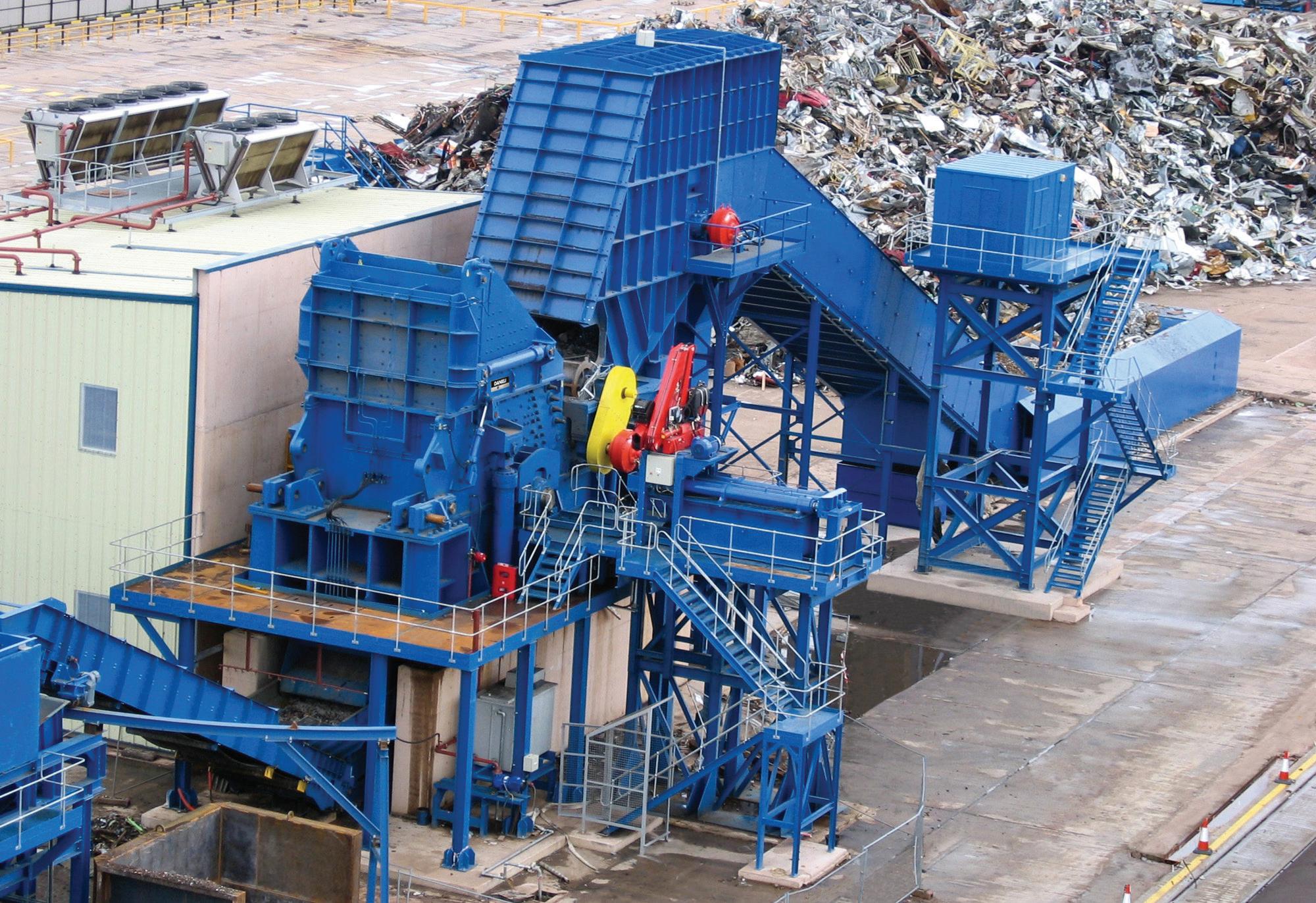
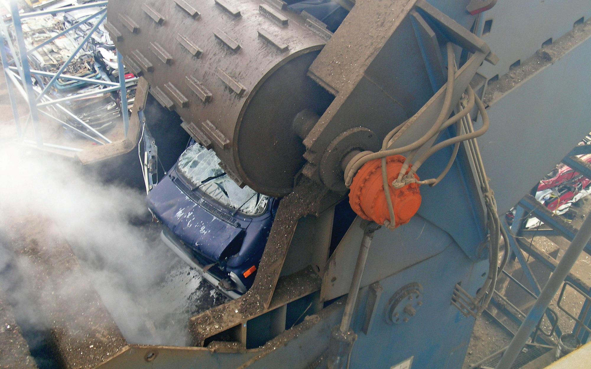
hydraulic drive service matters 5 reasons why
Hydraulic direct drive systems are a crucial part of industrial recycling operations. Engineered for reliable performance under demanding conditions, recyclers and other users of these systems will sometimes postpone critical maintenance practices because the drives are so rugged and reliable.
The risk: Even the best hydraulic systems can have problems that can lead to reduced energy efficiency, increased safety incidents and, ultimately, “breakdown maintenance” with costly unscheduled downtime. Avoid the risks of breakdown maintenance and reap the rewards by incorporating these drive maintenance best practices into your operations.
1. Periodic maintenance checks
Risk: Expensive and disruptive downtime
Emergency repairs are often more difficult and costly to make. When small problems or malfunctions persist, they can become major failures requiring drive removal and shipping to repair centers, potentially taking a vital shredder or other major piece of equipment offline.
Reward: Increased uptime and cost control
Best practice is to implement monthly hydraulic equipment inspections — and make sure they aren’t skipped. These can prevent minor issues from becoming major problems. Document danger signs, such as main pump pressure changes or fluctuations in motor speeds, and then schedule further service work if the issues persist.
2. Fluid selection and condition
Risk: Poor equipment performance
Substituting the wrong hydraulic fluid instead of the fluid specified by the drive manufacturer can lead to less efficient drive performance. Equipment like infeed conveyors, double feed rolls, scrap shears, and baling presses are exposed to contaminants like high dust levels or metal shards that can contaminate fluids and ultimately damage hydraulic motor components.
Reward: Protection from equipment damage
Follow the manufacturer’s recommended fluid viscosity ratings and consider environmental factors, such as high-temperature conditions. Regularly monitor hydraulic
MAINTENANCE 18 FLUID POWER WORLD 4 • 2023 www.fluidpowerworld.com
Timothy McCrea • Market Segment Manager, Aftermarket, Pulp & Paper • Hägglunds - Bosch Rexroth
Complex recycling operations rely on the reliability of hydraulic direct drives.
fluid for contaminants, particles or discoloration; degrading oil condition is a critical warning sign that motor components can be worn or damaged.
3. Service filters and seals
Risk: Contaminant damage
Based on an environment’s dust and contaminants, drive manufacturers provide filter specifications and replacement intervals. Using alternative filters or skipping filter replacement, especially on equipment like shredders or conveyors that undergo high levels of shock loading, risks fluid contamination and damage to drive components.
Reward: Smoothly operating drives
Following all the manufacturer’s recommendations on filter selection and replacement is the best way to maintain the long-term health and performance of drive hydraulic fluid. In addition, check O-ring seals for signs of leakage that may indicate seals are wearing out due to shock loading and vibration, and schedule O-ring replacement and tightening of fittings.
4. Use OEM-sourced parts
Risk: Breakdowns due to “remanufactured” parts
Some repair shops will repair hydraulic direct drives with used parts taken from scrapped motors or from third-party aftermarket suppliers. Use of these parts cannot provide the same guaranteed level of reliable performance under high shock load conditions that are provided by the manufacturer’s supplied replacement parts.
Reward: Confidence in “like-new” performance
When repairing hydraulic direct drives, using original parts manufactured to the manufacturers specifications is the surest way to return the drive
to proper “like-new” operating conditions. This includes making sure that any internal wearing parts with proprietary coatings function according to original specifications.
5. Choose OEM-certified service providers
Risk: Incorrect repair or maintenance work
Direct drives are complex, highly engineered systems. Third-party service shops that perform general industrial hydraulics repairs will typically not have the detailed equipment specifications or trained personnel to properly repair, calibrate and test the motor to like-new condition.
Reward: Job done right every time
Service facilities provide OEM-certified technicians fully trained in servicing direct drive systems, following detailed repair processes and specifications. Plus, by using service facilities, you automatically have original parts used in repair or maintenance work.
Best practice: comprehensive preventative maintenance programs
Work with your manufacture’s specialists to follow these best practices and implement a comprehensive preventative maintenance program. Specialists can visit your sites and perform detailed inspections of all accessible equipment and assess data points, such as motor temperatures, pump settings, speed and motor performance, and other factors. They then provide detailed reports and recommendations on maintenance steps, parts replacements, and other follow-up actions. FPW
Impact of “breakdown maintenance”
A major recycler had four Hägglunds hydraulic drive systems installed on critical equipment – and unfortunately, general maintenance practices were overlooked for years. When an unplanned drive shutdown occurred, Hägglunds service personnel went onsite and discovered issues on not just one, but all four machines:
• Hydraulic fluid was severely contaminated
• Pumps were completely worn out
• The Hägglunds motors significantly exceeded their service life

A major case of breakdown maintenance. The pumps and motor on the down machine were emergency shipped to the Hägglunds repair center for quick turnaround rebuild. The Hägglunds systems on the other three machines were sequentially taken out of service and sent out for repairs as soon as one set of equipment was returned, so at least some of the equipment could be kept in operation.
What preventative maintenance … prevents
The emergency freight, the quick turnaround repairs, and the downtime the recycler experienced incurred a tremendous cost — and could have been prevented. The recycler now has a Hägglunds Preventative Maintenance program that consists of two onsite visits per year. The annual cost of this program? About the same amount the recycler spent on emergency freight for just one Hägglunds drive. The payback? Peace of mind that going forward their Hägglunds systems will be expertly maintained — not just when breakdowns occur.
Bosch
www.fluidpowerworld.com 4 • 2023 FLUID POWER WORLD 19
hagglundsservice-recycling
Rexroth Corp. boschrexroth-us.com/
Hydraulic direct drives are rugged and reliable in the toughest environments but consistent, proactive maintenance ensures uptime.
By Josh Cosford • Contributing Editor
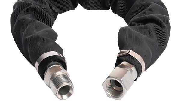
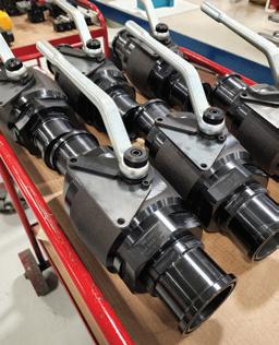
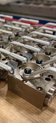
When should you use
permanent hose fittings
Hose fittings (also called hose ends) are crimped or threaded onto either end of a hydraulic hose assembly and provide the technician with an interface to connect the system’s conduits. Hose end fittings come in two primary styles; field-serviceable screw-on and permanent crimped-on. This article discusses when you should use permanent hose fittings in your application.
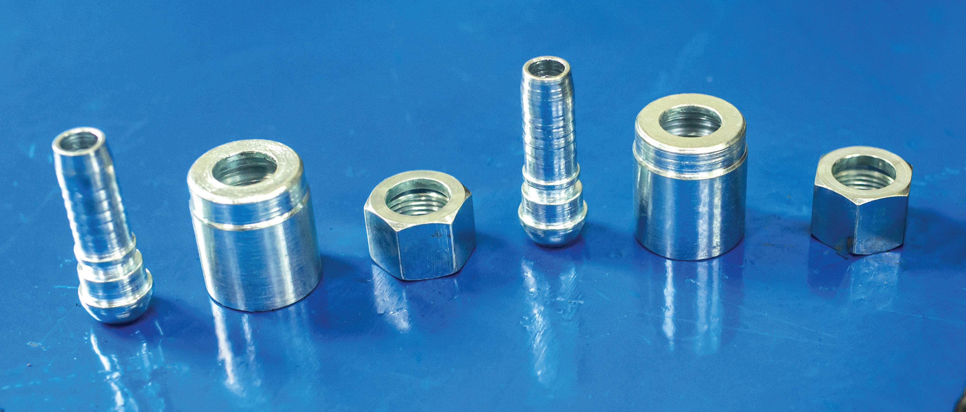
We can agree that leaks are not the desired outcome when considering the plumbing of your hydraulic system, so any choice that prevents such leaks is an easy one. The crimp-on hose fitting has an annular clearance in which the hose inserts before the crimping procedure. The stem of the fitting resides within the hose ID while the ferrule surrounds the hose OD, and its size depends upon the hose construction itself (such as the requirement for 1-wire or 2-wire reinforcement).
Permanent hose fittings come available in either single or two-piece designs, but what matters is that when this hose end is crimped onto the hose, the deformation of the ferrule clamps permanently onto the hose. If you wish to remove the hose end, it must be cut off (using the appropriate blade to prevent fraying, of course). The teeth inside the ferrule shear through the rubber outer cover and into the reinforcement layer, thereby preventing the separation of the hose and fitting even under pressure.
You should use permanent hose fittings for any machine with infinitely fixed fluid connections, especially those with expected long service life. Unless your hose requires occasional but regular
replacement of hose ends, such as those applications which cannot avoid excessive movement at the joint, there is no reason to change or replace the hose end. The exceptions are rare, such as highpressure tooling (think jaws of life), where actuators might cause the hose to bend at the point of fitting connection or where physical force occasionally tears the hose out from inside the fitting.
When you expect your hose to last indefinitely, crimped fittings will provide the most reliable solution this side of tubes. Tubes are more resistant to many external nefarious influences but obviously do not offer the literal flexibility of a hose, and neither can they dampen sound or vibrations when applied strategically.
Hydraulic hoses and fittings offer a 4:1 safety ratio, meaning their burst pressure rating is at least four times their rated working pressure. The completed hose assembly must achieve the same safety ratio, and a precisely crimped hose fitting is hugely advantaged over a fieldserviceable one. Permanent fittings achieve a precise clamp, and the result must fall within thousandths of an inch or the assembly should be remade correctly. Each hose construction type —ranging from spiralwound reinforcement to six-wire spiral hose — requires a specific crimp dimension (and often specific hose end fitting).
Reusable fittings cannot clamp directly to the hose’s reinforcement and instead screw onto the hose and reinforcement. If the teeth of the screw are not ideally matched, the hose end may come off when pressurized. Conversely, a tight fit may cut into the reinforcement, reducing the joint’s integrity and resulting in failure under pressure. A permanently crimped hose fitting provides the most reliable hose assembly for most hose applications. FPW
FUNDAMENTALS
20 FLUID POWER WORLD 4 • 2023 www.fluidpowerworld.com
| Courtesy of Adobe Stock


 John Joyce • Global Marketing Director, Brennan Industries
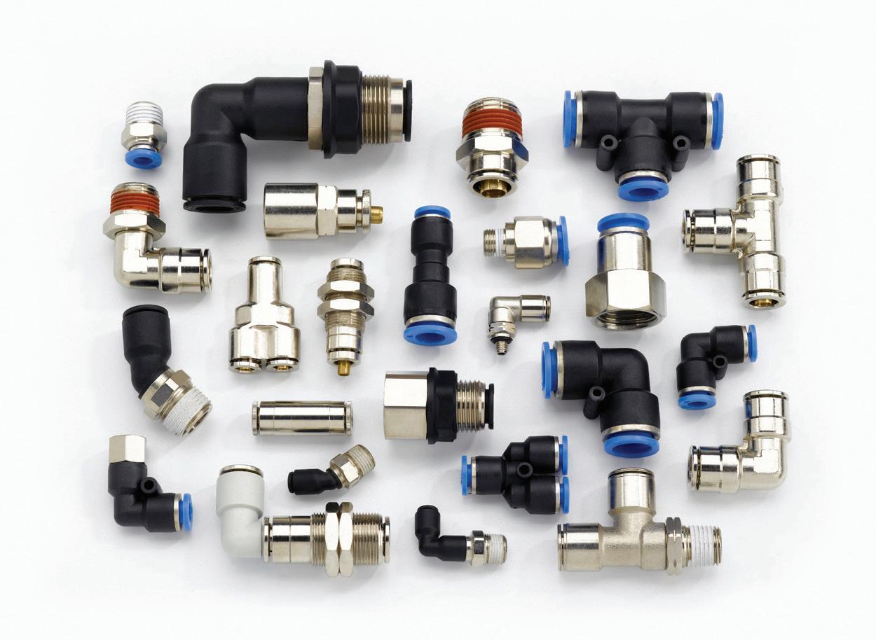
The case for push-to-connect
pneumatic fi ttings in industrial automation
IIndustrial automation requires a high level of performance while enhancing safety, saving time, boosting quality, and lowering costs. Pneumatics is used heavily in automation to provide gripping, clamping, pick-and-place, and more. As a result, reliable, efficient, and leak-free systems are imperative.
Pneumatic fittings must allow for the necessary flow without creating significant drops in pressure. Working pressure, temperature, environment, and maintenance should all be considered when choosing a quality pneumatic fitting for your system.
In fact, selecting the correct pneumatic fitting is especially crucial for applications utilizing industrial automation because of the need for precision and high output. It is important that machinery is working
efficiently to allow for repetitive and precise tasks to be completed quickly. By having the correct fittings, you can not only meet the needs of an industrial automation application but also decrease energy consumption, save time on assembly, and eliminate leaks.
Pneumatic fittings come in different materials, depending on the style. Push-toconnect fittings are a popular method for connecting flexible pneumatic tubing with industrial robots and other machinery. They provide quick and simple connections. Push-to-connect fittings allow for easy connections without having to glue, solder, or use clamps or compression-style unions. They are proven to provide highly reliable connections, even behind panels or other enclosed areas. Push-to-connect fittings help save on installation time and ensure reliable operation.
Downtime can paralyze the entire system. When machinery is down,
productivity and profit are lost. And while downtime costs can vary depending on the size and nature of a facility, it can be prevented by installing the correct parts. Two other common fitting types exist other than push-to-connect — barbed and compression fittings. But, because push-toconnect are much easier to use, they can provide many benefits to most applications.
Those benefits include the following:
1. Decreasing energy consumption — A great deal of energy loss is due to the leakage of compressed air. It is crucial to ensure there are no weak links where leakage can occur. And with push-to-connect fittings being so fast to install, they will pay dividends throughout the system’s life-cycle, as they require regular checks and maintenance.
2. Saving time on assembly — Whether a new installation or an emergency repair, saving time is saving money. The ability to make a fast and reliable connection is crucial for industrial automation, which is why push-toconnect fittings are ideal. They are easily detached or inserted in new tubing or when performing other maintenance.
3. Eliminating leaks — With push-toconnect fittings, a leak-free seal is achieved by quickly pushing the fitting into the tube or hose. Compression fittings often need to be retightened to stop leaks, which can cause distortion of the fitting threads or force the ferrule to cut into the tube, increasing the chance of leaks. Push-to-connect fittings, on the other hand, rarely require adjusting after installation. FPW
Brennan Industries brennaninc.com


22 FLUID POWER WORLD 4 • 2023 www.fluidpowerworld.com
COMPONENT FOCUS


YOUR PARTNER FOR A BETTER TOMORROW High Performance Vane Pumps for Material Handling Satisfaction Guaranteed • ISO 14000 • The most versatile pumps in the industry! Our products are made for mobile and industrial applications 3410 Delta Drive • Portage, IN 46368 • Tel: (219) 762-2059 • Fax: (219) 762-2066 • www.alaindustrieslimited.com ALA Industries Limited
Edited by Mary C. Gannon • Editor-in-Chief
IFPS continues to add new content, training options at Spring Meeting
At the IFPS Spring Meeting, held in New Orleans, February 27-March 2, more than 90% of attendees were in person.
It was noted that the Education Committee has continued to develop new training videos to help with certification preparation. Since the IFPS’ Fall meeting in San Diego, the society has developed two new educational videos visible to members only: Proper Identification of Fasteners and Fittings and a Fluid Power Symbology video. The committee will continue to develop these of types of videos. The Education Committee has also continued to diligently work on releasing brand-new IFPS safety posters. The feedback on the newly released Fluid Power Math & Hydraulic Mechanic Training Modules is excellent, and they are selling well, said Donna Pollander, IFPS CEO.
The IFPS has also successfully conducted two Fluid Power Fundamentals Courses in conjunction with Waukesha County Technical College. “This course is a firm foundation for anyone who wants to learn fluid power basics, and IFPS will continue to offer them for as long as they remain popular,” Pollander said.


In addition, IFPS was presented with an opportunity to partner with the Auburn Career Center in Greater Cleveland to use IFPS certifications as the basis for their curriculum starting with the Connector & Conductor (C&C) certification. The C&C pilot occurred in January and finished in February. “Based on the initial feedback, the pilot was a success! The advisory committee will meet soon to debrief and start planning the second semester,” Pollander said. “The IFPS hopes to launch more programs like this in other locations. IFPS has launched an instructor-led HS Review Training course, a 12-week Certification Review led by Tom
Blansett. The committee has plans to run these types of courses in the future, starting with the Pneumatic Specialist Certification in late summer/early fall.” Certified members interested in participating on any of the subcommittees should email Donna Pollander at Dpollander@ifps.org. The committee plans to upgrade the pneumatic mechanic once the technician certifications are underway.
Other IFPS news includes:
• The Hydraulic Specialist test translation to Spanish is complete and is available to purchase. The committee will begin working on the translation of the MHM written test this month.
• Additionally, a new grant program is available for educators to obtain their first certification – free.
• The mentorship program, which was launched last year, will continue but will limit the mentors and mentees to five, with additional clearer communication.
• A fully upgraded C&C Certification Study Manual and test is set for late spring/early summer 2023.
• Updated materials for the MHM (Mobile Hydraulic Mechanic) certification test and a major revision of the ECS (Electronic Controls Specialist) certification will be released this fall. FPW IFPS ifps.org
WATCH 24 FLUID POWER WORLD 4 • 2023 www.fluidpowerworld.com
ASSOCIATION
IFPS is offering membersonly symbology training videos, as well as a video on fittings and fasteners.
14th IFK 2024 fluid power conference in Dresden issues call for papers
NFPA: Save the date for future events
While the NFPA Vehicle Challenge happened this month and we await results, NFPA encourages members to save the dates for its future events happening over the next few months.
The 14th International Fluid Power Conference (14th IFK) will take place in Dresden, Germany, from March 19 to 21, 2024. As one of the world’s most important conferences in the field of fluid-mechatronic drive and control technology, the IFK has established itself as a central forum for international exchange in the fluid power industry. The IFK is headed by Prof. Jürgen Weber (Chair of Fluidtronics, TU Dresden) and has been held every 2 years since 1998, alternating between Aachen and Dresden.
The motto of the 14th IFK is “Fluid Power: Sustainable Productivity,” with which the conference addresses one of the central challenges of today’s society: sustainable and environmentally friendly technology without loss of performance. In addressing this task, the enormous variety of novel fluid power components as well as drive and system architectures plays a decisive role.
The symposium on the first day of the event will be devoted primarily to research-focused contributions. The two following conference days will provide a comprehensive application- and technology-oriented overview of the state of the art in fluid technology. In this combination, the IFK is a unique forum for exchange between university research and application-oriented industrial experience. An accompanying exhibition offers the opportunity to learn directly about products and to connect with manufacturers, researchers, and users.
High-quality and captivating scientific contributions are the foundation of the conference. Everyone who wish to present their current scientific work to a broad audience are cordially invited to contribute to the 14th IFK. To do so, submit your abstract in English at www.ifk-dresden.de no later than June 18, 2023. There you will find the template for preparing abstracts. Notifications of abstract acceptance will be sent July 23.
The IFK is dedicated to practical topics in stationary and mobile hydraulics and pneumatics. Detailed considerations of hydraulic, pneumatic, actuator, and sensor components as well as fluid technology fundamentals will be presented. Particular importance is given to increasing energy efficiency and the necessary trends such as digitization, virtualization, and data-based applications. Contributions on special applications of fluid technology such as medicine, robotics, and the food industry are also welcome.
14th International Fluid Power Conference ifk-dresden.de
Upcoming events include:
• Quarterly Technology Conference, June 1 — “Fluid Power and the Drive Towards Autonomous Functions and Operations.” This virtual event is held jointly with the Fluid Power Industrial Consortium (FPIC) and features online networking opportunities as well as technical presentations by industry experts. Sessions will include: Integrated Cartridge Valve Sensing Techniques for Improved Closed Loop Control by Bernd Zahe, Sun Hydraulics; and Autonomy and Guidance in Worker Interactions for Fluid Power, presented by Dan Bagley, B&B Management Labs, and more.
• 2023 Industry & Economic Outlook Conference, August 15-16 — Held annually, the IEOC will be located at the Westin Chicago Northwest, and will feature many of the usual favorites, including ITR Economics’ Alan Beaulieau, Jim Meil of ACT Research, Eli Lustgarten of ESL Consultants, and others. The event also features a NFPA Foundation golf outing and various networking opportunities. Registration opens in May.
• The 2024 Annual Conference will be held February 27-29, in Orlando.
Learn
www.fluidpowerworld.com 4 • 2023 FLUID POWER WORLD 25
more at nfpa.com.
Ron Marshall • Contributing Editor
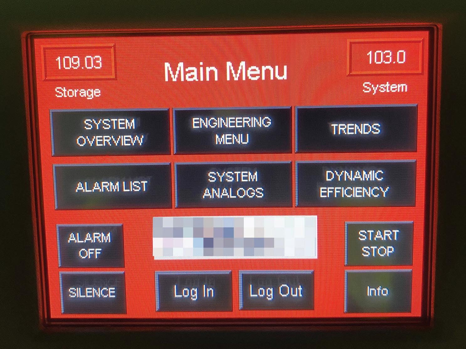
Why is compressor control important?
WWhen controlling screw compressors, the goal is to try to keep all the running compressors fully loaded except one. And the one running partly loaded (called trim) is selected as the one having best part load efficiency characteristics.
When there are only two or three compressors in a group, it is quite easy to set them up manually with cascaded pressure bands. However, as the number of compressors in the group increases, it gets more difficult to meet the stated goal.
On the upper end of the operating pressure band is the maximum rating of the compressors; on the lower end is the lowest allowable system pressure. As we try to cram more and more compressor setpoints in this narrow window, the settings get closer and closer, resulting in some undesirable overlap.
To solve this problem, compressor controllers are used to logically select the next compressor to load or unload within a single compressor band. This allows any number of compressors to run, meeting the goal of optimum control. There are many compressor controllers available on the market, ranging from very simple to very complex and sophisticated.
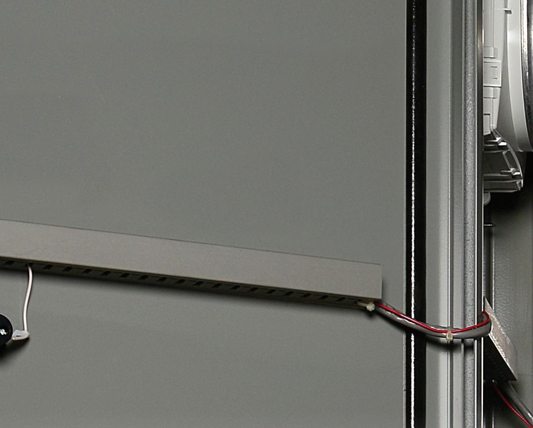
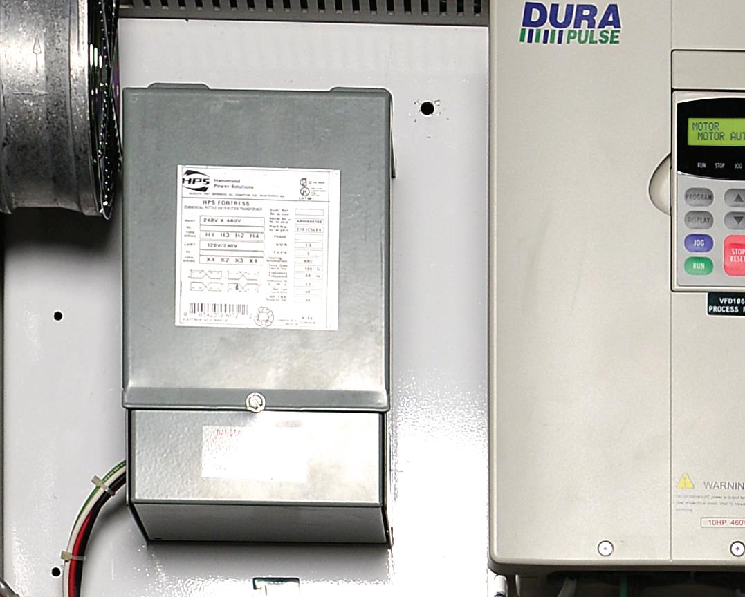
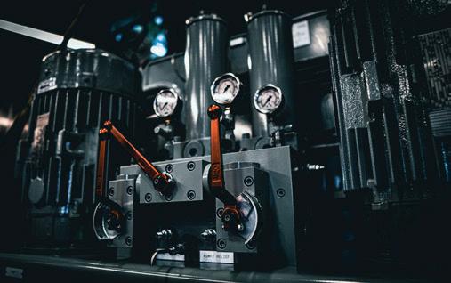
All of these controls suffer from a significant flaw — not in the controller itself, but in the behavior of the operator. Most controllers require the operator of the compressors to understand the workings of the controller. And due to staff turnover and high workloads, there is often little time to read the manual to learn the operation. And this is where the problem began for the controller in the included Figure.
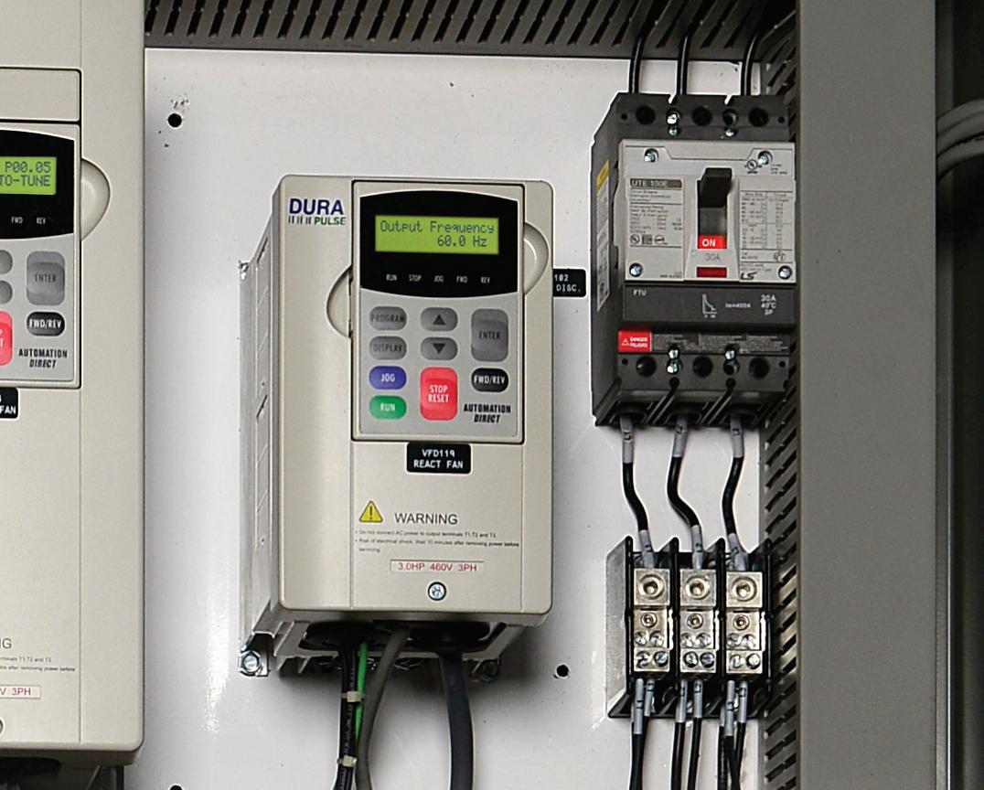
The controller shown is one of the best offered on the market today, yet it is not properly controlling the connected compressors. Why? Because the control has been deliberately disabled. The
compressor operator simply could not understand the control functions — so he turned it off, causing the compressors to run inefficiently. Purchasing an expensive controller is one thing, but “best practices plants” need to ensure there is proper training in place, so operators can learn how to use available tools. FPW
This compressor controller is one of the best and most sophisticated controllers available, but suffers from one flaw — it is not controlling anything due to operator error.
26 FLUID POWER WORLD 4 • 2023 www.fluidpowerworld.com
EFFICIENCY
ENERGY
Making sense of hydraulic manifold mazes
 Josh Cosford, Contributing Editor
28 FLUID POWER WORLD 4 • 2023 www.fluidpowerworld.com MANIFOLDS
Learn how three manifold designs — the common hydraulic integrated circuit, stackable bar designs, and simple passageways for pressure or return — are manufactured for hydraulic designs.
Whendiscussing manifolds, your mind will go to one
of two places — bar manifolds with sandwich valves mounted atop or integrated circuits with a series of cartridge valves constituting a hydraulic circuit. The truest form of manifold contains no valves at all – consider the exhaust manifold on a vehicle, which is just a series of passageways that combine exhaust gas flow into a single outlet.
Such a manifold also serves a purpose in hydraulics and may exist on either the pressure or return sides of a hydraulic circuit. Running the primary line into a manifold provides a tidy method to split downstream functions without the mess of tees and adaptors for a single hydraulic source that supplies many downstream functions. More commonly, the return line manifold joins each separate function’s tank flow into one large chamber, where it may flow into a filter before returning to the reservoir.
www.fluidpowerworld.com 4 • 2023 FLUID POWER WORLD 29
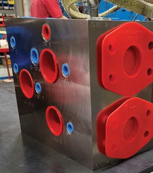
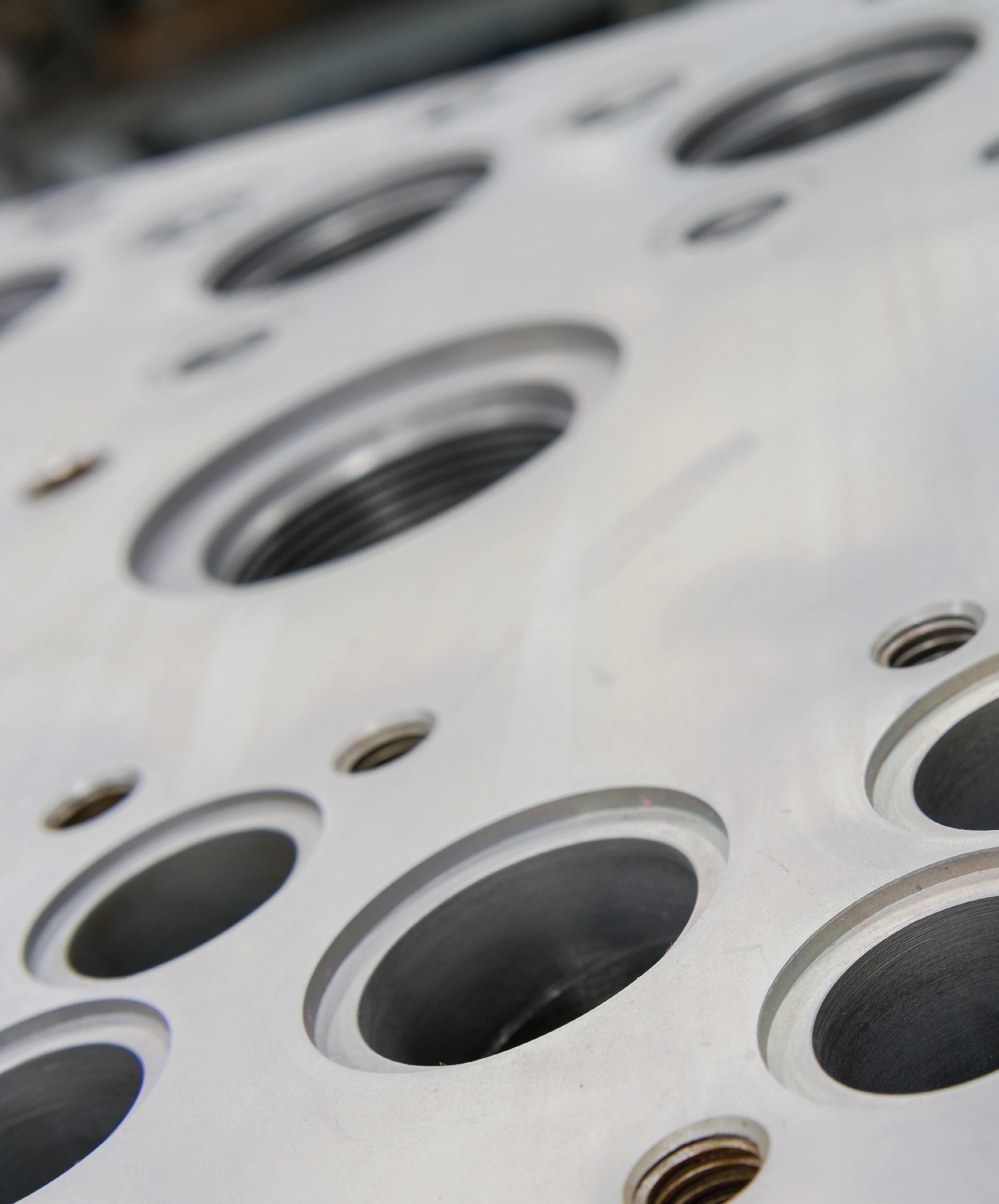
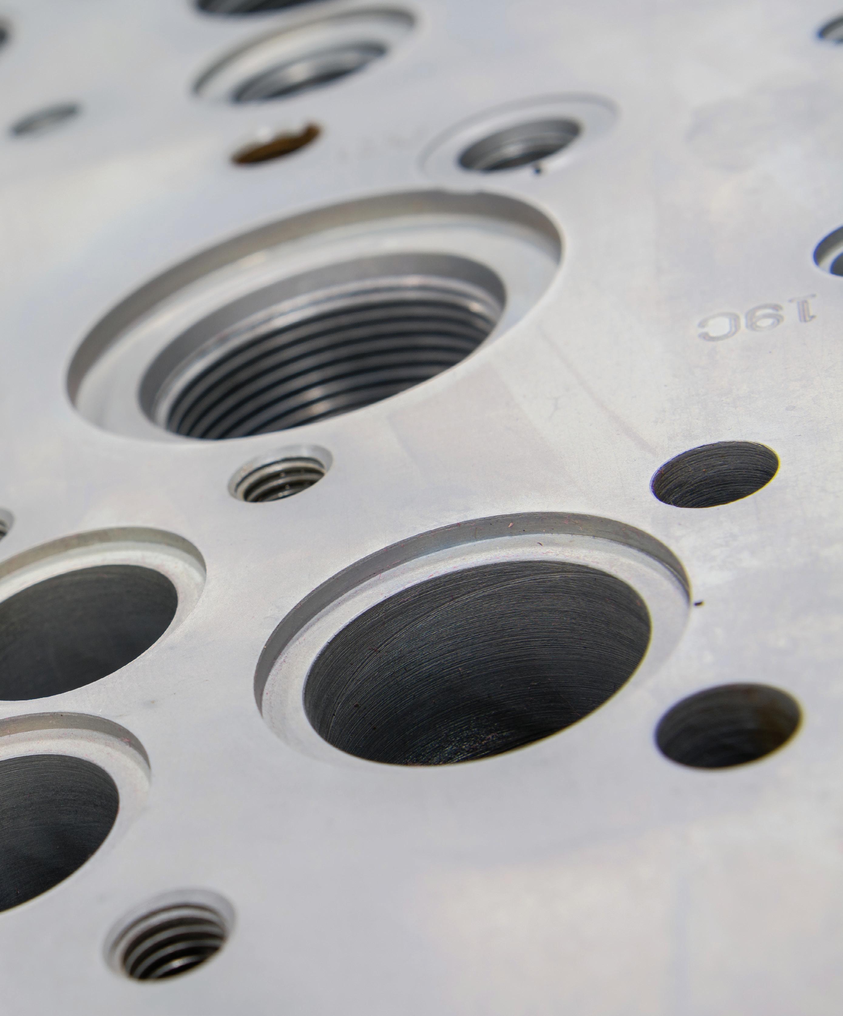
Figure 1. Hydraulic manifold. Courtesy of Adobe Stock
42-Size 6-Way cartridge cavities
shape is more straightforward than the multi-port screw-in cartridge valves. Without going into many details, logic elements are large 2-way, 2-position valves which use various pilot control functions, allowing them to mimic directional, pressure, and flow valves. There are downsides, however, such as the requirement for four valves to replicate standard 4/3 directional valves.
Why should you use HICs?
If manifolds are so difficult to manufacture, why should you choose them over separately plumbed components? Well, there is space efficiency — integrated hydraulic circuits take up less space than traditional hydraulic circuits because the cartridge valves are compact and installed directly into the machine block, reducing the need for external piping and reducing the overall size of the system.
a minute longer to remove and replace the coil(s). In addition, no electrical connections need messing with as the coil can remain wired, requiring only gentle placement out of the way until the valve is changed.
Because there are hundreds of available cartridge valves, integrated circuits offer the designer near-infinite combinations of sophisticated control options. From postcompensation to proportional control, there isn’t any machine outside the complexity of a manifold to handle. With the combination of advanced (and expensive) subplate-mounted valves, there is nothing you can imagine that can’t be created.
Stackable valve designs in bar manifolds
Complex manufacturing
Hydraulic integrated circuits are an effective and economical method to organize the valves of your hydraulic machine. Instead of plumbing together separate components throughout a machine, all the passageways and ports are inside a single piece of aluminum or steel. Special cavities are drilled into the block where the cartridge valve is inserted. The cavity looks like a mildly conical shape with cylindrical steps, and at each step is a cross drilling corresponding to each valve port (see Figure 2).
Although the complex shape you see can be achieved with myriad individual CNC drills and tools, specialized roughing and finishing tools achieve the
finished shape in two operations in a CNC mill. Although a standard drill may create the pilot hole for the roughing tool to more easily achieve its shape, you’d be surprised at how quickly the basic cavity shape can be hogged out of a billet of aluminum with the appropriate tool. You can see from Figure 1 how many holes may be drilled into a manifold. Integrated circuits aren’t limited to screw-in cartridge valves. The slip-in cartridge valve offers a similar benefit of clean installation while offering extraordinary flow capacity. Also known as logic elements, these valves may pass flow in the thousands of gallons per minute. They also find themselves installed into cavities, but the
Although the design and manufacture are bespoke, installing cartridge valves makes for a simple and quick process once the blocks are machined. The cartridge valves are inserted directly into the machine block and connected to the hydraulic system with minimal external piping. The time saved through installation on the machine requires fewer hoses and connections for the technician to plumb. Also, consider the reduced potential for leaks. With so few fittings and hoses, leaks are either internal or via the few externally ported connections.
Cartridge valves offer unmatched speed of maintenance, as well. Pressure and flow control valves require only a wrench to remove and replace in less than a minute. Solenoid valves may take only
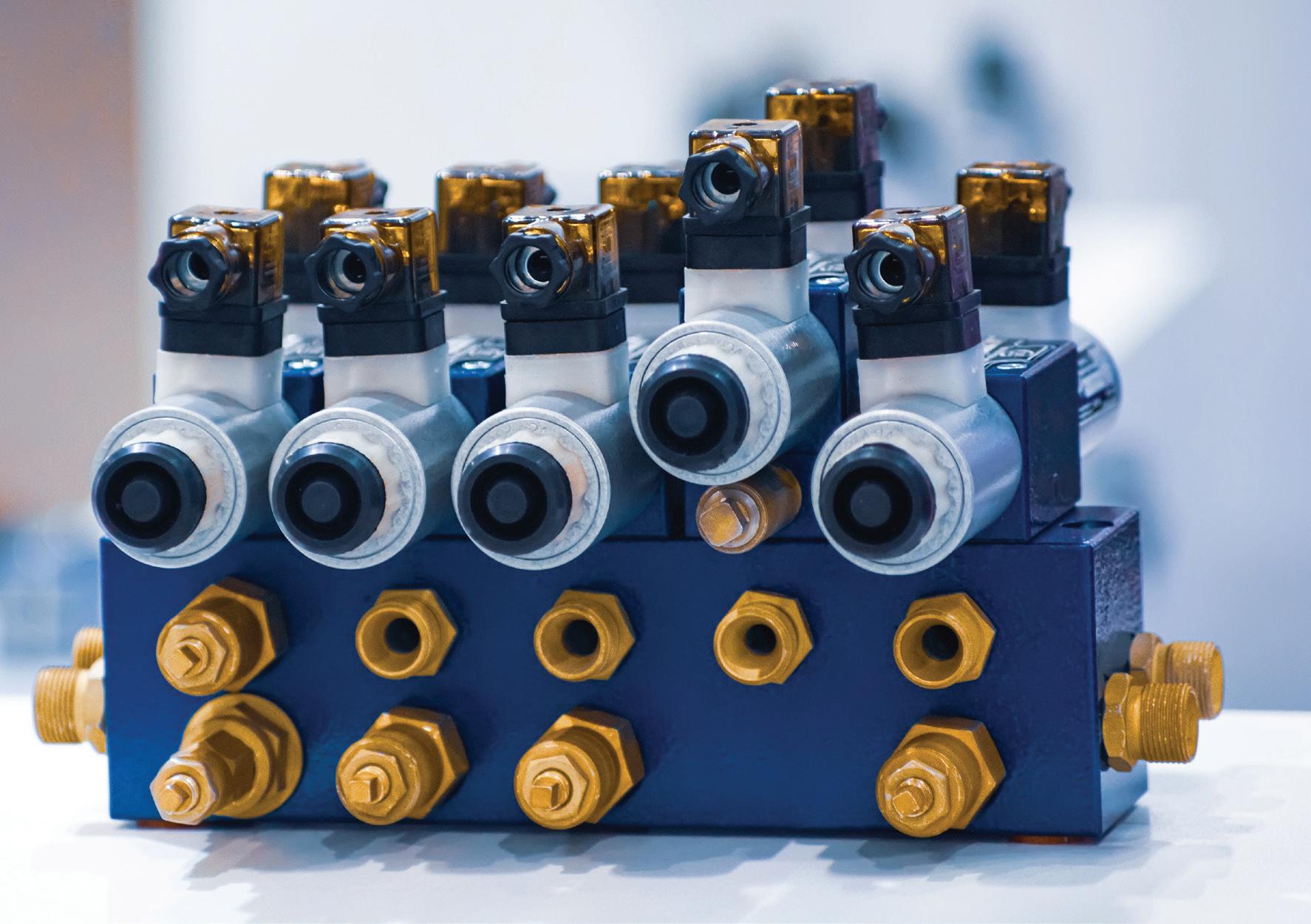
The mention of subplate-mounted valves brings to mind the stackable series very popular in the industrial hydraulic market (Figure 3). They are sometimes called ISO or CETOP valves because of the standards they’re based around, but what’s more important to mention for this discussion is their tendency to employ a different form of the manifold.
Bar manifolds are machined billets of aluminum or ductile iron that offer a readily available system of mounting valves to create simple circuits suitable for most circuits and machines. Machined from lengths of square bar raw material, with dimensions suitable for D03 right up to D10, they are made from 7 x 9 in. raw material.
With generally standard dimensions, valve interfaces and mounting holes, and with designated port locations, the manufacturing process for bar manifolds makes it quite
MANIFOLDS 30 FLUID POWER WORLD 4 • 2023 www.fluidpowerworld.com
Figure 2. Cartridge valve manifold schematic. Courtesy of Image HydraForce
economical compared to custom designs. Even with up to twelve sections or more run abreast, the difficulty scale changes little. Because most of the ports and drilling are perpendicular to the manifold surface, the only challenge comes from the diagonal drillings for the valve interface ports.
Creative fixturing in a CNC mill will allow the machinist to achieve the diagonal porting. Of course, care must be taken in the CNC operation to prevent side load on the drill, which could easily break, but any machinist worth their salt has the experience to select the correct speeds and feeds for such an operation.
Of course, the more sophisticated manufacturers do not waste time with multiple machine setups and instead use 5-axis machines that can complete an entire manifold in just two operations or less. If the threaded holes for the mounting feed are tapped only into the side edges, there’s no reason to remove the manifold to flip it to access the bottom. A 5-axis machine will be many times faster than a traditional mill but also costs many times as much.
Using a combination of stackable sandwich valves, 90% of the circuits any customer may need could be created in short work. Each stack starts with the valve closest to the actuators and builds to the directional valve on top. Locating pins sometimes ensure the valves are facing the correct direction, which is especially important for D03 valves, which have a symmetrical diamond-shaped port design.
The assemblies are held tight using four or six bolts. For smaller stacks, socket-head cap screws are preferred, but the hydraulic shop must stock various lengths. Not every valve in a stack shares the same thickness, so one set of four valves, for example, may have a different installed height from another set. For tall stacks, technicians cut the high-tensile threaded rod to the appropriate length and then top them off with stud nuts. Pro-tip: install a long-threaded rod into one hole of each valve section to act as a guide to help locate each valve as it’s installed, and then remove the rod to install the last bolt.
Bar manifolds may not offer the same space efficiency as custom-designed integrated circuits; they’re certainly a better use of space and plumbing than separately located valves.
Each valve in the stack eliminates what would have been previously two to six separately plumbed tubes, pipes, or hoses. Generally, sandwich valves eliminate leak points, but occasionally after decades of use, the O-rings that seal the ports between each valve may become brittle and leak. If leakage does occur, they’re effortless to replace.
Getting creative with your designs
Although circuit creativity offers fewer unique possibilities compared to integrated circuits, designs may still employ creative tactics outside the norm. For example, using an extra stack location in a bar manifold to create a mini circuit of pressure valves to offer creative control over the entire circuit is a distinct possibility. The system relief valve, an unloading valve, or even pressure compensators could be stacked together to control the pressure port of the entire manifold. Although most bar manifolds come with a port to install a screw-in cartridge valve, the performance of cartridge valves rarely matches a high-quality stack valve, especially regarding flow rate.
Bar manifolds come in either parallel or series circuits. Parallel circuits use a single pressure and tank drilling, extending the length of the manifold and providing each valve with the same access to pressure and tank flow. Unless an unloading valve is used, only closed-
circuit systems with pressure compensated pumps are suitable for parallel manifolds. For series circuits using fixed pumps, the flow path runs from the first valve station’s tank port into the next station’s pressure port. Care should be taken with series circuits because the P-to-T flow path occurs through the valve spool itself, limiting flow.
Although different in their own ways, each of the three manifold styles has much in common. This fact is not lost on manufacturers because the prominent players in the game make all three styles. As a result, manifolds are popular in hydraulics and have been a cornerstone of most hydraulic systems for the past couple of decades. FPW
Connect with thousands of engineering design professionals online.

THINK? WHAT DO YOU www.fluidpowerworld.com 4 • 2023 FLUID POWER WORLD 31
Figure 3. Solenoid valves on a hydraulic bar manifold. Courtesy of Adobe Stock
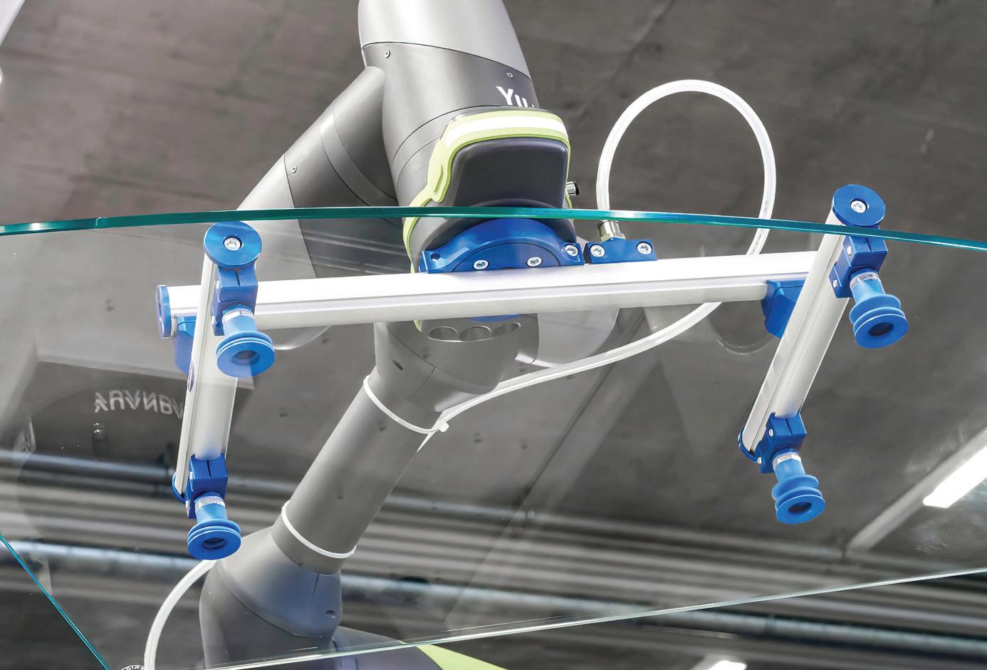
Get a grip with PNEUMATICS


advantages for machine and OEM payload handling. Designers find that modular gripper system kits are a versatile and rapid way to create handling solutions, with other benefits such as internal vacuum routing.


 Pat Phillips, AutomationDirect
modular vacuum kits 32 FLUID POWER WORLD 4 • 2023 www.fluidpowerworld.com
Manufacturing equipment, pick-and-place systems, robotics, and other machinery typically need to reliably grip products, materials, containers, or other objects so they can perform their functions. For robotic arm applications, this payload-handling hardware is often called end-of-arm tooling, but other equipment may simply use the term gripper. Many grippers use pneumatic- and vacuum-operated components to create the necessary forces and motions.
OEMs and machine designers invest a lot of effort to ensure these gripping interfaces perform reliably and are easy to maintain. Dropping a payload can lead to significant waste, and hardware failures introduce costly downtime. Customengineered gripping systems can theoretically be developed to meet any need, but the cost may be unacceptable, and the risk of design rework is high. In addition, many applications need the flexibility to handle many different types of payloads or address changing requirements.
For these and other reasons, a new concept of modular gripping systems provides OEMs and designers with better options. By starting with a modular system, designers can rapidly build a solution based on a proven combination of components and easily add other components initially or in the future as needed.
Advantages of pressure and vacuum


Compressed air and vacuum systems are complementary ways to engage a variety of gripping techniques. Air pressure can easily transport energy to any end-of-arm tool or machine location using various sizes of flexible hoses and fixed tubing or manifolds.

Pneumatic and vacuum systems can generate significant force, yet the air pressure can be regulated to adjust this force for more delicate operations. These systems are more economical and easier to work with than electrical or hydraulic equipment. Also, air pressure can create vacuum as needed using a vacuum generator, also known as a vacuum ejector. In many applications, it is only necessary to route one appropriately sized compressed air supply hose out to the gripper hardware. Then, manifolds and solenoids can operate devices, simplifying installation and maintenance.
Compressed air can be used directly to operate mechanical grippers or linear or rotary pneumatic actuators associated with other gripping mechanisms. This is suitable and even preferred for many types of payloads but requires accurate positioning, and it can sometimes run the risk of marring the payload or dropping slippery or smooth objects.
www.fluidpowerworld.com 4 • 2023 FLUID POWER WORLD 33
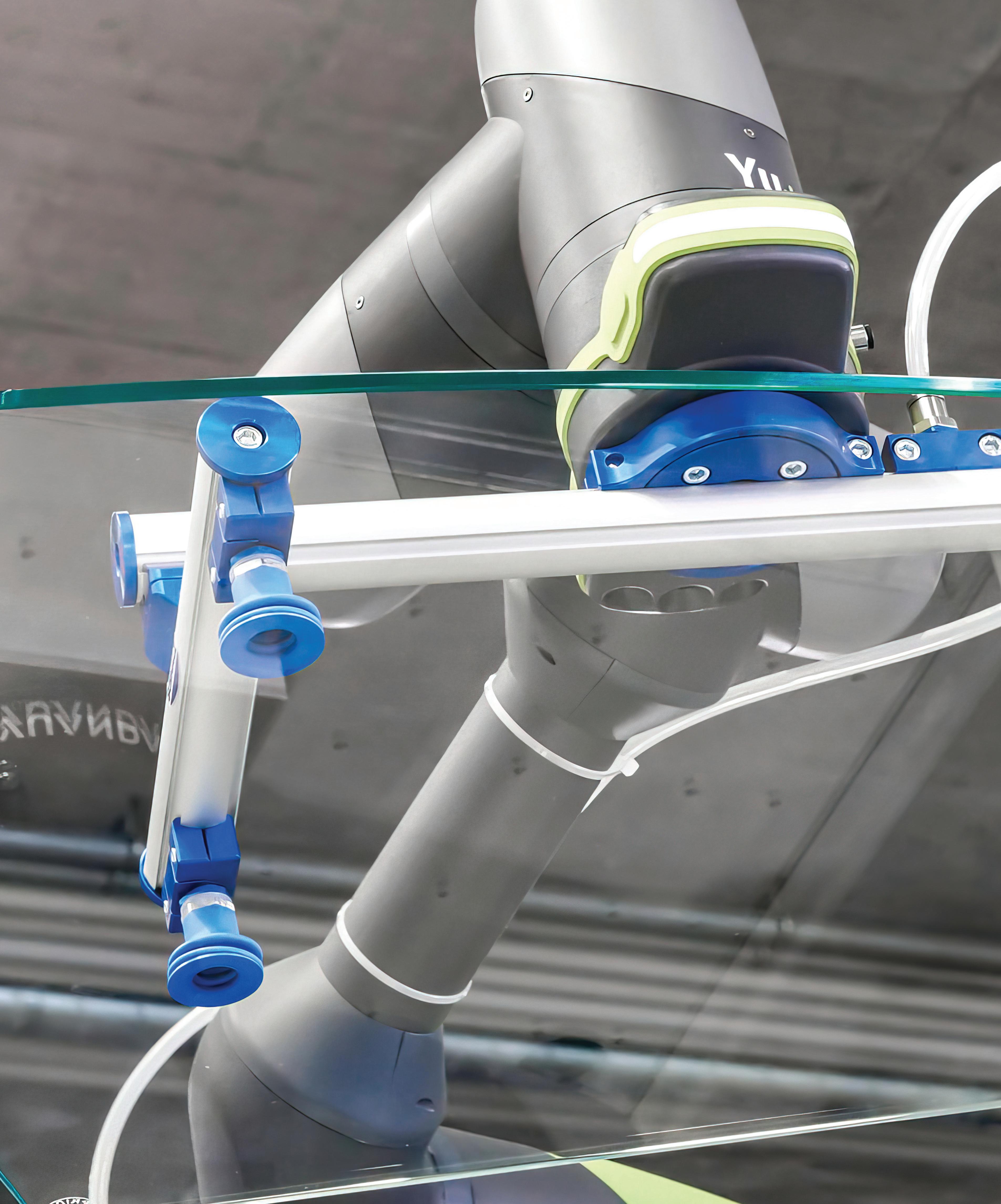
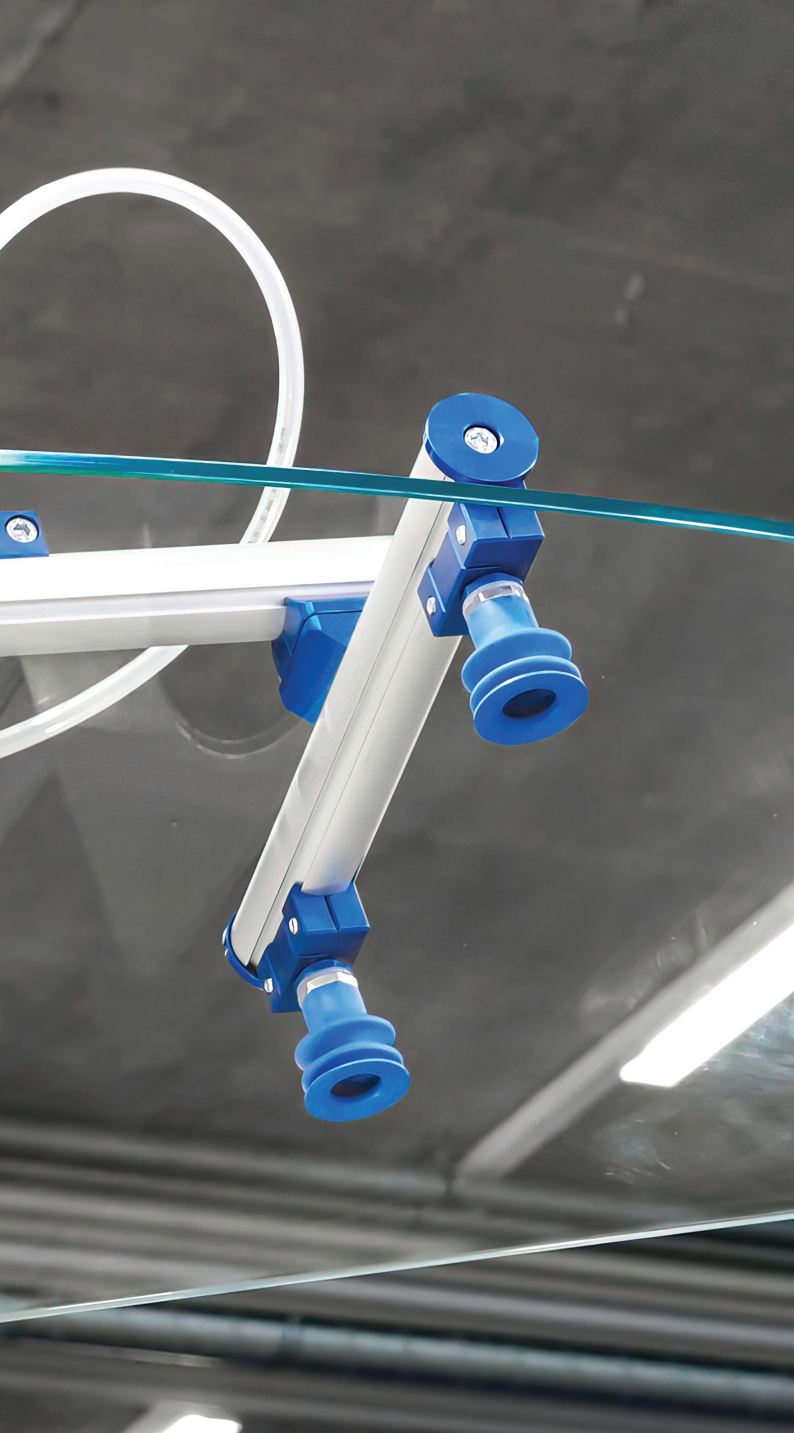
Many OEMs and machine builders prefer to use vacuum for gripping tools because of the strong available force with little chance of damaging or marring the payload. Courtesy of AutomationDirect and Schmalz.
Therefore, many designers rely on vacuum suction cups for gripping. Suction provides a strong grip with little chance of damaging the payload. It is particularly useful to grip flat areas of cartons, cardboard, and injection-molded parts, and multiple suction cups can be arranged on a tool to grip available payload surfaces, providing a degree of redundancy.
Suction cups are available in various sizes, configurations, and materials, each of which can be selected based on the payload. Suction cups may be flat, but bellowed styles also provide a degree of cushion and variability for the gripping action. Some typical materials are Elastodur, nitrile rubber, and silicone, which are selected based on elasticity, durability, and payload texture.

Arranged on a gripping tool, suction cups can be fixedmounted or installed on a spring plunger to provide additional flexibility for payload height variations. In some cases, one or more position sensors may be installed on the tool so that the automation system can

detect when the suction cup is in gripping range of the payload.

While these pressure and vacuum details are fairly straightforward, creating a framework or tool to support these grippers in the proper geometry is necessary, which can require significant design expertise.
Designing a support system


Gripping tool frameworks need to be strong enough to support the payloads and rigid enough to prevent flexing, which could cause grip failures or wear, yet light enough to avoid burdening the machine mechanism or robot supporting them. They also require a compact overall size envelope to prevent interference of the tool with the machine or payload sources and destinations.
Some designers might work with a fabrication group to create the framework from metal stock by cutting, welding, and fastening pieces, but this custom work limits the ability to easily make changes moving forward. Another popular approach for many teams is using T-slot aluminum
framing systems, which offer many configurations of material and fittings and are comparatively easy to assemble and modify.
A better hybrid solution has emerged for creating pneumatic and vacuum gripping tools that combine the benefits of standard framing systems with the convenience of standardized modular kits while adding benefits specific to vacuum distribution.
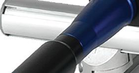
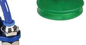
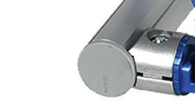
Modular gripper system kits consist of starter sets in popular configurations. They comprise dozens of parts, including aluminum structural profiles, joints, holders, and connections. Rated for small- to medium-sized applications up to about 140 active pound-force load, they are also available with flange adapters to connect the tool to commonly used robots. Designers select the kit that gives them the greatest head start, then add other components to complete the assembly by cutting, drilling, and attaching components with fasteners.
One important innovation of this modular system is that vacuum can be distributed internally through the framing profiles in addition to or in place of the traditional way of using external tubes, pipes, and hoses. This is because the framing profiles are hollow inside, and various sealing end caps and other connectors/adaptors are available to connect the vacuum supply and the vacuum cups to the framing.
The result is that users can create an exceptionally compact gripping tool, useful for applications with confined spaces, and can avoid problems
Gripping tools for machinery and robots can be rapidly assembled using modular gripper system kits. Each versatile kit includes dozens of basic components, and users can add or expand upon them. Courtesy of AutomationDirect and Schmalz.
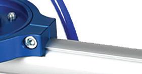
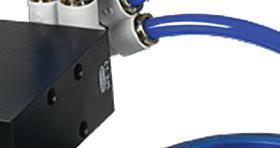
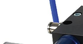
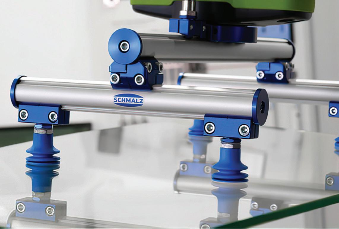
with tubing getting snagged in operation. Because the system can be streamlined by internal vacuum distribution, it is easy to keep clean and maintained. Vacuum distribution throughout the frame also makes adding or changing cup configurations in the future easy.
Standardization accelerates reliable gripper design
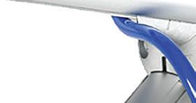
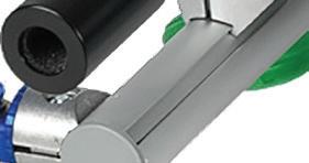
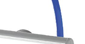
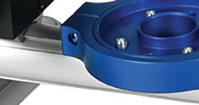


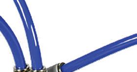

To avoid the costly and risky pitfalls of “reinventing the wheel,” engineers and designers usually prefer to build solutions based on standardized offerings to the greatest extent possible. For OEMs and machine designers, there is a great need to develop pneumatic- and vacuum-operated gripper tools for many equipment and robotics applications.
By beginning their designs with modern modular gripping system kits, end users can create versatile gripping tool configurations more economically and rapidly than with a completely custom approach. In addition, they can benefit from technologies such as internal vacuum routing while preserving the ability to modify the tooling in the future. FPW
PNEUMATICS
34 FLUID POWER WORLD 4 • 2023 www.fluidpowerworld.com
AutomationDirect automationdirect.com
One unique innovation of this gripper system is its ability to distribute vacuum internally through the framing profiles, providing compact and streamlined configurations that can be modified. Courtesy of AutomationDirect and Schmalz.
THERMAL BYPASS VALVE WITH INTEGRATED PRESSURE RELIEF

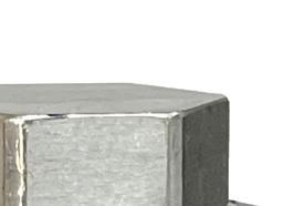
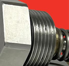
Our new thermal/pressure bypass valve option available for the brazed aluminum MAR and BOLR Series coolers allows you to have the lowest start up pressure in cold start situations to minimize pressure spikes in your hydraulic system.
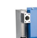
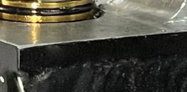
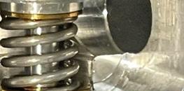
Temperature bypass is activated (closes) when oil reaches a defined set point of 110° F and allows full oil flow through the heat exchanger. When the oil is cool, the valve is open to allow a partial flow bypass. 60 PSI pressure relieve protects the system from over pressurization.
Features and Benefits

Thermal Bypass and Pressure Relief in One Valve

Optional Feature for MAR and BOLR Series

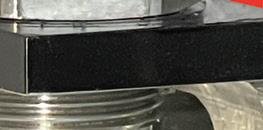
Internal Design Helps to Bring the System Out of Bypass Sooner

Pressure Relief Protects Against Flow Surges


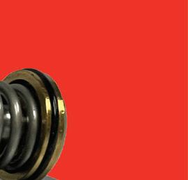
Eliminates the Need to Install External Components Saving Time and Money


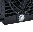
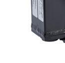
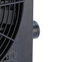
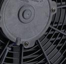

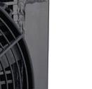
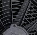

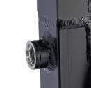
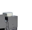
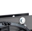


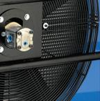
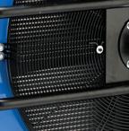

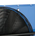
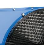


CONTACT US TODAY TO LEARN MORE!

ttp-sales@apiheattransfer.com +1.262.554.8330 We COOL what you POWER thermaltransfer.com BOL Series MAR Series

OFFSHORE WIND SEALING 36 FLUID POWER WORLD 4 • 2023 www.fluidpowerworld.com
Maximizing wind turbine efficiency through optimized hydraulic sealing Maximizing wind turbine efficiency through optimized hydraulic sealing
Eric Bucci, Global Technical Manager, Energy and Oil & Gas, Trelleborg Sealing Solutions
Today’s wind turbines are highly technical precision machines, utilizing the latest digital and computer technology to maximize the wattage from every wind gust. An average size two-megawatt wind turbine can generate enough electricity to supply about 1,000 households. Running 24/7 with an operational expectancy of 98% over 20 years, wind turbines function in extremely dynamic environments where reliability is paramount.


www.fluidpowerworld.com 4 • 2023 FLUID POWER WORLD 37
Advanced seal designs that prevent wear, increase service life, and reduce friction can ensure uptime in pitch cylinders and brakes.
Courtesy of Adobe Stock
With over 350,000 wind turbines currently in use globally, wind continues to be one of the fastest growing forms of renewable energy. In 2021, 93.6 gigawatts (GW) of new installations brought global cumulative wind power capacity to 837 GW, showing yearover-year growth of 12%1. The 2022 Global Wind Report notes that 557 GW of new capacity will be added in the next five years –more than 110 GW of new installations each year until 20262
A clean gust to zero
Clean electricity produced by wind power plays an important role in the future of sustainable energy. Wind turbines are key in working toward the International Energy Agency’s goal to reach Net Zero Emissions by the year 2050. This means all electricity produced will have zero carbon emissions and will help limit the global temperature rise to 1.5° C3
Contributing to increased wind energy
and sustainability, onshore wind is becoming increasingly popular as generation costs decrease. Close-to-shore offshore wind is receiving significant investment as well since turbines can be larger in size and generate more power. Floating offshore wind farms constructed on platforms tethered to the seabed can potentially allow for an even greater number of turbines in deeper waters further from shore.
Hitting the perfect pitch
As wind turbines have increased in size so has their output capability with pitch-controlled systems becoming the standard choice for efficiency gains.
With shaped blades that adjust and rotate to maximize productivity, active pitch control enables configuration of a wind turbine to operate efficiently at any wind speed. By actively managing the blade angle, operators can optimize the rotational energy from the wind, no matter the wind speed.

Housed within the wind turbine pitch actuator, a hydraulic pitch cylinder controls movement, slightly rotating the turbine’s rotor blades and adjusting the pitch for changing wind speeds. If wind speeds are slow, the pitch cylinder adjusts the blade angle to increase the blade surface area to capture the wind energy. As wind speeds increase, blades are angled to reduce the amount of surface area in contact with the wind, preventing excessive rotary speeds to protect system integrity. Drag at higher wind speeds also adversely affects system efficiency and changing the blade pitch can dramatically improve performance.
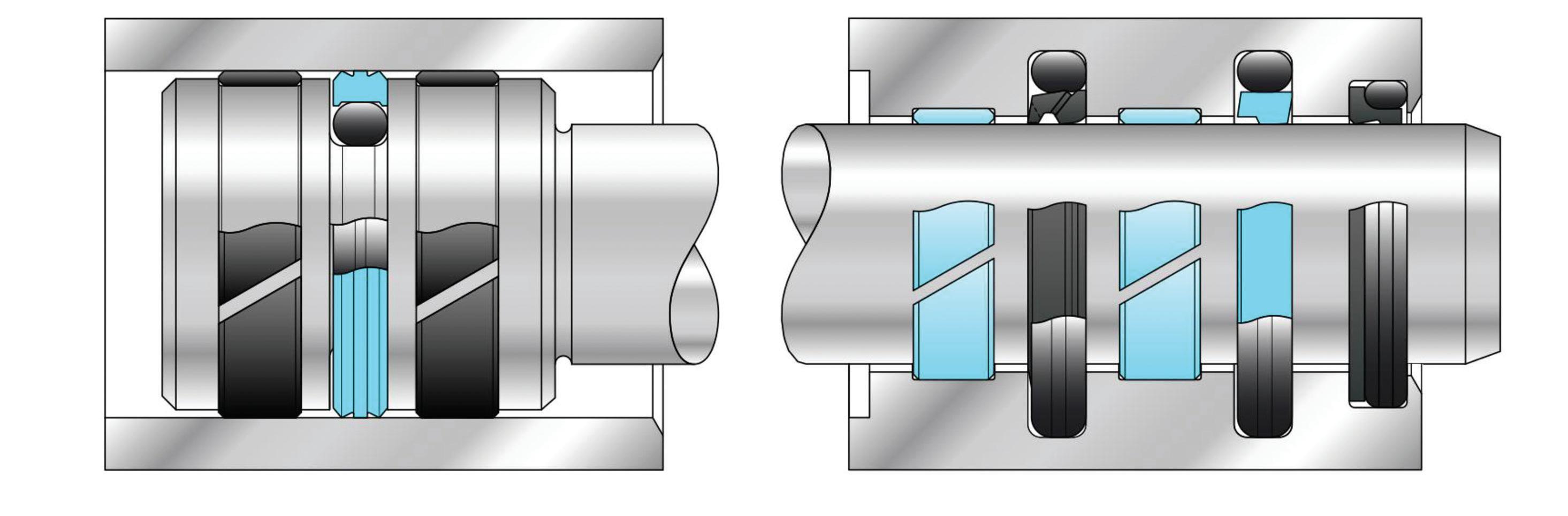
OFFSHORE WIND SEALING
38 FLUID POWER WORLD 4 • 2023 www.fluidpowerworld.com
A typical rod and piston sealing arrangement for wind turbines.
Typical wind turbine layout. All illustrations courtesy of Trelleborg
Challenging conditions
As wind turbines operate continuously, sealing requirements are extreme. The hydraulic system within the pitch cylinder uses a complex seal configuration to meet the dynamic demands of an active pitch control system. The sealing system must be capable of operating at pressures of 3,625 psi/250 bar with constant linear pressure on the rod and piston seals and differential side loads that control positioning.
While holding a turbine blade at an angle, on extension and retraction of the pitch cylinder rod, the sealing system must not exhibit any drift or slippage. This can result in the blade pitch deteriorating and drastically reducing efficiency. Seals must also easily release their holding position with minimum vibration and friction, or stick slip, and move in a smooth linear fashion. This requires low friction sealing materials.
In addition, seals must demonstrate minimal wear characteristics and facilitate dynamic movement that is continuous in short strokes. These, which occur on average 900 times per hour, can cause particularly aggressive wear as the seal cannot fully flex and relieve stress as it would in long stroke applications.
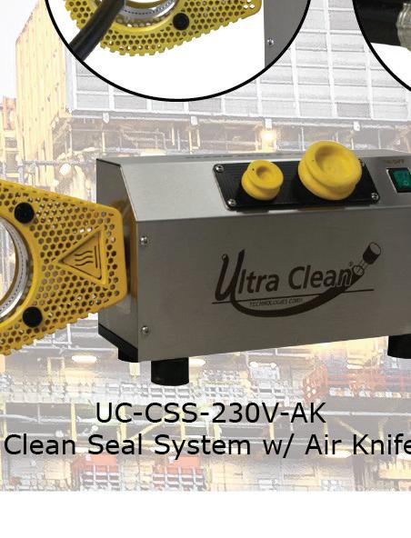
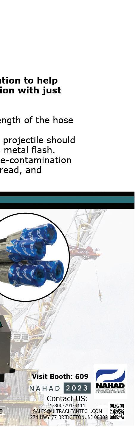
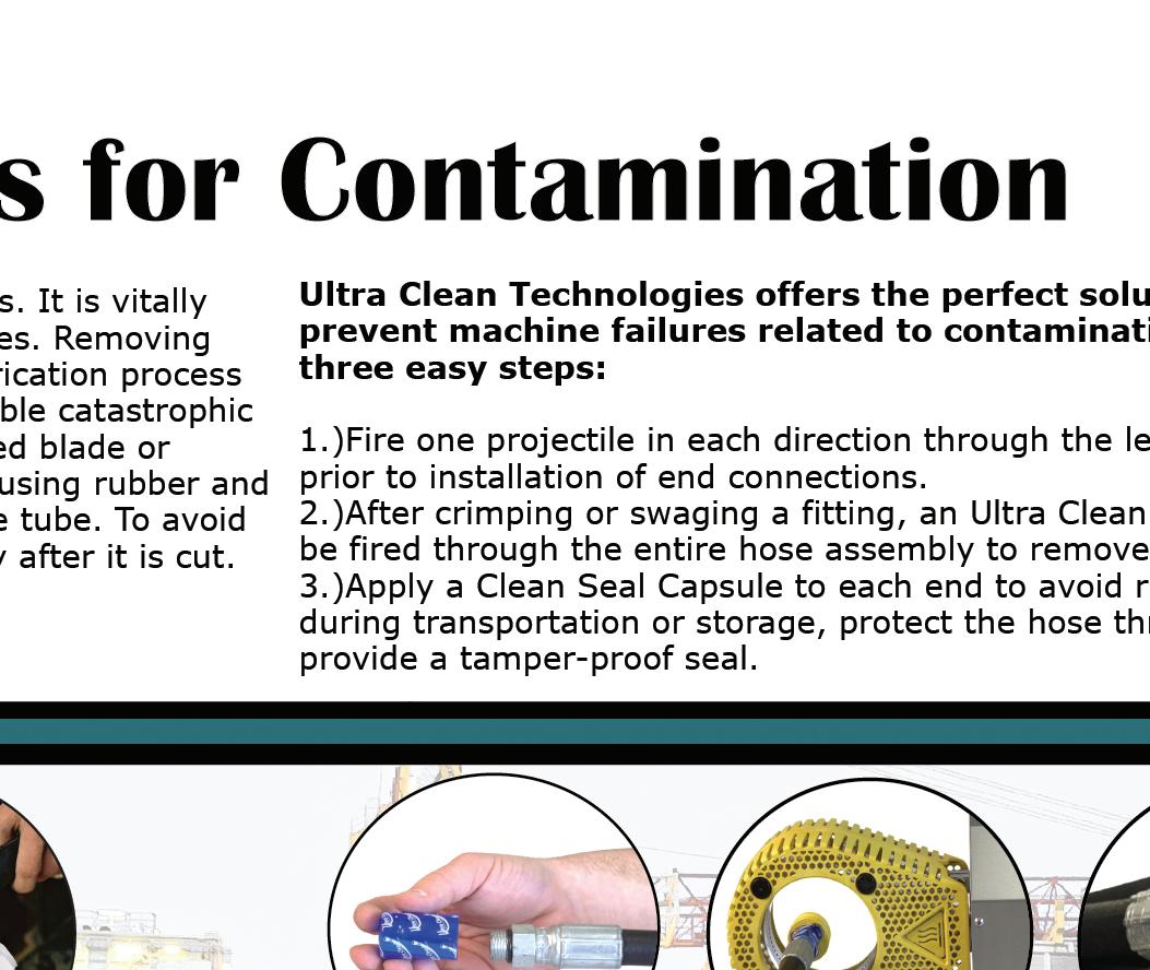
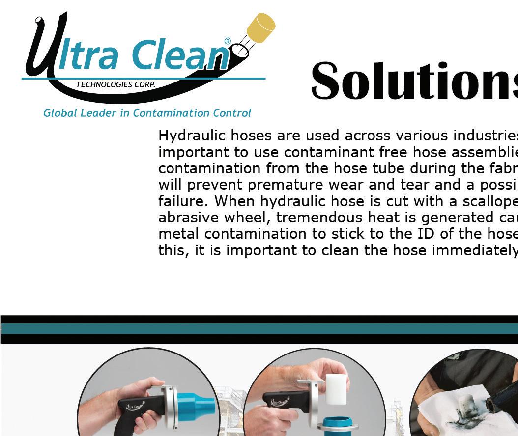
Operating companies require 20 plus years of service life for wind turbines while avoiding costly unscheduled maintenance. Standard hydraulic cylinder sealing materials may be insufficient; therefore, lowwear materials, such as polytetrafluoroethylene (PTFE) based compounds
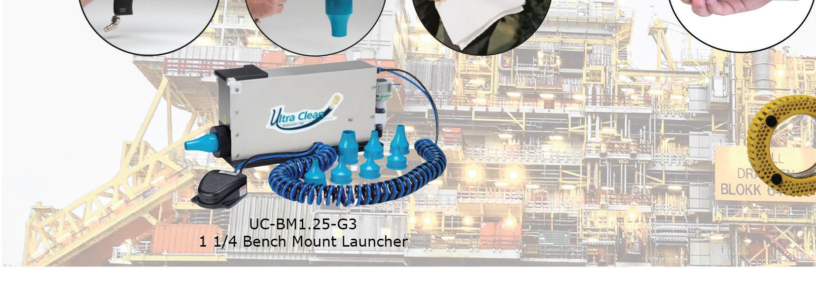
filled with anti-wear agents and a hard durometer, stable urethane, are needed to extend service life.
Standard polymer-based wear rings may also be incapable of reaching the desired extended life cycles. As an alternative, wear rings made of composite materials, withstand high loads and resist wear.
Seals used in wind turbines must be able to withstand cold temperatures as low as –22°F/–30°C as a standard, and even lower, down to –40°F/–40°C in very cold climates. When temperatures drop below these levels, the oil inside the cylinder can no longer work properly and requires warming with heating elements. Maximum temperature resistance for seals in wind turbine hydraulic cylinders is 140°F/60 °C. Above this, cooling systems are necessary so the oil does not become stressed, decreasing viscosity and carbonizing. In addition, actuator seals must withstand demanding conditions including high humidity, dirt particles, salt spray, and the rigors of wind and rain.
Optimized performance
Within a pitch cylinder is a complex arrangement of seals ranging from simple elastomer O-rings to advanced PTFE-based and engineered plastic designs. The seals within the hydraulics are integral to their performance and optimizing their life is critical to the long-term effectiveness of the total system.
www.fluidpowerworld.com 4 • 2023 FLUID POWER WORLD 39
An example of a sealing arrangement for a wind turbine is pairing Trelleborg’s Turcon Stepseal V LM, a single-acting O-ring activated seal made from PTFE-based materials engineered for dynamic applications, with Trelleborg’s composite Orkot Slydring, which prevents metal-to-metal contact between the piston and rod. Specially engineered configurations enhance lubrication, optimize friction
characteristics, and maximize service life, while preventing any external oil leakage.


To further extend seal life and performance, operators should incorporate an advanced corrosion-resistant coating to all dynamic seal running surfaces. Anti-corrosion coatings reduce the possibility of rust and pitting associated with ferrous metal surfaces. Polished to a seal supplier’s surface finish recommendation, these will
provide smooth hardware running surfaces to lower friction, reduce wear, and extend overall system reliability.
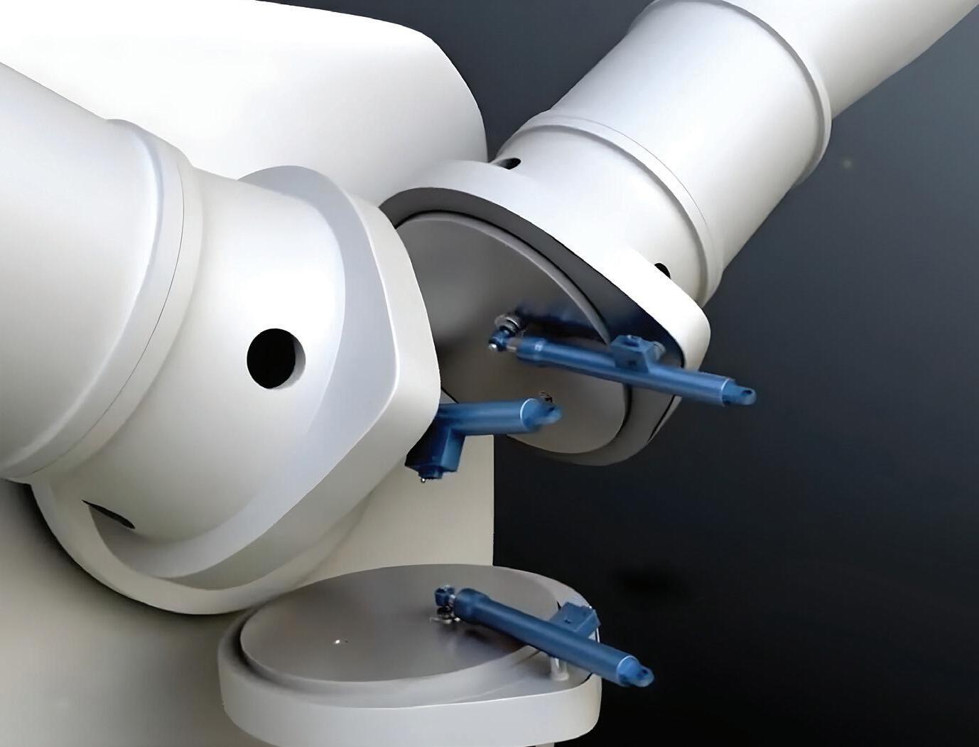
Pump the brakes
The maximum wind speed turbines can currently safely withstand is 55 miles/ 90 kilometers per hour. Above this, turbine blades can rotate too quickly and break apart causing catastrophic turbine failure. When wind speeds reach unsafe operating conditions and there is a risk of turbine overspeed, such as during severe storms, idling of the turbine prevents damage or failure. The main brake, often a hydraulic disc brake, assists in bringing the rotors to a standstill.
Equipped with plunger cylinders to hold the turbine tower in position, the hydraulically powered yaw or azimuth brake keeps the nacelle positioned against the wind. These systems typically use rod seals that have outstanding wear and extrusion resistance and long service life. For instance, Trelleborg’s Zurcon U-Cup
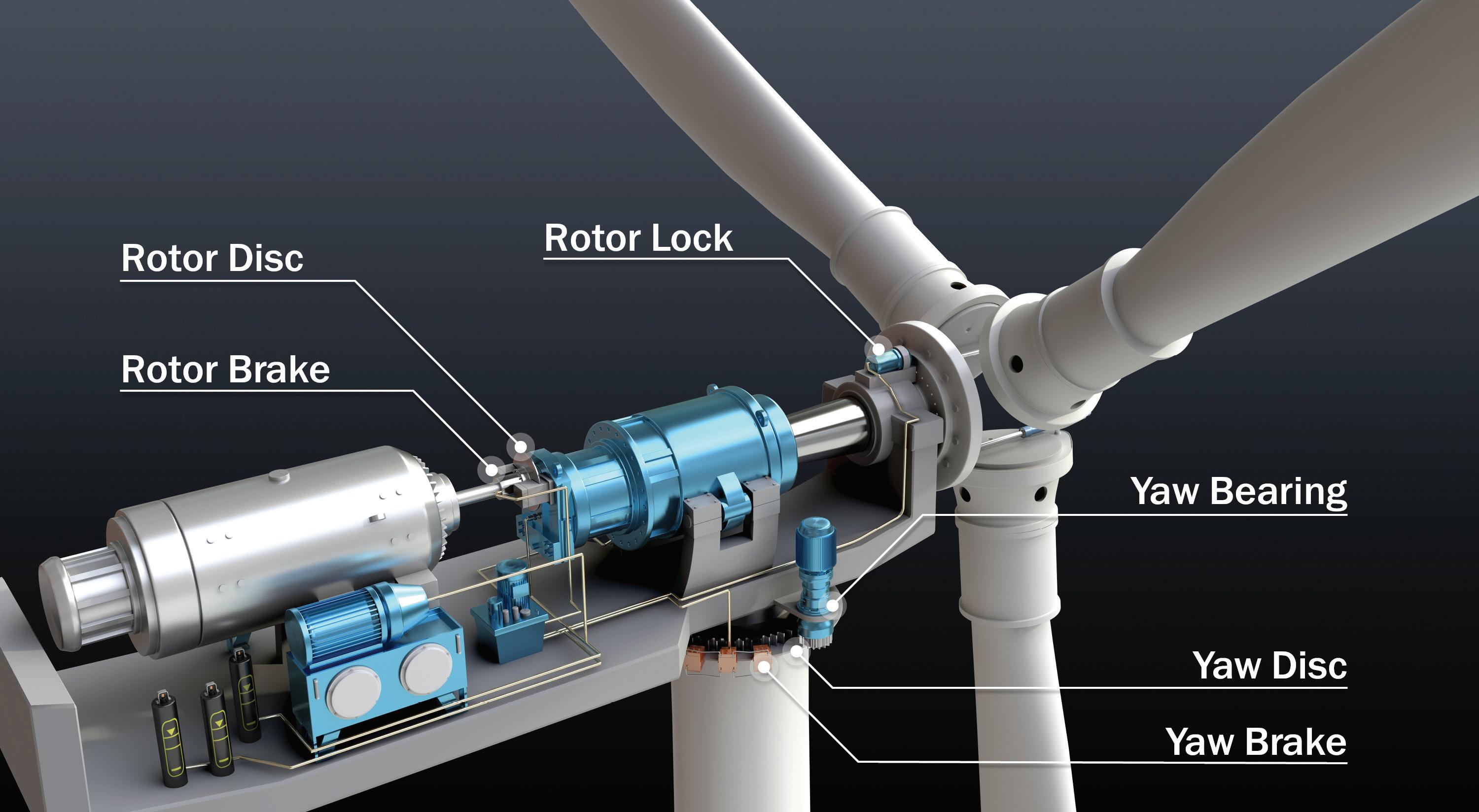
RU9 meets these requirements while being compatible with virtually all media and having a wide operating temperature range and low friction characteristics.
Conclusion
Optimizing hydraulic sealing can have a significant impact on wind turbine efficiency. By selecting reliable seals that prevent wear, increase service life, and reduce friction, operators can achieve technological advances in pitch cylinders and brakes, leading to reduced downtime and maintenance costs while ultimately improving energy output. As the global demand for clean energy continues to grow, wind power is poised to play an increasingly important role in meeting this need. By embracing innovative technologies and best practices, operators can maximize the potential of wind energy and pave the way for a more sustainable future. FPW

OFFSHORE WIND SEALING 40 FLUID POWER WORLD 4 • 2023 www.fluidpowerworld.com
Typical wind power braking components.
Trelleborg Sealing Solutions trelleborg.com
Typical wind power pitch cylinder arrangement mounted to the base of the blades inside the nosecone of a wind turbine.
THE HARDEST WORKING MACHINES


What are your machine challenges? You’ll find the answers with HydraForce – the world leader in precision hydraulic motion controls for mobile and industrial applications. Partnering with HydraForce, you’ll have access to unmatched engineering expertise; the industry’s broadest range of cartridge valves; custom integrated-circuit manifolds, and best-in-class remote-management solutions. Now you have the power to build a better machine. Visit HydraForce.com HydraForce.com.

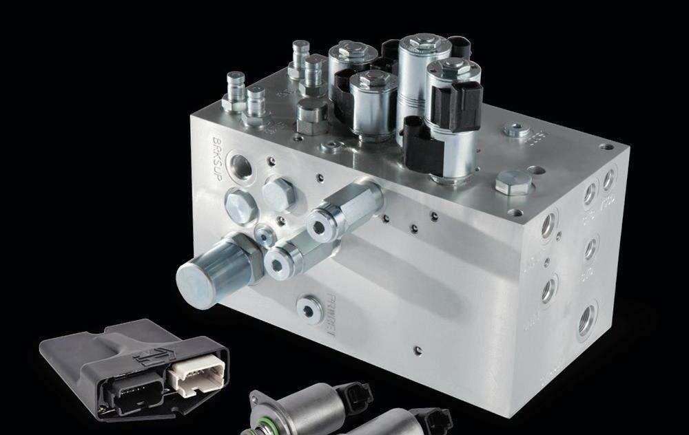


© 2023 HydraForce, Inc. LINCOLNSHIRE, IL, USA 847-793-2300 BIRMINGHAM, UK 44 121 333 1800 CHANGZHOU, CHINA 86 519 6988 1200 SÃO PAULO, BRAZ IL 55 11 4040 4087
HYDRAFORCE. RELY ON
OTC hones in on modern o shore tech

The Offshore Technology Conference returns May 1-4 at NRG Park in Houston.


 Edited by Mary C. Gannon, Editor-in-Chief
Although smaller in scope of exhibitors than in the past, the Offshore Technology Conference (OTC) 2023 continues to provide the most in-depth conference programming for offshore technologies. The technical program is complete with more than 300 technical presentations over the four-day event.


OTC showcases leading-edge technology for offshore drilling, exploration, production, and environmental protection. It is the world’s foremost event for the development of offshore resources. The conference attracts attendees and exhibiting companies from around the globe.
Earlier this year, the NFPA announced a commitment to more educational programming and networking at industry events. There are no technical presentations offered by NFPA members at the event, but the Fluid Power Forum will be exhibiting and hosting a networking reception for fluid power members on Tuesday, May 2 at 4 p.m. Fluid Power Forum is the podcast


that features interesting and innovative applications of fluid power (hydraulics and pneumatics). A key highlight at the Forum’s booth will be Texas A&M’s experience of combining human-powered vehicles with fluid power at the Fluid Power Vehicle Challenge Competition.
A 50-plus year tradition
Founded in 1969, OTC’s flagship conference is held annually in Houston. OTC has expanded technically and globally with the Arctic Technology Conference, OTC Brasil, and OTC Asia. OTC ranks among the largest 200 trade shows held annually in the United States and is among the 10 largest meetings in terms of attendance.
OTC is sponsored by 13 industry organizations and societies, who work cooperatively to develop the program each year. OTC also has two endorsing organizations and ten supporting organizations.
The event is currently at about 1,000 exhibitors and 24,000 attendees, who include engineers, technicians, executives, operators, scientists, and managers from almost 100 countries and all fields in the offshore energy sector.


42 FLUID POWER WORLD 4 • 2023 www.fluidpowerworld.com OTC PRE VIEW
Fluid power on display
Under the hydraulic systems category, 70 exhibitors are included, with about 60 key manufacturers returning to this annual event. Key fluid power exhibitors are listed to the right.
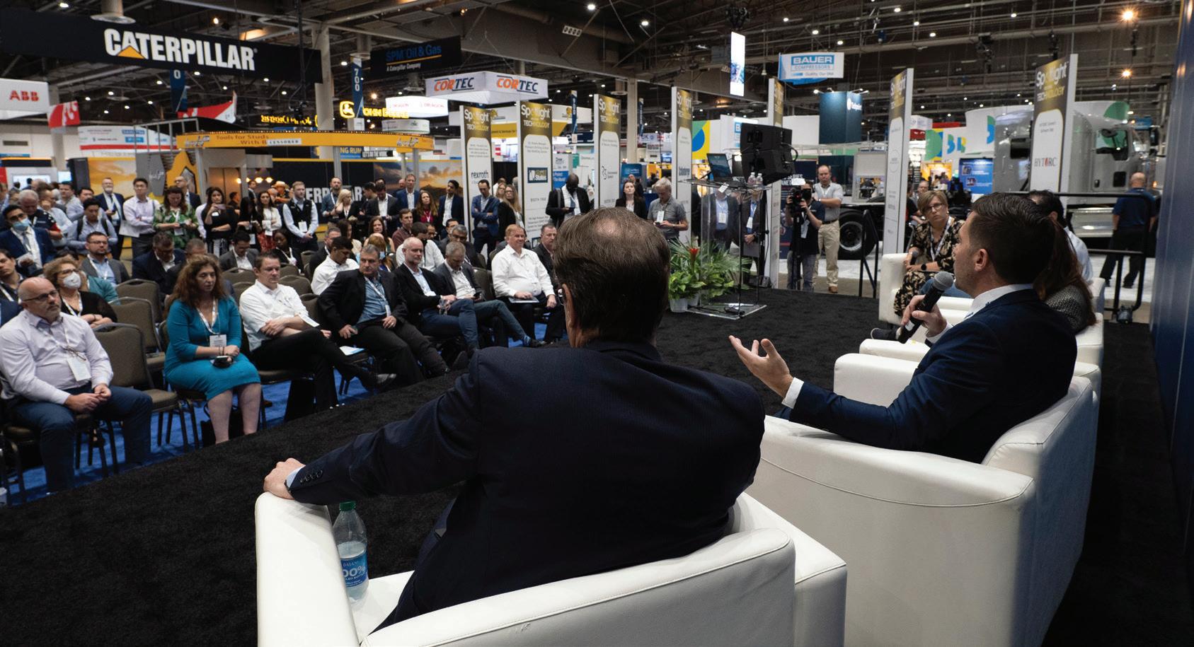
Ground-breaking innovations will be highlighted throughout the event, especially through the event’s popular Spotlight on New Technology Award, which is presented to OTC exhibitors who are revolutionizing the future of offshore energy through technological advancement and innovation. A total of 14 companies, including seven small businesses, were recognized this year for their breakthrough hardware and software technologies. Bosch Rexroth — who won in 2020 for its hydraulic Subsea Valve Actuator and 2022 for its SVA R2 electric Subsea Valve Actuator — will once again be recognized for its Hägglunds Atom motor, which is the world’s most compact powerful gearless drive that can be used to convert electric energy or diesel power to rotary motion. With compactness, reliability and long service life, the Atom supplies not only more revolutions per minute, but also far more power than motors of similar size.
The Hägglunds Atom offers a maximum torque of up to 13.6 kNm and an outer diameter of only 350 mm. It has a maximum speed up to 400 rpm, depending on frame size. All sizes allow maximum pressure up to and including its maximum speed, meaning an output power of up to 394 kW – with a motor weight of 52 to 102 kg. It is suitable for mobile, maritime and recycling applications. The compact and lightweight motor fits easily on a winch on land or at sea, for example. FPW
Visit
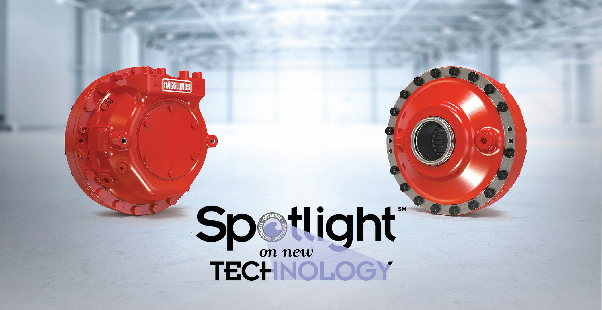
www.fluidpowerworld.com 4 • 2023 FLUID POWER WORLD 43 Exhibitors of Note Booth # Accumulators Inc. 1105 Alfagomma S.P.A. 3638 Altra Motion / Wichita Clutch 2005 Atlas Copco 1146 Bosch Rexroth Corp. 1914 Brennan Industries 2910 CEJN North America 901 Continental ContiTech Oil & Marine 2657 DICSA America 3120 Danfoss 3615 Douce Hydro SAS France 3145 Entro Industries 3508 Evonik Corp 1469 Famic Technologies Inc. 3307 Fluid Power Forum 718 Freudenberg Sealing Technologies 3823 G. W. Lisk Company 1309 GP:50 1255 HBC-radiomatic Inc. 4938 HETRONIC 1300 Hycom B.V. 1723 Hydradyne LLC 2779 Hydraulics International Inc. 3401 Hy-lok USA Inc. 2401 IFP Motion Solutions Inc. 3715 igus Inc. 2221 Innovative Hydraulics LLC 1308 Kaustubha Udyog (Orion Instruments) 1661 Kracht 2448 Lee Company, The 3331 Liebherr USA Co. 2959 MFP Seals (Martin Fluid Power) 2808 Midwest Hose & Specialty 2179 Moog / Focal 1249 NRP Jones LLC 714 PacSeal Hydraulics Inc 2505 Parker Hannifin Corp. 2839 Pennecon Energy Hydraulic Systems 2039 Pneumatic and Hydraulic 2755 PMC-STS Inc. 1457 Quaker Houghton 3209 Sauer Compressors USA 3514 SCF Sealing Technology INC 949 Schäfer Pumpen & Hydraulik GmbH 1441 SFP Hydraulics Inc. 1304 Smalley 1439 SPECIALTY FLUID COMPONENTS 2705 Spir Star Ltd. 2101 Stucchi USA Inc 3863 SunSource 1039 Swift Filters Inc 1760 TSUBAKI - KABELSCHLEPP 3100 Tube-Mac Piping Technologies Ltd. 3509 Wilkes and McLean Ltd. 4632 Wilson - Solutions In Motion 1101 Winters Instruments 4401
2022.otcnet.org to learn more and to register.
The Atom motor from Hägglunds is a recipient of OTC ’ s Spotlight on New Technology awards. Courtesy of Bosch Rexroth AG
CONEXPO GOES ELECTRIC
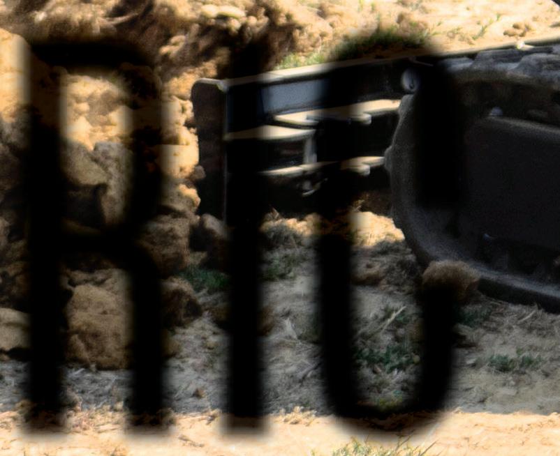

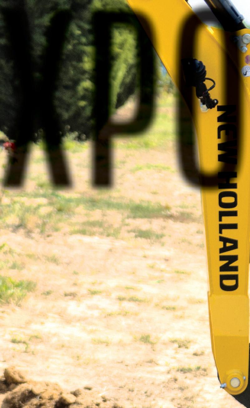
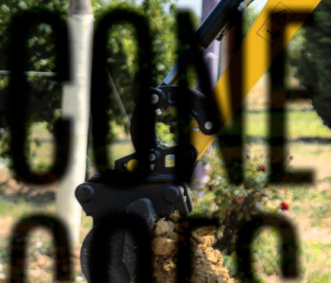
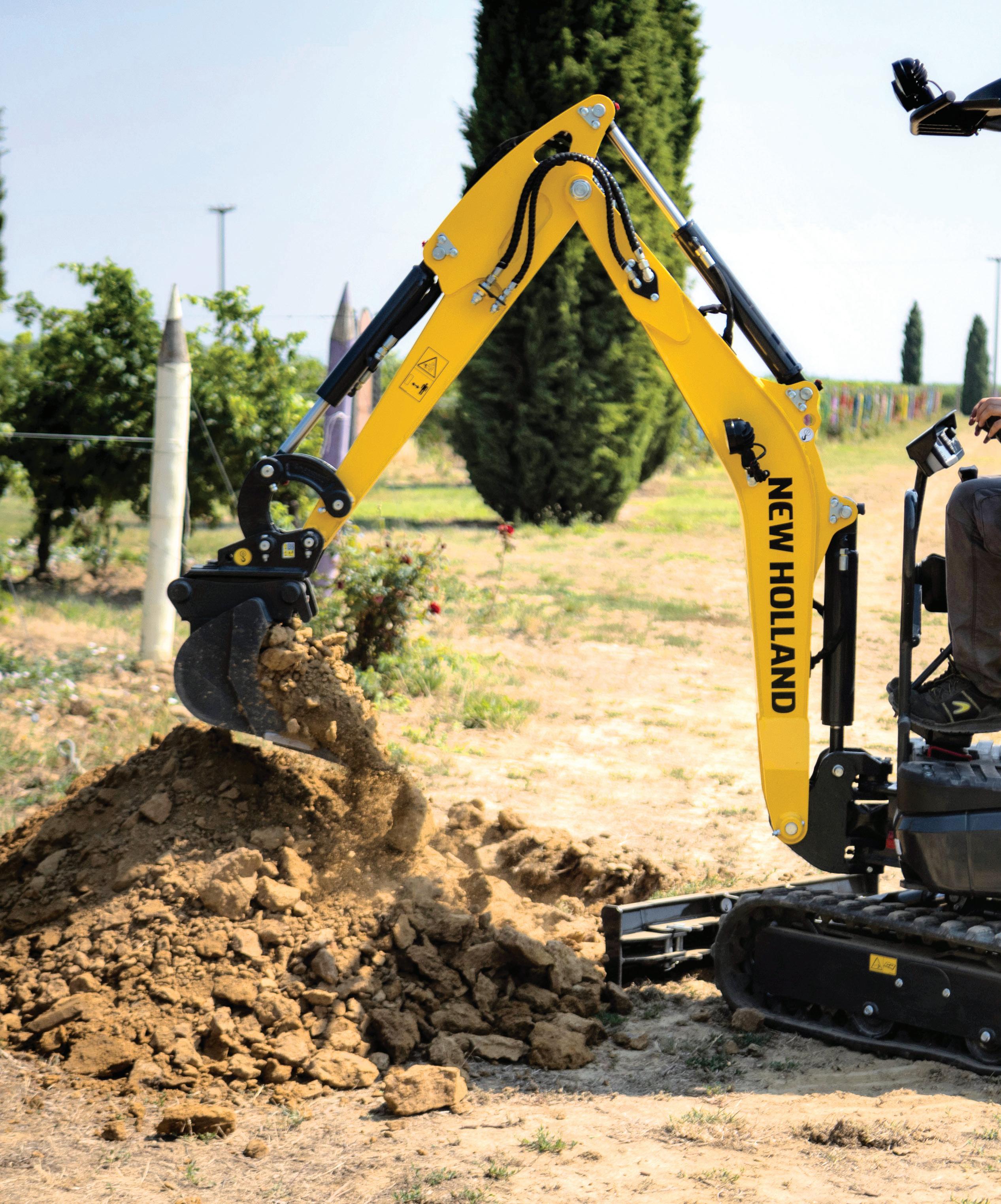
MOBILE HYDRAULICS 44 FLUID POWER WORLD 4 • 2023 www.fluidpowerworld.com
THEbuzz word heard throughout last month’s Conexpo/IFPE in Las Vegas was undoubtedly “electrification.” At every turn, construction equipment manufacturers large and small were showing off their latest battery electric machines, from excavators and loaders to backhoes and haulers, where the traditional diesel engine and fuel tank have been replaced by an electric motor and a bank of batteries.


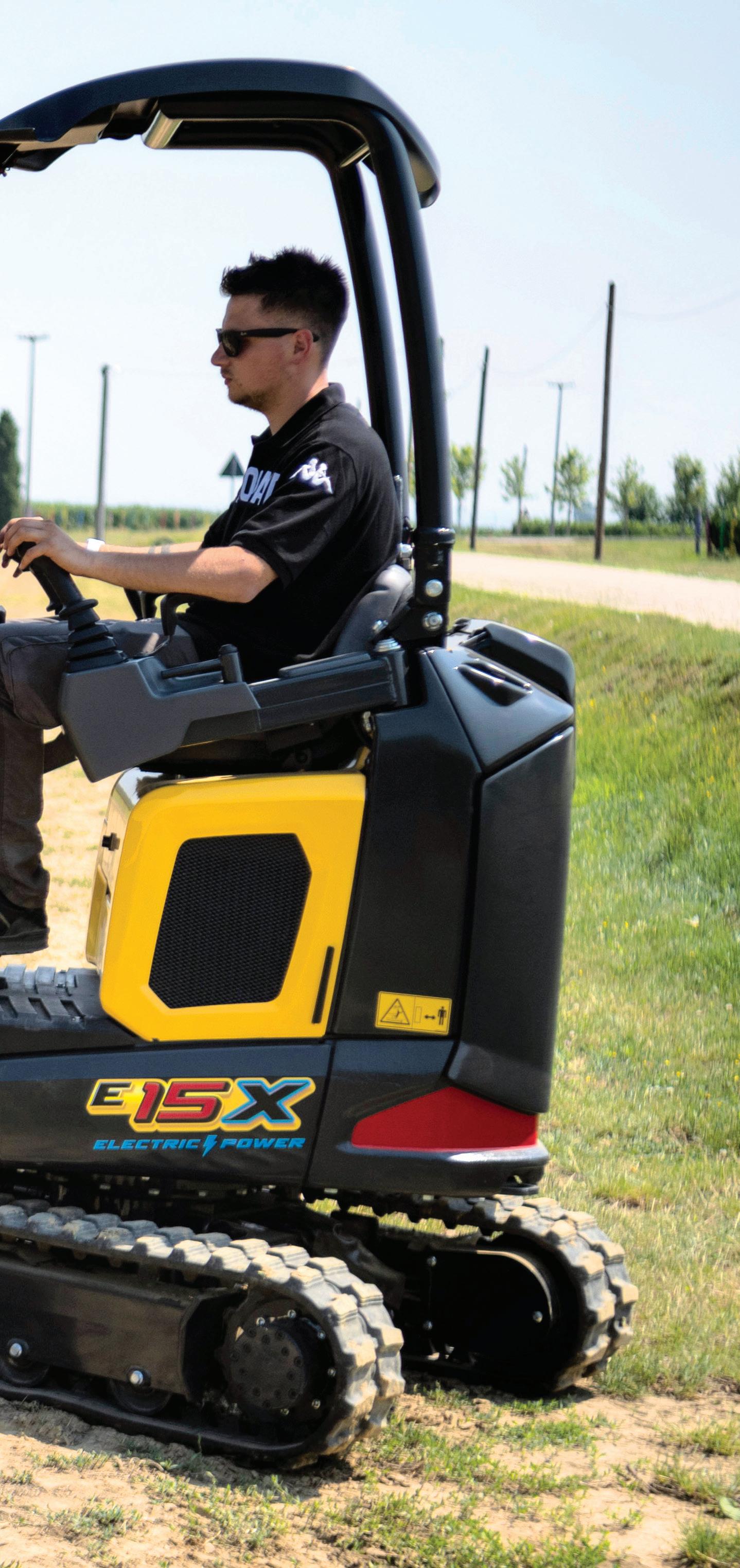
Many were prototypes, but some versions have been on the market for several years with sales running in to thousands of machines. Interest is gaining traction because these units emit no polluting exhaust, don’t contribute to global warming and run much quieter. And while the sticker price can be steep, compared to similar diesel vehicles, OEMs say lower operating and maintenance expenses make the equipment cost competitive over the long run.
For the most part these first-generation machines rely on conventional hydraulic components and circuits to power propulsion, lift, swing, and dump functions that match the performance and productivity of traditional equipment. But mobile-hydraulics suppliers are developing higher-efficiency systems that should raise machine productivity and extend battery life in the future.
Dozens and dozens of “fossil-free” machines were on display or operating to packed crowds, both indoors and on the outdoor lots. Here are just a few examples.

www.fluidpowerworld.com 4 • 2023 FLUID POWER WORLD 45
A WAVE OF BATTERY POWERED MACHINES IS SET TO MOVE OUT OF THE R&D LABS AND ONTO CONSTRUCTION SITES.
KEN KORANE, TECHNOLOGY EDITOR
New Holland displayed the E15X electric power mini excavator, its first machine in the EV segment.
Courtesy of New Holland Construction
MOBILE HYDRAULICS
EV launch


New Holland Construction, a unit of CNH Industrial, has launched its first commercially available EV machine — the E15X electric power mini excavator. “This is New Holland Construction’s first step into EV, a segment that’s going to continue to evolve and grow over the next decade not only for the industry, but for New Holland Construction,” said Tyler Mills, head of the company’s North American business segment. “The E15X electric power mini excavator is built to work in a variety of spaces — indoor, outdoor, tight, noise restrictive. It has a place from indoor construction jobs to landscaping, to utility digging and demolition jobs, and beyond.”
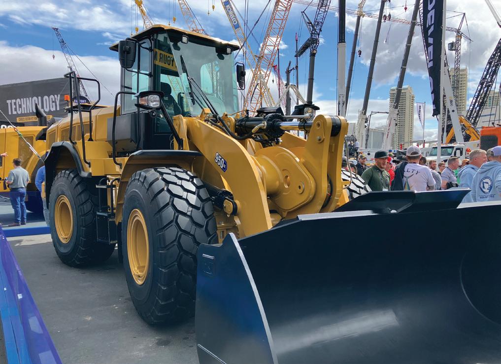
The E15X runs on a cobalt-free lithium-ion battery that powers a 21.5 hp motor, making it as powerful as the E14D diesel equivalent, which has a maximum rated hydraulic capacity of 200 bar (2,900 psi) pressure and 28 lpm (7.4 gpm) flow powering two separate circuits.


On a fully charged battery, the excavator can reportedly operate for up to eight hours. It can be recharged in 10 hours with a standard 110 V outlet or within an hour with its fast charge features. This gives operators the charging flexibility to fast-charge the excavator over a lunch break or slow-charge overnight.
The E15X produces zero emissions and uses eco-friendly biohydraulic oil to extend service intervals. The mini excavator runs noticeably quieter than similar diesel-powered equipment, making it optimal for indoor work or jobs with low noise level requirements.
The machine features eco, standard and power work modes with pre-set precision, normal, productivity and individual control modes, all of which can be independently adjusted. Power management software monitors oil flow and engine speed by detecting joystick movements and setting output speed to reduce loads on the hydraulics and battery.
The variable-width undercarriage can be narrowed to 31 in. and the height can be lowered to less than 4.9 ft by rotating the roll bar. This sizing flexibility contributes to the E15X’s utility as a tool for indoor construction sites, such as hospitals and office buildings.
Hydraulic-electrics


Komatsu showcased several hydraulic-electric machines and related battery technology at Conexpo 2023. The goal, said company officials, is to develop the technology and equipment to help customers reduce their carbon footprint and plan for implementing sustainable solutions, including electrification, and to make fleet management more efficient.
One featured product was the 20-ton PC210LCE electric excavator. With Proterra’s lithium-ion battery technology, the excavator has 451 kWh of battery capacity and an operating time of five to nine hours, depending on workload conditions.

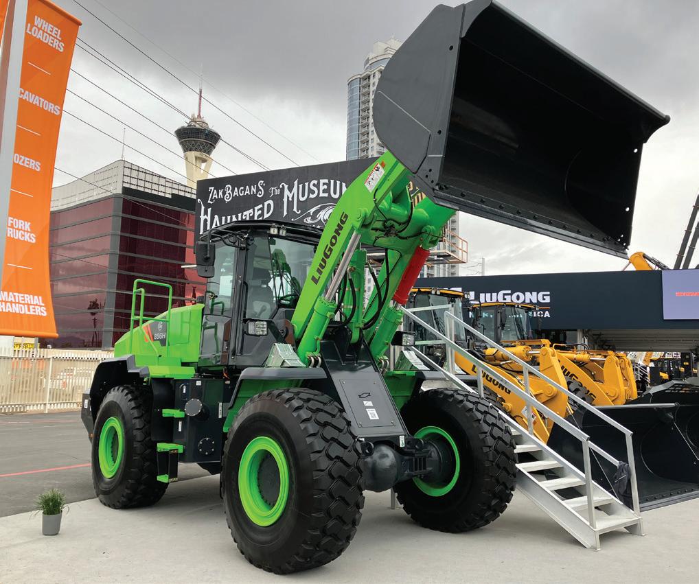
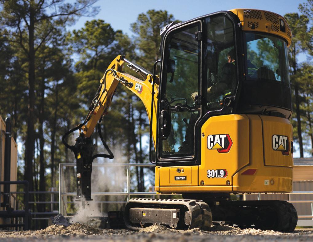
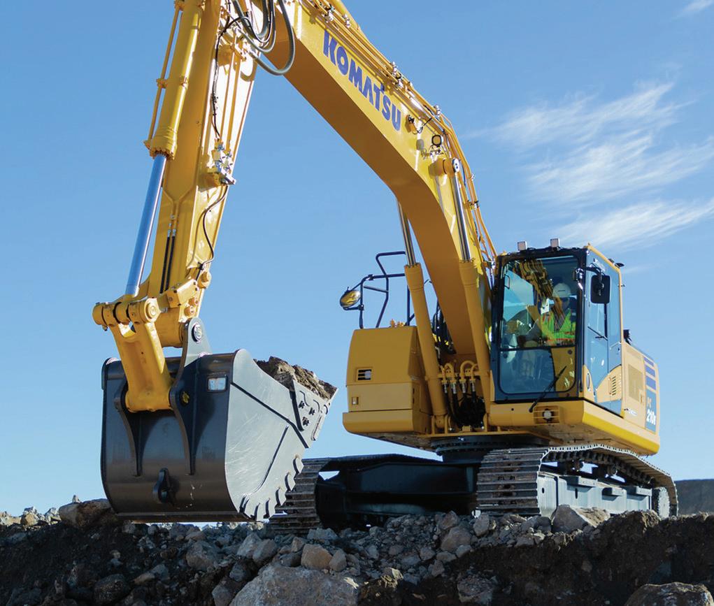
The PC210LCE was engineered for construction businesses that need a high-performance machine while cutting fuel costs and reducing carbon footprint. Designed to reduce operator fatigue with less noise, exhaust emissions and zero engine vibration, the PC210LCE is said to be ideal for use in urban areas and indoor environments and can allow for nighttime construction work both indoors and out.
The machine is based on the PC210LC, which relies on Komatsu HydrauMind (Hydraulic Mechanical Intelligence New Design) hydraulics, a closed-center system with load-sensing and pressure-compensated valves. It includes six selectable working modes. Variable displacement piston pumps supply boom, arm, bucket swing, and travel circuits. Maximum pressure is 372 bar (5,400 psi) and max flow is 475 lpm (125.5 gpm). Hydraulic motors power travel and swing functions.
At the show, the PC210LCE was displayed with Smart Construction Retrofit, an affordable guidance kit that gives operators and managers access to both 2D and 3D design and payload data to help drive accuracy, control load volumes and enhance operations. This technology upgrade is designed to improve grading performance and help drive productivity and profitability.
Also on display were the PC30E electric mini excavator, equipped with a 35-kWh battery
46 FLUID POWER WORLD 4 • 2023 www.fluidpowerworld.com
The Caterpillar 950 GC electric wheel loader features a 320 kWh battery and will be capable of operating up to six hours on a single charge.
Caterpillar’s 301.9 Electric mini excavator is designed to work for up to eight hours on a single charge, based on moderate operating conditions. Courtesy of Caterpillar
LiuGong exhibited the 856H-E MAX wheel loader, its newest battery electric vehicle for the North American market.
Komatsu’s 20-ton PC210LCE electric excavator is said to be ideal for use in urban areas and for nighttime construction work.
Courtesy of Komatsu
and a 17.4 kW electric motor, and the PC01E electric micro excavator powered by portable and swappable mobile batteries. They’re suitable for a diverse range of workplaces including operating indoors, urban construction, and landscaping. The PC210LCE, PC30E, and PC01E will be available in select markets in 2023.
Battery-electric prototypes
At Caterpillar’s Sustainability Hub, exhibit attendees viewed concepts of Caterpillar’s total site solution for energy transition, including four battery-electric machine prototypes. These machines are powered by Cat-designed lithium-ion batteries with a modular design that offers flexible configurations across multiple applications. The company has designed its own 48-V, 300-V, and 600-V batteries for the offhighway industry, leveraging its experience with gensets, locomotives, and large mining machines. The batteries offer flexible configurations across multiple applications, including the potential to reuse and recycle at the end of life.
Among the machines on display, the Caterpillar 950 GC electric wheel loader featured a 600 V, 320 kWh battery and will be capable of operating up to six hours on a single charge. The new medium wheel loader reportedly offers premium performance and simple-to-use technologies to help boost operator efficiency and increase productivity, while extended service intervals help lower maintenance costs.
The hydraulic system is based on that of the Cat 950 medium wheel loader. It uses a variable-displacement axial piston type pump with maximum output (@ 2,150 rpm) of 76 gpm and max implement operating pressure of 4,250 psi. Total hydraulic cycle time is 8.9 sec and rated breakout force is 40,690 lb-ft.
Other machines on view included the 320 Electric excavator, 301.9 Electric mini excavator, and the 906 electric compact wheel loader, designed to work for six to eight hours on a single charge. According to Cat, runtimes for the battery-powered machines are based on average, moderate applications. Runtime is influenced by a number of different factors, such as the type of application, temperature
of the environment, the load factor, ground conditions and operator techniques, said a company spokesperson.


The goal when developing these products is to ensure that customers do not experience any performance difference between battery electric and diesel-powered machines. Each model will include an onboard ac charger, which is best for overnight charging. A dc fast-charging option will also be available for charging during breaks. The 301.9 and 906 will be the first commercially available units in North America, with the 950 GC and 320 to follow in the coming years.
Mid-size excavator
Volvo Construction Equipment has been offering electric machines for several years, including small and medium-size wheel loaders, mini excavators, and now an electric road asphalt compactor. The company also announced an electric version of its 22-ton excavator, on display for the first time in North America, and set for customer pilots in the U.S.
The EC230E battery-electric excavator is considered a step up in an industry where electric vehicles thus far have mostly been compact models. The unit is based on the conventional diesel-powered EC220E, and will deliver the same performance, if not better,
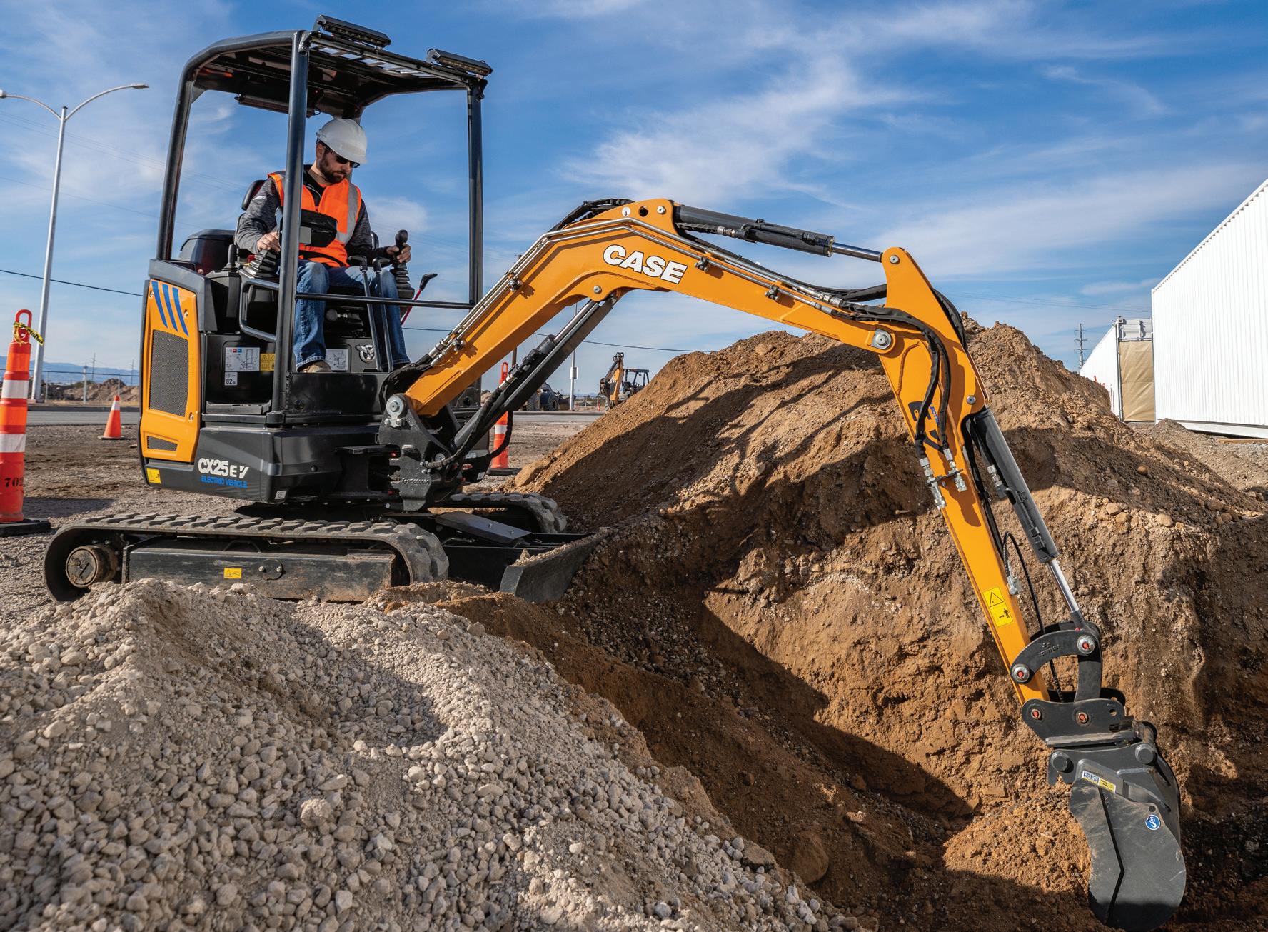
with the added benefits of zero emissions, low noise, and low total cost of ownership. The electric version is expected to reduce energy running costs by 60-70%, compared to dieselpowered machines.
According to company officials it can work a full day (eight hours) with high-power charging during a lunch break. It is fully compatible with a Combo2-Plug, a global standard dc charging system for electric vehicles up to 500 kW.
Based on the hydraulics of the diesel EC220E, the company says the electric excavator offers excellent controllability and efficiently uses energy. High pump input power permits highly responsive operation, resulting in greater productivity and fast cycle times. The main control valve, electronic control system, and an advanced Eco mode reduce power losses without curbing performance.
Important hydraulic functions include a summation system that combines the flow of both hydraulic pumps to ensure quick cycle times and high productivity. Others include arm priority for faster cycle times in leveling and for increased bucket filling when digging; swing priority, for increased swing force and faster simultaneous operations and enhanced controllability of the swing and boom operation – making it ideal for loading trucks;
www.fluidpowerworld.com 4 • 2023 FLUID POWER WORLD 47
CASE’s CX25EV electric excavator has a 110V/220V on-board charger and an external rapid charger. It reportedly provides enough power to work through a full eight-hour day.
Courtesy of CASE CE
a boom float function saves pump power for boom lowering for use by other operations; and a regeneration system that prevents cavitation and provides flow to other movements during simultaneous operations for maximum output.
Two variable displacement axial piston pumps provide the main supply, with a maximum for each of 207 lpm (55 gpm). Implement relief pressure is 363 bar (5,260 psi). Variable displacement axial piston motors handle travel functions, and a fixed displacement axial piston motor controls slew movements.
This is a general-purpose machine designed for extraction, earthmoving and grading for site preparation in the building segment, as well as waste and scrap handling in the recycling and waste segment.
MAX wheel Loader


LiuGong exhibited its newest battery electric wheel loader for the North American market, the 856H-E MAX, part of the company’s growing range of
electric construction vehicles.
“The industry is talking about battery electric vehicles at a greater volume than in years past,” said Andrew Ryan, President, LiuGong North America. “LiuGong is the world’s largest manufacturer of wheel loaders, so it makes sense for our company to lead the industry in the adoption and application of battery technology.”


There has been exponential growth in this area, with an estimated 2,000 of these units already operating worldwide in some of the world’s toughest conditions, he said. The 856H-E MAX is built for job sites where traditional combustion engines aren’t allowed or in fixed-site operations where investments in charging infrastructure make sense.
The new electric loader is said to be environmentally friendly while offering a competitive total cost of ownership. The 856H-E MAX consumes zero fossil fuel, produces zero emissions and generates significantly lower
noise and vibrations.


The unit features intelligent controls that includes loadsensing hydraulics, a transmission with electro-proportional valves for fast, smooth shifting, and independent control of the dual-motor drive for maximum hydraulic lift.
Its piston-type main pump generates 220 bar (3,191 psi) max pressure with a total hydraulic cycle time (raise, dump and lower) of 10.0 sec. The machine’s LiuGong Intelligent Auto Digging System automatically carries out repetitive digging cycles to reduce operator fatigue.
Powering the 856H-E MAX is a 432 kWh large capacity lithiumion phosphate battery from CATL. The machine is capable of 10 hours of working time for light applications and eight hours for heavy applications. It also features an Intelligent Battery Management System that can be fast charged in 90 minutes. The unit has an operating weight of 46,297 lb with a standard bucket size of 4.6 yd3 and rated load capacity of 12,786.8 lb.
Electrified mini excavators
With mini excavator demand continuing to grow exponentially (more than 400% overall since 2011) and strong demand in sectors like landscaping and underground utilities, CASE Construction Equipment is developing a diverse and comprehensive mini excavator lineup ranging from 1.5 to 6 metric tons. This includes the launch of two all-new electrified mini excavators.
The CX15EV is a 3,186-lb mini excavator powered by a 21 hp electric motor; and the CX25EV, available later in 2023, weighs 4,828 lb with a 27 hp motor. The lithium-ion battery featured in both machines is charged either by the 110V/220V on-board charger, or via an external rapid charger that can recharge a machine within 90 minutes. Depending on the application, both reportedly provide enough power to work through a full eight-hour day — all while delivering the core benefits of electrified construction equipment: no emissions, reduced noise, and less lifetime maintenance thanks to the elimination of the diesel engine.
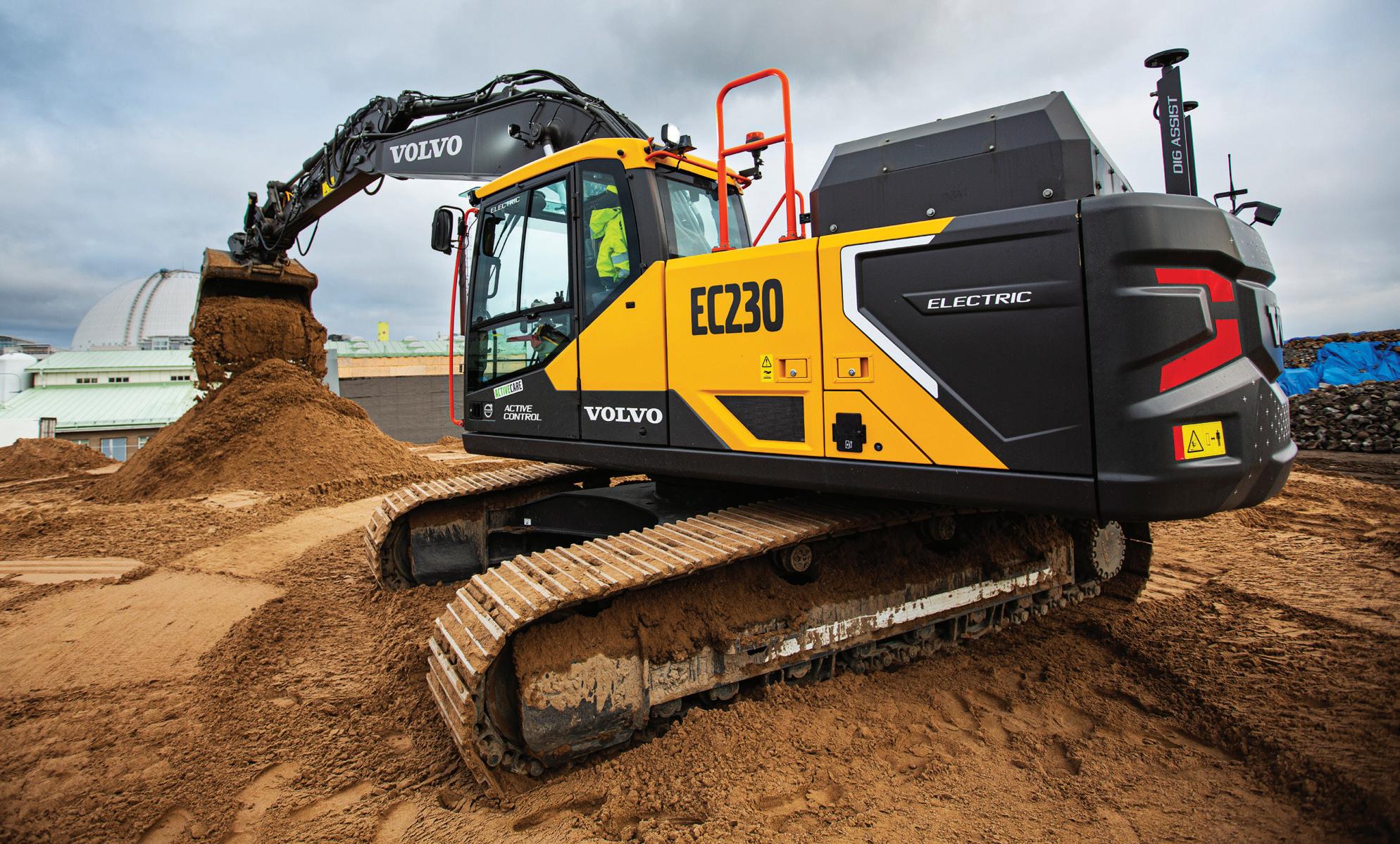
“Mini excavators are ideal for electrification because they go through varied work cycles throughout the day,” said Brad Mace, product manager, CASE CE. “Between access to power and the fast-charging capabilities of the machine with both onboard and external technologies, these machines deliver excellent runtimes and are sure to be ready to take on any task.”
The operator’s standard color LCD monitor provides battery information and machine settings, as well as customizable hydraulic proportional controls
MOBILE HYDRAULICS 48 FLUID POWER WORLD 4 • 2023 www.fluidpowerworld.com
Volvo’s 22-ton EC230E battery-electric excavator was on display for the first time in North America.
Courtesy of Volvo CE
and auxiliary hydraulics to tailor performance to a specific job. Each machine features three work modes — Power, Standard, and Economy — that match electric motor speed to the task, as well as the ability to adjust the sensitivity of the controls. For example, the operator can select specific responsiveness for six different bucket and boom actions, as well as swing, travel and blade functions.
A load-sensing hydraulic system further delivers smooth and powerful performance regardless of the application. Both machines feature standard 1-way/2-way hydraulics with an electronic detent hold to reduce operator fatigue, and an optional second auxiliary circuit (2-way only) adds more hydraulic options. The monitor can set and store flow settings for up to five attachments when switching between tools.
CASE is also focusing on connectivity, making SiteWatch telematics standard on each unit for optimal visibility into machine performance and greater collaborative fleet management. And each model can be outfitted with precision construction technologies to further improve productivity and digging quality.
Alternative power


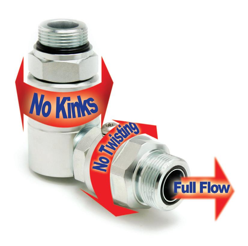
Hyundai Construction Equipment Americas demonstrated working prototype models of electric-powered equipment, including an R18E compact excavator. The two-ton-class
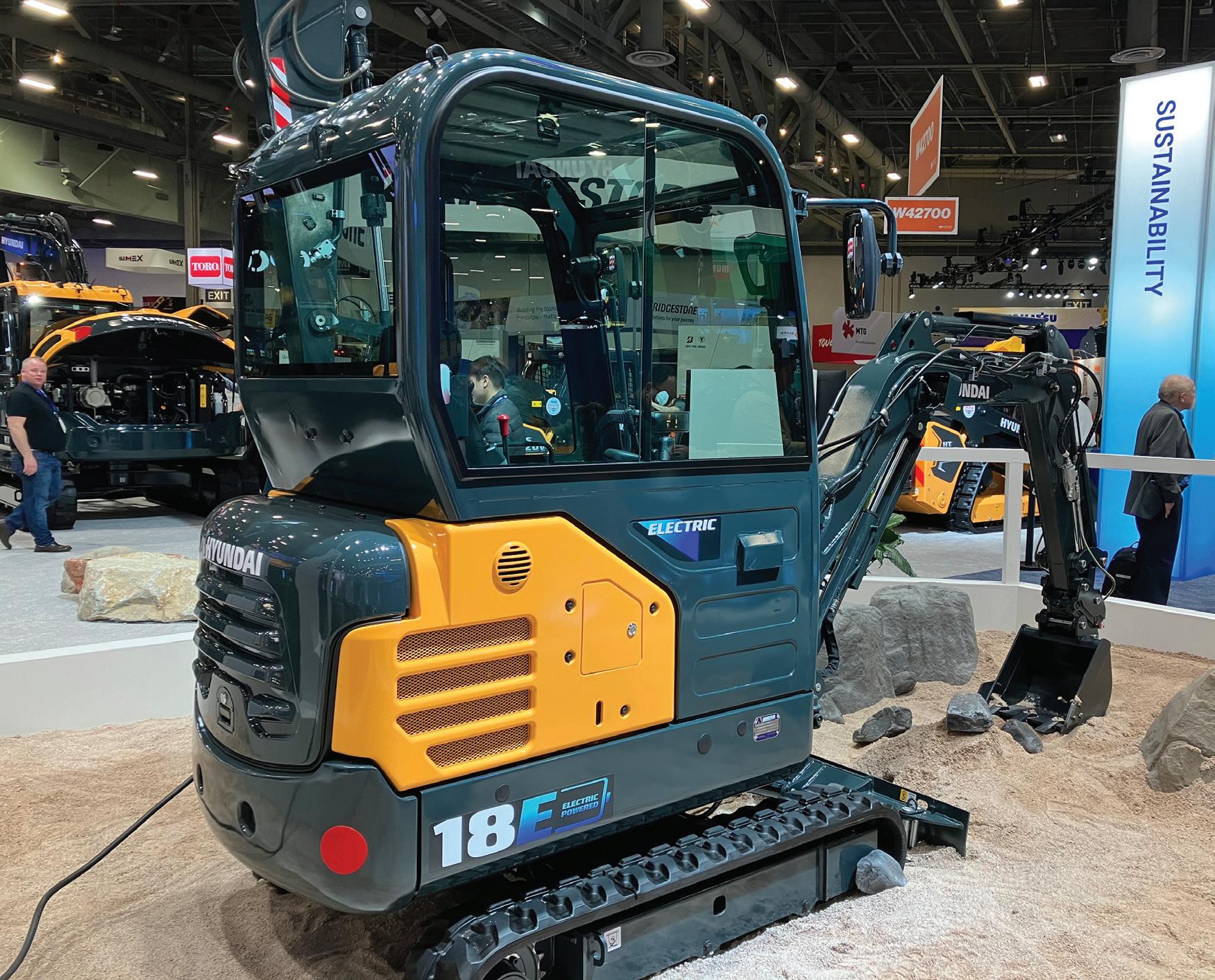
machine is designed for use both indoors and in urban settings. Offering power and productivity equivalent to the diesel-powered Hyundai R17Z-9A compact excavator, the R18E is said to be 60% more energy efficient, while providing a variety of benefits, including no carbon emissions and quiet operations — it generates just 70.1 dB of sound.
With an operating weight of 3,800 lb, the R18E is powered by a 20.7-kWh lithium-ion battery pack paired with a 13-kW (27-kW peak) induction-type electric motor. It can run up to eight hours on a full charge and can be fully recharged in five hours using a 220V supply.
The electric motor drives the machine’s hydraulic pumps in the same manner as in a conventional diesel model. The system includes variable-displacement pumps (max flow of 18.8 lpm/5 gpm) with implement relief setting of 210 bar (3,000 psi). A gear pump supplies the pilot circuit. Two-speed axial piston motors with planetary reduction gears power the hydrostatic travel drive; and axial piston motors direct the swing function. Hyundai CE is planning to launch several electrified models and sizes in the near future that will match level of performance of diesel-powered machines while reducing their environmental impact. FPW
Simplified hose configuration, less hose and adapters combine to reduce repairs and downtime, cutting the overall cost of hydraulics. 1-763-784-5531 www.SuperSwivels.com No Kinks No Hose Twisting Full Flow Quality Products Made In The U.S.A. Patent No. 5547233 Fax: 1-763-784-7423 Email: sales@superswivels.com Available In BSPP Hydraulic Live Swivels Inline & 90° Heavy Duty Ball Bearing Design • Also In 304 & 440 Stainless Steel • Rated To 10,000 P.S.I. • Heat Treated • Custom Design & Sizes Available • Rebuildable Ball Bearing Design • Full Flow —Low Pressure Drop • Superior Quality Alloy Steel • Side Load Resistant Sw i tc h Y o u r S w i v ®le S w i t c h Y o u r S w i v ®le 4 • 2023 FLUID POWER WORLD 49 Hyundai’s two-ton
is said to be 60% more energy efficient than a comparable dieselpowered machine.
R18E compact excavator

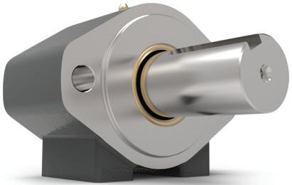

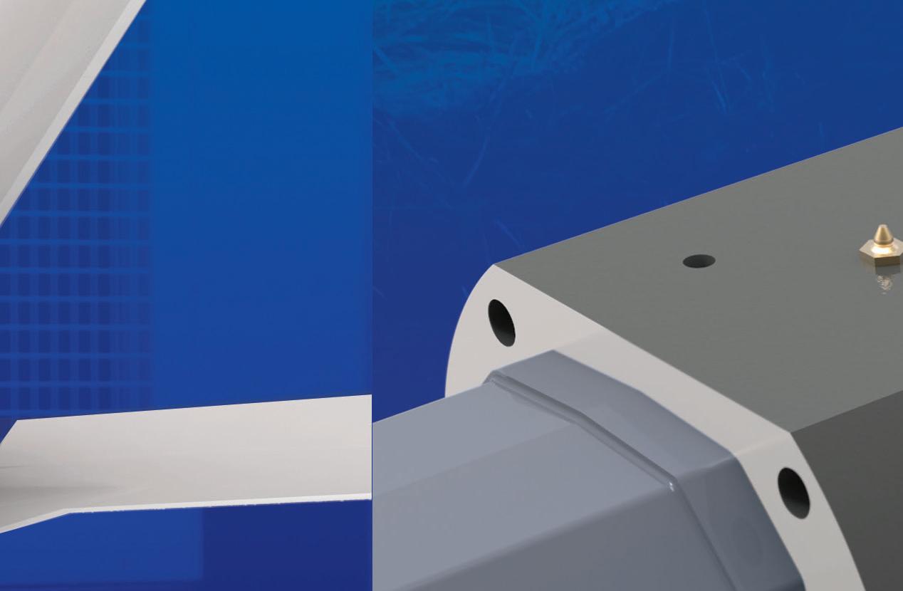
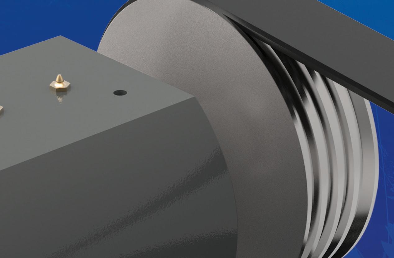
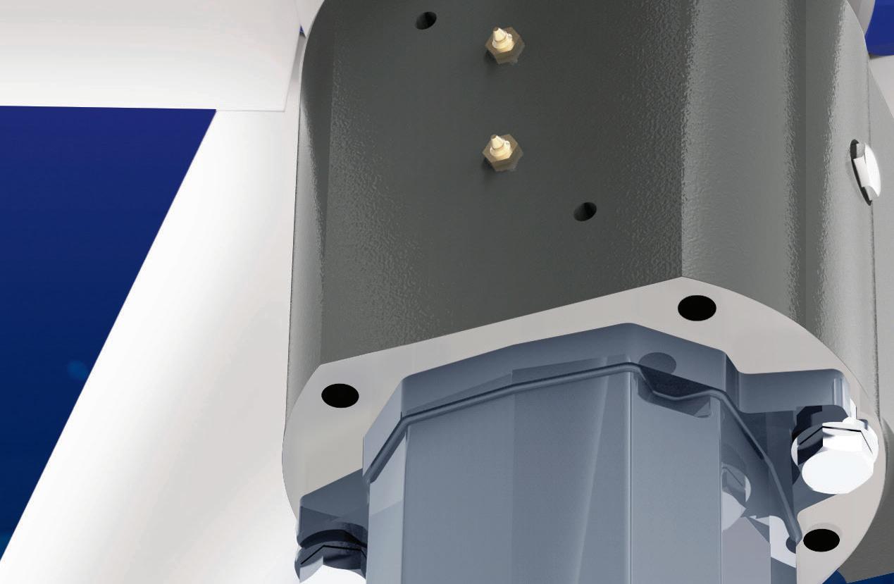


Overhung Load Adaptors • Provides Radial and Axial Load Support • Extends Motor/Pump & System Lifetime • Seals Out Dirt and Contamination • SAE A-F and non-SAE Mount Options • Standard Models / Fully Customizable • Engineering Assistance / Fast Delivery www.zero-max.com 800.533.1731 RELIABLE.ROBUST.AVAILABLE. RADIALRADIALOVERLOADS LOADSUPPORT AXIALLOADSUPPORT
Multiplate system
DL Series Plugs
Heavy-duty dual hydraulic hose reel
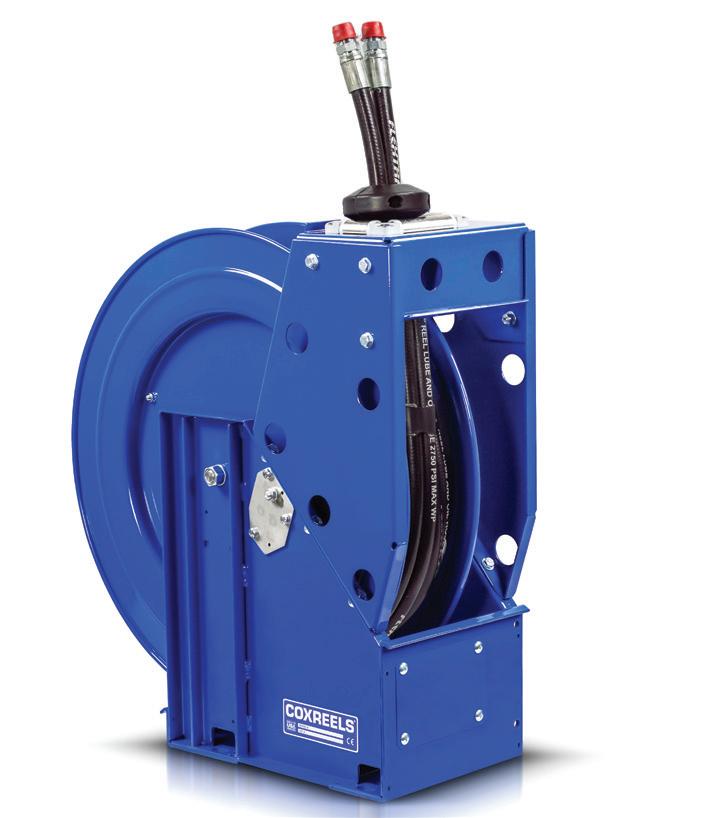
The multiplate system is a configurable coupling system that enables users to simultaneously connect and disconnect up to six hydraulic lines fitted with the company’s flat-face quickdisconnect couplings with a single movement — enabling faster assembly, maintenance, and attachment changeout. When configured to connect under pressure, the multiplate system supports easy manual connection up to 350 bar.
Compact and lightweight, the multiplate system reduces space requirements on machines. In addition, the system’s modular, flexible design enables customization to meet each machine’s specific requirements. Customers can specify coupling quantity (2 to 6), size (ISO size 6 to 19), style, and material. Electrical connectors and specialized couplings — such as water transfer, air transfer, and Danfoss snap-to-connect — can also be included.
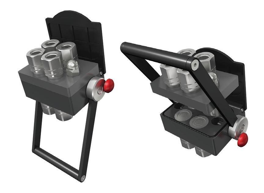
The DL Series Plug is specifically designed to permanently seal passages using the new Drive Locking technology. It is a single-piece, stainless-steel plug engineered to provide leak-tight performance in aluminum housings without the use of threads, sealants, or O-rings. This plug is suitable for highvolume applications where quality, performance, and reliability are critical to success. The DL Series Plug is rated for pressures up to 69 bar (1,000 psi) in aluminum manifolds and is designed to perform exceptionally well under adverse conditions. The plug is available in five standard body diameters: 4, 5, 6, 7, and 8 mm, and can seal passageways up to Ø 7.30 mm.
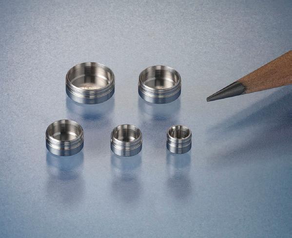
The Extreme Duty XTM Series spring rewind lineup — the Dual Hydraulic XTM-DMP-450 Reel — is for applications where dual hydraulic lines are required, such as in remote hydraulic equipment or accessories, including rescue tools, motors, and saws. Coxreels’ unique single-sided, dual-bodied hydraulic swivel allows both inlet connections to be on the same side of the reel. The withhose models include a twin-line fully bonded hose for smooth performance and handling. This XTM Dual Hydraulic Extreme Duty Reel is rated to 2,500 psi and made in the U.S. with a more impervious package than previously available.
Pop-lock hose catch hose whip
Hydraulic hose assemblies, whether on machinery or equipment, must be designed so that in the event of failure there is no danger from loose hoses acting like whips. With PopLock, UNIFLEX offers a safety device that meets the requirements of various standards and regulations. The Pop-Lock workshop “Hose retention system” is a safety system that offers a complete selection up to DN 50 (2 in.) in three sizes for all common nominal sizes: PopLock DN 05-12, DN 16-25, and DN 32-50. The workshop includes everything from wire rope cutters to safety gloves. Any rope length allows any hose protection.
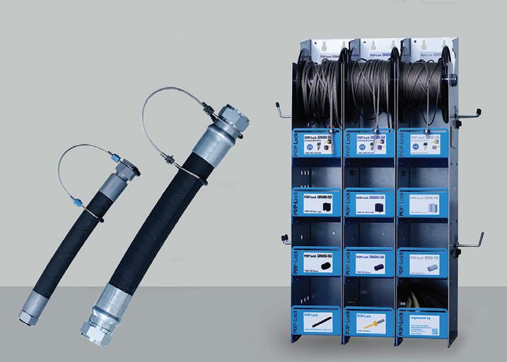
PRODUCT WORLD www.fluidpowerworld.com 4 • 2023 FLUID POWER WORLD 51
Multistage vacuum pumps
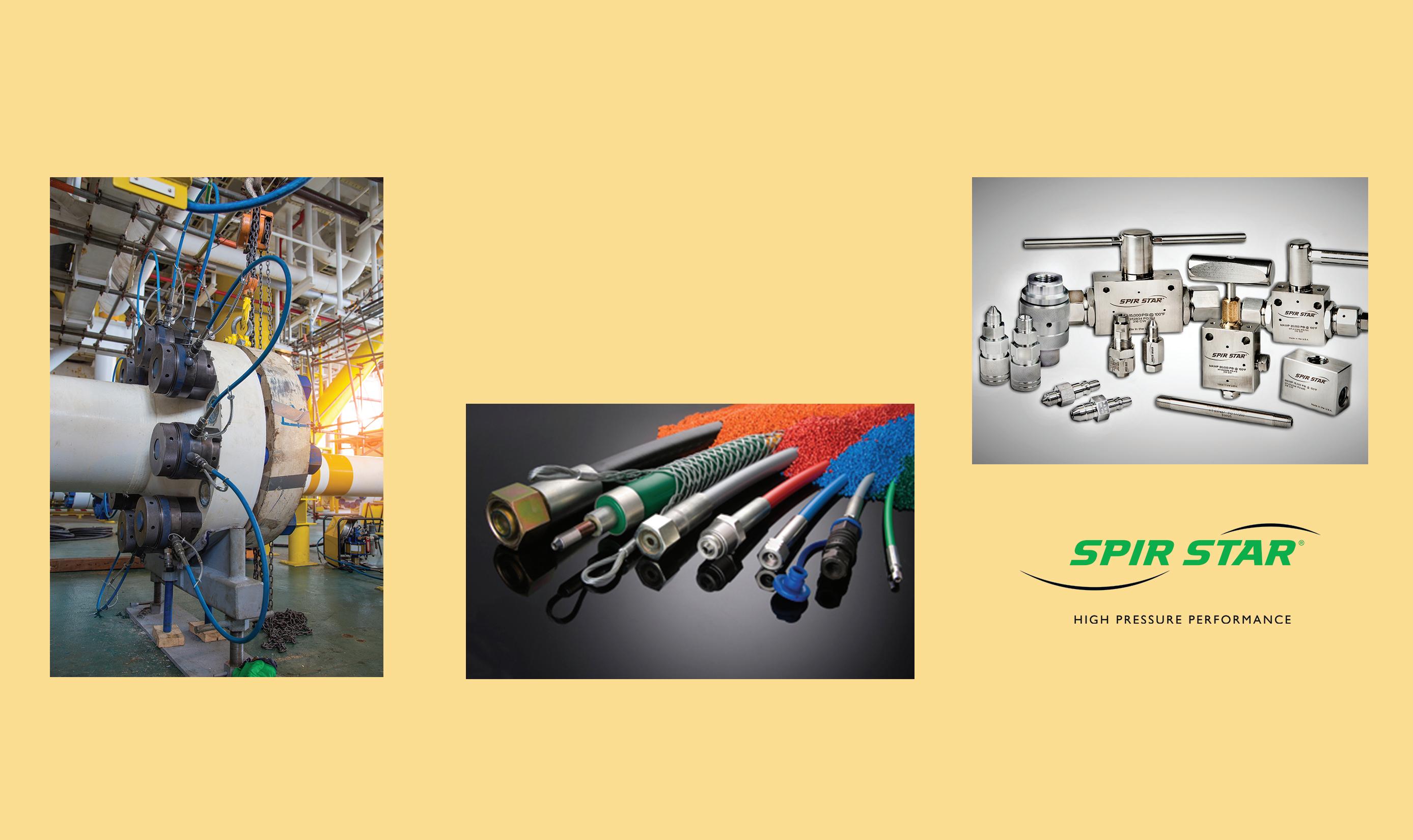
COVAL
www.coval-inc.com
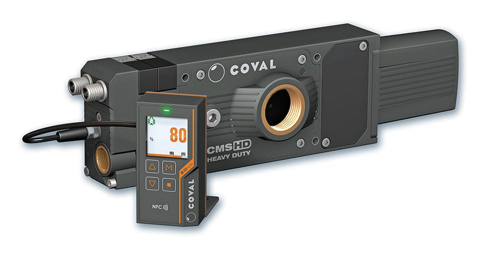
The VX range of vacuum pumps come with embedded intelligence. The multistage vacuum generation technology ensures that the CMS HD VX vacuum pumps have a high suction flow rate, up to 1600 Nl/min, as well as silent operation and reduced air consumption. They are particularly suitable for handling porous parts, such as cardboard boxes, or emptying large-volume tanks. The heavy-duty design offers high resistance and long service life even in the harsh environments (dust, oil, humidity) typical of production lines. The CMS HD VX pumps are extremely robust, with an IP65 protection rating and a service life of 50 million cycles. A contributing factor to their longevity is their modular design which allows specific configurations and targeted maintenance of specific parts to optimize the rate of repairability. The 1.54-in. color LCD display is intuitive, with clear messages in five languages.

PRODUCT WORLD
Overhung Load Adaptors
Single-valve dynamic pressure controls
Hydraulic hose sleeves
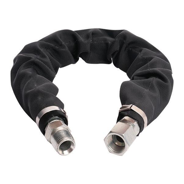
Zero-Max fills Overhung Load Adaptor void for discontinued products with its new 212k and 412k OHLA models for 2-bolt SAE A mount and 4-bolt non-SAE mount applications requiring a 1-1/4 in. output shaft. These two new OHLA designs feature robust ductile cast iron precision machined housings, deep groove ball bearings, enhanced sealing technology, strong shafts delivering long operating life, a permanent mounting surface, heavy load capacities, and high-speed ratings. Both models also feature precision gaskets for sealing the mounting surface between the hydraulic motor or pump and the OHLA housing. They also feature 1.000 in. input bore diameter with ¼ in. keyway and 1.250 in. output shaft diameter with ¼ in. keyway. Custom configurations are also available.
Cordis Pressure Controllers use the proven EVP and DVP proportional valve series allowing for steady, accurate, and repeatable downstream pressure control as demand or process changes. The result is a very precise linear pressure control within a closed-loop system providing ultra-high resolution and repeatability.
Features include:
• Smooth linear control
• Integrated internal feedback
• Multiple flow configurations
• Dynamic proportional pressure control
• Non-pulsing proportional fill
• Customizable pressure ranges
• Multiple inert gas compatible
• Customizable calibrated ranges
Load-sensing valves for mobile machinery
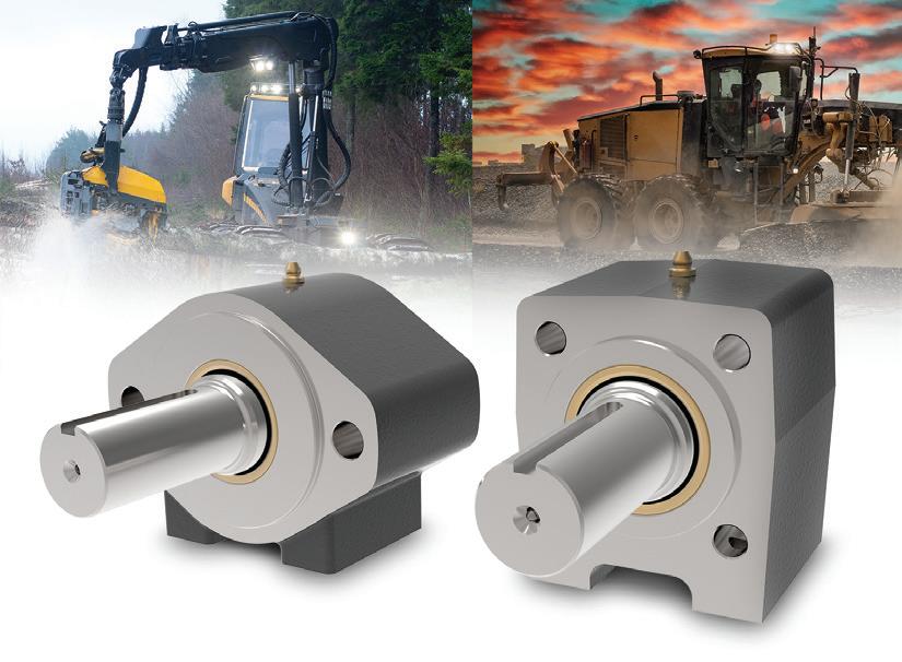
The VA Series is based on Parker’s existing high-end L90LS and K220LS valves that are known for robustness, controllability, and flexibility. With a maximum flow to workport of up to 450 lpm, the VA Series follows in the footsteps of the K220LS valve and takes the performance to the next level. The VA Series has been designed and optimized with features such as onboard electronics and readiness for Industry 4.0 or any other future demands regarding IoT and diagnostics. In addition to this, the new valve series also incorporates the latest hydraulic features — proportional counter pressure with active refill, warm-up possibilities, plus several other performanceenhancing improvements that herald the dawn of the next generation in mobile directional control valves.
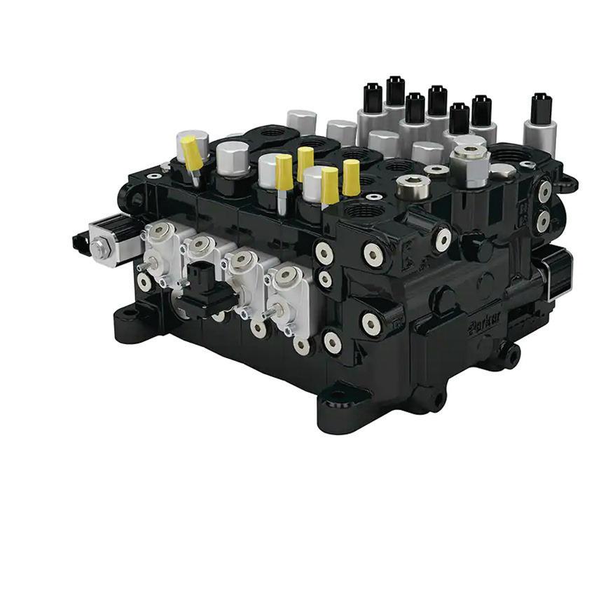
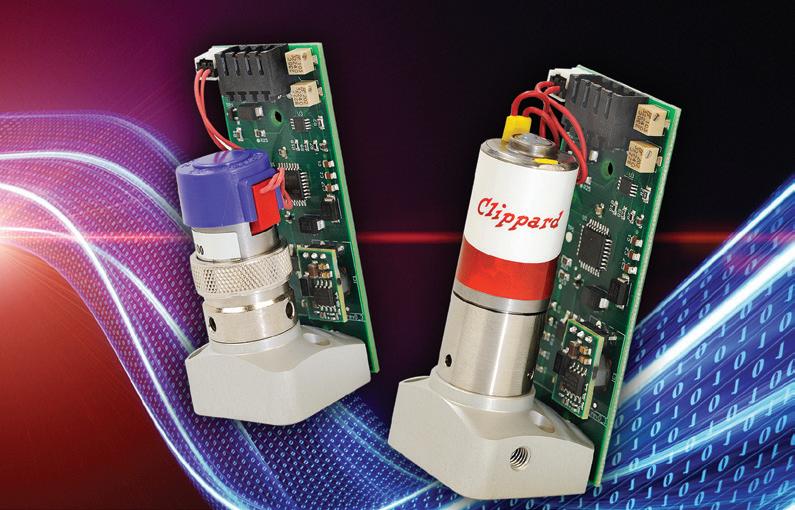
Diamondback Lite Sleeve is a tubular sleeve that joins Python’s other Diamondback Sleeves, Diamondback and Diamondback PRO. It is designed to provide UV protection and abrasion resistance to hydraulic hoses and wires. It is lightweight, flexible, and provides a clean, professional look to the application. The economical design features the exact amount of yarn needed to provide abrasion protection.
Key features and benefits include:
• Tested over 40,000 abrasion cycles (ISO 6945)
• Temperature tested to 200° F continuous, 350° F intermittent
• Easy install; cut to length with scissors
• Mine Safety and Health Administration (MSHA) approved
• Meets conductivity standard ISO 8031
• Unmatched UV protection
• Sleeve dispensers available
www.fluidpowerworld.com 4 • 2023 FLUID POWER WORLD 53


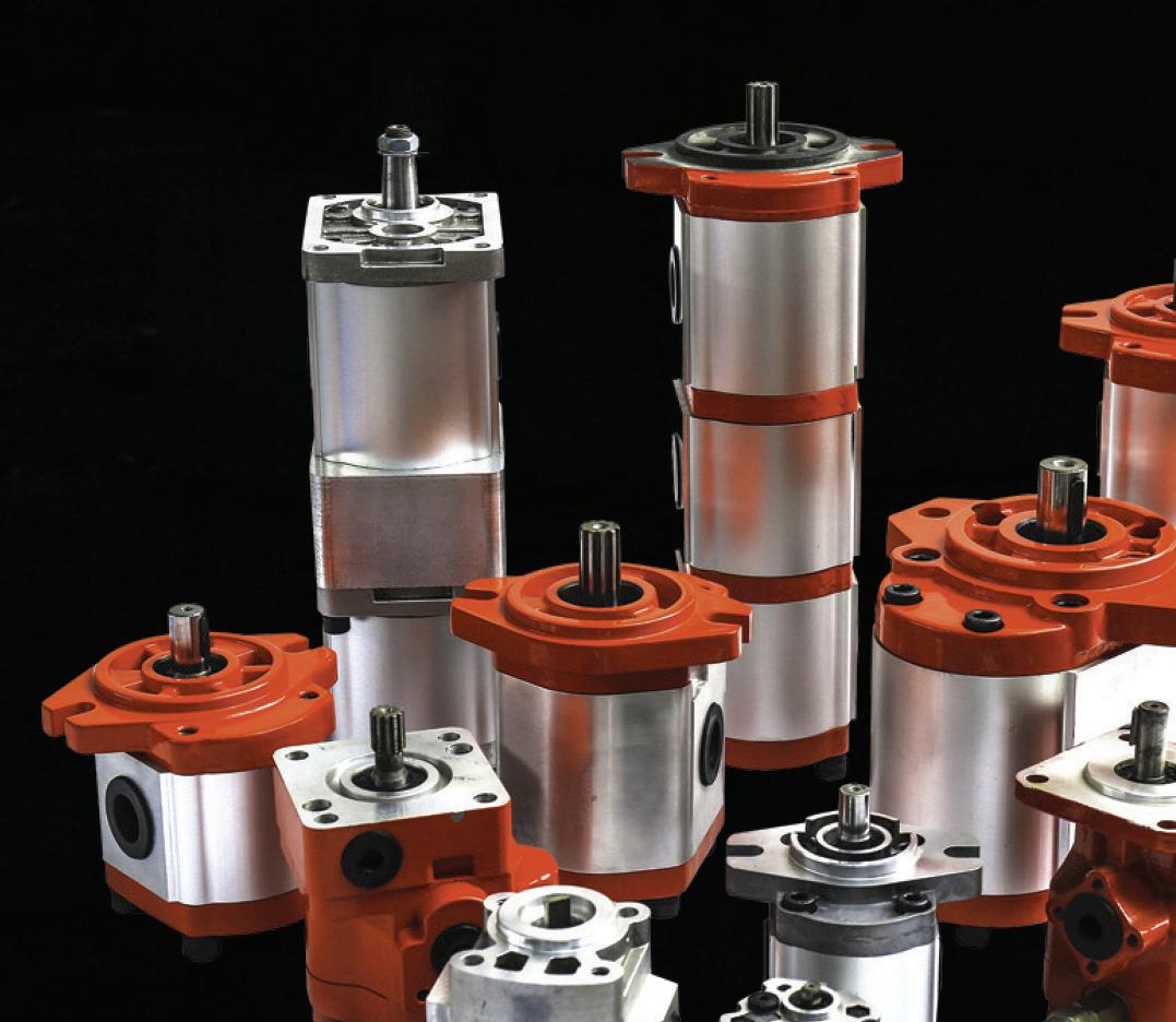


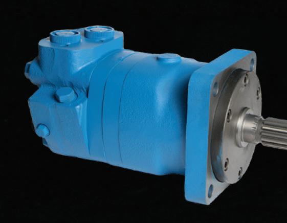

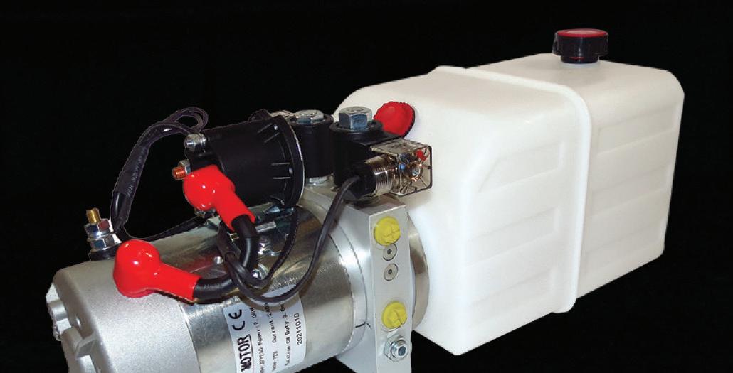
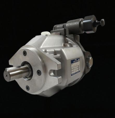
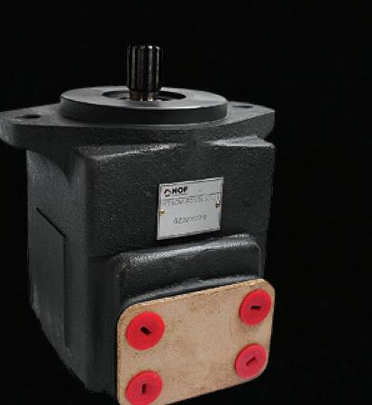


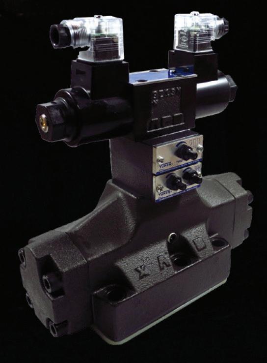

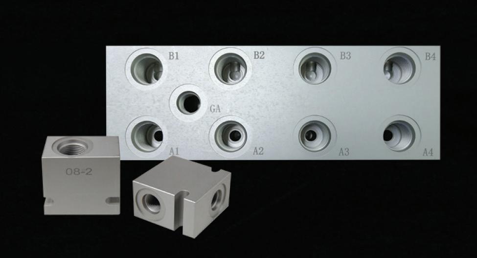
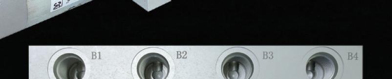
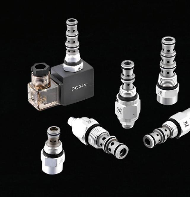
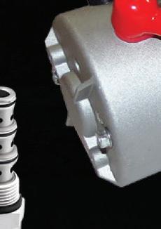
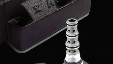


WE’RE YOUR SOURCE for Industrial and Mobile Fluid Power Solutions 3410 Delta Drive • Portage, IN 46368 • Tel: (219) 762-2059 • Fax: (219) 762-2066 • www.alaindustrieslimited.com ALA Industries Limited


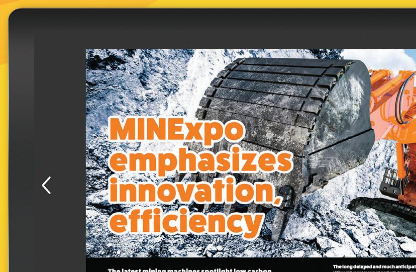
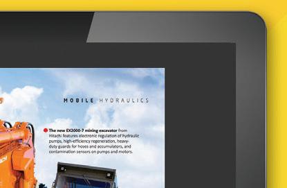


LEADERSHIP TEAM Co-Founder, VP Sales Mike Emich 508.446.1823 memich@wtwhmedia.com @wtwh_memic Co-Founder, Managing Partner Scott McCa erty 310.279.3844 smccafferty@wtwhmedia.com @SMMcCafferty EVP Marshall Matheson 805.895.3609 mmatheson@wtwhmedia.com @mmatheson Follow the whole team on twitter @FluidPowerWorld FOLLOW US ON ALA Industries ........................54 API Heat Transfer/Thermal 35 AutomationDirect ........ 1, Insert Brennan Industries BC DMIC 7 FluiDyne Fluid Power .............21 HOF 23 HydraForce .............................41 Main Mfg 8 MHA Zentgraf 15 MP Filtri USA ..........................13 Proportion Air .................. Cover Spir-Star 52 Stauff ........................................5 Super Swivel 49 Tampere University 9 Texcel .................................... IBC Tompkins Industries IFC, 8 Ultra Clean .............................39 Veljan Hydrair 27 Yuken 3 Zero-Max, Inc. ........................50 fluidpowerworld.com CHECK US OUT on ISSUU.COM! CONNECT WITH US! AD INDEX
Robert Sheaf • Founder/CEO of CFC Industrial Training

“Leak-proof” circuit experiencing drifting towards neutral
A vertical 20-in. bore cylinder press with a logic valve setup started drifting down in the neutral position. Unfortunately, many technicians are not familiar with the schematics of how logic valves work.
I always tell people that if they are piloted with a small directional valve then you should treat them like on-off valves. If there is pressure on the top, (spring side) they are held closed and if the top goes back to drain, they will open.
The maintenance technicians did know to remove the covers and check that all the orifices were open and if so, to pull the poppet out and examine it for problems. Of course, you must also make sure the cylinder piston is not causing the leak by blocking the cap end of the cylinder. A ball valve would work well to determine this; you then energize the circuit to retract the cylinder. If it slightly retracts and stops, the cylinder is fine. If it extends, then there is a piston leak causing the drift. Unfortunately, in this case, they replaced the cylinder thinking it must be the cause.
Can you identify what was the problem? We welcome responses of all kinds directly to Robert Sheaf at rjsheaf@cfc-solar.com or to mgannon@wtwhmedia.com. The solution will be provided in conjunction with our June 2023 issue. FPW
Solution to pressure problems on a multi-circuit system
In our December and April edition of Troubleshooting Challenge, we discussed a multi-circuit system at a zoo. The zoo enclosure problem was caused by the pilot-operated relief on the stand-by gas engine circuit. It had the control orifice partially blocked and relieved at a lower pressure than the cage doors required. The check valves were re-located after the stand-by filters on both systems to prevent this problem from happening again.
56 FLUID POWER WORLD 4 • 2023 www.fluidpowerworld.com
TROUBLESHOOTING CHALLENGE
TYPICAL CYLINDER CIRCUITS TO OTHER VALVES EM GAS SET @ 90 GPM SET @ SET @ NG40 16MM UNLOADING VALVE 50MM50MM 3:1 RATIO CYLINDER
One Fluid Solution For Your Hydraulic Needs.
We offer high-quality hydraulic hoses, fittings, and accessories with unmatched customer service to keep your business Ahead Of The Curve.
Your Partner For Over 40 Years
Rely on Texcel’s experienced and knowledgeable team for sales, technical support, customer service, and more.
Extensive & Premium Product Range
Our broad range of high-performing hydraulic hoses and fittings are designed to exceed your toughest applications.
Swift Service & Exceptional Inventory
Explore our U.S. hydraulic inventory, and buy everything you need on one Purchase Order with a 99.9% error-free rating.


TexcelHydraulics.com | 800.231.7116 | sales@TexcelRubber.com
Testing | Certification | Secure Online Portal | Technical Support | 24-Hour Response Team
Streamline Your Productivity With Premium Hydraulic Products & Services. SCAN TO GET STARTED
With 15 strategically located, full-service distribution centers across North America, Europe and Asia, our goal is to provide your fittings as fast as possible- when and where you need them.
70 years of MAKING CONNECTIONS
Brennan supplies customers worldwide with more than 120,000 standard and special hydraulic fittings, adapters and O-rings in sizes ranging from 1/16 to 3 inches. These include a wide choice of fitting and adapter types such as tube, O-ring face seal, instrumentation, metric bite type, push-to-connect, conversion and flareless bite type, as well as valves, clamps and swivels.
Brennan fittings are manufactured to the highest standards, meeting or exceeding J.I.C./S.A.E. and international specifications, with quality control certifications including DIN, ISO, ITAR, ASTM, NADCAP and AS9100.
brennaninc.com
