
the moon

PAGE 38
Hybrid hydraulics reduce emissions p. 30 From point A to B in material handling p. 35 Digital technologies transform pneumatics automation p. 44 www.fluidpowerworld.com October 2022

tompkinsind.com 800-255-1008ALWAYS ADAPTING. QUICK AND EASY.
ISO
Solenoid Valves Ready to Ship
Standard Pneumatic Solenoid Valves


(HVS-5211)
NITRA ISO 5599 valves are a robust directional air control solution that conforms to the ISO 5599/1 standard. They are sold as separate components, so you can buy what youneed to replace existing equipment or purchase all the components needed to build a new system.


ISO 5599/1 sizes 1 and 2 are interchangeable with all other brands meeting the ISO 5599/1 specification


5-port / 2-position and 5-port / 3-position

Solenoid coils sold separately in 12 & 24 VDC and 24, 110 & 220


Order stand-alone
Bases and
or


are available in either G-thread (BSPP) or


the #1 value in automation Order Today, Ships Fast! * See our Web site for details and restrictions. © Copyright 2022 AutomationDirect, Cumming, GA USA. All rights reserved. 1-800-633-0405
•
•
valves available •
VAC •
bases
manifolds separately •
manifolds
NPT
5599
Also Available ISO 5599/1
Starting at $86.00
ISO 5599/1 SOLENOID VALVES STARTING AT $86.00 (HVS-5211) Air prep, cylinders, fittings and more…Air Pilot Valves Manual Valves Research, price, buy at: www.automationdirect.com/pneumatics
Welcoming our newest editorial member
Last month, we were thrilled to welcome a new staff member to Fluid Power World —
Rachael Pasini. As senior editor, she will be writing and editing much of the content you will read each day on our websites and in our monthly print issues. Rachael will be managing several print departments, particularly our Design Notes section, fundamentals, and more.
Rachael will also be writing and editing at least one of our technical features in each print issue. Turn to page 30 for her first byline, as she delves into how hydraulic hybrid technology from Parker Hannifin is helping to reduce emissions and enable efficiency in waste management vehicles.

Additionally, as our editorial team refocuses our Fluid Power Technology Conference, look to see her more involved, moderating discussions and panels at the event next year.

Rachael will also be taking the lead as we work to develop more unique content for our audience. There, you’ll see more submitted technical articles from experts in the industry as we work to educate you, our readers, on the technologies you use every day in your system and machine designs.
Rachael is well-qualified as a technical writer and is eager to learn more about fluid power technologies. Here’s a look at some highlights of her technical career:
• Master’s degree in civil and environmental engineering and bachelor’s degree in industrial and systems engineering from The Ohio State University


• Over 15 years of experience as a technical writer in engineering and information technology


• Taught college math and physics
We are delighted to welcome Rachael to our team. Her expertise will ensure we continue to fulfill our mission at Fluid Power World — providing the best hydraulic and pneumatic technical content, written and presented by engineers for engineers.

I urge you to follow Rachael on Twitter at @WTWH_Rachael, on LinkedIn, and of course, contact her at rpasini@wtwhmedia.com. FPW
Mary C. Gannon • Editor-in -Chief mgannon@wtwhmedia.com
On Twitter @FPW_marygannon
 Mary C. Gannon • Editor-in-Chief
FLUIDLINES
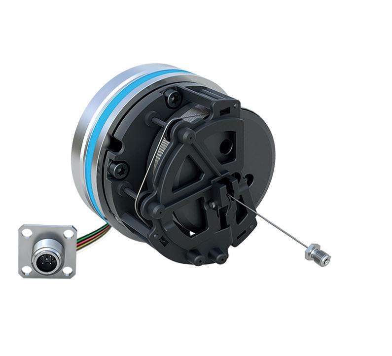
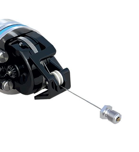
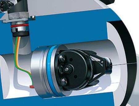
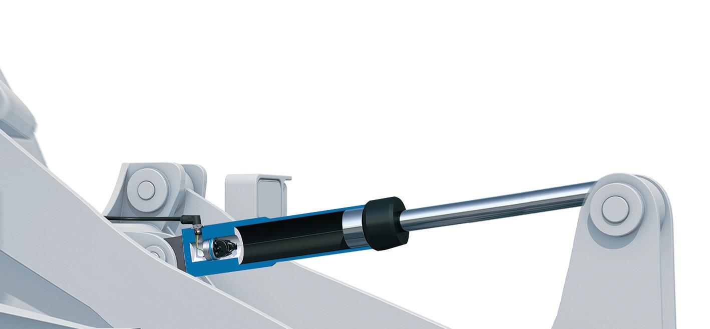
POSITION SENSORS FOR HYDRAULIC CYLINDERS Absolute detection of the cylinder stroke No piston drilling necessary Can also be used in telescopic cylinders High shock and vibration resistance, IP69K SIKO Products Inc., www.siko-global.com BAUMA 2022, Hall A2, Booth 415
Rachael Pasini, Senior Editor
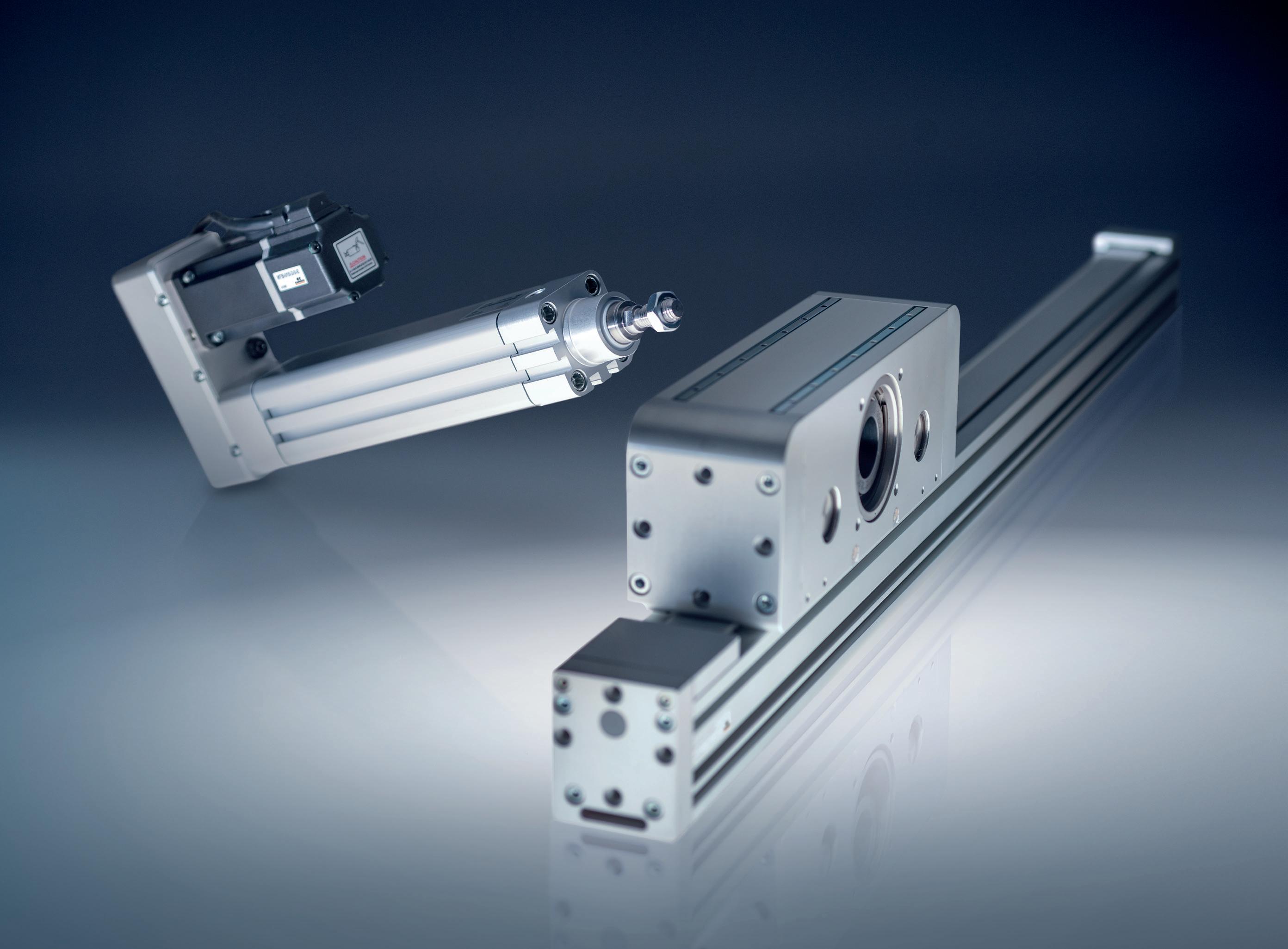
ELECTRIC ACTUATION
APPLICATIONS
THE ULTIMATE IN FLEXIBILITY AND EFFICIENCY
Multi-axis solutions are made easier with Camozzi’s range of modular electric actuators. Ready-made motor and mounting transition plates may be combined with various transmission technologies to satisfy the most demanding design challenges.
PACKAGING
FOOD & BEVERAGE
& ROBOTICS
SYSTEMS
·
ASSEMBLY
· AUTOMOTIVE · ELECTRONIC
TRANSPORTATIONFOR MORE INFORMATION · TINYURL.COM/CAMOZZI-ELEC-ACTUATION
FROM THE FIELD
Paul J. Heney • VP, Editorial Director
Robots, cobots, pneumatics, and the future
At the National Fluid Power Association’s recent International Economic Outlook Conference, Donna Ritson of DDR

Communications shared results of an industry survey done for PMMI that looks at the future of robots and cobots for automation.
Ritson’s firm had discussions with the leading robot manufacturers, robot suppliers, and integrators in the industry to get their perspectives on the role of pneumatics in robots and cobots. The survey included industries such as food, beverage, personal care, pharma, medical devices, household products, and agriculture.
“We really covered the gamut because they’re all using robots and cobots,” she said. “We talked to large companies — those are your leaders, your early adopters — as well as medium-sized and smaller companies. Everyone is looking at this, with the number one reason being lack of labor. That’s not old news, it’s continuing news.”
Ritson said that the main challenge for integrating robots and cobots lies in the questions of:
• Where do I put them?
• Where can I improve my productivity?
• Where can we add the best efficiency?
Companies are really looking for application identification. When they’re going to add a robot or cobot, they’re clearly expecting things to improve. Users almost unanimously want to cut back on repetitive tasks to reduce labor, increase speed and productivity, achieve more throughput, maintain higher levels of quality, achieve consistent handling, and improve operator safety.
“If you can have a robot do a hazardous job, then that will improve your worker safety as well,” Ritson said. “And minimize waste and human error. Robots can be

programmed to do the same thing over and over — far better than humans.”
Pneumatics gets in the game Robot experts listed the benefits of pneumatics on end of arm tooling as being cost effective, easier to use, simpler to troubleshoot, lightweight, and powerful.
“Pneumatics are a key component in robotic end effectors, and not necessarily just for the typical applications of gripping or holding something or moving something,” she said. “They are also being used as a driving tool, a welding tool, a boring tool — things that aren’t your typical lift, move, handle applications.”
Ritson identified some hurdles for companies adopting more automation than they already have as being a lack of engineers on staff, not enough floor space, not having the technology to do proper
troubleshooting, or simply not having the right application.
With pneumatics specifically, there’s also the question of the availability of compressed air in the facility. Robots may be placed in a part of a facility where the air isn’t available. And some companies’ engineering staffs may have more familiarity with electrics than pneumatics, so education becomes critical.
It’s important to remember that application complexity and accuracy are what’s driving the actuation choice between pneumatics versus a servo electric solution. Robotics experts told Ritson that the benefits of pneumatics are simple: sequential operations, pick-and-place applications, and safe operating modes.
“If it’s simple pick and place, then it’s a good fit for pneumatics,” Ritson explained.


“For motor and electric applications, there’s

4 FLUID POWER WORLD 10 • 2022 www.fluidpowerworld.com
Donna Ritson, DDR Communications, highlights how pneumatics can enable better robots and cobots at the NFPA IEOC in August 2022.
energy savings that they’re looking for. If it’s got a sophisticated motion path, it’s teachable or guidable, these are all applications where they’re selecting the electric option.”


“The questions to ask your customers are, ‘Is the task repetitive? What kind of application? Does it require high accuracy? What type of an environment is it in? What operator level is in your plant now? Where are you starting at, from a level of knowledge? And what other areas of operation is this going to impact in the future?’” she said.
Other factors
Ritson mentioned that COVID is still driving a lot of decisions and changes in manufacturing.
“In general, it’s driving more automation. In an independent study we conducted, about a third of the people participating had already implemented robots and cobots in new technology,” she said.

Robot experts are also looking for functional improvements that are needed for the greater adoption of pneumatics in robots and cobots, such as the ability to move heavier objects and more seamless integration of the pneumatic controls.

“We’re talking about less programming and more teachable operations, and integration of those pneumatic controls into the cobot, the regulators and the valves, the feedback loops to achieve a more plug and play compatibility,” she said. “And plug and play is something that we definitely hear about; it is desirable because that decreases the need for programming. The industry is looking for a broader range of solutions from pneumatics and cobots and robots.”
From a spending perspective, Ritson’s data shows that more than half of the companies surveyed are planning to spend more in the next decade on robots, cobots, and automation than they had in the past 10 years. The spending level is increasing — they know they need this type of automation, as labor will remain difficult to find.
“Companies are expecting their suppliers to provide a solid business case,” she said. “They’re saying, ‘Give us the reasons why robots and cobots will help us improve our operations.’ You may have to conduct a plant audit, go into their facilities, and help them find the applications that they need to improve. Where is labor lacking and how can automation be part of that?”
Paul J. Heney VP, Editorial Director pheney@wtwhmedia.com


 On Twitter @wtwh_paulheney


10 • 2022 FLUID POWER WORLD 5
FPW
WASTE MANAGEMENT

MOBILE HYDRAULICS


HYDRAULIC CYLINDERS

PNEUMATICS
6 FLUID POWER WORLD 10 • 2022 30 38 44 35 OCTOBER 2022 FEATURES
Electric-hydraulic hybrid systems reduce emissions in refuse collection vehicles Hybrid systems bridge the road to electrification with small batteries and readily available components.
Moving from point A to B with hydraulics Mobile material handling machines rely heavily on hydraulic technologies which pair well with the robust, sometimes challenging environments these machines work in.
Hydraulic cylinders keep moon rocket on track Jacking and equalizing cylinders on NASA’s crawler transporter hold steady the massive launch vehicle.
Analytics power: Optimizing operations through digital transformation Digital technologies along with pneumatics automation can transform a facility’s efficiency, productivity, and versatility. Contents | vol 9 no 6 | fluidpowerworld.com • 10 • 2022 ON THE COVER Jacking and equalizing cylinders on NASA’s crawler transporter, hold steady the massive launch vehicle used to carry the Artemis I rocket and spacecraft from the assembly building to the launch pads. | Courtesy of NASA asbpe.org SILVER NATIONAL AWARD asbpe.org SILVER REGIONAL AWARD DEPARTMENTS 02 FluidLines 04 From The Field 10 Korane’s Outlook 12 Troubleshooting Challenge 14 Association Watch 16 Design Notes 24 Fundamentals 26 Maintenance 28 Energy Efficiency 50 Products 55 Component Focus 56 Ad Index
SUMMIT


REACHING PEAK PERFORMANCE


ENLIGHTENING SPEAKERS › EXCEPTIONAL NETWORKING


For more information about this one-of-a-kind distribution industry event, visit

INDUSTRY
INDUSTRY-SUMMIT.ORG
EDITORIAL
VP, Editorial Director Paul J. Heney pheney@wtwhmedia.com @wtwh_paulheney

Editor-in-Chief Mary Gannon mgannon@wtwhmedia.com @dw_marygannon
Technology Editor Ken Korane kkorane@wtwhmedia.com @fpw_kenkorane
Senior Editor Rachael Pasini rpasini@wtwhmedia.com
Associate Editor Heather Hall hhall@wtwhmedia.com @wtwh_heathhall

Contributing Editor Josh Cosford @FluidPowerTips


Contributing Editor Carl Dyke @carlindustry
BSPT,
Contributing Writer Robert Sheaf rjsheaf@cfc-solar.com
PRINT PRODUCTION
VP, Creative Services Mark Rook mrook@wtwhmedia.com @wtwh_graphics
Senior Art Director Matthew Claney mclaney@wtwhmedia.com @wtwh_designer
Senior Graphic Designer Allison Washko awashko@wtwhmedia.com @wtwh_allison
Graphic Designer Mariel Evans mevans@wtwhmedia.com @wtwh_mariel
Director, Audience Development Bruce Sprague bsprague@wtwhmedia.com
MARKETING
VP, Digital Marketing Virginia Goulding vgoulding@wtwhmedia.com @wtwh_virginia
Digital Marketing Manager Taylor Meade tmeade@wtwhmedia.com @wtwh_taylor
Digital Production/ Marketing Designer Samantha King sking@wtwhmedia.com Marketing Graphic Designer Hannah Bragg hbragg@wtwhmedia.com
Webinar Manager Matt Boblett mboblett@wtwhmedia.com
Webinar Coordinator Halle Kirsh hkirsh@wtwhmedia.com
Webinar Coordinator Kim Dorsey kdorsey@wtwhmedia.com
PRODUCTION SERVICES

Customer Service Manager Stephanie Hulett shulett@wtwhmedia.com
Customer Service Representative Tracy Powers tpowers@wtwhmedia.com
Customer Service
Representative JoAnn Martin jmartin@wtwhmedia.com

Customer Service
Representative Renee Massey-Linston renee@wtwhmedia.com
Customer Service
Representative Trinidy Longgood tlonggood@wtwhmedia.com
IN-PERSON EVENTS
Events Manager Jen Osborne jkolasky@wtwhmedia.com @wtwh_jen
Events Manager Brittany Belko bbelko@wtwhmedia.com
Event Marketing Specialist Olivia Zemanek ozemanek@wtwhmedia.com
FINANCE Controller Brian Korsberg bkorsberg@wtwhmedia.com
Accounts Receivable Specialist Jamila Milton jmilton@wtwhmedia.com

Specialist Nicole Lender nlender@wtwhmedia.com
Digital Production Specialist Elise Ondak eondak@wtwhmedia.com
Digital Production Specialist Nicole Johnson njohnson@wtwhmedia.com
VP, Strategic Initiatives Jay Hopper jhopper@wtwhmedia.com


www.nfpa.com OCTOBER 2022 • vol 9 no 6 • www.fluidpowerworld.com VIDEO SERVICES Video Manager Bradley Voyten bvoyten@wtwhmedia.com @bv10wtwh Videographer Garrett McCa erty gmccafferty@wtwhmedia.com Videographer Kara Singleton ksingleton@wtwhmedia.com SALES Ryan Ashdown 216-316-6691 rashdown@wtwhmedia.com Jami Brownlee 224.760.1055 jbrownlee@wtwhmedia.com Mary Ann Cooke 781.710.4659 mcooke@wtwhmedia.com Jim Powers 312.925.7793 jpowers@wtwhmedia.com @jpowers_media Courtney Nagle 440.523.1685 cseel@wtwhmedia.com @wtwh_CSeel ONLINE DEVELOPMENT & PRODUCTION Web Development Manager B. David Miyares dmiyares@wtwhmedia.com @wtwh_webdave Senior Digital Media Manager Patrick Curran pcurran@wtwhmedia.com @wtwhseopatrick Front End Developer Melissa Annand mannand@wtwhmedia.com Software Engineer David Bozentka dbozentka@wtwhmedia.com Digital Production Manager Reggie Hall rhall@wtwhmedia.com Digital Production
Don’t compromise! Use MAIN Manufacturing Products, Inc. as your source for hydraulic flanges Dependable - 60 yrs service Informed - members of SAE & NFPA tech committees Quick - Thousands in stock specials can be 3-4 days MAIN Manufacturing Products, Inc. Grand Blanc, MI USA 800.521.7918 Info@MainMfg.com MAINMfg.com SAE 4-bolt, JIS, DIN, ISO standard & special adapters Socket and Butt weld, NPTF
ORB, BSPP, 6149, etc. Materials: Carbon, 304L, 316L, duplex, Cu-NI, ductile, alum. etc. In-line, el, tee, F, blind, cross, reducing, flange heads Made in USA tompkinsind.com 800-255-1008ALWAYS ADAPTING. QUICK AND EASY. 8 FLUID POWER WORLD 10 • 2022 2011- 2020 FLUID POWER WORLD does not pass judgment on subjects of controversy nor enter into dispute with or between any individuals or organizations. FLUID POWER WORLD is also an independent forum for the expression of opinions relevant to industry issues. Letters to the editor and by-lined articles express the views of the author and not necessarily of the publisher or the publication. Every effort is made to provide accurate information; however, publisher assumes no responsibility for accuracy of submitted advertising and editorial information. Noncommissioned articles and news releases cannot be acknowledged. Unsolicited materials cannot be returned nor will this organization assume responsibility for their care. FLUID POWER WORLD does not endorse any products, programs or services of advertisers or editorial contributors. Copyright© 2022 by WTWH Media, LLC. No part of this publication may be reproduced in any form or by any means, electronic or mechanical, or by recording, or by any information storage or retrieval system, without written permission from the publisher. SUBSCRIPTION RATES: Free and controlled circulation to qualified subscribers. Non-qualified persons may subscribe at the following rates: U.S. and possessions: 1 year: $125; 2 years: $200; 3 years: $275; Canadian and foreign, 1 year: $195; only US funds are accepted. Single copies $15 each. Subscriptions are prepaid, and check or money orders only. SUBSCRIBER SERVICES: To order a subscription please visit our web site at www.fluidpowerworld.com FLUID POWER WORLD (ISSN 2375-3641) is published seven times a year: in February, April, June, July, August, October, and December by WTWH Media, LLC; 1111 Superior Ave., Suite 2600, Cleveland, Ohio 44114. Periodicals postage paid at Cleveland, OH & additional mailing offices. POSTMASTER: Send address changes to: Fluid Power World, 1111 Superior Ave., Suite 2600, Cleveland, OH 44114 2013- 20172014- 2016 2014 Winner WTWH Media, LLC 1111 Superior Ave., Suite 2600, Cleveland, OH 44114 Ph: 888.543.2447 • Fax: 888.543.2447
 KORANE’S OUTLOOK Ken Korane • Technology Editor

Finally, a win for domestic manufacturing
There is no problem, goes the current wisdom, which some federal program won’t try to solve by throwing money at it. That is, unless it means devoting dollars for research on traditional manufacturing processes.
Take, for instance, the National Science Foundation, a government entity that supports fundamental research and education in all the non-medical fields of science and engineering. It has an $8.8 billion budget and awards hundreds of millions of dollars annually in so-called “next-generation” projects — this year $900 million for climate change and clean energy technology, $636 million on artificial intelligence research, $435 million on nanotechnology and $220 million on quantum information science. It will even spend $50 million for new STEM workforce diversity initiatives.
But when it comes to funding research for more-conventional operations like forging and casting, support is harder to come by. Meanwhile, countries like China and Germany spend generously on manufacturing R&D, labs and researchers because they understand investments that advance manufacturing technology ultimately strengthens their economies, fosters growth and maintains their standing as export powerhouses.
That’s why the NSF’s recent announcement of up to $52 million in funding for a new Engineering Research Center is a big deal. Dedicated to developing and commercializing advanced, intelligent production systems, the Hybrid Autonomous Manufacturing, Moving from Evolution to Revolution (HAMMER) ERC — of which fluid power promises to be a key contributor — will help grow a next-generation American manufacturing industry and ease national security and supply chain issues, according to the NSF.
HAMMER’s primary goal is to create hybrid manufacturing systems such as for metamorphic manufacturing. MM is essentially autonomous open-die forging where servohydraulic-driven tools repeatedly and incrementally form a piece of metal that is precisely positioned by a robot. It is seen as a cost-effective way to craft
intricate parts with specific engineering properties and locally defined microstructures based on well-understood metal-processing methods, and is suitable for rapid customization of everything from small medical implants to extremely large structural components.
Proponents say compared to CNC machining and additive manufacturing, MM is faster and produces parts with higher strength and toughness, with less waste and requiring less energy. And it could lower the economic barriers many small- and medium-sized manufacturers face and help expand domestic production capacity.
On the development curve MM is just in its infancy, akin to CNC machining in the 1940s. But it is building upon a well-established knowledge base encompassing sensors, heat-treating methods, hydraulic actuators, robots and high-speed processors. Experts say that given adequate funding, there is no reason these various elements cannot be quickly melded together as a useful and practical manufacturing technology. After all, the idea of integrating robots and tools with sensors and software, the essence of IoT, is increasingly being embraced across the industrial landscape.
The Defense Department is paying attention, too. It views forgings and castings as one of the most critical vulnerabilities to national security. Forged and cast components are essential in everything from ships and subs to aircraft, combat vehicles and weapons systems. But due to offshoring and industry consolidation there are relatively few domestic suppliers of many mission-critical components. Thus, DoD counts on foreign countries, including China, for very large cast and forged products found in some defense systems. They’re also essential components that go into many of the machine tools and presses used to make such parts.
Industry and government leaders alike view as a major problem the fact that the U.S. has ceded much of its manufacturing base to China. It puts us in a precarious position vulnerable to supply chain disruptions and security threats. Producing critical goods domestically, which HAMMER envisions, would go a long way toward creating a more-vibrant domestic industrial capacity to bolster national defense and ensure long-term economic competitiveness. FPW
10 FLUID POWER WORLD 10 • 2022 www.fluidpowerworld.com
|
Courtesy
of Adobe Stock
 Robert Sheaf • Founder/CEO of CFC Industrial Training

System overheating on drum pusher system
A scrap processing company has a large rotating drum that pushes scrap aluminum components into rotating hammers to pulverize the scrap parts into small pieces. They then press the scrap into large bales for easy shipping.
The attached circuit is one of the hydraulic systems that runs three functions on the machine. They had problems with one system overheating. They assumed that one of the cylinders was by-passing, so they replaced both cylinders. Then they decided to replace the counterbalance valve.
Throughout all of this, they were troubleshooting without a circuit. They did find one after the service man they called in insisted he needed it to troubleshoot the system.
What do you think he found the problem to be?
Solution to System could only build pressure on one end of cylinder
If the external signal to the load sense control is vented to tank, the pump will compensate at the low load sense pressure of 300 psi. The ball inside the shuttle had been driven and jammed in the incoming signal side of the shuttle going to the rod side.
They replaced the shuttle and installed small orifices in both lines going into the shuttle to soften the shifting speed of the ball in the shuttle.
12 FLUID POWER WORLD 10 • 2022 www.fluidpowerworld.com
TROUBLESHOOTING CHALLENGE
FPW Circuit 7 EM Gage A Sol. 1A Sol. 1B 3000 PSI Set Max Compensator to 2700 PSI Set Load Sense to 300 PSI Gage CGage B EM P I P I P I SOL. 1B SOL. 2A SOL. 3A SOL. 3B SOL. 4A SOL. 4B UNLOADER 4 - BANK MANIFOLD LOCATED UNDER MAIN FRAME DOOR LOCKS CONVEYOR PUSHER
FPW


What are your machine challenges? You’ll find the answers with HydraForce – the world leader in precision hydraulic motion controls for mobile and industrial applications. Partnering with HydraForce, you’ll have access to unmatched engineering expertise; the industry’s broadest range of cartridge valves; custom integrated-circuit manifolds, and best-in-class remote-management solutions. Now you have the power to build a better machine. Visit HydraForce.com HydraForce.com. © 2022 HydraForce, Inc. LINCOLNSHIRE, IL, USA 847-793-2300 BIRMINGHAM, UK 44 121 333 1800 CHANGZHOU, CHINA 86 519 6988 1200 SÃO PAULO, BRAZ IL 55 11 4786 4555 THE HARDEST WORKING MACHINES HYDRAFORCE. RELY ON Munich, Germany Hall A4 / Booth 450
Edited by Mary C. Gannon • Editor-in-Chief

IFPS promotes Donna Pollander to CEO
During its 2022 annual meeting, the International Fluid Power Society (IFPS) Board of Directors announced Donna Pollander as the organization’s Chief Executive Officer. In this role, Ms. Pollander will continue to serve as key liaison to the Board of Directors, responsible for the organization’s day-today operations ensuring the consistent achievement of IFPS’ mission and financial objectives. She will continue to provide leadership in developing Certification Programs as well as other educational programs relating to fluid power training, organizational and financial plans with the Board of Directors and staff.
“Donna was, in reality, performing the duties as CEO for quite a while, so the Board felt it was time to acknowledge her efforts,” said Denis Poirier, IFPS 2022 President.
Donna started her career in fluid power in 1995, working part-time with an association management company who managed the Fluid Power Distributor’s association. She’s held various full- and part-time positions within the association management company, until her promotion to IFPS’ Executive Director in 2003. IFPS decided to hire the staff in 2014. Quoting Ms. Pollander “The IFPS is part of the fiber of who I am, and I am proud to see it flourishing. IFPS’ future is bright, and I am very excited to be at the helm of such an integral part of the fluid power industry!”


The IFPS is a nonprofit 501(c)(3) professional organization of individuals dedicated to enhancing the quality of certifications, educational opportunities, technology evolution, and professionalism within the fluid power and motion control industry. The IFPS was started in Detroit in 1960 by a group of 30 professionals interested in supporting the future of the fluid power industry and the ever-changing technologies involved. Beginning with the first Fluid Power Hydraulic Specialist Certification in 1980, the IFPS has become the recognized industry leader in fluid power and motion control certifications. Fifteen different certifications are currently offered with two certifications in development. These certifications cover diverse job descriptions within the industry including mechanic, technician, specialist, system designer, and engineer. To date over 34,000 certifications have been issued. FPW
IFPS launches second edition of Fluid Power Reference Handbook

The International Fluid Power Society recently published the second edition of its Fluid Power Reference Handbook, which contains both U.S. customary and metric units, fullcolor graphics, charts, drawings, and symbology that comply with ISO, ANSI, and SAE standards.

The book is available as either soft or hard cover and offers nearly 400 pages of topics covering safety, symbology, fluid power data, fluids, fluid conditioning, connectors and conductors, reservoirs, compressors, prime movers, valves, cylinders, motors, semi-rotary actuators, vacuum, accumulators, control theory, troubleshooting algorithms, pumps, and a glossary of terms. The new edition features 28 additional pages of content, including:
• Expanded symbology section (which include ISO compliant symbols)
• New and enhanced graphics


• Expanded topics
• Updated charts (ISO, ANSI and SAE compliant)
The Handbook is available for $74.95 for members and $125.95 for non-members. Discounts are available for more than 10 books. Visit ifps.org for more details.
IFPS | Ifps.org 14 FLUID POWER WORLD 10 • 2022 www.fluidpowerworld.com
ASSOCIATION WATCH
Donna Pollander, CEO of IFPS
FPW
NFPA Education and Technology Foundation to administer Thomas Wanke Legacy Fund

Thomas Wanke was a monumental figure in fluid power, active for more than 50 years and influencing generations of fluid power engineers through his work at the Milwaukee School of Engineering, its Fluid Power Institute, and with the National Fluid Power Association. To honor his memory, and to help ensure that his positive impact on fluid power education continues to be felt, the NFPA Education and Technology Foundation has been asked to administer the Thomas Wanke Legacy Fund, a dedicated funding mechanism that will support fluid power scholarships and education activities at universities throughout the United States.
In the wake of Wanke’s passing, his widow, Ann, set-up a temporary structure to collect donations in his name. His many friends, former students, and colleagues responded, with more than $10,000 donated so far. With a transfer of those donations to the NFPA Education and Technology Foundation, a 501(c)(3) tax-exempt charitable organization, those donations can now be recognized as fully tax deductible. Additional donations can be made directly to the NFPA Foundation, and NFPA will be matching all donations received, up to a maximum of $25,000, to help establish and provide essential base funding for this new Legacy Fund.


To make your contribution, visit nfpafoundation.org.


Through a series of annual awards from this fund, the NFPA Foundation will be able to increase both the number of students studying fluid power, and also the quality of fluid power education in our nation’s universities — two goals clearly aligned with and ennobled by Wanke’s life and legacy.

Please contact NFPA President and CEO, Eric Lanke, at elanke@nfpa.com or (414) 778-3351 with any questions.


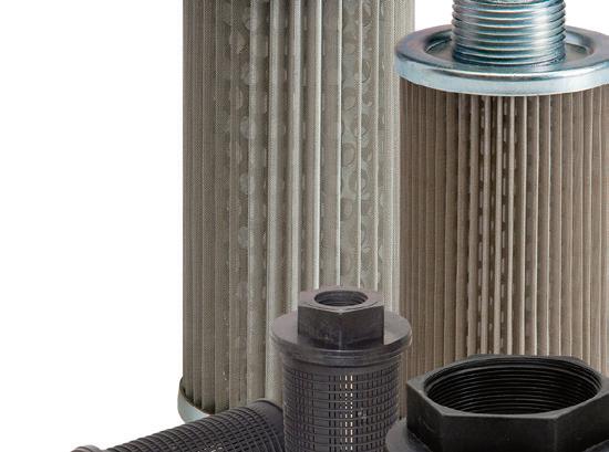
WHERE ARE YOUR FILTERS? If you bought from OFCO, you’d be using them now. Strainers • Filters • Breathers • Diffusers Stock and Custom Filtration Solutions Ohio Fabricators Company designs and manufactures your hydraulic solutions right here in our Central Ohio factory. Our quick-ship program for standard products means you receive your shipment within days, not months. Even customfiltration solutions get our unparalleled delivery times. info@ohfab.com • 888.354.0291 www.ohfab.com Call or email our sales team today to check our stock and discuss your specifications.Proudly Made in the USA • ISO 9001:2015 Compliant NFPA Education and Technology Foundation to administer Thomas Wanke Legacy Fund to support fluid power education.
DESIGN NOTES


 Edited by Rachael Pasini • Senior Editor


Pneumatic system upgrade preserves

collegiate tradition
16 FLUID POWER WORLD 10 • 2022 www.fluidpowerworld.com
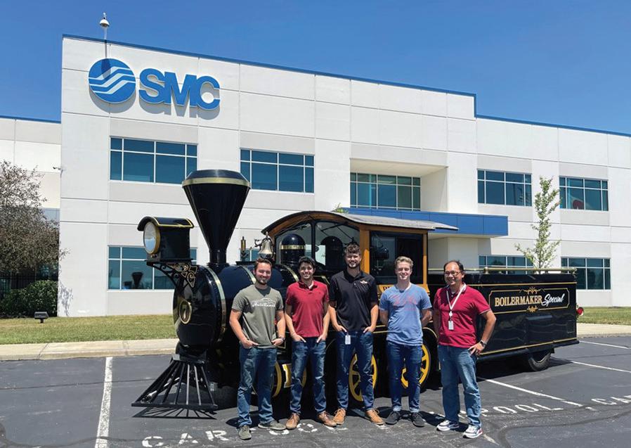
SMC recently updated the pneumatic system on the Boilermaker Special VII, the official mascot of Purdue University. According to the Reamer Club that cares for the train, the Boilermaker Special is the world’s largest, fastest, heaviest, and loudest collegiate mascot. Some of these accolades can be attributed to the train’s extensive pneumatic system, which controls the horns, bells, whistles, smokestack, and cowcatcher.
The previous system was installed 20 years ago and needed an update. It was dirty and grimy, and the filter was covered in oil, which decreased the lifespan of the equipment. Therefore, the Reamer Club contacted SMC for help. SMC donated all new products and sent a team of four
Boilermaker Special VII | Courtesy of Larissa Leck

www.fluidpowerworld.com 10 • 2022 FLUID POWER WORLD 17
DESIGN NOTES
engineers, including Purdue University alumni, to collaborate with the Reamer Club and design a new system.
The engineering team examined the existing pneumatics to understand and scope new design requirements. The system included cylinders and valves that supported the horns, cowcatcher, floating axle, and CO2 for the smokestack. The team measured cylinder lengths and space constraints for the air preparation system and valves, performed flow testing, and assessed electrical needs. They also considered the outdoor environment that the system would need to withstand during home and away sporting events, as the train was often exposed to rain, snow, road salt, and harsh conditions.
While researching the horn’s required flow for maximum performance, the team was conscientious so that the horn’s sound would not cause hearing damage to nearby ears. “We were able to specify the flow rate to be about 100 lpm higher than what the system was currently, which allowed the horns to be just below the threshold of pain,” said Michael Spicklemire, project lead and design engineer in SMC’s United States Technical Center.
The new air preparation system installed in the coal car behind the cab is SMC’s AC-D series modular air preparation unit for filtration, water separation, and lubrication. It includes a safety dump ball valve controlled by a switch on the cab’s control panel and a VHS series manual shutoff valve. The VHS series provides a convenient means of isolating supplied pressure in a pneumatic system and exhausting downstream pressure for maintenance purposes. The units can be locked in the exhaust position and are an integral part of an energy isolation system.
A 12-station VQC 4000 series valve manifold directs the air to the horns, bell, whistle, and two air cylinders. One air cylinder at the front of the train raises the cowcatcher when pressurized, and the cowcatcher lowers by gravity when unpressurized. Another cylinder located in the coal car actuates a lever that releases CO2 from two tanks and exhausts it through the smokestack.
A control panel inside the cab includes light-up switches and buttons for each horn, the CO2, and the safety dump valve, allowing the driver to stop all air pressure immediately.

SMC also provided new tubing, wiring, fittings, and updated schematics for the Reamer Club’s operator manual.

“Many SMC engineers graduated from Purdue, so this project feels very full circle for us,” said Aaron Pfeiffer, an engineer in SMC’s United States Technical Center. “It has also been a great way to connect with the next generation of engineers at Purdue.” FPW
SMC | smcusa.com
18 FLUID POWER WORLD 10 • 2022 www.fluidpowerworld.com
A team of SMC engineers, including a few Purdue University alumni, donated 1,000 working hours and new components to update the Boilermaker Special VII’s pneumatic system.
| Courtesy of SMC
The 12-station VQC 4000 series valve manifold directs the air to the horns, bell, whistle, and two air cylinders.
| Courtesy of SMC
The AC-D series modular air preparation unit removes moisture and debris from the pressurized air and includes two shutoff valves to stop air flow immediately.
| Courtesy of SMC
LEAD TIMES OF HOURS INSTEAD OF DAYS OR WEEKS.
With today’s logistics challenges and stretched lead times, we’re here for you with our Hydraulex Reman™ line. Remanufactured pumps, motors and valves engineered to deliver OEM level performance and that carry an industry-best 24-month warranty. With our unmatched on-the-shelf inventory of units and parts, and our ability to convert or build units in hours instead of days or weeks, we’re sure to have the unit or part you need right now. Speed and availability redefined. Put a Hydraulex Reman™ unit to work for you.

1-800-422-4279 sales@hydraulex.com www.hydraulex.com COME SEE US AT BOOTH: A3.207
DESIGN NOTES
Edited by Rachael Pasini • Senior Editorhuman motion derive air from walking Wearable pneumatic actuators that assist
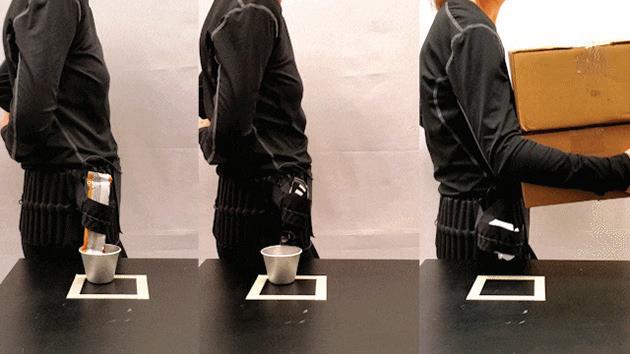
Mechanical engineers at Rice University’s George R. Brown School of Engineering built a pneumatic arm-like device that can grasp and carry small objects using a textile-based energy harvesting system. This lightweight robotic limb is intended to assist individuals with limited mobility and is tough enough for everyday use.
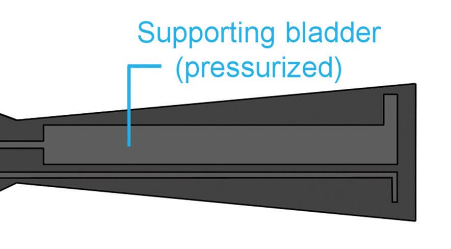
The pneumatic “arm” consists of heatsealable fabrics stacked together to form two separate bladders. The actuation bladder extends away from the body when unpressurized and curls and deflates when pressurized. The supporting bladder remains pressurized to mechanically support the actuation bladder. The arm’s surface has an elastomer lining to maintain its grip on slippery objects.
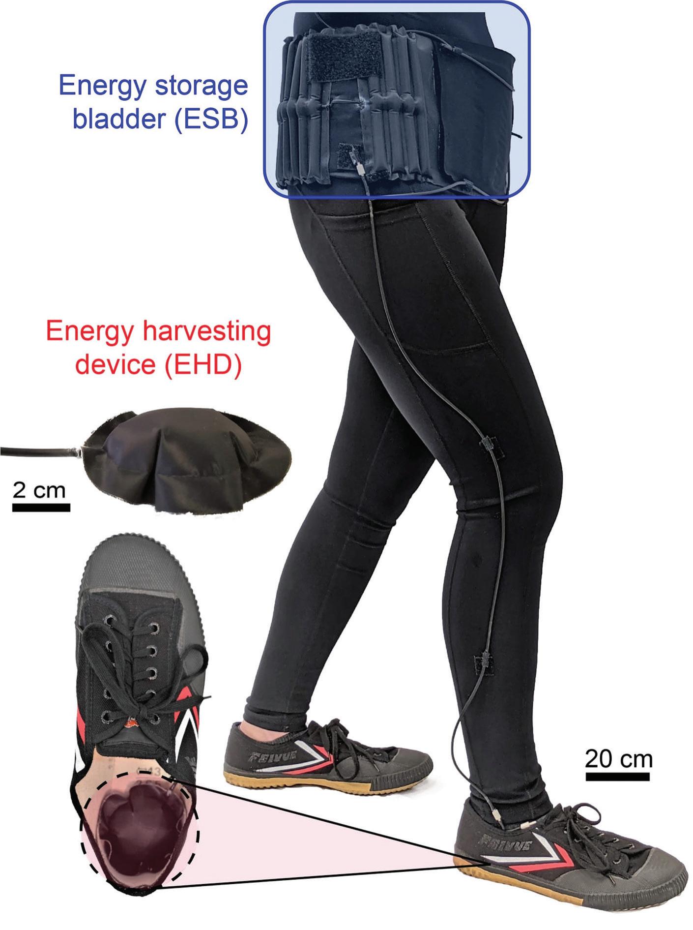
Textile pumps embedded in the soles of walking shoes harvest air pressure produced when the wearer steps down. The pumps are small, comfortable to walk on, and filled with open-cell polyurethane foam to recover their shape after every footfall. An energy storage bladder around the waist stores the pressurized air, and the pneumatic actuator applies the pressure when the wearer activates the arm.
“We chose a pneumatic approach for our wearable energy harvesting system to reduce weight and maintain comfort,” said Daniel Preston, assistant professor of mechanical engineering. “The entire system weighs only 140 grams, less than 10% of the weight of comparable electronic approaches.”
For demonstrations, the wearer currently uses a switch to operate the arm, but future versions could have sensors that anticipate the wearer’s intent and perform the movement.
20 FLUID POWER WORLD 10 • 2022 www.fluidpowerworld.com
Engineers at Rice University built a lightweight, textilebased energy harvesting system that uses pneumatic actuators to pick up and carry small objects.
| Courtesy of Preston Innovation Lab/Rice University
The actuation bladder extends away from the body when unpressurized (left) and curls toward the body when pressurized (right).

Lab tests showed that the device produces the equivalent of 3 W of power with a conversion efficiency of more than 20%, outperforming electromagnetic, piezoelectric, and triboelectric strategies for foot-strike energy harvesting.
Components for a single device cost the lab about $20. The device is simple to assemble and robust enough to withstand a washing machine with no performance degradation.
“The fabrication approach uses techniques that are already employed in the garment industry, things like cutting textile sheets and bonding them with heat and pressure,” said Preston.
Along with test units, the lab also developed mathematical models to predict how well the assistive device would perform based on body weight, walking speed, and other parameters so that, in the future, they can optimize performance for specific user groups.
The pneumatic arm is just one of several ideas that Preston’s lab team has designed and implemented. Inspired by spiders’ natural hydraulic limb systems, they created “necrobotic” grabbers from dead spiders that can pick up and move small items. They also built a shirt with a bellowslike actuator attached at the armpit that expands, enabling the wearer to pick up a 10-lb object.
“Census statistics say there are about 25 million adults in the United States who find it difficult to lift 10 lbs with their arms,” said Anoop Rajappan, a postdoc
| Courtesy of Preston Innovation Lab/Rice University
10 • 2022 FLUID POWER WORLD 21
DESIGN NOTES
The arm curls in the storage position (left) and extends in the unactuated position (center). In the actuated position, the arm curls toward the body while the supporting arm remains pressurized (right).

| Courtesy of Preston Innovation Lab/Rice University
supported by the Rice Academy of Fellows. “That’s something we commonly do in our daily lives, picking up household objects or even a baby.”
Tests on mannequins showed that the armpit actuator
could lift an object without assistance from human muscles.
With their energyharvesting system and pneumatic actuators, Preston’s lab team is thinking about how to translate their work into wearable
quality matters. every time.

DURABLE. RELIABLE.
HOSE, CORD, & CABLE PRO GRADE REELS


FOR:
WATER
coxreels
also be in Preston’s future to keep wearers from resembling the Michelin Man.
“We’ve managed to keep it quite low profile, but yes, that’s definitely something to think about, especially with the actuators,” said Preston.
products like gloves that help people close their hands. They are also thinking about portability and how to redesign devices that rely on rigid, bulky power supplies and are either uncomfortable or tether people to external infrastructure.
“We’re also thinking about devices like pneumatic actuators that apply therapeutic compression for things like deep vein thrombosis — blood clots in the legs. Anything that requires air pressure can be powered by our system,” said Rajappan.
Conversations with fashion consultants could
Fluidic actuation underpins most new technology in the growing field of soft robotics. Pneumatic actuation is particularly preferred in soft wearable robots and devices that assist human motion to enable lightweight, comfortable designs. Preston expects to see widespread use of commercially available assistive technologies that rely on pneumatic actuation within the next decade. FPW
Preston Innovation Laboratory pi.rice.edu
The pneumatic actuator serves as a third arm while the wearer’s hands are full.
| Courtesy of Preston Innovation Lab/Rice University
www.
.com AIR /
| HYDRAULIC | PNEUMATIC |
VACUUM
|
WELDING
|
POWER
SOLUTIONS
AND MORE
22 FLUID POWER WORLD 10 • 2022


Pneumatics is a fluid power technology that transmits force through a pressurized medium to create useful work. In the simplest explanation, air will compress to half its volume when subjected to double the pressure. PNEUMATICS CLASSROOM Sponsored by: Brought to you by: LEARN MORE AT: www.fluidpowerworld.com/pneumatics-classroom CHECK OUT THIS NEW CLASSROOM COVERING: • A Practical Guide to Pneumatics • How to Size a Pneumatic Cylinder • Automation at Work • Improving Pneumatic Energy Efficiency + more
Edited by Rachael Pasini • Senior Editor
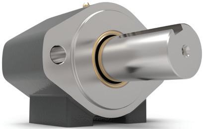
Slip rings make continuous rotation
possible in hydraulic machinery

Slip rings are small but mighty devices that serve multiple purposes and can be used in various industries. They come in different types, shapes, and sizes and are installed where the stationary part of a machine meets a rotational part.
Basic designs include rings that rotate with the rotating part of the machine and static brushes that slide along the ring during rotation. The assembly keeps the equipment intact while enabling smooth operation and power or signal transmission. With many purposes and uses, slip rings are now in almost any device with stationary and rotary components.
How slip rings work in hydraulic systems

In hydraulic systems, slip rings help transmit fluid in the most demanding applications where continuous rotation is required. They connect fixed and rotary hydraulic pipelines and provide 360° motion without interference. Hydraulic slip rings, also known


Mobile machines like excavators use hydraulic slip rings for 360° rotation.

| Courtesy of Moflon
as hydraulic swivels or rotary joints, typically include a housing, shaft, bearings, rings, and seals. This self-contained assembly prevents leakage, error, and damage to the stationary and rotating parts.

Hydraulic slip rings have a two-in-one purpose. Besides providing a smooth flow of fluid — such as coolant, gas, water, or steam — they can also transmit signals and combine multiple wires in a single assembly without damaging the wiring. They can also enhance functionality by providing
adequate pressure between components. Some variations include sensors to measure operational parameters, such as speed and temperature, and provide feedback on the slip ring’s condition.
Most hydraulic slip rings are automatic and well-adjusted to hydraulic systems’ working temperatures, pressures, and other factors. They can also be remotely controlled and installed in different machine parts. Mobile equipment like excavators, bulldozers, and dump trucks are some of the most common hydraulic machines that rely on slip rings. Such machines must rotate a cab and hydraulic components 360° in either direction without losing pressure or power. Hydraulic slip rings are also used in robotics, packaging, wind turbines, medical equipment, oil and gas equipment, metal construction, plastic molding, and aerospace — any application that requires continuous rotation.
Types of hydraulic slip rings
There are three main hydraulic slip ring types: integrated, semi-integrated, and separate. Integrated slip rings reside in the steel construction of hydraulic machinery, which provides a rugged structure for better durability and performance. Semi-
FUNDAMENTALS 24 FLUID POWER WORLD 10 • 2022 www.fluidpowerworld.com
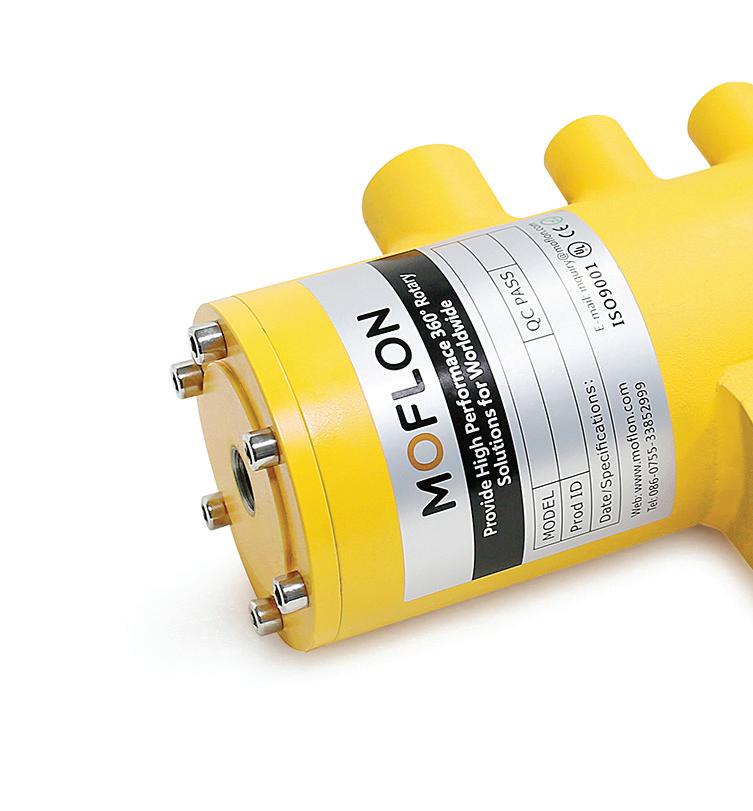
Moflon customizes hydraulic slip rings to meet environmental and operational conditions and application requirements.
| Courtesy of Moflon
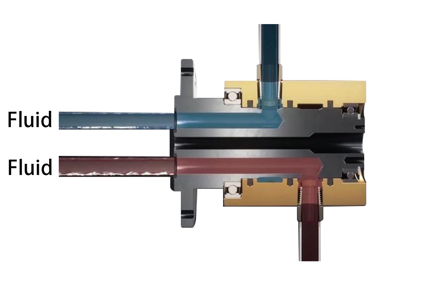
HOUSING SHAFT
FLUID SEALS
Hydraulic slip rings connect stationary and rotating parts to transmit fluid without interference.
| Courtesy of Moflon
integrated designs lack a mounting tube and offer better access for maintenance. Separate hydraulic slip rings can be assembled and installed with conventional slip rings and consist of a variable mounting tube. Most slip rings on the market transmit liquid, gas, power, or signal. Companies like Moflon also provide options for fiber optic and high-frequency transmissions and offer different sealing and shaft types to accommodate a variety of operating conditions. Variations for high speed, low torque, high pressure, high flow volume, and other parameters can be tailored for specific application requirements.
Slip rings can help overcome mechanical issues, provide better

performance between machine parts, and simplify system operation. In hydraulics systems, they afford smooth operation under heavy loads and high capacity in overload conditions. They can even help adjust the speed of rotation via the resistance. Since slip rings are welltested and proven solutions, they can fit many different purposes, needs, and industries. FPW
 Moflon moflon.com
THINK? WHAT DO YOU
Connect with thousands of engineering design professionals online.
BEARING FLUIDBEARING
BY: Tracy Jones • Director of CJ Plant Maintenance
Four signs your hydraulic

pump needs to be rebuilt
The challenge with hydraulic pumps is that they are often neglected until something goes wrong. You wouldn’t be blamed for not knowing how often you need to service your hydraulic pump or how often it needs maintenance. However, some common signs indicate when your pump needs to be rebuilt instead of just serviced. If any of the following statements apply to your pump, then it’s time for a rebuild
1. Your hydraulic pump is noisier than normal
The noise could be from the internal parts rubbing together or from hydraulic fluid rushing through the system. Perhaps it is worn out or there is too much load on the pump. A worn-out pump will have higher internal friction than a new pump, causing extra noise. In addition, a worn or damaged pump may not be able to handle a high load without heating up. This will make it vibrate more and increase pump noise. If you hear humming or grinding noises from your pump, it is important to investigate the cause immediately because it could be very serious.
2. There is a lack of fluid in the tank
First, you should check the fluid level when your machine is off. If the fluid level is below the normal mark, the pump may not be returning all the fluid to the tank. If you notice that the fluid level is at the top while the machine is off, it could be that the pump is not drawing enough fluid. If the pump is operating normally and the fluid level is low, there may be a leak in the system.
3. You notice a strong odor coming from the pump

A hydraulic pump is enclosed, and many of the internal parts are made of metal. The metal parts are subject to corrosion and some wear. This means that your pump can leak hydraulic fluid from time
to time. When fluid leaks from the pump, it will smell, and there will be a puddle of fluid on the floor, where the pump is located. A bad smell coming your hydraulic fluid can be an indication of dirty, contaminated oil and failure of the internal pump components.
4. The output pressure of your pump is erratic
When a pump is new, it uses some of the fluid in the system to build up pressure. As the pump ages, it uses more fluid. If the pump is running but the pressure is lower than normal, it could be a sign that the pump is worn out. When you are operating your machine and the pressure drops, it is best to stop the machine and investigate. If the pressure is high, but well below normal, it could be that the pump is not drawing enough fluid and the pressure is high because there is too little fluid in the system.
Conclusion
Whatever the reason, if your pump is worn out, it is time to rebuild it. A worn-out pump will not be able to do the job it was designed to do. It may be unable to provide the necessary pressure or flow rate, or it may just fail when you need it most. When your pump is worn out, you need to have it rebuilt or replaced. A worn-out pump is also a safety hazard because it may not be able to handle the necessary pressure or flow rate.
CJ Plant Maintenance | cjplantmaintenance.com
THINK? WHAT DO YOU
FPW
A technician works on a hydraulic press.
| Courtesy of Adobe Stock
26 FLUID POWER WORLD 10 • 2022 www.fluidpowerworld.com MAINTENANCE
Connect with thousands of engineering design professionals online.
The #1 Trade Show & Conference for Fluid Power
Power Transmission, and Motion Control
CO-LOCATED WITH CONEXPO-CON/AGG (two shows, one price)


The International Fluid Power Exposition (IFPE) is the place where engineers meet to:
Spark new ideas with in-depth technical conversations with other engineers.
Discover solutions current suppliers can offer to your unique challenges.
Find new partners among suppliers pushing the envelope on what fluid power can do.
CONNECT WITH TOP MANUFACTURERS
Danfoss Power Solutions
Including Bosch Rexroth
Parker Hannifin
Poclain
IFM Efector

Hawe Hydraulik , Husco , and 375+ more!
Join your peers from these OEMs:

Caterpillar Inc
Volvo Construction Equipment
Liebherr
CASE Construction Equipment
Komatsu
John Deere Construction
Doosan Bobcat
KOBELCO Construction Machinery USA
Company
“ There’s no other show in the world I think that brings the OEM machine manufacturers and the suppliers as close together as this show. It’s a good place to meet and learn about what’s going on. In the Americas, in the Western Hemisphere, this is the show for fluid power.”
KEN ROSENBECKER SALES MANAGER NORTH AMERICA | WIPRO INFRASTRUCTURE ENGINEERING


IFPE only happens once every three years!
REGISTRATION OPENS EARLY AUGUST
See why IFPE is the can’t-miss fluid power event of 2023! Learn more at IFPE.com


FLUID POWER EXPO
MARCH 14-18, 2023
LAS VEGAS, NV, USA
INTERNATIONAL
,
,
,
,
,
∙
∙
∙
∙
∙
∙
∙
∙
∙ LBX
,
Ron Marshall • Contributing Editor

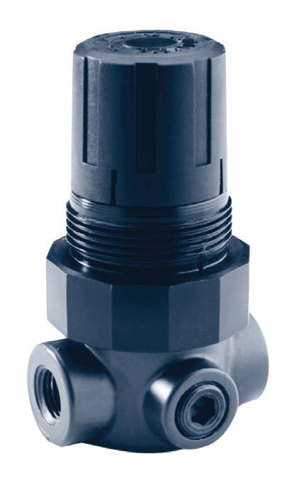
Dealing with fi lter gauge issues
Air filters very often have differential gauges installed on them to help compressed air system operators detect when the element needs changing. It is very important for maintenance personnel to change the element when it is required.

Having high pressure differential causes the air compressor energy input to increase by about 1% every 2 psi of pressure — so not changing filters can be costly. The pressure differential can also cause problems with compressor control, with compressors rapidly cycling themselves to death, and sometimes causing high oil carryover and higher energy consumption.
High pressure differential is a sign the filter is reaching the end of life. If ignored, the pressure loss can actually go away as the internal element collapses; when this happens, contaminants can pass directly downstream, causing quality problem with the product.
It is important to realize the pressure gauge reading varies with the square of the pressure change. This means that if a filter is rated for 200 cfm, but is only passing 100 cfm, the gauge will read about one-quarter of its normal value. This increases the chance a filter that needs to be changed may go unnoticed by maintenance staff.

And of course, there are some gauges that are sealed within the filter housing, which means there is no method of testing them. With these products, sometimes the needle will stick or actually fall off the rails like the one in the graphic.
It is best to use the gauge only as a guide, but also change the filter at least once per year, even if the pressure reading shows that things look within a proper operating range.
ENERGY EFFICIENCY
FPW 28 FLUID POWER WORLD 10 • 2022 www.fluidpowerworld.com
This differential pressure gauge has become damaged and does not work.


FOR YOUR MOST DEMANDING APPLICATIONS TRUST YUKEN WHERE OTHERS HAVE FAILED, WHERE OTHERS FEAR TO GO, OR WILL NOT GO. BE IT IN • WIND POWER • INJECTION MOLDING • LUMBER MILLS • STAMPING PRESSES • GEOPHYSICS • SHIPPING UNEXCELLED IN SPEED AND LIFE YOU CAN TRUST YUKEN PROPORTIONAL VALVES, LINEAR SERVO VALVES AND SERVO-CONTROLLED SYSTEMS. ALA INDUSTRIES LIMITED 3410 Delta Dr • Portage, IN 46368 Tel: 877-419-8536 Fax: 219-762-2066 www.alaindustrieslimited.com
Electrichydraulic hybrid systems reduce emissions in refuse collection vehicles


 reduce emissions vehicles
 by Rachael Pasini, • senior Editor


WORLD 10 • 2022 www.fluidpowerworld.com MANAGEMENT
bridge the road to electrification with small batteries and readily available
components.

vehicle emissions that degrade air quality and negatively impact public health. From a technical standpoint, electrification makes sense for light- and medium-duty vehicles, such as cars and small construction equipment. However, electrification is more complex for larger vehicles in high-power and high-range applications where maximizing
payload is critical.
Many jurisdictions have ambitious electrification goals for heavy-duty vehicles, such as refuse collection vehicles, which contribute significantly to overall emissions. Though the push for electrification is noble, it’s difficult to overhaul an entire fleet of engine-based refuse trucks without the supporting infrastructure. It’s also difficult to part with hydraulics for electric alternatives


that add weight and maintenance.
Refuse vehicles like the automated side loader (ASL) are designed around the truck chassis and demand more from electrification than passenger cars. For these vehicles, the primary energy source powers the driving, load transportation, and hydraulic functions. A traditional ASL carries about 15,000 lb of garbage and uses a hydraulic system to pick up 1,000 to 1,500 trash cans daily while compacting the load. Electrifying this vehicle is possible but requires a large battery, which decreases the truck’s payload.
For such applications, an electric hybrid system combines the advantages of electric solutions, such as smart energy usage and lower emissions, while capitalizing on the performance and range of a traditional diesel engine.
Parker Hannifin Corp. proposes a hybrid system that can be implemented with readily available components and a small battery pack without revolutionizing the chassis architecture. The system relies on the diesel engine for driving and an electric motor for hydraulic functions. The idea is to optimize components based on operation conditions to reduce emissions without
compromising payload.


www.fluidpowerworld.com FLUID POWER
contribute
passenger powers functions. pick
10 • 2022 WORLD
Parker’s electric hybrid system can be implemented with readily available components. Shown here are the GVM 210-100 PMAC motor, P1M-065 piston pump, Chelsea 890 hot shift PTO, GVI inverter, and L90 LS valve.

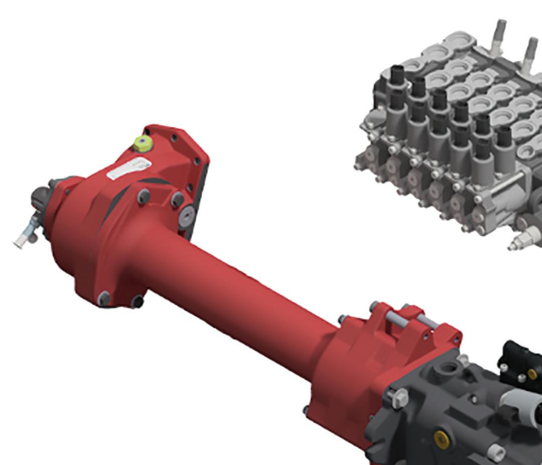
Let hydraulics do the work
Parker’s electric hybrid design uses a traditional ASL chassis and doesn’t replace the engine with an oversized battery. It also doesn’t replace hydraulic functions with electromechanical alternatives.
Hydraulics technologies have advantages that electromechanical actuation lacks in ASLs and other refuse collection vehicles. First, hydraulic cylinders are generally lighter in weight than electromechanical assemblies. If an ASL has a linear actuator and motor, the arm must lift the added weight of the assembly in addition to the load. “Even if the system is more efficient because there are no hydraulic losses, if you think about lifting 1,000 cans per day with the added weight, that’s a lot of energy wasted,” said Germano Franzoni, Senior Systems Engineer at Parker. “The power density, especially for suspended weight, is very important.”
Another advantage of hydraulics is the ability to distribute power among different functions. For example, if an ASL has a hydraulic system of 40
hp and five functions that run continuously, a valve can split the power from a single pump and distribute it among the five actuators. Electromechanical assemblies can’t split power like hydraulics and might need up to 120 hp to perform the same work.

Also, hydraulics are accustomed to corrosive and dirty environments, whereas electromechanical actuators are more delicate and less tolerant of such operating conditions.

“The number one maintenance item in refuse vehicles is the cylinders because the duty cycles are very intense, and there’s a lot of shock and vibration,” said Franzoni. “If you want to change a cylinder or rework the seals, it’s a relatively quick and inexpensive maintenance item. But if you need to replace an electric actuator, that’s a much more complicated part in terms of cost and maintenance.”
A traditional ASL collects garbage cans with a hydraulic arm,
and the packer continuously runs to compact the load inside the vehicle body. During collection, the pumps rotate at low speeds, and the truck engine is idle and loaded to prevent stalling. This operating condition is inefficient and produces noise and higher emissions.
With Parker’s proposed electric hybrid system, the engine isn’t loaded while idle. When the ASL stops at a house to pick up a garbage can, an electric motor runs the hydraulics and relieves the engine, which increases efficiency and reduces fuel consumption, emissions, and noise.
“When the engine works at idle, it’s the worst point for efficiency and emissions,” said Franzoni. “We think hybrid is the right solution, where hydraulics are still on the truck, but the hydraulic pump isn’t run from the engine — it’s run from an electric motor, which also serves as a generator while the truck is driving.”
Hybrid system operation and design
Parker suggests using a hydraulic pump with a thru-drive configuration that is piggybacked to a permanent magnet electric motor. This subassembly is mounted on the truck’s transmission using a traditional clutch-shift power take-off (PTO). The electric motor is controlled via an inverter that derives power from a compact battery pack.
When the electric hybrid ASL stops to collect garbage cans, the PTO de-clutches from the engine, and the electric motor drives the pump. The truck engine can either idle without being loaded or come to a complete stop, and the pump can run at optimal speed (1,800 to 2,200 rpm) to reach maximum efficiency. As the truck drives between stops, the PTO engages, the pump runs the packer function, and the electric motor works as a generator to recharge the battery. The electronic control unit can modulate the instantaneous amount of charge depending on driving conditions to maintain good traction at the wheels.
The electric motor is the first design consideration for hybrid systems. Usually, electric motors operate most efficiently at high speeds. But when driving and operating an ASL, hydraulic components can limit the motor speed. Therefore, selecting an electric motor that is configurable and adaptable to the hydraulic components’ operating conditions is essential.
As for sizing, the battery can be relatively small, and the pump size can be reduced by half because its speed is no longer tied to the engine's idle condition. The system can be designed with different pump and valve
32 FLUID POWER WORLD 10 • 2022 www.fluidpowerworld.com WASTE MANAGEMENT
L90 LS valve
GVI inverter
GVM 210-100 PMAC motor
P1M-065 piston pump
Chelsea 890 hot shift PTO
technologies depending on the arm geometry and the type of control required.
Parker tested its electric hybrid design concept by sending an ASL on a route through a dense suburb in Detroit. The team recorded the engine and electric motor speeds, hydraulic arm pressure and flow, packer pressure and flow, and battery charge during the test. The results showed that the battery remains well charged even when driving phases between pickups are short.
The test started with a fully charged 96 V battery with a stored energy of 10.4 kWh and weighing 238 lb (107 kg). The ASL had a single P1M 65 cm3/rev piston pump with LS controls and electric torque limiting supplying flow to an L90 load sensing valve bank where the arm sections were prioritized over the packer sections. The electric motor was a Parker GVM-210-100 with a peak torque of 110 lb-ft (150 Nm). The motor was controlled using a Parker GVI inverter.
As the ASL drove from house to house, the electric GVM motor served as a generator to charge the battery. The duration of the
driving phase depended on the distance between houses, traffic, traffic lights, and other factors. When approaching a garbage can, the driver activated the dead-man trigger on the joystick, the PTO de-clutched, and the GVM motor turned the pump based on flow demand (500 to 2,000 rpm). By the end of the test, the ASL completed more than 300 garbage can pickups without significantly long driving phases, demonstrating that the battery recharged adequately between frequent stops.
The future of electric hybrid systems
Parker’s design and test show that decoupling the engine from the hydraulic functions improves efficiency, integrates easily with engines and standard truck chassis, and reduces component size, noise, and emissions.
But the benefits are not limited to ASLs.
The system can easily be adapted to similar applications, such as residential front-end loaders (FEL), where the hydraulic arm is installed on a cart attached to the truck’s forks.
Despite the range of applications, electric
hybrid systems are still displaced in today’s market, which favors fully electric vehicles. Governments are calling for zero-emissions by target dates and providing funding to produce and purchase fully electric fleets. Regardless of what makes sense from a technical standpoint, there’s no money set aside for hybrid systems.
The original roadmap placed hybrid as a bridge toward electrification. While waiting for infrastructure and battery innovation to meet the demand for fully electric vehicles, hybrid systems provide a right-now solution without much disruption. However, electric hybrid implementation has been postponed until the market shifts.
“We see a space for hybrid in the future,” said Franzoni. “We just don’t know exactly when or how.”
Parker Hannifin Corp. | parker.comTHINK? WHAT DO YOU
Connect with thousands of engineering design professionals online.
In Parker’s high-level electric hybrid system schematic, the valve layout can change based on the truck and application requirements.

www.fluidpowerworld.com 10 • 2022 FLUID POWER WORLD 33
FPW


Overhung Load Adaptors • Provides Radial and Axial Load Support • Extends Motor/Pump & System Lifetime • Seals Out Dirt and Contamination • SAE A-F and non-SAE Mount Options • Standard Models / Fully Customizable • Engineering Assistance / Fast Delivery www.zero-max.com 800.533.1731 RELIABLE.ROBUST.AVAILABLE. RADIALRADIALOVERLOADS LOADSUPPORT AXIALLOADSUPPORT
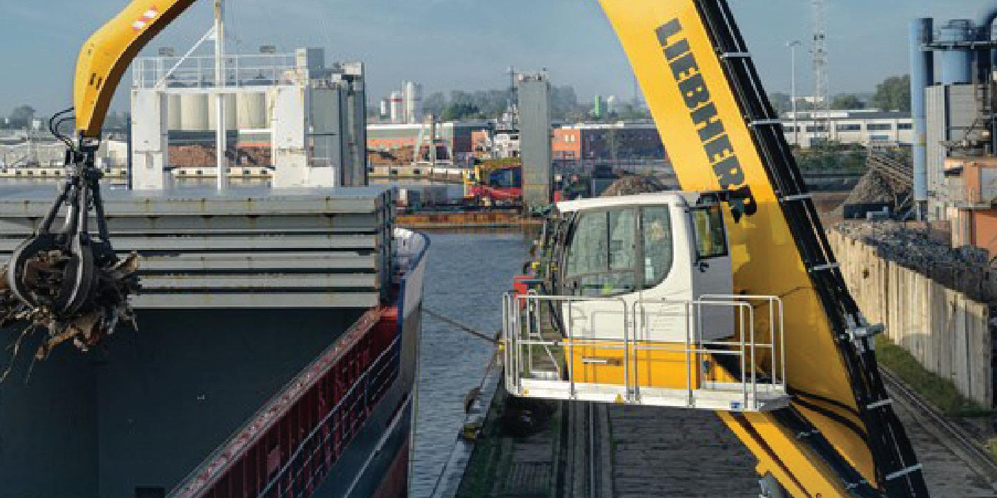
MOBILE MATERIAL HANDLING


JOSH COSFORD • CONTRIBUTING EDITOR

are some of the most widespread hydraulic applications developed. Where you must move product or material, a hydraulic machine is available to help. Industrial material handling often involves lifting, rotating, flipping, or moving products. The movement may lie within a process, such as a bin tipper that fills a hopper or the straightforward relocation of finished material.


Mobile material handling offers users a more diverse selection of machinery. The possible applications are focused on moving materials such as stone, lumber, scrap metal, recycling, freight, and produce, just to name a few. Although by all means no industry standard, a common material handling platform looks much like an excavator. With tracks or wheels and a large boom attached to a slew-driven body, it’s easy to confuse these versatile machines with their cousins. Literally called “material handling machines,” these versatile hydraulic vehicles offer a solution to many material handling challenges.

www.fluidpowerworld.com 10 • 2022 FLUID POWER WORLD 35
MOBILE MATERIAL HANDLING


Elevated, adjustable cab allows easy reaching
The elevating cab is common to mobile material handling machines, which provides a field of view high above the ground to provide a bird's-eye view of the work area. The adjustable-height workstation rests low like an excavator, yet using hydraulic cylinders will lift the boom many feet higher. The elevated perspective gives the operator a better view of the scrap piles, dump truck bodies, compactor hoppers, or lumber piles.
The adjustable cab height allows easy work in locations difficult for other machinery to reach, such as over a fence where arborists have felled and sawed a tree.

High-lift machines offer an additional 6 ft or so for more extreme height requirements by elevating the entire slewed portion of the machine (Figure 1).
Limiting horsepower
Every actuator on material handling machines is hydraulically powered; the arm, boom, slew, drive, and grapple. Using the same horsepower-limiting, load-sensing hydraulic piston pumps as excavators, these systems provide powerful, efficient hydraulics offering the highest possible combination of power and speed for any given power output. The horsepower limiting pump uses an extra internal valve that caps the power output of
the pump regardless of demand. Essentially, this pump always offers maximum flow until load pressure rises above the power setting, which is a product of pressure and flow. Pressure always trumps flow, and when the operator demands high speed and force, the pump will reduce flow (and therefore speed) to maintain maximum load capacity.
Horsepower limiting pumps have been around for some time, initially an upgrade to improve productivity. Engineers understood their size, power and weight limitations for any given machine and that only so much real estate could be hijacked by the prime mover and pump (not to mention cooling). Getting more speed or power at the sacrifice of the other has offered machinery the best of both worlds while automatically delivering maximum power output. High force tasks are delivered at slow velocity while low force tasks are accelerated.
Modern material handling machines benefit from horsepower limiting operation in more than just productivity. Sure, they benefit in applications such as scrap handling, with the power to move giant piles of scrap steel while slewing or traversing in a highly productive fashion. But in today's world of environmentally relevant design, horsepower limiting technology offers the top solution for low horsepower Tier IV Final machines offering surprising power and speed from small power units. Further
developments in horsepower limiting technology employ electro-proportional pump and machine control, but that concept is deep enough for its own missive.
High-pressure grapple loaders
"Material handling machine" may have inherited the namesake, but plenty of other machinery are up to the task. Employing grapples not unlike the prior, the grapple loader body installed on trucks makes the perfect log transportation vehicle. In forested areas, the vehicle arrives at a logging location to collect and transport lumbar to the local mill.
Truck grapple loaders offer a wide range of payload capacities, from single-axle, light truck-mounted versions to those on semitrailers. As for this discussion, the payload matters less than how it works — namely, hydraulically. Like many mobile machines, these operate at relatively high-pressure.
Hydraulic energy comes from a PTOmounted gear or piston pump, of which the latter is growing in popularity because of its efficiency. Often the grapple assembly is sold without the pump, filter and reservoir, leaving it up to the installer to coordinate.
A grapple loader assembly includes everything required to do the job — cab, boom, arm, grapple, control valves, hoses, and actuators. In addition, end users may option their machines with accessories such as oil-to-air coolers or wireless remote controllers. A wireless remote control provides flexibility to the operator, who may work high up from the command center or closer to the ground or hopper that the logs come from or are going into.
With flexibility in the work location, the operator may more precisely place logs, ensuring the maximum payload possible without gaps or spaces.
You can expect a grapple loader to handle up to 15,000 lb per load, although that number depends on many factors.
The boom angle and length factor in load capacity, and as you would expect, when the boom is straight out at full length, it cannot support the same mass. Some more advanced machines automatically control and limit the working range to prevent a
36 FLUID POWER WORLD 10 • 2022 www.fluidpowerworld.com
frightening topple. Still, care should be taken on lesser machines that require only the operator's experience.
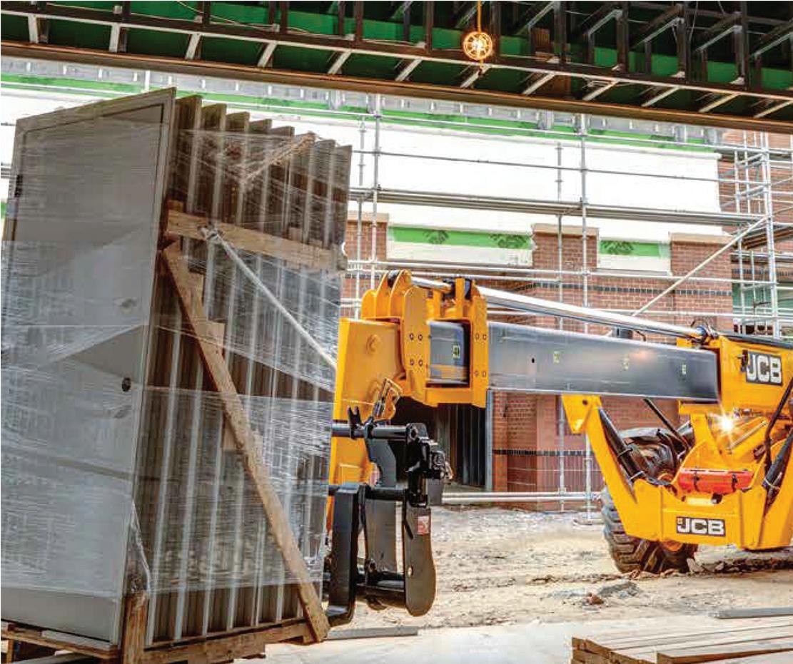
Variations in log handling technology avoid the truck-mounted, slewed systems altogether. One version (Figure 2) looks more like a telehandler than a traditional grapple loader, with a long telescopic boom mounted to the extended chassis. These machines are perfect for high-volume lumber yards, where they enjoy load capacity sometimes four times the boomoperated grapple loader. The same limits to geometry apply; the log handler quickly loads, transports and unloads dozens of logs simultaneously.
The hydrostatic drive of the log handler offers much the same advantage to other mobile machineries, such as front-end loaders or dozers. The hydrostatic pump and motor combination provides powerful and efficient fore/ aft movement control to enable rapid cycle times in a productive sawmill.
Rugged for indoor and outdoor use


Sophisticated machines employ four-wheel drive using individual wheel motors and, when combined with accumulators, may offer hydraulic hybrid drive. Imagine, instead of using brakes to slow the vehicle, the wheel-motor's swash plates swing over-center and pump into accumulators to store energy. Then, once again, during acceleration, the process reverses to power the wheels from the accumulators. A laden machine may weigh over a hundred tons, so the extreme burst of hydraulic energy not only offers acceleration impossible with direct drive but also saves fuel and reduces C02 emissions.
Material handling applications are so diverse that it's hard to cover every example. Industrial material handling often moves skids or boxes with forklifts, order pickers, or conveyor systems. Sometimes those applications require outdoor use, and mobile material handling machines won't let you down just because it's raining or snowing. For example, the self-powered mobile dock (Figure 3) offers a safe and effective method to access heavy products high upon truck beds when no forklift is available. Often, hand-bombing material is not an option, especially for skidded or heavy items.
Using a compact gas engine, much like a logsplitter, the hydraulic pump powers two hydraulic cylinders to lift the platform to gate height and automatically raise and lower the ramp plates. These ramp plates work double duty as protective cages to help keep operators safe. Valving is simple, requiring only the most elementary items — relief valve, directional valve and counterbalance valves. Also known as motion control valves, counterbalance valves prevent unintentional lowering of the platform, keeping operators safe.

What’s cool about mobile material handling applications is the nearly-exclusive use of hydraulics. Mobile machinery is still saturated with the convenient and reliable choice of internal combustion prime movers, which pairs perfectly with high-powered hydraulics. So if you need to move an object from point A to point B, there are countless mobile material handling machines at your disposal.

FPW www.jwwinco.com 800-877-8351 sales@jwwinco.com Explore our full product range online 100,000+ Parts Standard Parts. Winco. 10 • 2022 FLUID POWER WORLD 37
HYDRAULIC CYLINDERS

38 FLUID POWER WORLD 10 • 2022 www.fluidpowerworld.com
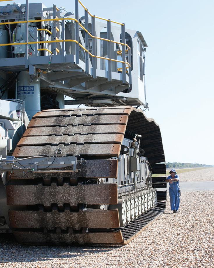
NASA RELIES ON A MASSIVE CRAWLER TRANSPORTER TO CARRY THE ARTEMIS I ROCKET AND SPACECRAFT FROM THE VEHICLE ASSEMBLY BUILDING TO THE LAUNCH PADS AT KENNEDY SPACE CENTER. COURTESY OF NASA
HYDRAULIC CYLINDERS KEEP
MOON ROCKET

INGO RÜHLICKE, HEAD OF PROJECT AND EXPORT DEPTS., WALTER HUNGER GMBH AND CO KG
Artemis I

JACKING AND EQUALIZING CYLINDERS ON NASA’S CRAWLER
TRANSPORTER HOLD STEADY THE MASSIVE LAUNCH VEHICLE.
is the inaugural moon rocket mission in a program that aims to one day return astronauts to the lunar surface. Perhaps unnoticed, but critical to success, NASA relies on two special crawler transporters to move spacecraft from the vehicle assembly building (VAB) to the launch pads at Kennedy Space Center in Florida. And in the case of Artemis I’s delayed lift-off in September due to Hurricane Ian, back to the VAB for safe shelter.
The massive transporters were originally built in 1965 to carry Saturn V rockets and Apollo spacecraft, along with the launch platform. Later
they were used for all Space Shuttle missions. But for NASA’s Artemis deep space exploration mission, using the Space Launch System (SLS) rocket and Orion spacecraft, the load capacity of the crawler transporter had to be increased by more than 50%. To accomplish this task Hunger Hydraulik developed new jacking, equalizing and levelling cylinders with greater load capacity, but also with new features to improve availability, reliability and safety.
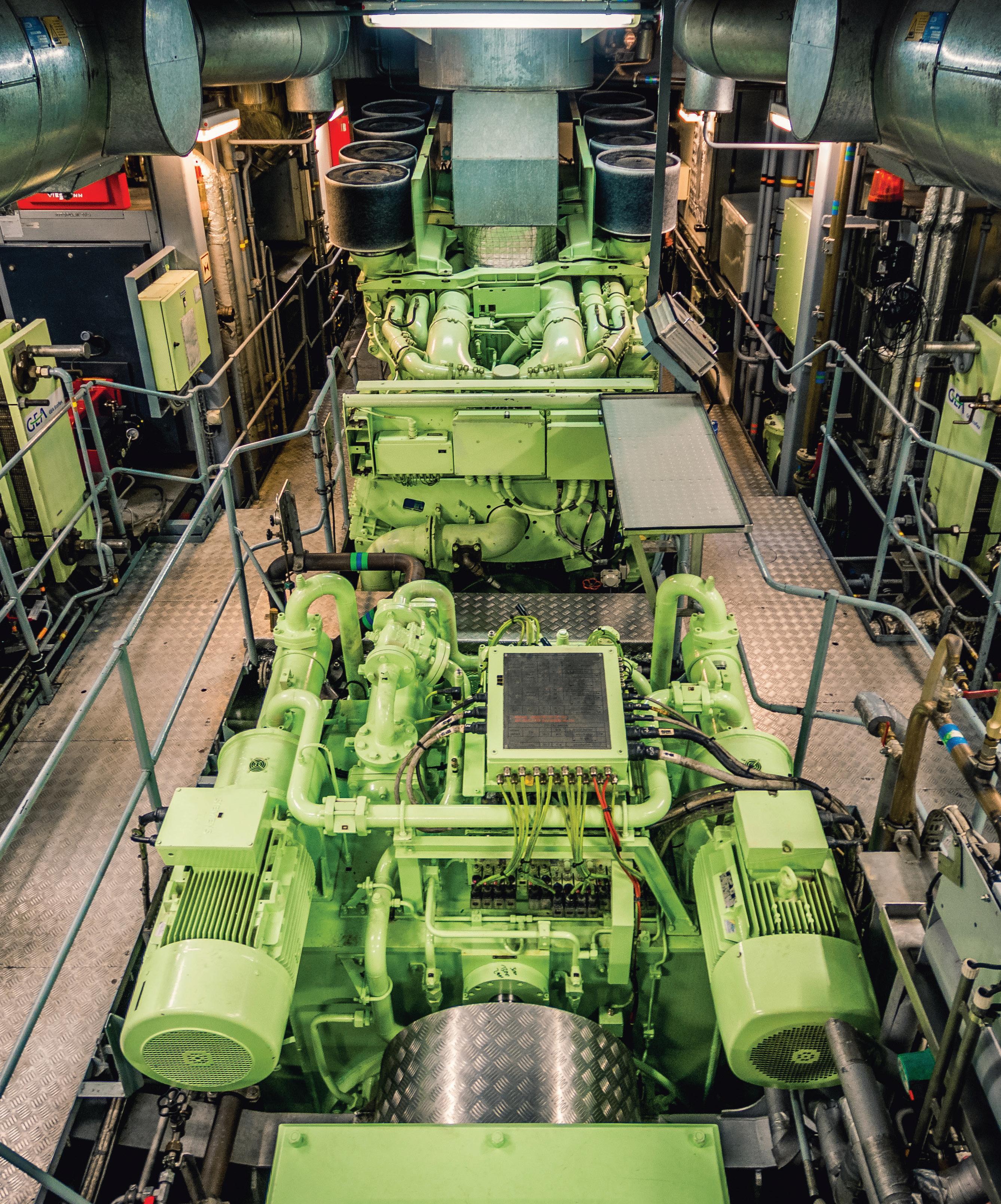
Crawler transporters
The crawler transporters are designed with eight track drives, two in each undercarriage measuring 40 m long and 35 m wide. Original maximum load capacity was 6,000 tons, handled by the hydraulic jacking, equalizing and levelling (JEL) system of 16 double-acting cylinders, four in each undercarriage. The JEL-system ensured the crawler transporter could lift the fully equipped rocket and launch platform from its parking slot in
www.fluidpowerworld.com 10 • 2022 FLUID POWER WORLD 39
ON TRACK
HYDRAULIC CYLINDERS
the vehicle assembly building, keep it level during transport, and lower it onto the launch pad. The 2-m stroke hydraulic cylinders compensated for any deviations, and were especially important when the vehicle moved up the 5° launch pad ramp. Spherical bearings mounted on the rod and cap ends of each cylinder ensured the required freedom of motion during steering and levelling.
Remote-operated valves on each cylinder provided load control, and could also hydraulically shut off a single JEL-cylinder in an emergency and maintain the load with the three remaining JEL-cylinders. A central hydraulic power unit installed in the center of the structure supplied all 16 cylinders.
Now, after 50 years of service, the crawler transporters have been completely overhauled, including new JEL-cylinders. The modifications will support human spaceflight for another 20 years.
Project scope
The design and specifications for the new JEL-cylinders were developed by NASA in collaboration with Hunger Hydraulik engineers. Besides higher load capacity, critical focuses were on heightened safety and high reliability of the system. Main requirements for the new JEL-cylinder upgrade included:
• Increase load capacity by >50% while maintaining the existing hydraulic power unit. Eight pumps each deliver a maximum 60 gpm flow at 3,000 psi to the JEL-cylinders.
• Use the same installation space and mounting interfaces in the crawler transporter.

• Improve the cylinder-to-structure interface for the spherical bearings.
• Design a multi-level safety system for hydraulic load control.
• Simplify handling and installation of the JEL-cylinders.
• Enhance corrosion protection for the piston rods in the offshore-like environment at Kennedy Space Center.
• Engineer and manufacture a one-to-one scale dynamic test rig.
New cylinder design
Based on the above parameters, the NASA/ Hunger engineering team developed a cylinder design that fulfills all these requirements. A risk analysis examined the existing JEL-cylinders as well as the proposed replacement. This considered the effects of potential failures, such as a main seal malfunction, a pipe or hose rupture, or a fracture of a spherical bearing or pin. Results indicated that the new JEL-cylinder design improves system behavior and reduces the consequences of failure, and thus ensures that transport operations are completed without delays or additional risks.
Given preliminary approval, two prototype cylinders were built to prove their manufacturability, performance and quality. The new JEL-cylinders were designed according to ASME standards with a flanged cylinder head and bottom for easy maintenance. To realize a 50% higher load capacity using the existing power unit, designers increased the cylinder diameter accordingly, to a 23-in. bore.
In light of the larger cylinder size, however, space limitations within the existing structure had to be overcome. Solutions included a switch to maintenancefree spherical ball joints instead of the original spherical bearings with pin and clevis; adaptor plates with fast-mounting
interlocks were added to the transporter structure; and a hydraulic manifold block mounted on each JEL-cylinder replaced inpipe mounted safety valves.
Even though the new cylinders lift under power and rely on gravity to lower loads, they are designed as double-acting cylinders. This offers some advantages compared to the old single-acting units. First, the loaded seal is the piston seal, which is surrounded by clean hydraulic fluid and is better protected from environmental influences. Second, the piston rod seal now acts as a secondary emergency seal if the JEL-cylinder must be used in single-operation mode. A special reconfiguration valve in the manifold block activates the emergency mode. To ensure the lowest possible load variation in this emergency mode, the rod diameter was designed as large as possible.
40 FLUID POWER WORLD 10 • 2022 www.fluidpowerworld.com
THE CRAWLER TRANSPORTER HAS A MAXIMUM SPEED OF 1 MPH LOADED AND 2 MPH UNLOADED.
| COURTESY OF NASA
THE HYDRAULIC JACKING, EQUALIZING AND LEVELLING CYLINDERS LIFT, KEEP LEVEL, AND LOWER THE ROCKET AND PLATFORM ONTO THE LAUNCH PAD. A HUNGER HYDRAULIC JEL-CYLINDER IS IN VIEW UNDER THE STRUCTURE.
| COURTESY OF NASA
PRINCIPLE OF HYDRAULIC SET-UP WITH NORMAL AND EMERGENCY MODE.
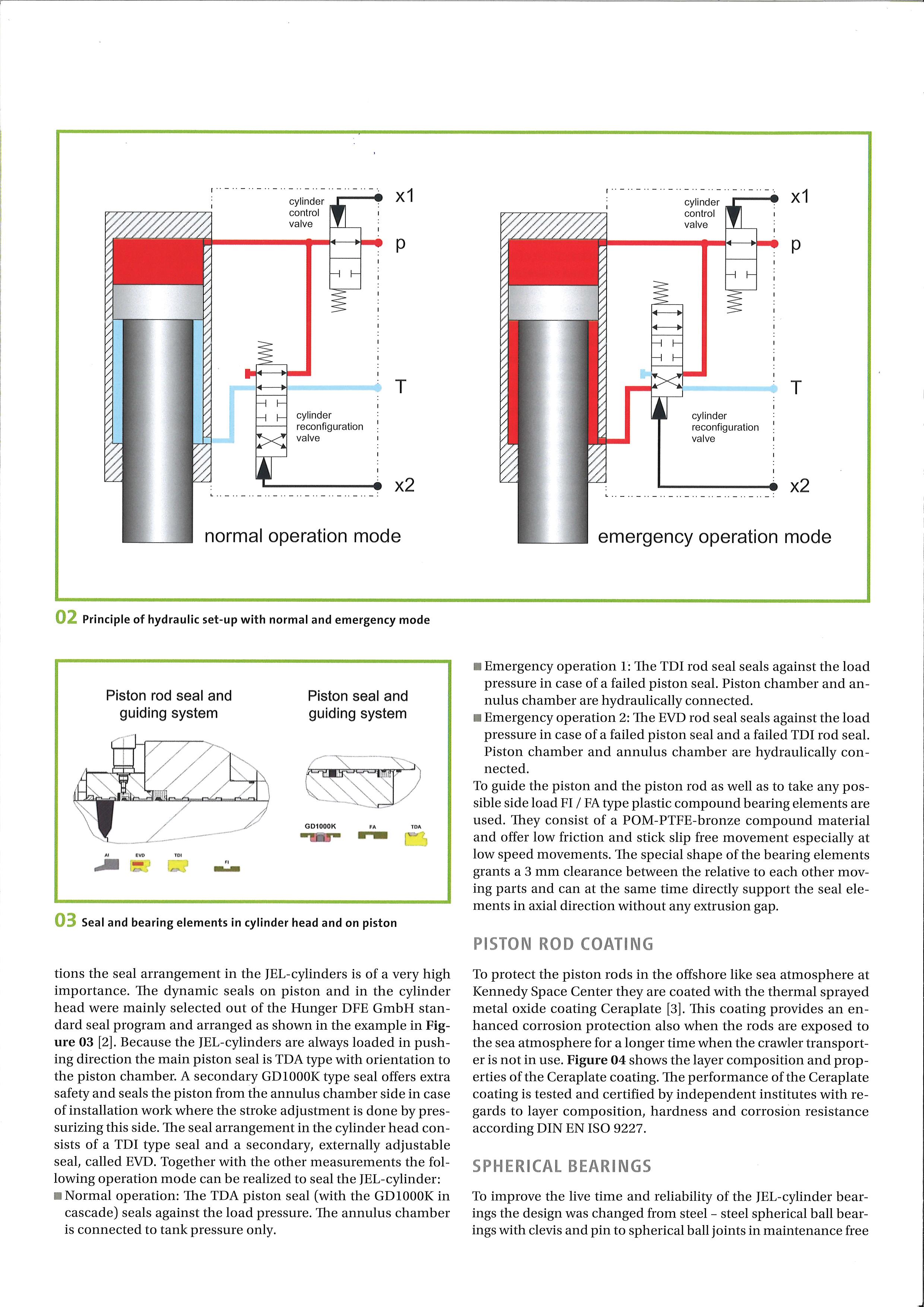
| COURTESY OF HUNGER HYDRAULICS
Sealing system upgrade
To hold a load under all circumstances and guarantee stroke movement free of stick-slip and other vibration effects, the seal arrangement in the JEL-cylinders is of a critical importance. The dynamic seals on the piston and in the cylinder head were mainly selected from the Hunger DFE GmbH standard seal catalog and arranged as shown in the nearby graphic.
Because JEL-cylinders are always loaded in a pushing direction, the main piston seal is a TDA-type oriented toward the piston chamber. A secondary GD1000K-type seal offers additional safety. It seals the piston from the annulus chamber side and permits stroke adjustment during installation and set-up. The seal arrangement in the cylinder head consists of a TDI-type seal and a secondary, externally adjustable seal, called EVD. Together, the sealing system permits the following operating modes:
• Normal operation: The TDA piston seal (with the GD1000K in cascade) seals against load pressure. The annulus chamber only connects to tank pressure.
• Emergency operation 1: The TDI rod seal seals against load pressure in case the piston seal fails. Piston chamber and annulus chamber are hydraulically connected.
• Emergency operation 2: The EVD rod seal seals against the load pressure in case both the piston seal and TDI rod seal fail. Piston chamber and annulus chamber are hydraulically connected.
To guide the piston and rod, as well as to resist any possible side loads, FI/FA-type plastic compound bearing elements are installed. They consist of a POM-PTFE-bronze material and offer minimal friction and stick-slip free motion, especially during low-speed movements. The special shape of the bearing elements grants a 3-mm clearance between the relative moving parts and can, at the same time, directly support the seal elements in the axial direction without any extrusion gap.
Rod coatings
To protect against corrosion in the seaside atmosphere at Kennedy
Space Center, piston rods are coated with a Ceraplate thermal sprayed metal-oxide coating. It includes a Ni/ Cr base layer approximately 150 μm thick and a Cr2O3/TiO2 top layer with thickness about 200 μm. Hardness of the top layer is 950 to 1,050 HV (Vickers hardness), and the surface is superfinished to Ra = 0.15 μm.
This coating provides enhanced corrosion protection during operation, and also when the rods are exposed to the sea atmosphere for extended periods when the crawler transporter sits idle. Ceraplate coating performance has been tested and certified by independent institutes with regards to layer composition, hardness and corrosion resistance according DIN EN ISO 9227.
Spherical bearings
To improve life and reliability, the JELcylinder bearings were upgraded from steel-steel spherical ball bearings with a clevis and pin to spherical ball joints. While the old bearings occasionally cracked, the new design should be more robust and withstand even overload conditions without problems.
The spherical ball joints offer an increased bearing area which reduces contact stresses in the material and the interfaces. This design is also free of bending stresses in all loaded parts. The bearing material is a maintenancefree Hunger H-Glide lining in combination with a hardened steel ball as a counterpart. It allows free tilting of 7° in any direction with a maximum
SEAL AND BEARING ELEMENTS IN CYLINDER HEAD AND ON PISTON.
COURTESY OF HUNGER HYDRAULICS
compressive strength in the H-Glide of 160 MPa (23,200 psi). An inner retention pin holds the bearing parts together. To avoid uncontrolled rotation of the JEL-cylinders, bottom-side spherical ball joints are equipped with an anti-rotation device.
Handling and installation
Because of its size, any service and maintenance of the crawler transporter is typically conducted outdoors using mobile cranes for handling heavier parts. In the case of JEL-cylinders, installation requires them to be positioned under the upper load frame structure — which is difficult if the cylinder is hanging on a crane hook. Therefore a lifting fixture was developed to allow easier handling and installation of the JEL-cylinders.

Furthermore, the mounting interface between the crawler transporter and JEL-cylinder was modified with adaptor plates with fast-mounting interlocks. The adaptor plates are only flanged to the transporter structure where good accessibility is a given. This lets technicians lift the JELcylinders in position and secure them with fast-locking wedges.
Testing the JEL-cylinders
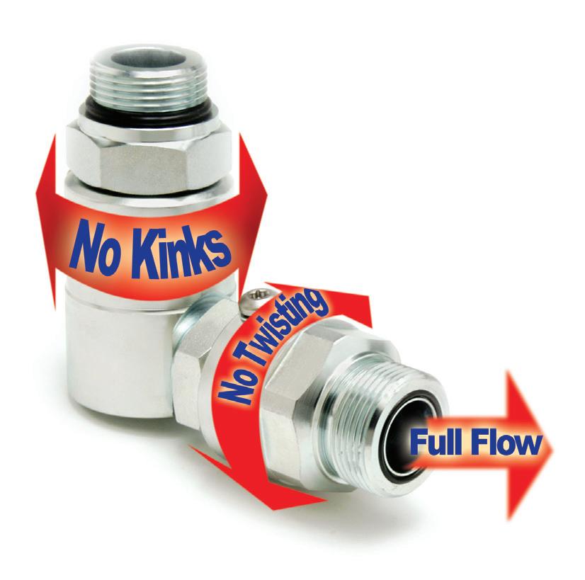
Proving the performance of the new JEL-cylinders required extensive static and dynamic full-load tests and actual application tests with the crawler transporter. Static testing carried out on a hydraulic test rig at Walter Hunger GmbH & Co. KG allowed full-pressure tests of the JEL-cylinders, not only in the end stroke positions but also mid-stroke. Additionally, all manifold block functions were tested as well as the freedom of motion of the spherical ball bearings.
To measure dynamic performance under full load, a dynamic test rig was built. It included a vertical load frame with moveable mid-support and load cylinders, a hydraulic power unit with two independent controllable hydraulic axes, along with the necessary control and recording hardware and software.
The dynamic test program involved sequences of full-stroke cycles, smaller oscillations and load variations. Also emergency load conditions were tested. During all tests — system parameters, and specific cylinder parameters like pressure, stroke, position, friction, and number of cycles — were recorded for later evaluation. Upon completion of the dynamic test program the JEL-cylinders were dismantled and inspected in detail.
Based on the findings small design adjustments were made to facilitate manufacturing of the production units, along with an evaluation of the operating life, reliability and performance of each JEL-cylinder.
To prove that the new JEL-cylinders would fit within the crawler transporter structure and function as required, the two prototype cylinders were installed in one undercarriage unit — replacing two old cylinders. This let engineers test the new handling systems plus all mounting interfaces.
After initial lifting tests, the crawler transporter was driven the 3.5 miles from the vehicle assembly building to the launch pad and back. This test drive involved cornering, lifting operations and ramp travel. The results were analyzed and necessary changes were subsequently made to the production units.
Next, a complete set of working JEL-cylinders were manufactured. One crawler transporter was completely equipped with the working JEL-cylinders and extensive test rides carried out. With final drive and load tests successfully completed, crawler transporter 2 has now been fitted with the new cylinders and is ready for current and future NASA missions.
hunger-hydraulics.com
FPW Hunger Hydraulics |
HYDRAULIC CYLINDERS 42 FLUID POWER WORLD 10 • 2022 www.fluidpowerworld.com Simplified hose configuration, less hose and adapters combine to reduce repairs and downtime, cutting the overall cost of hydraulics. 1-763-784-5531 www.SuperSwivels.com No Kinks No Hose Twisting Full Flow Quality Products Made In The U.S.A. Patent No. 5547233 Fax: 1-763-784-7423 Email: sales@superswivels.com Available In BSPP Hydraulic Live Swivels Inline & 90° Heavy Duty Ball Bearing Design • Also In 304 & 440 Stainless Steel • Rated To 10,000 P.S.I. • Heat Treated • Custom Design & Sizes Available • Rebuildable Ball Bearing Design • Full Flow —Low Pressure Drop • Superior Quality Alloy Steel • Side Load Resistant Sw i tc h Y o u r S w i v ®le S w i t c h Y o u r S w i v ®le
MORE QUALITY TIME MEANS


With the broadest mix of industrial products and technical expertise at your fingertips, the only downtime you’ll need to worry about is yours. motion.com


TIME™


44 FLUID POWER WORLD 10 • 2022 www.fluidpowerworld.com
Amit Patel • Senior Marketing Manager, Digital Transformation at Emerson
POWER: OPTIMIZING OPERATIONS THROUGH ANALYTICS Image 1: The insights provided by packaging automation technologies that feature IIoT and edge analytic capabilities are helping operators quickly address issues and minimize downtime in manufacturing facilities. PNEUMATICS DIGITAL TRANSFORMATION
THE DIGITAL TRANSFORMATION of processing and packaging operations is well underway. Manufacturers are integrating connected technologies into their operations and seeing significant results. Digital technologies have the power to transform the efficiency, productivity and versatility of a facility’s systems. Improvements in these key areas give companies a competitive edge and the agility required to respond to evolving market needs. (Image 1)
Close collaboration between manufacturers, original equipment manufacturers (OEMs) and technology suppliers is required to digitally transform manufacturing processes and operations and achieve manufacturer goals. The intentional design and integration of connected technologies makes it possible to monitor a new array of system performance data from machines and realize smart, efficient ways to turn that data into actionable insights.
A broad range of automation technologies, including pneumatics and fluid control, now incorporates IIoT and edge analytic capabilities, with analytics taking on increasing importance. Data analysis techniques can help operators spot issues faster and earlier to prevent downtime and adjust as needed to ensure efficient operations.

Gaining insights that make an impact Unlocking trapped data is the number one factor influencing IIoT and smarter factories. OEMs building and supplying packaging machines are selecting components and subsystems based on their ability to fill this need. Luckily, there’s greater availability of these technologies than ever before, and technology providers are continuously innovating their offering. Pneumatics, for example, continues to gain intelligence, resulting in systems with more comprehensive connectivity and better analytics.
IIoT technologies can build upon basic automation, leveraging plant floor data from disparate sources to deliver real-time insights and guidance. Analytics techniques to provide that real-time insight include first principles, failure mode and effects analysis (FMEA), statistical models and machine learning, all to help producers avoid line upsets, quality issues and downtime.
10 • 2022 FLUID POWER WORLD 45
Digital technologies along with pneumatics automation can transform a facility’s efficiency, productivity, and versatility.
The ability to predict problems before they occur results in less unplanned downtime, while real-time root cause analysis provides decision support for the appropriate corrective actions. Automated troubleshooting and analytics help to reduce maintenance time, increase equipment availability and improve productivity.

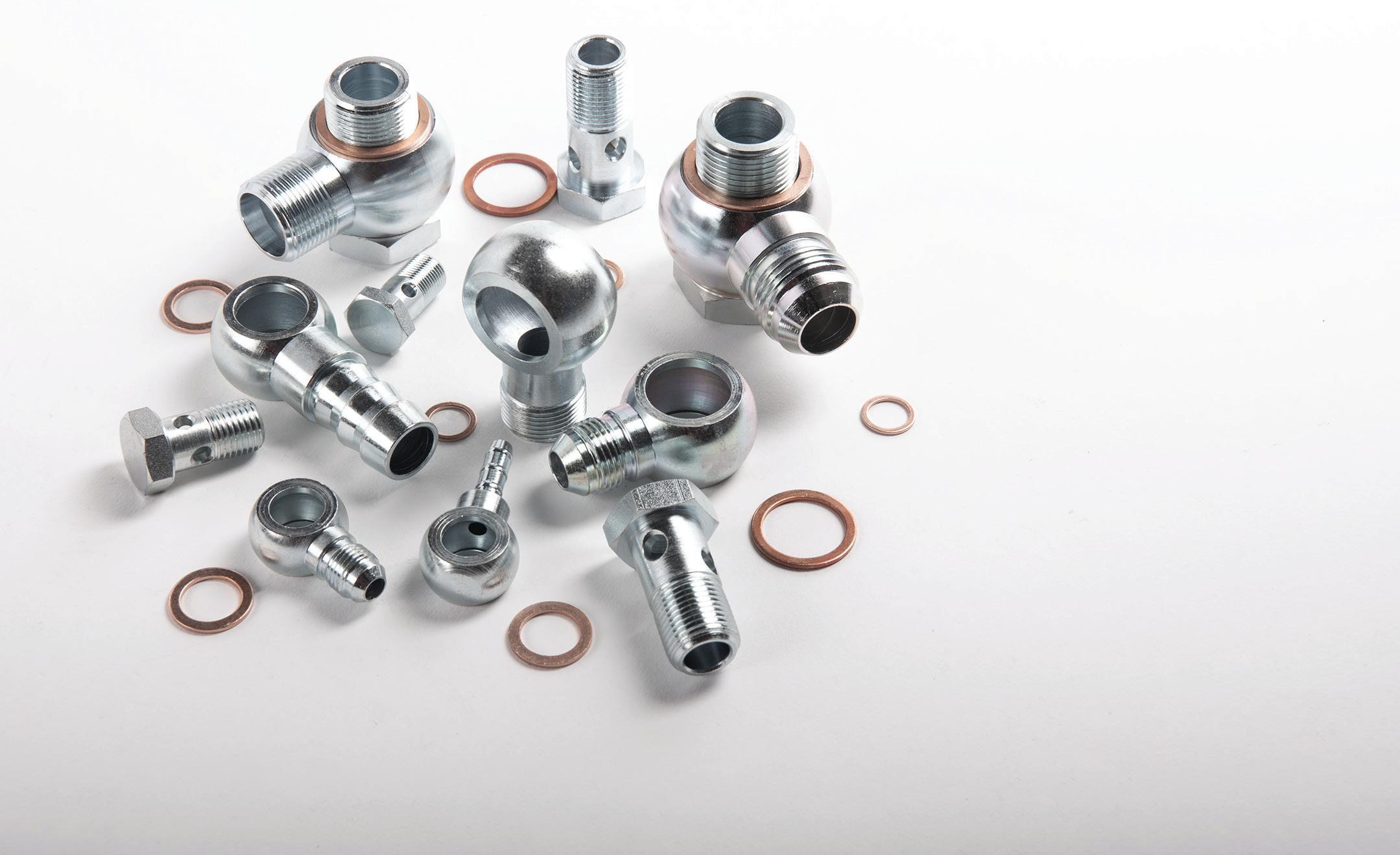
Emerson recently launched an industrial software platform that helps consumer packaged goods (CPG) and food and beverage producers better understand the health and performance of equipment and processes, improving overall plant efficiency. Movicon.NExT HMI/SCADA helps companies improve operations by identifying issues and optimizing plant management and decision-making. Modular and scalable, Movicon.NExT software goes beyond SCADA to solve automation problems, from the level of the machine to the plant overall. Movicon Pro.Lean
Image 2: Movicon.NExT HMI/SCADA is a highly modular and scalable software platform that goes well beyond SCADA and solves automation problems, improving operations, sustainability and OEE for CPGs and food and beverage producers.

provides performance data and analytics to track overall equipment effectiveness (OEE), while Movicon Pro.Energy measures and tracks energy consumption. Using visualization tools, Movicon NExT.AR makes it possible for operators to evaluate previously unreachable equipment and solve operational problems. (Image 2)

By combining the right sensors with analytics, CPGs and food and beverage producers can better understand machine energy consumption and efficiency via a multimedia monitoring solution. This solution provides leakage and consumption trending data about critical utilities, including compressed air, water, steam, gases and

PNEUMATICS
electricity, and translates it into valuable insights. Monitoring and analyzing this data is key to reaching sustainability targets, improving overall equipment effectiveness and optimizing maintenance practices. Multimedia monitoring solutions can be used with an edge analytics dashboard, which makes it possible for operators to better gauge efficiency, optimize productivity, and reduce unplanned downtime.
(Image 3)
Setting up smarter facilities that solve challenges
The opportunity for transformational results in packaging operations through the application of IIoT technology is real — but technology is an evolution, not a revolution. Merely applying more sensors and gathering more data will not solve persistent manufacturing problems.
The connected digital packaging facility can incorporate smart technology, including smart pneumatics and analytics, to enable extensive data capture of manufacturing system performance. It also leverages technologies, like edge computing and smart gateways, to simplify and speed up the delivery of that information in real time, thus
enabling deep dives into critical performance data.
The prevalence of pneumatics in facilities, paired with the advancements in smart technologies, makes pneumatic systems prime opportunities for digital transformation, energy savings and better overall equipment effectiveness. The latest pneumatic systems feature new, intelligent options for leveraging digital information to improve performance, insight, and control of manufacturing processes.
These systems feature smart sensors, digital interfaces and
Recently, Emerson helped a major consumer packaged goods company reach its ambitious sustainability goals through compressed air monitoring. The company worked with Emerson to develop a digital transformation strategy that would help it achieve net-zero carbon by 2040.
The challenge: Compressed air use in the company’s production lines was going unchecked. Without a way to measure pneumatic system airflow, leaks could release air over time while operations could use more air than they required.
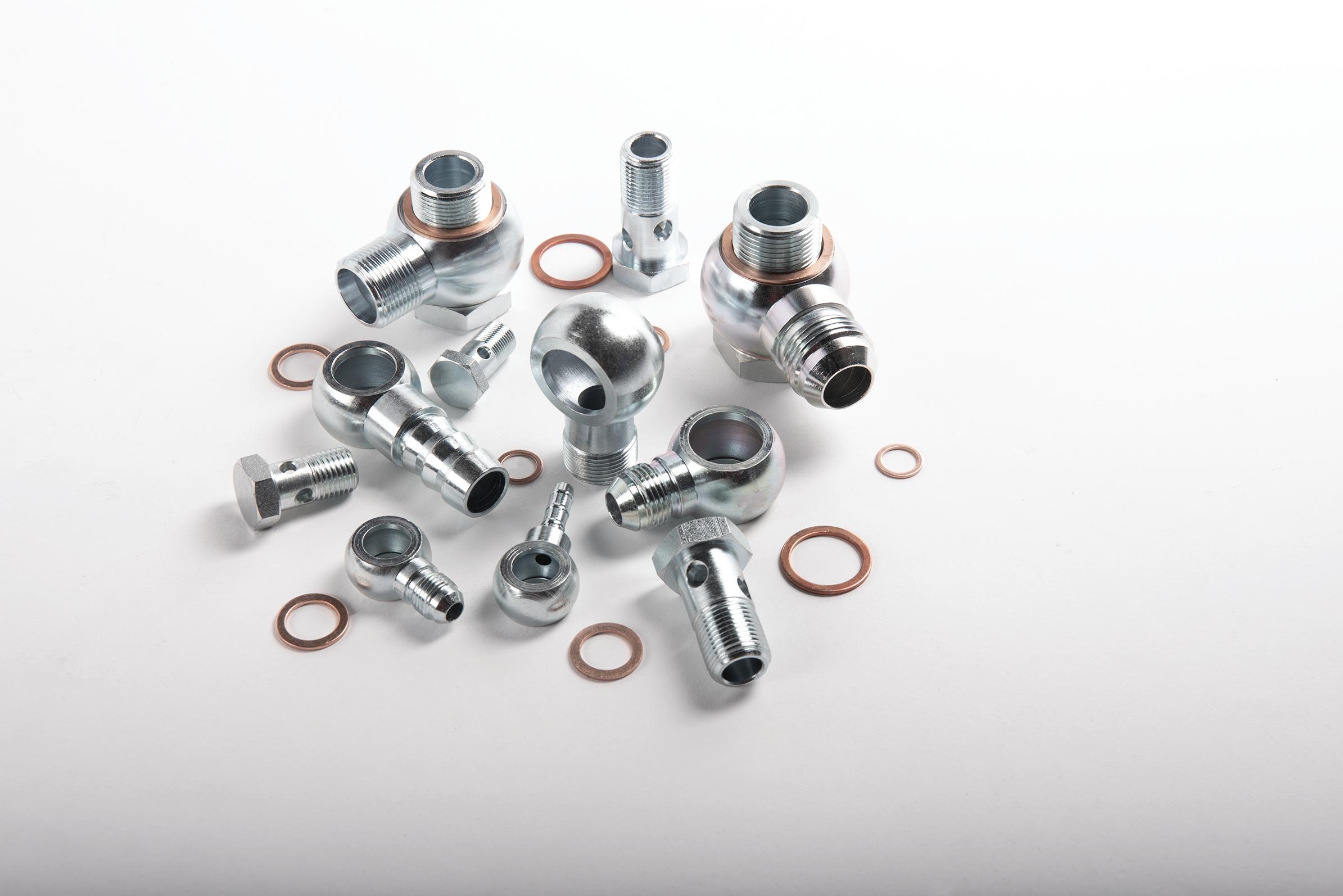
Both issues are opportunities to save compressed air and energy use.
The solution: With Emerson’s support, the company integrated real-time compressed air monitoring into one application on some of its production
Image 3: Emerson’s Multimedia Monitoring
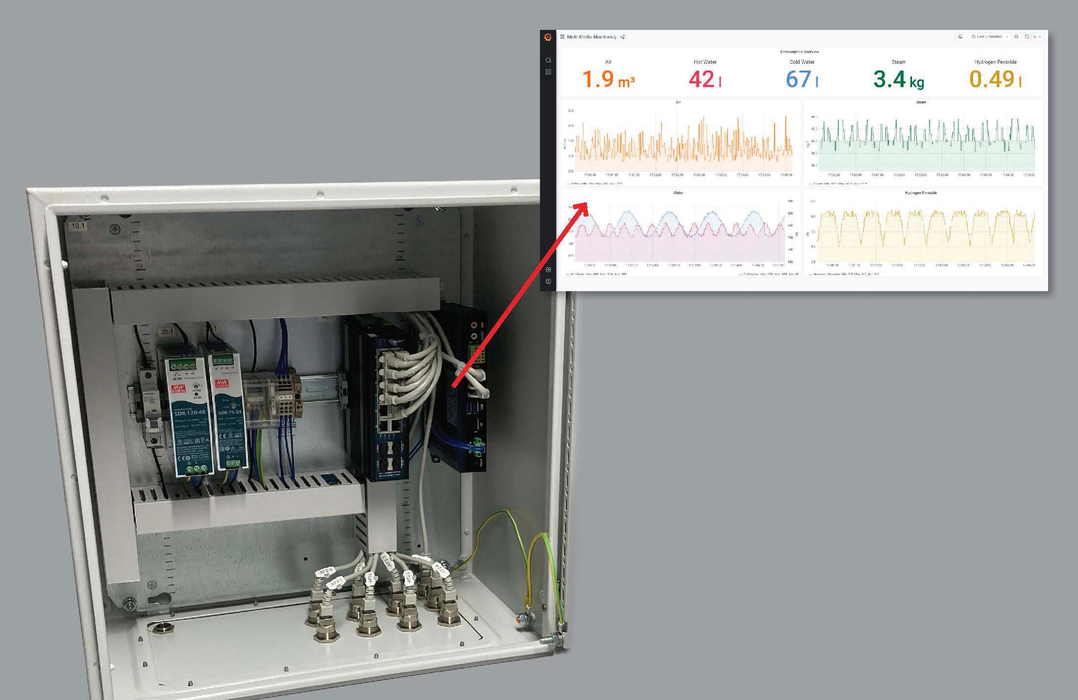
Solution provides data about compressed air, water, steam, gases, electricity and other critical utilities leakages and translates it into valuable, actionable insights.
edge-computing capabilities that provide contextualized, realtime data, enabling end-users to assess how much compressed air energy machines consume versus how much is truly needed in normal operating conditions. If the machine is using too much air, there is likely a leak that can be proactively addressed to reduce costs and CO2 emissions. The systems also allow operators to capture a more complete picture of machine health. The system can detect when valves or cylinders are due for replacement, or if they are nearing the end of their useful life,
eliminating unplanned downtime.
Remote monitoring is another example of smart technology that gathers crucial information in a more efficient manner to help plants stay up and running. There is increased interest in the use of remote troubleshooting tools to identify issues without someone having to physically be in the plant, and more smart pneumatic technologies feature these capabilities. For example, Emerson’s Aventics AF2 flow sensor and analytics package is proven to help plant operators detect compressed air leaks on
lines. The monitoring solution features Emerson’s Aventics AF2 flow sensor, the AF2’s integrated web server and an analytics dashboard.
The impact: The company has substantially reduced its compressed air waste, with machines using approximately 15% less air without sacrificing performance. Using the AF2, operators were able to better match compressed air supply and demand as well as quickly address leaks. The compressed air savings provided by the pilot monitoring solution motivated the company to integrate monitoring systems on more of its lines — from filling to packaging. To reach its sustainability goals, the company plans to continue digitally transforming its other facilities using compressed air monitoring.
www.fluidpowerworld.com 10 • 2022 FLUID POWER WORLD 47
Series AF2 flow sensor continuously monitors air consumption in large air lines and pneumatic systems. Insights provided by the AF2 high-flow model help operators detect and address leaks quickly, optimizing energy use and reducing
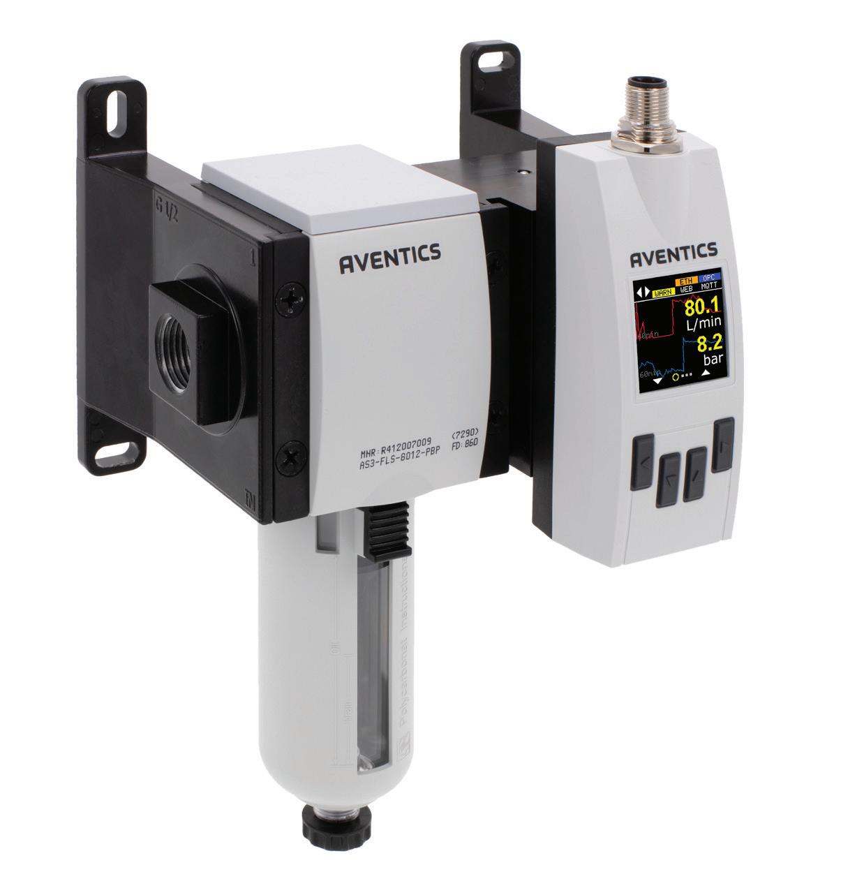

PNEUMATICS
machines, and the new high-flow model allows operators to access machine insights in larger air lines and systems. Using the AF2 high-flow model, maintenance can check for potential leaks and even be alerted when the air consumption crosses a specified threshold, all through an analytics dashboard that is accessible via smartphone, tablet or computer. (Image 4)
Analytics present the opportunity to better understand process and equipment conditions but, to be effective, requires a more complete set of data. This is achieved by deploying additional sensors on measurements not previously monitored. These pervasive sensing applications, enabled by wireless sensors and networks, help to overcome the issues of high installation cost and disruptions, enabling new, insightful data to be gained quickly and cost-effectively.
It’s important to recognize that automation technology can empower workers and elevate their productivity. However, a major challenge created by broad deployment of new technologies is the need for organizations to train and upskill workers, modify work practices and maximize the return on investment while overcoming the resistance to change from within the organization.
The application of business processes, such as lean manufacturing, six sigma and value stream mapping, can help to eliminate or minimize low-value tasks while maximizing focus on value-added activities. The organization also needs to empower stakeholders, identify sources resistant to change, and implement strategies to overcome that resistance.
New, digital-enabled technologies can make a significant difference once packaging equipment manufacturers and plant operators have a clear understanding of the problems to address. Solutions using existing infrastructure may prove less costly to implement, but change can’t come just from better or more real-time analytics: People must be empowered to make changes to processes and systems based on the direction the data tells them to go.
Connected technologies, such as intelligent devices, motion control, machine control, edge computing systems and analytics packages, establish a solid foundation and supportive tools for smart manufacturing facilities that are empowered to solve their biggest challenges quickly and effectively.
However, having the right technology isn’t enough. It’s equally important that packaging operations follow through by investing time in optimizing their overall processes around these IIoT and analytics technologies. To effectively and reliably make real-time adjustments during production, it’s essential to have a plan for how to use new data streams and analytics to make confident long-term decisions. Purchasing new equipment, entering new markets and using new types of packaging can feel like less of a risk when backed by real data. This is the goal — and ultimate benefit — that the power of analytics and digital transformation can offer. FPW
Emerson | emerson.com48 FLUID POWER WORLD 10 • 2022


Industries Served: • Oil & Gas • Industrial Hydraulics • Mining • Forestry • Chemical & General Processing Plants • Medical • Aerospace • Factories • Mobile Equipment • Defense • Machine Tool • Testing Equipment • Ocean Depth Technology • Automotive • Food Processing • Agriculture • Industrial • Aviation • Petrochemical • Marine • Subsea DELAWARE MANUFACTURING INDUSTRIES CORPORATION Solutions Under Pressure ISO 9001 Certified Check Valves Bar & Custom Manifolds Medium - High Pressure Valves Low Pressure Suction Valves Flow Control Needle Valves SAE Port Flanges Subsea & Gas Valves Specialty Valves SSW Power Unit System 800.248.DMIC (3642) • WWW.DMIC.COM • SALES@DMIC.COM Made In America Tank Accessories Ball Valves Check Valves Flow Control Valves Needle Valves Flanges & Adapters Bar & Custom Manifolds Pressure Gauges & Snubbers SSW Power Unit Systems Transfer Pumps
Straight plastic caps
Common cartridge valve cavities
MOCAP has expanded its offerings of its S series straight plastic caps. These caps are suitable for use as shipping caps, end caps, pipe caps, product protection, paint protection and thread protection. These S series caps are available with a plain top, and many of the sizes are also available with a knurled top-collar, which makes them easy-to-grip and remove. In addition, the caps are also available in both LDPE plastic and flexible TPE. Now available in nearly 200 total metric and imperial sizes to fit 0.078 to 5.250 in. (2 to 133.35 mm) outside diameters.


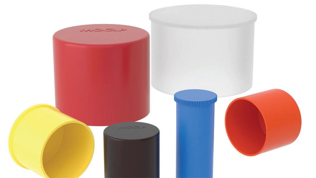
Miniature back pressure regulator
The Type 855BP miniature back pressure regulator is a compact relief valve that provides economical, high performance pressure relief with an adjustable set point. It is a normally closed valve that will remain closed until the inlet pressure exceeds the regulator’s set point. The Type 855BP is capable of relieving at a rate up to 35 scfm (990 Nl/min) and is available in ¼ in. NPT porting. The Type 855BP will handle a 250 psi (17.5 bar) maximum system pressure and offers five setpoint pressure ranges from 0-5 psi (0-0.4 bar), up to 0-100 psi (0-7 bar). The Push-Pull locking knob feature prevents inadvertent pressure adjustment.
For optimized interchangeability for 3,000 psi systems, Common cavity cartridge valves are a suitable drop-in solution. They use the SAE style cavity, so are compliant to industry standards. The Sun Common Cartridge Valve Family Includes:

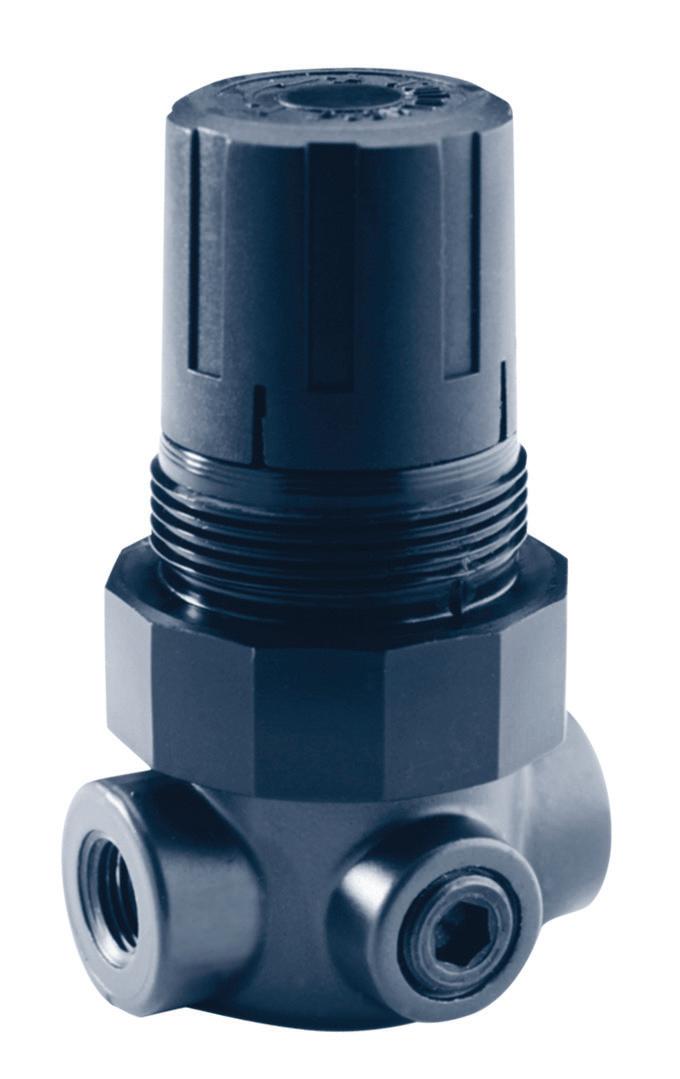
• DNUC and DNTC 4-way, 3-position, solenoid valves, direct acting, directional spool valves, for outrigger controls, scissor lifts, municipal trucks, and aerial platforms.
• DNUT 4-way, 2-position solenoid-operated, direct acting, balanced spool directional valve, for tractors, bull dozers, and applications requiring pilot control.
• DMUT and DMUQ 3-way, 2-positions solenoid-operated, direct acting, balanced spool directional valves.
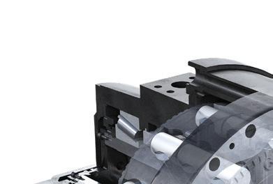
• DLUT 2-way, 2-position solenoid-operated, direct acting, balanced spool directional valve, for sweepers or industrial hydraulic machines with max pressures less than 3,000 psi.
• CSTT single ball, shuttle valve, and CXUT free-flow, nose-toside check valve.

Hydraulic direct drives

S-series hydraulic direct drives produce continuous high power efficiently without gears. They now come with displacements from 4,400 to 22,500 ccm and direct mount valves. S-series motor has robust piston design and no backlash, delivering a constant torque from low to high speeds. They are suitable for demanding applications with direction changes and shock loads. Their 2-speed function means rotation speed can be changed on-the-go without stopping the operation.

50 FLUID POWER WORLD 10 • 2022 www.fluidpowerworld.com PRODUCT WORLD
ISO 5599/1 pneumatic solenoid valves
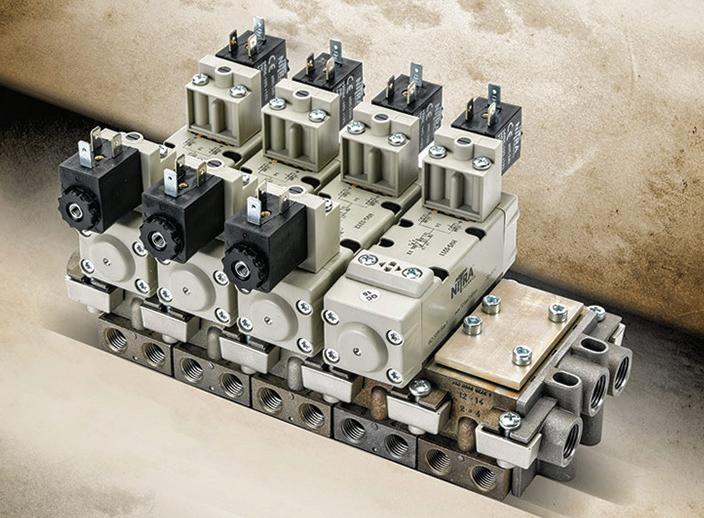
AutomationDirect automationdirect.com
The NITRA ISO 5599/1 pneumatic solenoid valve components are completely interchangeable with any brand of ISO 5599/1 equipment. ISO 5599 size one and size two components include solenoid valve bodies in 5-way, 2-position configurations with single or double solenoids and 5-way, 3-position, double solenoid valves with a center-pressure, center-closed, or center-exhaust configuration. Stand-alone bases and manifold components with a side or bottom orientation and NPT or G-thread ports are also offered. Solenoid coils are available in 12 and 24 Vdc, 24, 110 and 220 Vac. Accessories include manifold blanking plates, inlets, blind ends, and seal kits.
Ergonomic joystick designed for comfort

Sure Grip Controls suregripcontrols.com
Endurance Series ergonomic joystick for heavy-duty, off-highway vehicle applications is available in right-hand and left-hand options. It features advanced features that provide maximum operator comfort and efficiency in a durable IP69K sealed enclosure. Designed to match an operator’s natural hand position with height and width consideration, it allows for easier control of faceplate components and reduced user fatigue. The joystick’s dual-angle faceplate allows for the operation of up to three rows of controls without reaching or straining. The triangular faceplate configuration maximizes efficiency with the buttons and modules in an arc that matches an operator’s natural thumb movement. The design is fully modular and customizable, allowing customers to select faceplate controls that work best for their application.
The joystick is fully sealed to IP69K and impact resistant. Rated for operation at –40° to 185° F (–40° to 85° C), the CE-certified, Sil2 compatible joystick is rated for up to 5 million cycles or 20 million operations.
PowerBox for vehicle electrification
Hawe Hydraulik hawe.com
The PowerBox for mobile machine electrification is easy to install and operate. In addition to the battery packs, it contains a new motor pump unit (MPU), power distribution unit (PDU), a charger, and the hydraulics. It can be adapted to the specific requirements of the vehicle manufacturer, right down to the disassembled assembly, which can be integrated directly into the vehicle. Connected and fully charged, the PowerBox is ready for autonomous use, and commissioning is accomplished quickly.
The included plug-in system for the battery packs significantly simplifies runtime management of the electrically powered vehicle or working hydraulics. When the battery pack charge is exhausted, it can simply be pulled out and replaced with charged spare batteries. The battery packs can also be charged flexibly at convenient times in the company’s own plant or on-site.
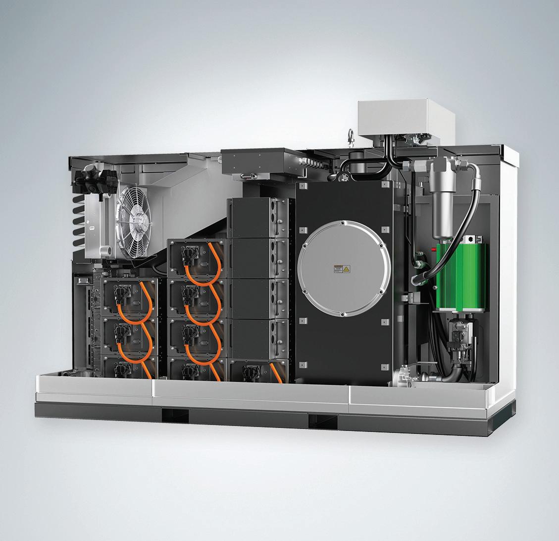
www.fluidpowerworld.com 10 • 2022 FLUID POWER WORLD 51
Servo cartridge valves


The X700 series servo cartridge valves serve as robust throttle valves in electrohydraulic flow control systems, especially those requiring quick dynamic responses and high flows. Typical applications include die-casting, metal sheet forming, presses, and other heavy industrial equipment. The valves’ flow-optimized design delivers a huge leap in flow performance compared to alternative products, and their robust design enables a maximum main stage operating pressure of 420 bar (6,000 psi). For maximum flexibility, customers can choose between three interface options – analog, fieldbus or both combined in the same valve –to be prepared for IoT requirements. Three sizes according to ISO 7368 are available: size 32 (X702), size 40 (X703), and size 50 (X704). All valves are equipped with integrated electronics and closed-loop position control for the main stage cartridge poppet.

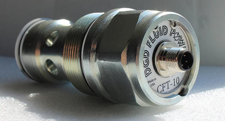
CFT flow meters


The next-generation of CFT flow meters have upgraded electronics and will give greatly improved response times. Also included are features that raise the operating temperature to approximately 250° F and the onboard option for field adjustability include outputs of either 0.5-4.5 V or 1-10 V. There are also eight distinct flow ranges to choose from: 0-10 gpm through 0-125 gpm. Additionally, a rotary selector switch with 16 different set points is available with this new generation. The cavity fit is continuing to be Sun’s T-18A.

52 FLUID POWER WORLD 10 • 2022 www.fluidpowerworld.com PRODUCT WORLD CFCINDUSTRIALTRAINING.com 7042 Fairfield Business Drive Fairfield, Ohio 45014 +1 513.874.3225 info@cfcindustrialtraining.com UPSKILL YOUR WORKFORCE! ONSITE AND CERTIFICATION FOR: TRAINING CFC provides direct, Industry and/or Machine specific training to companies the world over. Electrical Techs & Engineers Hydraulic Techs & Engineers Pneumatic Techs & Engineers Our Hands On Training Equipment is mobilized directly to your facility with Certified Instructors traveling on site. This turnkey approach includes all books, materials, equipment, and travel arrangements. We have the capability to upskill your entire workforce NOW! Multicraft Techs & Engineers
SEARCH MILLIONS OF PARTS FROM THOUSANDS OF SUPPLIERS

PRICING & AVAILABILITY
Get real-time pricing and stock info from authorized distributors and manufacturers.

ABOUT DESIGNFAST

HOW DOES IT WORK?
DATA SHEETS & SPECS
View and download product data sheets and technical speci cations.
SOURCE & PURCHASE
Compare options from suppliers and buy direct from distributors and manufacturers.

DesignFast is a search engine for nding engineering components and products. With DesignFast, engineers and sourcing professionals can quickly search for products, compare prices, check stock, view data sheets and go direct to the supplier for purchase.

DesignFast aggregates product data from thousands of suppliers and distributors and makes it available for searching. DesignFast provides pricing, availability and product data sheets for free download.

designfast.com
HIGH EFFICIENCY, BEST PERFORMANCE

Tank mounted return filter. Working pressure up to 116 psi, flow rates up to 237 gpm.
FMM 050-150


In-line high pressure filter. Working pressure up to 6,090 psi, flow rates up to 79 gpm.
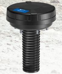

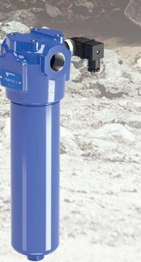
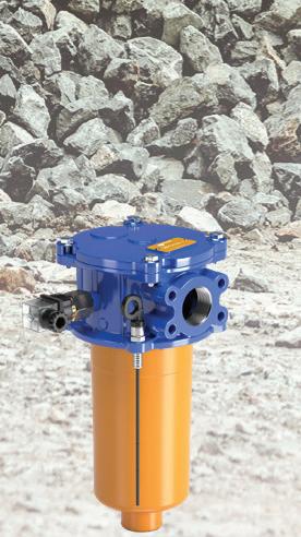


TAP 114
Filling caps and air breathers with 10 µm filter element. Flow rate up to 422 gpm. Replaceable filter element.

LVA

Visual oil level indicators available in three sizes, to monitor the level of flow in the tank: range with wheelbase up to 10 in.


PASSION TO PERFORM
529-1300

www.mpfiltriusa.com (215)
sales@mpfiltriusa.com
COMPONENT FOCUS
By Josh Cosford • Contributing EditorDetecting cylinder linear transducers stroke and position with
If you have a high-performance motion control application, the chances are good you have a linear position sensor on your hydraulic cylinder. These are sometimes called LVDTs or LVTs [Linear Variable (Differential) Transformers], but these linear transducers can accurately sense piston and stroke positions or distance, especially when high accuracy is needed. A magnet is permanently attached to the piston, and a probe is inserted inside the hollow piston/rod assembly. They can be a simple hall effect or advanced design like MTS’ Temposonic, which is highly accurate. As the cylinder strokes, the magnetic field is picked up by the transducer, relaying the signal back to the PLC.
For industrial applications, the hardware, which includes the onboard electronics, will often protrude from the cap end of the cylinder. This configuration makes clevis mount cylinders difficult, so switching to a rear trunnion would be a better option. Electronic output can vary vastly, and can literally be any signal usable by today’s controllers; variable amperage, variable voltage, PWM, or even any of the many CAN protocols. Mobile applications aren’t so free with cap end space, and are nearly always clevis or swivel rod eye mounts, so the linear transducers are compact enough to be integrally mounted in the cylinder, although they are often less sophisticated.
Linear transducers work using a principle called magnetostriction. A typical transducer uses three major components; the sensor assembly, a waveguide, and a permanent magnet. The sensor assembly houses the control electronics and is responsible for sending and receiving the signal, then transmitting that signal to the PLC. The waveguide is the probe extending the length of the transducer, which emits and senses the magnetic field. Finally, the permanent magnet attaches to the traveling component the transducer measures.
The sensor assembly emits a current pulse that travels the length of the waveguide, emitting a magnetic field around the length of the probe. As the pulse passes through the field of the permanent magnet, the interaction creates a strain pulse that travels back down the length of the waveguide until the sensor assembly senses it.

The difference between the sent and received signal allows the sensing unit to precisely identify the distance of the permanent magnet along the length of the waveguide. Many designs are accurate to within hundredths of an inch or better.
Output configurations include, but are not limited to, 0-10 V, 4-20 mA, and CANBUS of various standards. When installed inside a hydraulic cylinder, the rod must be gun-drilled to allow space for the probe, and the magnet gets bolted to the piston’s back.
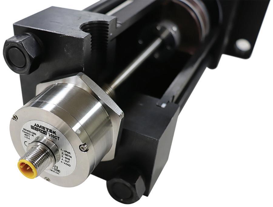
A port boss must be welded or machined into the “position 5” of the cylinder cap (its back end), where the transducer may be screwed tight upon installation. Some hydraulic cylinder mounts prevent the back end installation, such as with ME6 or MX1 mounts, and any clevis or rear pivot type cylinders. Rear mount cylinders will take advantage of internally mounted sensor assemblies which employ a connector assembly mounted to one of the available cap side surfaces.
Linear transducers may also operate outside of a linear actuator altogether. Stand-alone LDTs may be mounted beside or atop any actuator, where the rod end of the cylinder attaches to the mounting hardware at the end of the sensor. A bar or rod attaches the two, and the transducer is along for the ride to accurately measure linear displacement.
www.fluidpowerworld.com 10 • 2022 FLUID POWER WORLD 55
FPW
Gemcos CT959 linear position sensor housing for hydraulic cylinder.
Statement
9/29/2022
7 $125.00/year
WTWH Media, LLC 1111 Superior Ave., Suite 2600, Cleveland, OH 44114
WTWH Media, LLC 1111 Superior Ave., Suite 2600, Cleveland, OH 44114
Mike Emich; WTWH Media, LLC 1111 Superior Ave. Suite 2600, Cleveland, OH 44114
Paul J. Heney; WTWH Media, LLC 1111 Superior Ave., Suite 2600, Cleveland, OH 44114
Mary Gannon; WTWH Media, LLC 1111 Superior Ave., Suite 2600, Cleveland, OH 44114
Bruce A. Sprague (888) 543-2447
WTWH Media, LLC 1111 Superior Ave., Suite 2600, Cleveland, OH 44114
Scott McCafferty 1111 Superior Ave., Suite 2600, Cleveland, OH 44114
Mike Emich 1111 Superior Ave., Suite 2600, Cleveland, OH 44114
Marshall Matheson 1111 Superior Ave., Suite 2600, Cleveland, OH 44114
Winco,
Swivels
LEADERSHIP TEAM
Co-Founder, VP Sales Mike Emich 508.446.1823
@wtwh_memic
FOLLOW US ON
the
team on twitter
Co-Founder, Managing Partner Scott McCa erty 310.279.3844
EVP
Matheson
56 FLUID POWER WORLD 10 • 2022 www.fluidpowerworld.com
of Ownership,Management,andCirculation (Requester Publications Only) 1. Publication Title 2. Publication Number 3. Filing Date 4. Issue Frequency 5. Number of Issues Published Annually6. Annual Subscription Price (if any) 8. Complete Mailing Address of Headquarters or General Business Office of Publisher (Not printer) 9. Full Names and Complete Mailing Addresses of Publisher, Editor, and Managing Editor (Do not leave blank) Publisher (Name and complete mailing address) Editor (Name and complete mailing address) Managing Editor (Name and complete mailing address) 10.Owner (Do not leave blank. If the publication is owned by a corporation, give the name and address of the corporation immediately followed by the names and addresses of all stockholdersowningor holding 1 percent or more of the total amount of stock. If not owned by a corporation, give the names and addresses of the individual owners. If owned by a partnership or other unincorporated firm, give its name and address as well as those of each individual owner. If the publication is published by a nonprofit organization, give its name and address.) 11.Known Bondholders, Mortgagees, and Other Security Holders Owning or Holding 1 Percent or More of Total Amount of Bonds, Mortgages, or Other Securities. If none, check box PS Form 3526-R September 2007 (Page 1 of 3 (Instructions Page 3)) PSN: 7530-09-000-8855 PRIVACY NOTICE: See our privacy policy on www.usps.com None 7. Complete Mailing Address of Known Office of Publication (Not printer)(Street, city, county, state, and ZIP+4® Contact Person Telephone (Include area code) Full Name Complete Mailing Address Complete Mailing AddressFull Name 12. Tax Status (For completion by nonprofit organizations authorized to mail at nonprofit rates)(Check one) Has Not Changed During Preceding 12 Months Has Changed During Preceding 12 Months (Publisher must submit explanation of change with this statement) The purpose, function, and nonprofit status of this organization and the exempt status for federal income tax purposes: PS Form 3526-R, September 2007 (Page 2 of 3) Extent and Nature of Circulation Average No. Copies Each Issue During Preceding 12 Months No. Copies of Single Issue Published Nearest to Filing Date a. Total Number of Copies (Net press run) c. Total Paid and/or Requested Circulation (Sum of 15b (1), (2), (3), and (4)) In-County Paid/Requested Mail Subscriptions stated on PS Form 3541. (Include direct written request from recipient, telemarketing and Internet requests from recipient, paid subscriptions including nominal rate subscriptions, employer requests, advertiser’s proof copies, and exchange copies.) d.Nonrequested Distribution (By Mail and Outside the Mail) Total Distribution (Sum of 15c and e) 17. Signature and Title of Editor, Publisher, Business Manager, or Owner 13. Publication Title 15. Percent Paid and/or Requested Circulation (15c divided by times 100) Date Nonrequested Copies Distributed Outside the Mail (Include Pickup Stands, Trade Shows, Showrooms and Other Sources) Total (Sum of 15f and g) 14. Issue Date for Circulation Data Below 16. Publication of Statement of Ownership for a Requester Publication is required and will be printed in the issue of this publication. b. Legitimate Paid and/or Requested Distribution (By Mail and Outside the Mail) Copies not Distributed (See Instructions to Publishers #4, (page #3)) Outside County Paid/Requested Mail Subscriptions stated on PS Form 3541. (Include direct written request from recipient, telemarketing and Internet request s from recipient, paid subscriptions including nominal rate subscriptions, employer requests, advertiser’s proof copies, and exchange copies.) (1) (2) (4) Requested Copies Distributed by Other Mail Classes Through the USPS (e.g. First-Class Mail® Sales Through Dealers and Carriers, Street Vendors, Counter Sales, and Other Paid or Requested Distribution Outside USPS®(3) (1) (3) (2) (4) Outside County Nonrequested Copies Stated on PS Form 3541 (include Sample copies, Requests Over 3 years old, Requests induced by a Premium, Bulk Sales and Requests including Association Requests, Names obtained from Business Directories, Lists, and other sources) In-County Nonrequested Copies Stated on PS Form 3541 (include Sample copies, Requests Over 3 years old, Requests induced by a Premium, Bulk Sales and Requests including Association Requests, Names obtained from Business Directories, Lists, and other sources) Nonrequested Copies Distributed Through the USPS by Other Classes of Mail (e.g. First-Class Mail, Nonrequestor Copies mailed in excess of 10% Limit mailed at Standard Mail® or Package Services Rates) Total Nonrequested Distribution (Sum of 15d (1), (2), (3) and (4)) f. e. g. h. i. I certify that all information furnished on this form is true and complete. understand that anyone who furnishes false or misleading information on this form or who omits material or information requested on the form may be subject to criminal sanctions (including fines and imprisonment)and/or civil sanctions (including civil penalties). Fluid Power World
� N/A Fluid Power World August 2022 Owner (If the publication is owned by a corporation, give the name and address of the corporation immediately followed by the names and addresses of all stockholders owning or holding 1 percent or more of the total amount of stock. If not owned by a corporation, give names and addresses of the individual owners. If owned by a partnership or other unincorporated firm, give its name and address as well as those of each individual owner. If the publication is published by a nonprofi organization, give its name and address): PS Form 3526-R July 2014 16. X certify that 50% of all my distributed copies (electronic and print) are legitimate requests or paid copies. PS Form 3526-R, September 2007 (Page 2 of 3) Extent and Nature of Circulation Average No. Copies Each Issue During Preceding 12 Months No. Copies of Single Issue Published Nearest to Filing Date a. Total Number of Copies (Net press run) c. Total Paid and/or Requested Circulation (Sum of 15b (1), (2), (3), and (4)) In-County Paid/Requested Mail Subscriptions stated on PS Form 3541. (Include direct written request from recipient, telemarketing and Internet requests from recipient, paid subscriptions including nominal rate subscriptions, employer requests, advertiser’s proof copies, and exchange copies.) d.Nonrequested Distribution (By Mail and Outside the Mail) Total Distribution (Sum of 15c and e) 17. Signature and Title of Editor, Publisher, Business Manager, or Owner 13. Publication Title 15. Percent Paid and/or Requested Circulation (15c divided by times 100) Date Nonrequested Copies Distributed Outside the Mail (Include Pickup Stands, Trade Shows, Showrooms and Other Sources) Total (Sum of 15f and g) 14. Issue Date for Circulation Data Below 16. Publication of Statement of Ownership for a Requester Publication is required and will be printed in the issue of this publication. b. Legitimate Paid and/or Requested Distribution (By Mail and Outside the Mail) Copies not Distributed (See Instructions to Publishers #4, (page #3)) Outside County Paid/Requested Mail Subscriptions stated on PS Form 3541. (Include direct written request from recipient, telemarketing and Internet request s from recipient, paid subscriptions including nominal rate subscriptions, employer requests, advertiser’s proof copies, and exchange copies.) (1) (2) (4) Requested Copies Distributed by Other Mail Classes Through the USPS (e.g. First-Class Mail® Sales Through Dealers and Carriers, Street Vendors, Counter Sales, and Other Paid or Requested Distribution Outside USPS®(3) (1) (3) (2) (4) Outside County Nonrequested Copies Stated on PS Form 3541 (include Sample copies, Requests Over 3 years old, Requests induced by a Premium, Bulk Sales and Requests including Association Requests, Names obtained from Business Directories, Lists, and other sources) In-County Nonrequested Copies Stated on PS Form 3541 (include Sample copies, Requests Over 3 years old, Requests induced by a Premium, Bulk Sales and Requests including Association Requests, Names obtained from Business Directories, Lists, and other sources) Nonrequested Copies Distributed Through the USPS by Other Classes of Mail (e.g. First-Class Mail, Nonrequestor Copies mailed in excess of 10% Limit mailed at Standard Mail® or Package Services Rates) Total Nonrequested Distribution (Sum of 15d (1), (2), (3) and (4)) f. e. g. h. i. certify that all information furnished on this form is true and complete. understand that anyone who furnishes false or misleading information on this form or who omits material or information requested on the form may be subject to criminal sanctions (including fines and imprisonment)and/or civil sanctions (including civil penalties). [ page 1 of 4 (see instructions page 4) ] PSN: 7530-09-000-8855 PRIVACY NOTICE: See our privacy policy on www.usps.com 78.1% 94.4% 0 0 0 0 0 0 2,046 234 0 0 0 0 10,912 10,341 8,518 9,755 8,518 9,755 2,384 575 10,902 10,330 10 11 10,912 10,341 338 341 October 2022 9/22/2022 Electronic Copy Circulation a. Requested and Paid Electronic Copies b. Total Requested and Paid Print Copies (15c) + Requested/Paid Electronic copies (16a) c. Total Requested Copy distribution (15f) + Requested/Paid Electronic copies (16a) d. Percent Paid and/or Requested Circulation (Both print & electronic copies (16b divided By 16c x 100) 0 8,518 10,902 78.1% 0 9,755 10,330 94.4% 17. 18. PS Form 3526-R, July 2014 (page 2 of 4) Pat Curran, Senior Digital Media Manager 0 1 8 - 0 6 0 Seven issues/year: February; April; June; July; August; October; December Adaptall ...................................... 46 AutomationDirect ............. 1, Insert Camozzi Automation 3 Canfield Connector 48 CFC Industrial Training 52 Clippard BC Compact Automation Products 25 Coxreels ...................................... 22 DMIC .......................................... 49 FluiDyne Fluid Power 5 HydraForce 13 Hydraulex Global 19 IFPE (AEM) 27 Industry Summit 7 J.W.
Inc. .......................... 37 Main Mfg ...................................... 8 Motion 43 MP Filtri USA 54 OFCO (Ohio Fabricators) 15 Panolin America 11 Permco Cover, IBC Rota Engineering ........................ 21 SIKO .............................................. 2 Super
42 Tompkins Industries IFC, 8 Veljan Hydrair 9 Yuken 29 Zero-Max, Inc. 34
memich@wtwhmedia.com
smccafferty@wtwhmedia.com @SMMcCafferty
Marshall
805.895.3609 mmatheson@wtwhmedia.com @mmatheson Follow
whole
@FluidPowerWorld
AD INDEX


Home of the American Champ 1500 Frost Road Streetsboro, OH 44241 PERMCO MVP The Permco MVP is the only pump that fits all 5 manufacturers of Allison Brand Transmissions. It takes an MVP to get the job done. Contact us today. permco.com | 800.626.2801MVP Designed to be used in Heavy & Medium Duty Trucks & Trailers. Pump and cylinder protected in the “Raise” and “Neutral” position of the spool. It takes an MVP to get the job done. Saves you money. Saves you time. Saves you hassle.
Precision Control Solutions

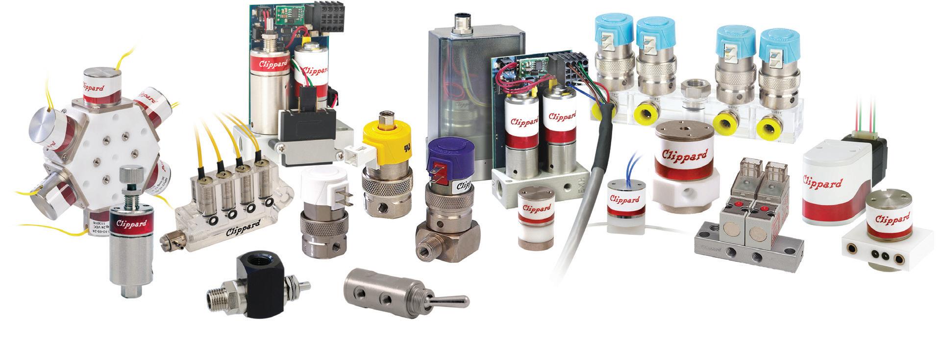


Designing efficient systems involves much more than simply understanding a few basic principles. There is a true art to balancing the specific requirements of an application in order to achieve the desired goals in the best possible way. Help us understand the unique needs of your application and together, we’ll develop something that surpasses what any of us could have done alone.
Contact your distributor to learn more, or visit clippard.com to request a free catalog and capabilities brochure.

877-245-6247 CINCINNATI • BRUSSELS • SHANGHAI • Electronic Valves • Proportional Valves • Isolation Valves • Precision Regulators • Toggle & Stem Valves • Needle Valves • Electronic Pressure Controllers • Pneumatic Assemblies • Special Manifold Designs • Pneumatic Circuit Design • Cylinders • Fittings, Hose & Tubing