motion control handbook
DESIGNWORLDONLINE.COM MOTIONCONTROLTIPS.COM AUGUST 2023
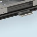
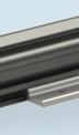
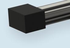
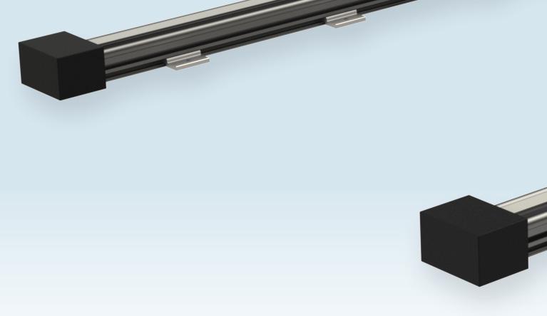
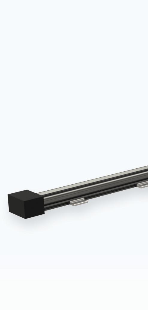
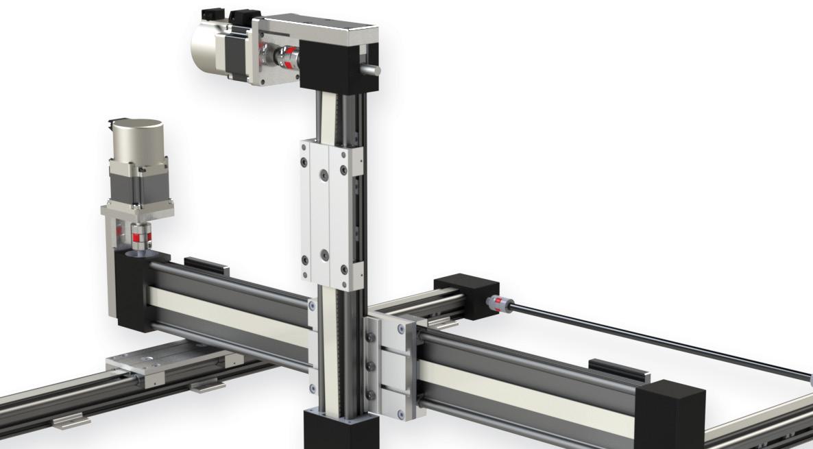
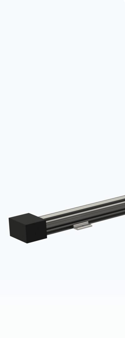
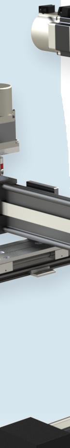
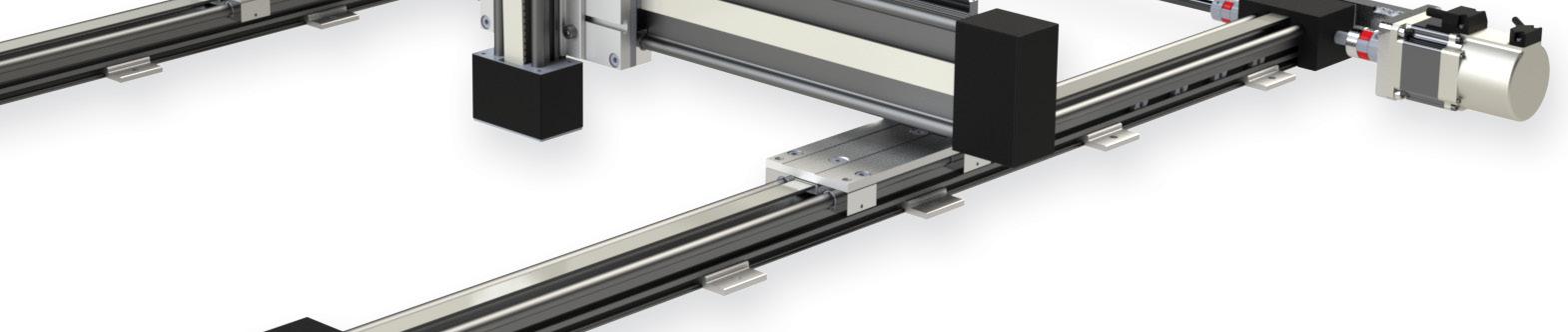
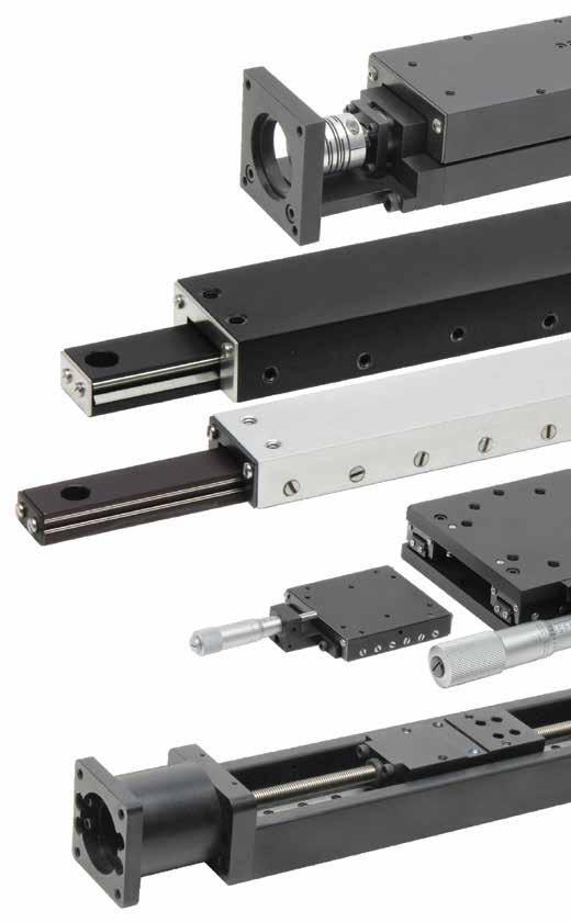
Linear Motion Actuators


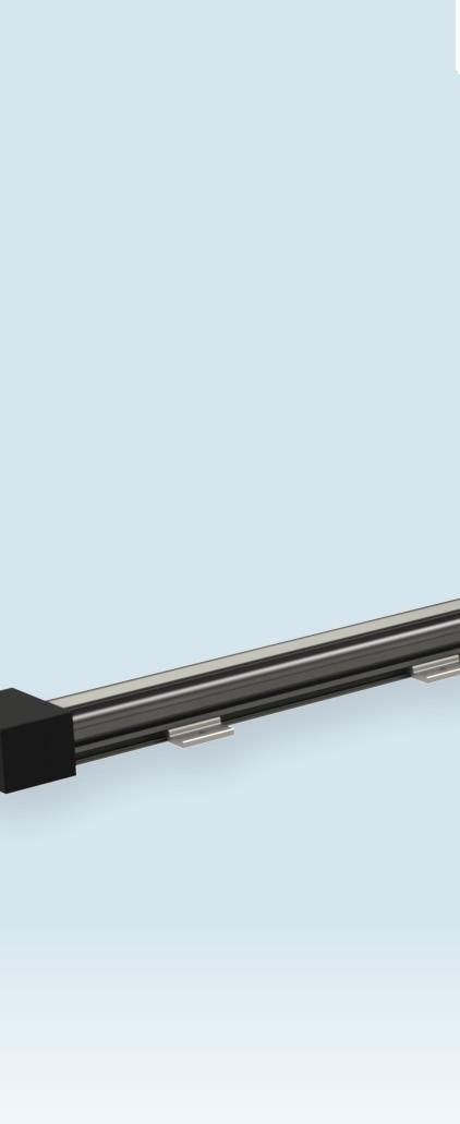


Starting at $355.00 (SAW1040-05-B)


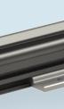
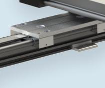
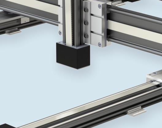
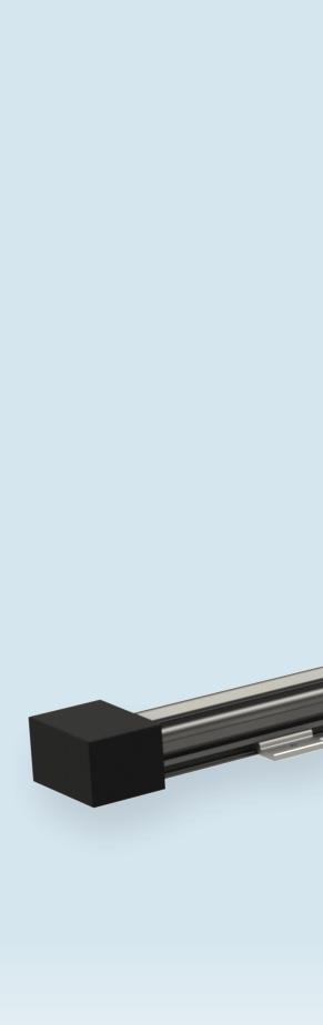
igus XYZ gantries offer an economical solution for creating a motion system with up to 3 axes of motion. These systems are available with belt driven or lead screw driven slides. They are easy to assemble, are stackable, and can be used as a single axis, double axis, dual drive axis, or as a complete 3-axis XYZ system.
Features:


• Maintenance and lubrication free


• 14 belt driven actuators from 200mm travel length to 1000mm travel length


• 13 lead screw driven actuators from 100mm travel length to 750mm travel length
• Rails made from durable 6061-T6 aluminum with hard anodized finish


• Motor mounts for SureServo and SureStep motors


• T-slots in rails allow switches and sensors to be easily installed


the #1 value in automation Order Today, Ships Fast! * See our Web site for details and restrictions. © Copyright 2022 AutomationDirect, Cumming, GA USA. All rights reserved. 1-800-633-0405 Gantry Components for Less Rugged industrial actuators & slides for demanding 24/7 applications Research, price, buy at: www.automationdirect.com/linear-motion
Available Precision Gearboxes (for Stepper & Servo) Stepper Systems SureServo2 Servo Systems
Also
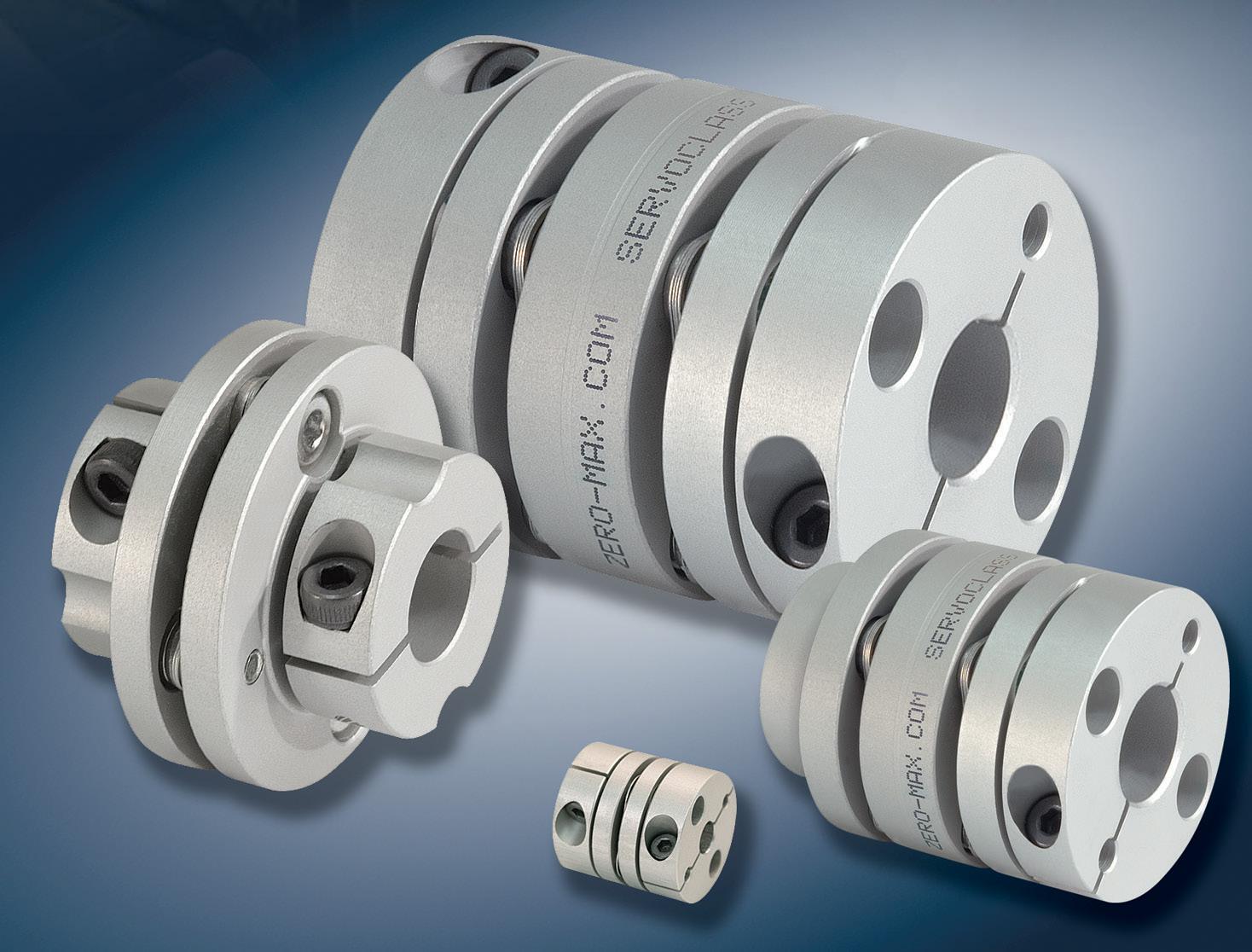
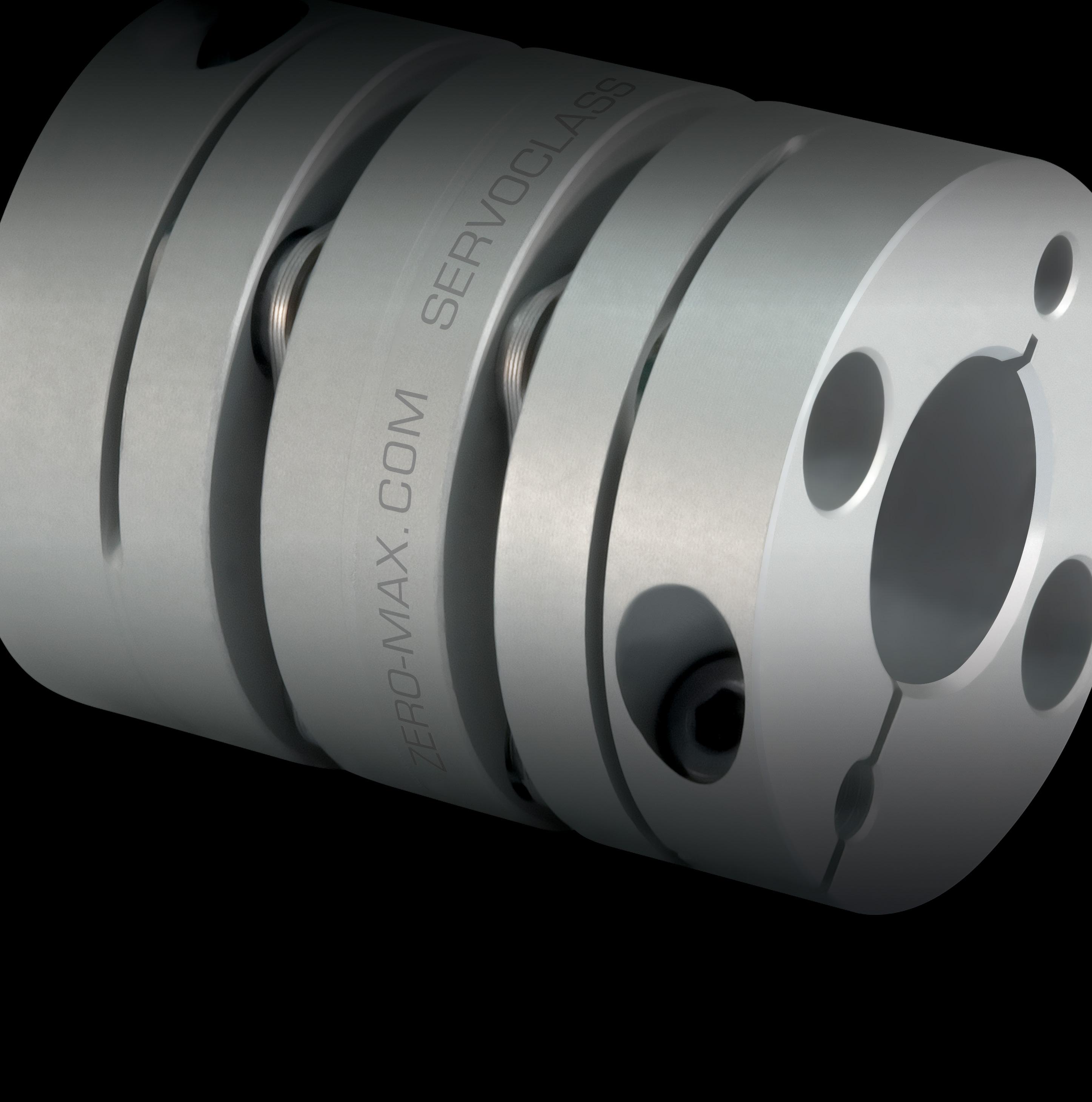
•Engineering Assistance / Fast Delivery www.zero-max.com 800.533.1731 PRECISE. ROBUST.AVAILABLE.


05 E DITORIAL 06 STAFF 08 L INEAR MOTION 18 CONTROLLERS 24 BELTS & PULLEYS 30 CABLES & CONNECTIVITY 38 CONVEYORS 42 COUPLINGS 46 SERVOGEARS & GEARMOTORS 62 ENCODERS & FEEDBACK 67 SYSTEM DESIGN 74 SHOCK & VIBRATION MITIGATION 79 AD INDEX 80 WINDUP CONTENTS 62 08 volume 9 number 3 4 DESIGN WORLD — MOTION 8 • 2023 motioncontroltips.com | designworldonline.com 42
THE BORING TRUTH ABOUT AI
You can't turn anywhere today without hearing about artificial intelligence or AI Most AI coverage seems to exist on a kind of truncated spectrum with two dominant endpoints.
On the one end is absolute AI triumphalism and cheerleading — as in “AI will solve X” with X being any and every social ill and problem that humanity faces and will ever face. In other words, something like the snake oil of the 21st century.
At the other end is the doomsaying of how artificial general intelligence or so-called superintelligent AI will wipe out humanity and end human civilization. Keep in mind that no such thing as general AI even exists, and many experts doubt whether such a thing is even possible. Cautious realists think that even if such a thing came into being, we’re probably a long way off from seeing it realized in any meaningful way.
In between these two extremes is to be found the sensible (or boring) middle. This is the simple truth that AI has been used in many different applications for many years, perhaps in places that people don’t even know about or realize. For instance, personal assistants like Siri, Alexa and Google Assistant have been powered by AI for years.
A broad, workable definition of AI is that it is software that is designed to do a particular task extremely well. Here is the distinction between this type of AI (often called narrow AI) and other types such as general AI. In this sense, AI is not so much a major disruption as another step on the evolutionary path to using software and algorithms to better optimize all kinds of engineered systems.
Manufacturing and automation applications have been using AI in a variety of ways. In particular, AI subsets such as machine learning and neural network tools are used to optimize manufacturing processes by improving data analysis and decision making. They also help to improve efficiency and accuracy.

AI is also finding a home in some motion control applications, particularly those involving robots. For example, AI algorithms are being applied to robotic systems to improve the controller action. Perhaps not surprisingly, AI in motion control and robotics is also focused on the data part of the equation to improve overall outcomes. Gathering and analyzing huge amounts of data can give insights into processes that lead to greater efficiencies, better machine performance, and improved product quality.

Such examples of AI being used in automation and manufacturing appear to be an overall good use of this emerging technology. Of course, not all applications of AI are benign. There are plenty of examples of AI systems making decisions that lead to discriminatory outcomes based on racial or gender biases within the algorithms, which in turn come largely from the datasets used to train the algorithms themselves. There are also issues with the use of AI in facial recognition and surveillance, raising legitimate questions about human rights abuses and the erosion of privacy.
As time goes on, we need to do what we can to promote positive AI applications while preventing detrimental uses.

- brushed or bldc motors


- 5 amps per axis
- 16 analog inputs
- 16 on/off drivers
- home and limit in

- live tech support
- made in the USA
WWW.ALLMOTION.COM (510) 471-4000 30097 Ahern Avenue Union City, CA 94587 Technical Support (408) 460-1345 See the EZQUAD SERVO in action! 2.25” 4 AXIS SERVO from NEW! 5 DESIGN WORLD — MOTION 8 • 2023 editorial
Design World’s Motion Control Classroom
An online reference series for design engineers. Each motion installment features current trends, videos, typical and emerging applications and FAQs.
DESIGN WORLD
follow the whole team on twitter @designworld
EDITORIAL
VP, Editorial Director Paul J. Heney pheney@wtwhmedia.com
Executive Editor Lisa Eitel leitel@wtwhmedia.com
Managing Editor Mike Santora msantora@wtwhmedia.com
Senior Editor Miles Budimir mbudimir@wtwhmedia.com
Senior Editor Mary Gannon mgannon@wtwhmedia.com
Senior Editor Rachael Pasini rpasini@wtwhmedia.com
Senior Contributing Editor Leslie Langnau llangnau@wtwhmedia.com
CREATIVE SERVICES & PRINT PRODUCTION

VP, Creative Director Matthew Claney mclaney@wtwhmedia.com
Art Director Allison Washko awashko@wtwhmedia.com
Senior Graphic Designer Mariel Evans mevans@wtwhmedia.com
Graphic Designer Shannon Pipik spipik@wtwhmedia.com
Director, Audience Development Bruce Sprague bsprague@wtwhmedia.com
ONLINE DEVELOPMENT & PRODUCTION
Web Development Manager B. David Miyares dmiyares@wtwhmedia.com
Senior Digital Media Manager Patrick Curran pcurran@wtwhmedia.com
• Ball Screws
• Cable Carriers
• Conveyors
• Couplings
• DC Motors
• Gearing
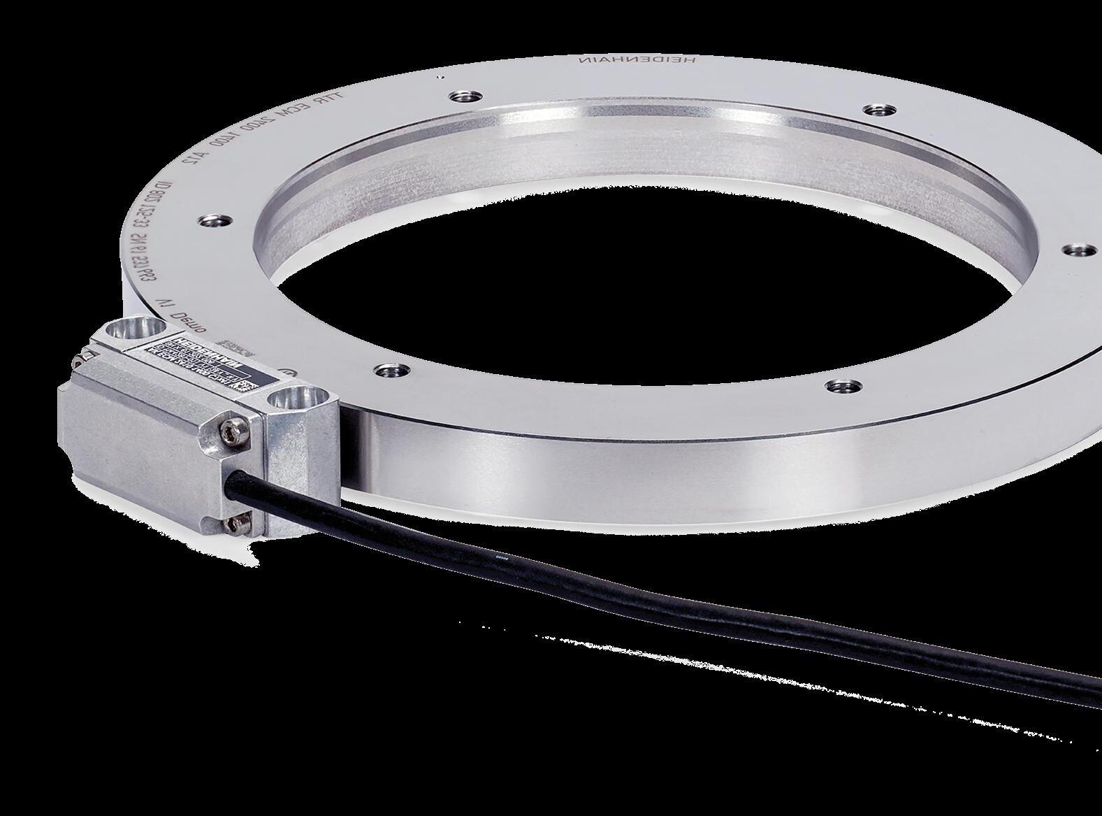
• Integrated Motors
• Linear Guides
• + More
MC² installments include stay
up-to-date

MC² Classroom installments cover topics including essential power-transmission and motion-control technologies for an array of OEM machines, powered end-user products, servo drives, and automated installations.
IN-PERSON EVENTS
Events Manager Jen Osborne jkolasky@wtwhmedia.com @wtwh_Jen
Event Marketing Specialist Olivia Zemanek ozemanek@wtwhmedia.com
VIDEOGRAPHY SERVICES
Videographer Garrett McCafferty gmccafferty@wtwhmedia.com
Videographer Kara Singleton ksingleton@wtwhmedia.com
Front End Developer Melissa Annand mannand@wtwhmedia.com
Software Engineer David Bozentka dbozentka@wtwhmedia.com
Digital Production Manager Reggie Hall rhall@wtwhmedia.com
Digital Production Specialist Elise Ondak eondak@wtwhmedia.com
MARKETING
VP, Digital Marketing Virginia Goulding vgoulding@wtwhmedia.com
Digital Marketing Manager Taylor Meade tmeade@wtwhmedia.com
Digital Design Manager Samantha King sking@wtwhmedia.com
Marketing Graphic Designer Hannah Bragg hbragg@wtwhmedia.com
Marketing Graphic Designer Nicole Johnson njohnson@wtwhmedia.com
Webinar Coordinator Halle Sibly hkirsh@wtwhmedia.com
Webinar Manager Matt Boblett mboblett@wtwhmedia.com.
FINANCE
Controller Brian Korsberg bkorsberg@wtwhmedia.com
Accounts Receivable Specialist Jamila Milton jmilton@wtwhmedia.com
PRODUCTION SERVICES
Customer Service Manager Stephanie Hulett shulett@wtwhmedia.com
Customer Service Representative Tracy Powers tpowers@wtwhmedia.com
Customer Service Representative JoAnn Martin jmartin@wtwhmedia.com
Customer Service Representative Renee Massey-Linston renee@wtwhmedia.com
Customer Service Representative Trinidy Longgood tlonggood@wtwhmedia.com
WTWH Media, LLC 1111 Superior Ave., Suite 2600 Cleveland, OH 44114 Ph: 888.543.2447 FAX: 888.543.2447

DESIGN WORLD does not pass judgment on subjects of controversy nor enter into dispute with or between any individuals or organizations. DESIGN WORLD is also an independent forum for the expression of opinions relevant to industry issues. Letters to the editor and by-lined articles express the views of the author and not necessarily of the publisher or the publication. Every effort is made to provide accurate information; however, publisher assumes no responsibility for accuracy of submitted advertising and editorial information. Non-commissioned articles and news releases cannot be acknowledged. Unsolicited materials cannot be returned nor will this organization assume responsibility for their care.
DESIGN WORLD does not endorse any products, programs or services of advertisers or editorial contributors. Copyright© 2023 by WTWH Media, LLC. No part of this publication may be reproduced in any form or by any means, electronic or mechanical, or by recording, or by any information storage or retrieval system, without written permission from the publisher.
Subscription Rates: Free and controlled circulation to qualified subscribers. Non-qualified persons may subscribe at the following rates: U.S. and possessions: 1 year: $125; 2 years: $200; 3 years: $275; Canadian and foreign, 1 year: $195; only US funds are accepted. Single copies $15 each. Subscriptions are prepaid, and check or money orders only.

Subscriber Services: To order a subscription or change your address, please email: designworld@omeda.com, or visit our web site at www.designworldonline.com
POSTMASTER: Send address changes to: Design World, 1111 Superior Ave., Suite 2600, Cleveland, OH 44114


learn more at: www.designworldonline.com/mc2

2011- 2020 2013 - 2017, 2021 2014- 2016 2014 Winner 6 DESIGN WORLD — MOTION 8 • 2023
Eliminate Maintenance & Optimize Motion
Belt-driven, screw-driven electric linear actuators
• One part number/one supplier

• Quiet and Clean operation
• Self-lubricating
• Corrosion-resistant
• Lightweight

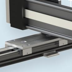
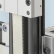
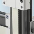
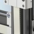
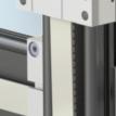
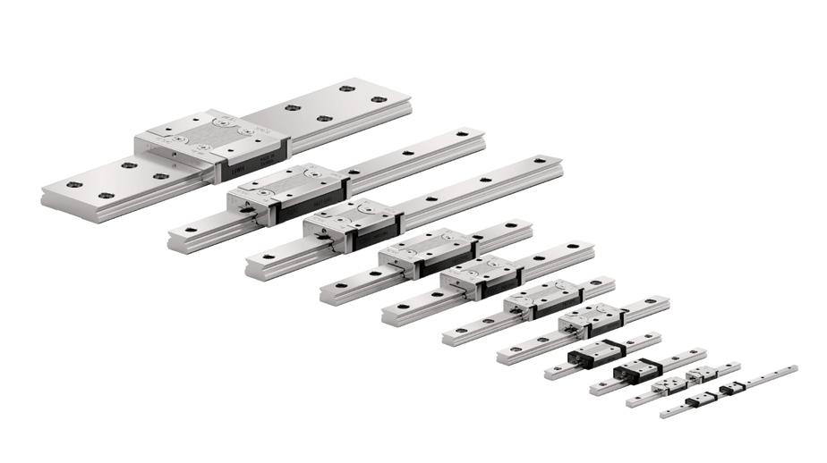
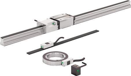
INTEGRATING LINEAR GUIDES, DRIVES, AND ACTUATORS
Linear bearings are included in linear actuators and the axes of other motion systems to guide and support machine assemblies and payloads over the linear stroke. All linear bearings fall into four categories:
8 DESIGN WORLD — MOTION 8 • 2023 motioncontroltips.com | designworldonline.com motion control handbook
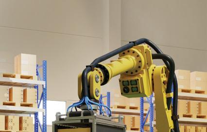
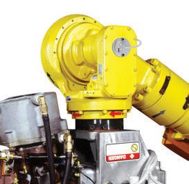
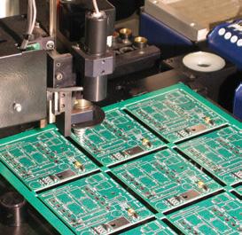
Shown here is a multi-axis linearmotion system to serve as a pickand-place robotic manipulator on an injection-molding machine. Image: Dreamstime • Aleksey Popov
...All In Less Space
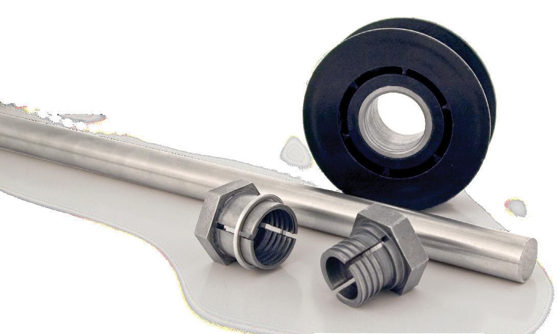
STUDROLLER®
Ultra High Capacity, Zero Slippage, Lower Cost.
For rapid acceleration and deceleration:
• 30~600mm rail lengths
• 2~12 mm rollers
• 150 million cycle endurance

Now Available in All Stainless Steel.
Load capacity is increased up to 250% over competition’s by greater roller-to-rail contact
Number of rollers is 20% to 55% greater than competitions.
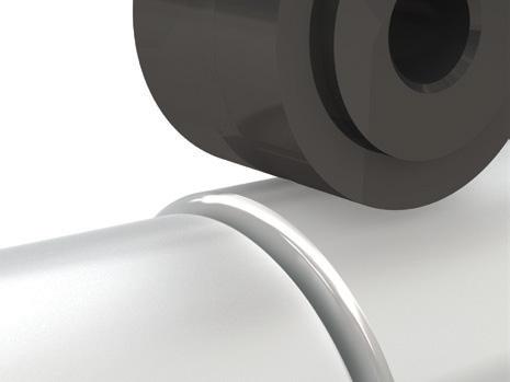
Raceway’s depressions track STUDROLLER’s nodules preventing slippage - in any position. (Patent Pending)
 Stainless Steel retainer
The interrelated functions of these linearmotion components to both support (bear) loads and guide loads is the core reason why they’re called both linear bearings and linear guides — depending on which function is being emphasized by the source. Both terms are so generic that they can refer to any products from the four categories listed above — including such disparate designs as plain linear bearings, ball bushings, and recirculatingroller linear bearings. Confusing matters is the fact that industry makes inconsistent use of even more specific linear-motion terms. For example, the term slide is often used to refer to the carriages of linear bearings based on rolling (not sliding) bearing elements. The term
rolling-contact guide is often used to refer to profiled-rail linear bearings even though trackroller linear guides also include rolling contact (at their track wheels).
That said, linear guide often indicates a standalone guide rod, ball slide, or mechanism solely for guiding loads. The term profiled rail nearly always indicates some linear bearing with roller or ball elements. Many manufacturers use the terms linear slide (whether based on rolling or sliding action) and linear rail (whether plain, track-roller, or profile) to indicate a linear-motion guide element that’s incorporated into a build complete with some mechanical drive. Though the terminology surrounding plain linear bearings is probably the most consistent, various manufacturers use plane bearing (as in one dimension in 3D space) instead plain bearing. While the two terms are often used interchangeably, the American Bearing Manufacturers Association encourages use of the term plain bearing.
The term linear stage generally implies a design has guided elements as well as some mode of mechanical linear actuation and reinforced body — often sans inclusion of the motor.
So-called motorized rails (more commonly
called linear actuators) abound — though the distinction here is that there are countless linear actuators sold without any linear-guide element. That’s useful for OEMs aiming to employ some specialized linear guide or omit guides altogether.
Profiled-rail options in context
Profiled-rail linear bearings introduce very little friction into linear systems ... usually significantly less than that introduced by linear bearings based on sliding friction. Frictionforce variations due to speed are minimal, so these components can position loads with small and precise steps. Their low friction also allows high speeds without generating too much heat ... which in turn minimizes wear to help machinery maintain long-life accuracy.
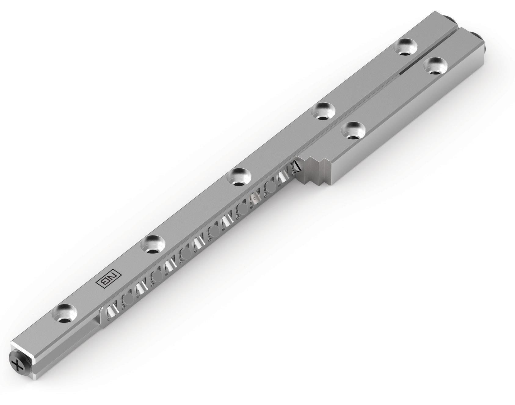
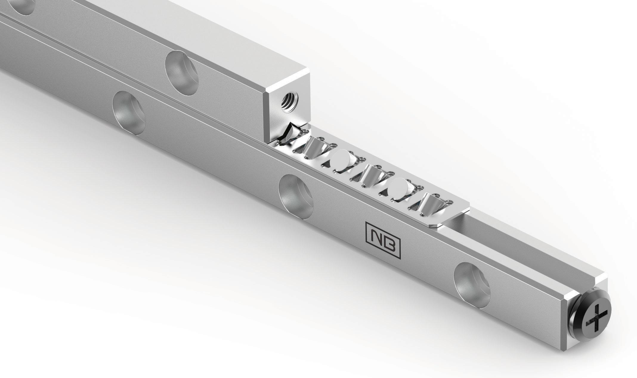
Rolling elements are either cylindrical rollers or balls. Carriage assemblies that recirculate the rolling elements have stroke lengths only limited by the linear rail upon which they ride. In contrast, carriage assemblies that hold the rolling elements in a non-recirculating arrangement limit stroke length. Flat guideways are dominant here; many of these sport a grooved race compatible with what’s known as the crossed-roller arrangement.
10 DESIGN WORLD — MOTION 8 • 2023 motioncontroltips.com | designworldonline.com motion control handbook
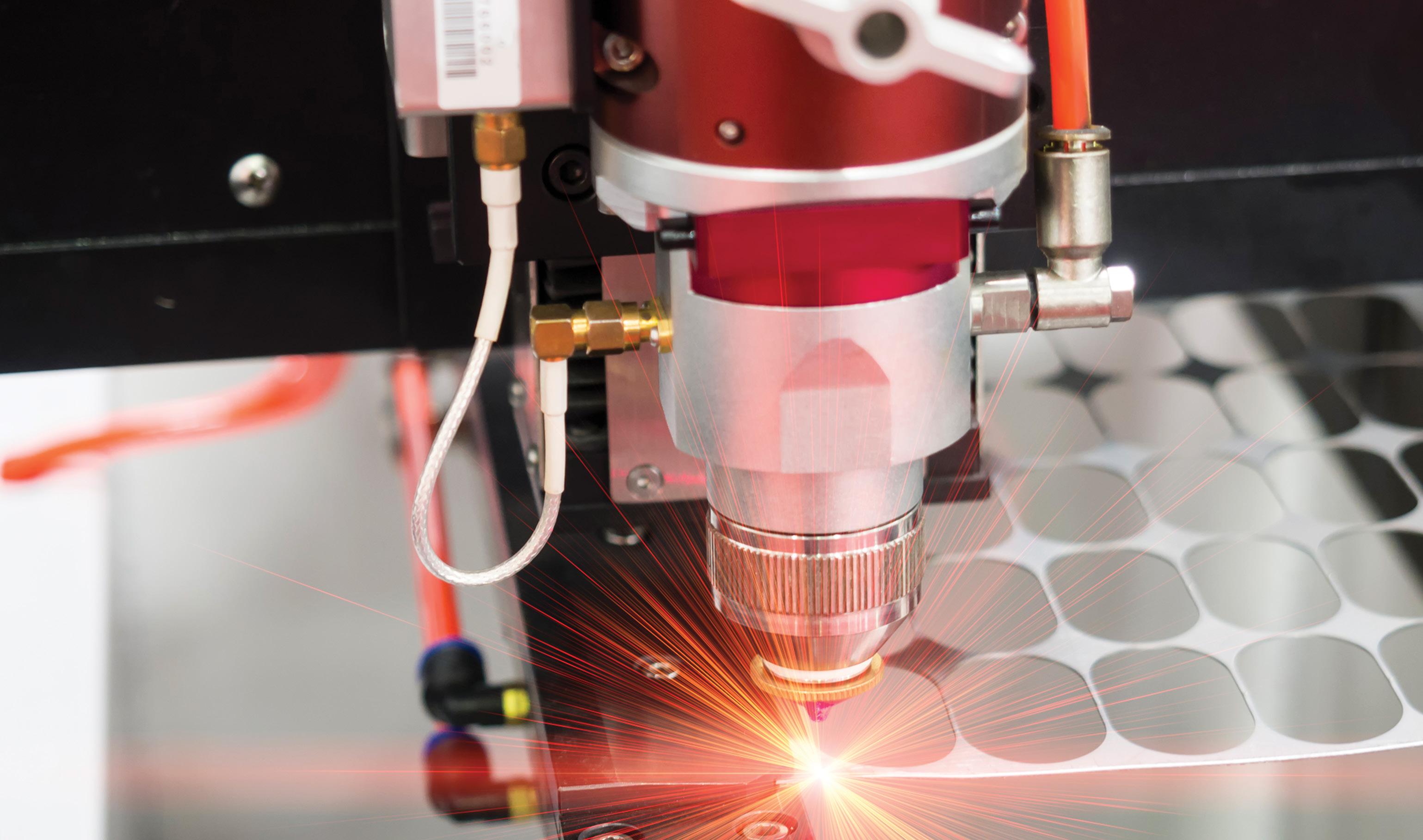
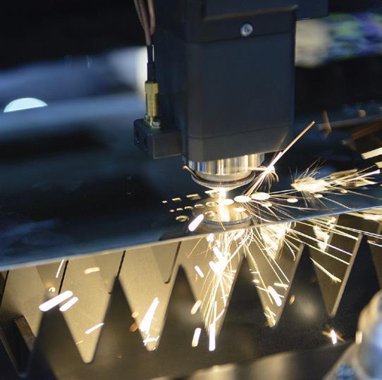
Here a CNC laser-cutting machine uses round rail linear guides.
Image: Dreamstime • Sorapol Ujjin
1. A carriage or comparable table rides on a linear rail or track via plain (sliding) elements
2. A carriage rides on linear rail via wheeltype track rollers
3. A carriage rides on a profiled linear rail via carriage-contained arrays of ball bearings or cylindrical rollers
4. A bushing studded on its inner diameter with rolling elements rides on a round shaft.
Profiled-rail linear bearings employing balls are also subdivided into recirculating and non-recirculating types. Flat guideways here typically accommodate double-row recirculating ball arrays. The load capacity of profiledrail linear bearings employing balls depends on how many rows of balls the carriage carries … and more rail rows mean more load capacity and rigidity. That said, more rows also make these profiledrail linear bearings more complex and costlier.
While the organization of balls in rolling-ball-element linear bearings isn’t an officially defined specification standard, it’s typically detailed in manufacturer catalogs. That’s because ball positioning — called the raceway arrangement — has a huge impact on performance. This defines both where and how the load-bearing balls sit on the profiled linear rail.
The face-to-face raceway arrangement
is often called the X arrangement because the contact lines between the balls and the raceways point inward ... making an X inside the profiled rail. This arrangement gives the assembly equal load capacity in all directions but reduces its ability to handle moment loads. The back-to-back raceway arrangement is also called the O arrangement because the contact lines point outward — making an O around the rail. This design gives a longer moment arm and allows the bearing to withstand high moment loads.
Profiled-rail linear-bearing suppliers generally sell linear bearings of a given raceway arrangement in a few geometries to satisfy various design requirements for friction minimization and load capacity. Circular-arc geometry produces twopoint contact between the ball and the raceway. This gives the assembly a lower friction coefficient and smoother running characteristics. Gothic arch
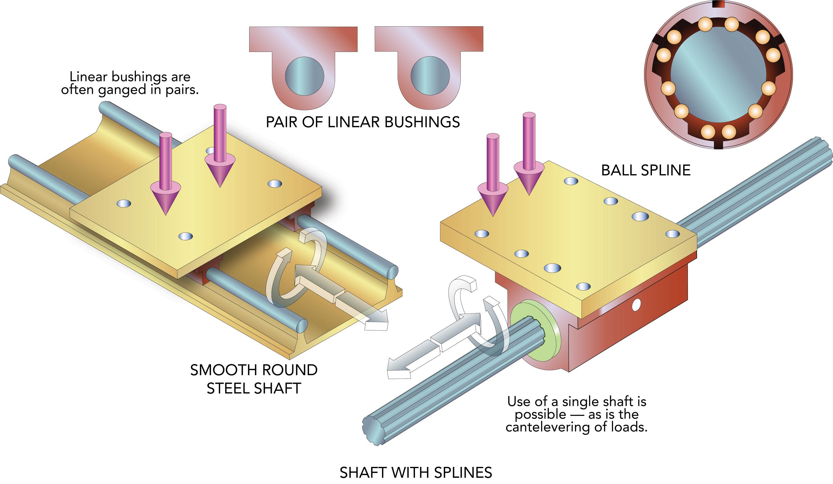
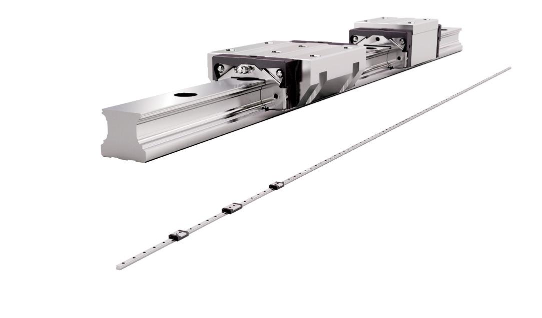
Unlike linear systems based on ball splines, other linearbearing types often necessitate twin rails or mechanisms.
linear motion 11 DESIGN WORLD — MOTION 8 • 2023 motioncontroltips.com | designworldonline.com
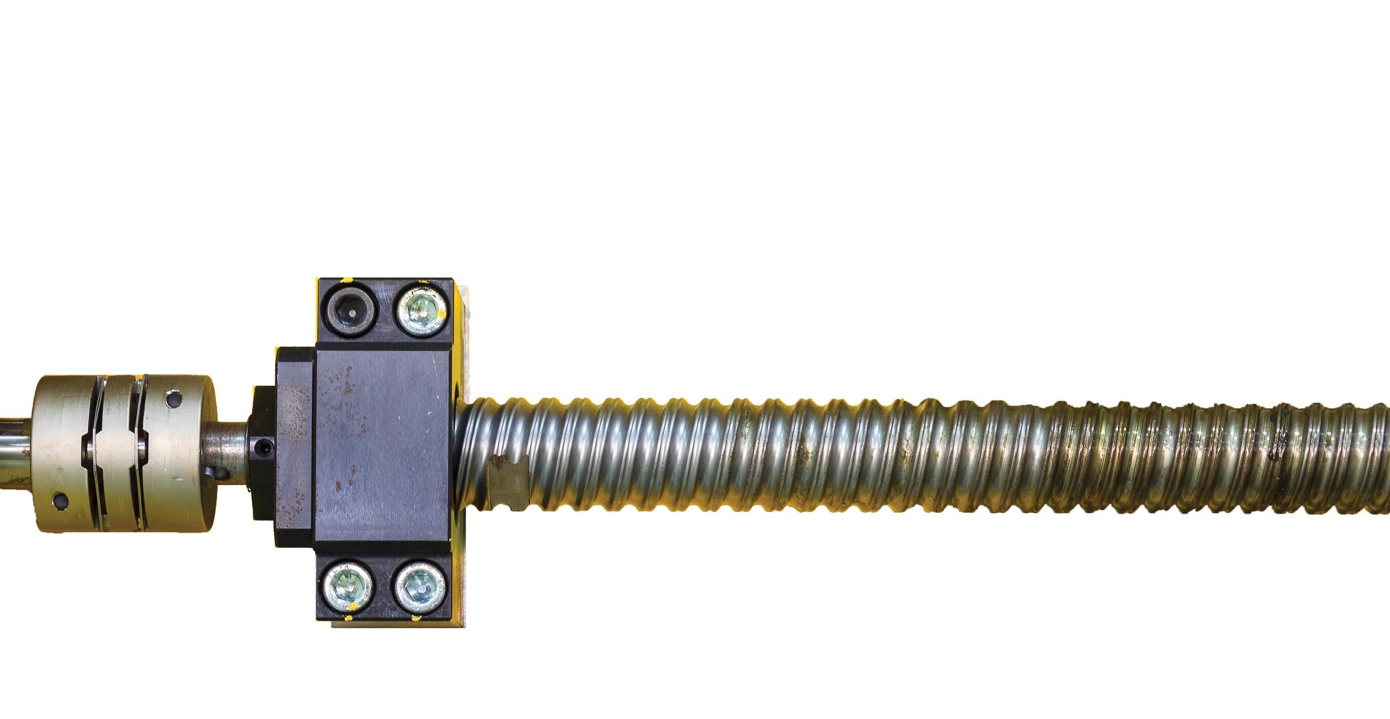
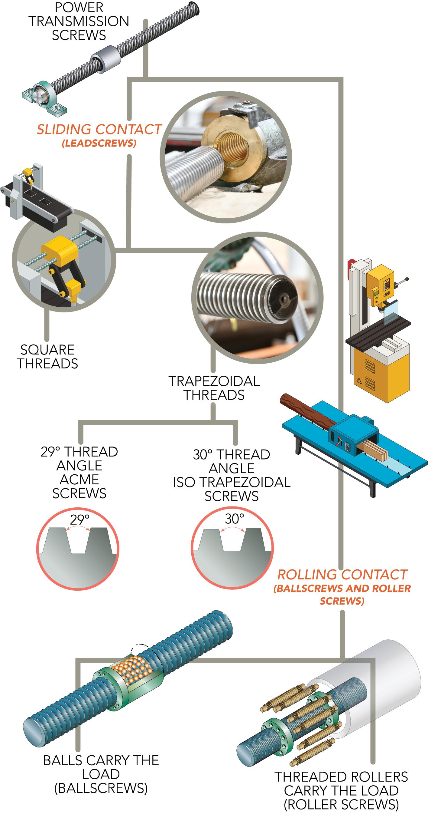
Rotary-to-linear screws abound to convert rotary electric-motor output to linear strokes. Shown here are just a few ways in which these screws are classified.
geometry provides four-point contact between the ball and raceways, resulting in higher moment load capacities … but also higher friction. More specifically, the Gothic arch design provides two contact points on the ball and two contact points on the raceway.
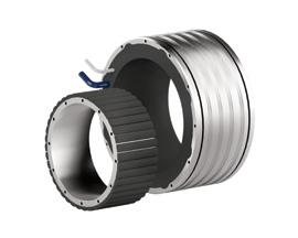
More on round-shaft options
Linear bushings (sometimes called ball bushings) are a type of linear bearing that includes two basic components: A hardened shaft having a round or modified circular cross section as well as a sleeve-shaped cylindrical nut (usually called a bushing) having captive circuits of recirculating balls. The bushing (via its ball-bearing elements) rides along this hardened shaft (usually made of specially engineered steel) to provide low-friction linear guidance.
Linear bushings were first patented in 1940s and became commercially available in the 1950s. Until the profiled-rail linear guides came onto the motioncontrol scene in the 1970s, these linear bushings were the primary form of linear-motion bearing support for applications not requiring the high load capacities and accuracies delivered by machined linear ways. But make no mistake: As linear-bushing designs evolved over the decades, their increased load capacities and new selfaligning capabilities have meant they’ve endured as a top choice for linear guidance in motion applications.
Today linear-bushing shaft sizes range from the miniature (to just a couple millimeters in diameter) to 100 or more millimeters — allowing application in packaging, paper processing, assembly, and general-automation applications.
One caveat: Linear bushings provide widely applicable load-carrying capacities with very low friction but (despite their simple design and easy installation) do require precision sizing during specification. Myriad factors affect linear bushing life and failing to account for these parameters during sizing could make for a machine design that’s undersized for the application or one that fails to deliver the expected travel life.
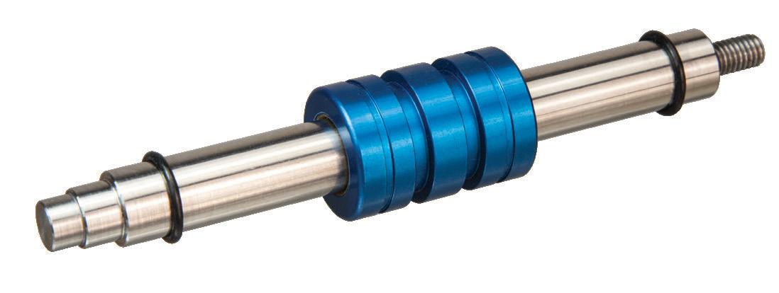
Now consider ball splines. Ball splines are often lumped together with linear bushings — with some manufacturers even calling them torque-resistant ball bushings. But ball splines offer functionalities beyond those of traditional linear bushings. That’s because ball splines integrate:
• An essentially round shaft having precisionmachined lobes or grooves down its axial length
• A sleeve-shaped cylindrical nut having captive circuits of recirculating balls in protruding arrays that are compatible with the mating shaft’s particular geometry.
12 DESIGN WORLD — MOTION 8 • 2023 motioncontroltips.com | designworldonline.com
motion control handbook


Precision Linear Motion when you need it NOW! Order Today! 800.245.5013 • deltron.com ISO 9001:2015/AS9100D CERTIFIED MADE IN USA Linear Motion Specialists deltron.com 800-245-5013 Solid Models Available for all Del-Tron Model Numbers Standard And Custom Engineered Linear Motion Components Designed to Serve A Wide Variety of Markets
motion control handbook
Here, the nut is much like that of a ballscrew assembly, but (at least in most cases) with a screw having a 0° lead angle. The exception to this is rotary ball splines, which feature spiraling grooves down their shafts.
In fact, ball-spline shafts can have two or more grooves running down their length — with the exact groove count depending on linear-bearing load capacity and shaft diameter.
Just as their linear-bushing cousins, ball splines are also available in a wide array of diameters — to serve in machine-tool punching or riveting machines (often on their Z or Zϴ axes) as well as grinding equipment, transfer machines, wire winders, indexing stations, and various machines’ spindles.
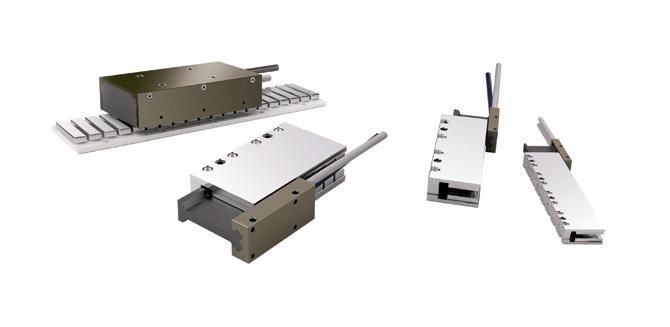
Drives in the context of linear actuation
Many of the core linear power-transmission technologies used in today’s modern
industrial-automation applications have been in use for 50 or more years. However, their design and manufacture (as well as their modes of integration) have continually advanced to allow increasingly sophisticated actuation capabilities and applications. Complementing these modern iterations of mechanical components are motion controls and feedback devices (both electronics hardware and software) with unprecedented functions and flexibility.
Except for pneumatic, solenoid, piezo, electrohydraulic, and linear-motor designs, the core of all linear-motion systems is a rotary electric motor paired with some mechanical rotary-to-linear device.
The latter converts the high-rpm rotary motion motor output into a linear stroke.
More common options include:
• Ballscrews
• Roller screws (planetary and differential types)
• Leadscrews and (especially for vertical applications) jack screws
• Belt drives, chain drives, and pack-andpinion sets
More exotic power-transmission components for linear motion include:
• Rigid-chain assemblies that lock in one direction to push loads
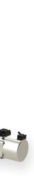
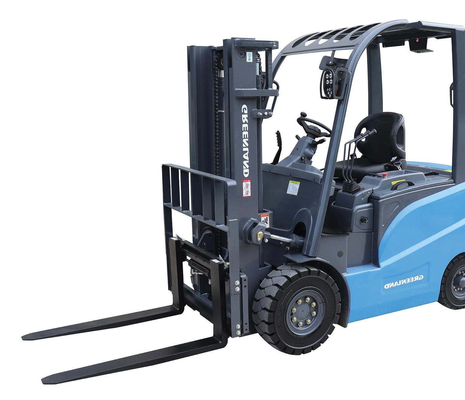
Electric thrust actuators incorporating both ballscrews and roller screws have come to rival hydraulic cylinders for some applications — capable of delivering hundreds of kN. Shown here is an all-electric GEF-2500 forklift from Greenland Machinery employing such actuation.
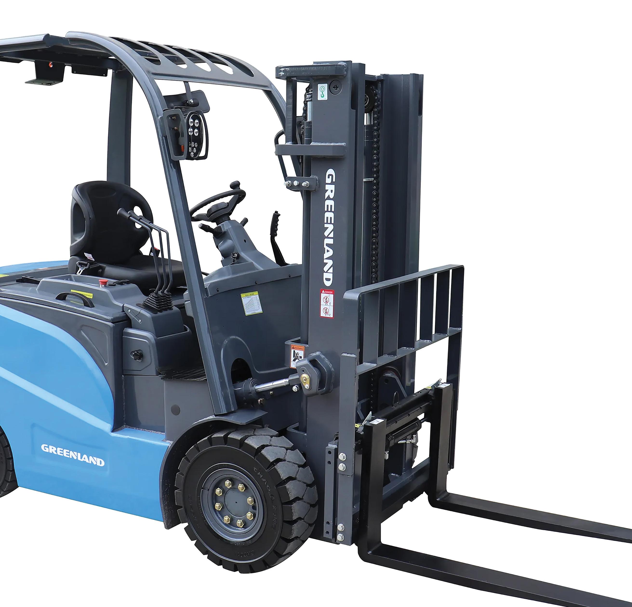
14 DESIGN WORLD — MOTION 8 • 2023 motioncontroltips.com | designworldonline.com
• Slider crank, disc-cam, and walkingbeam drives
• Cylindrical-cam and set axis mechanisms
• Traction drives and skewed-roller rods
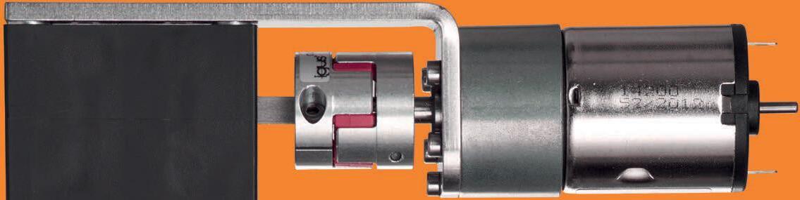
Confusing matters is that sometimes these rotary-to-linear mechanical devices are themselves called drives or (worse yet) actuators. We reserve the term actuator to mean those fully integrated “muscles” that include a motor with or without gearing, coupling if applicable, rotary-to-linear component, and (in most cases) some frame and linear component to bear or support and guide the translated load.
Ballscrews are occasionally called ball shafts — especially by global suppliers. A rudimentary form of the component was first proposed in the 1800s with spherical rollers between a leadscrew-type screw and nut pairing. However, not until the

1940s were manufacturing capabilities precise enough to allow the production of ballscrews as they’re known today.

These early ballscrew progenitors were widely applied in the U.S. and German automotive industries — as recirculating-ball steering assemblies having nuts threaded on their exterior to make with a worm gear in turn linked to the steering wheel. Further improvements were made to early ballscrew designs by Japanese manufacturers — first for the automotive industry and then for the machine-tool industry. More specifically, computer numerical control (CNC) tools made copious use of ballscrews to replace leadscrews on all three of the machining axes … and ballscrews still find unrivaled use in such machines today.
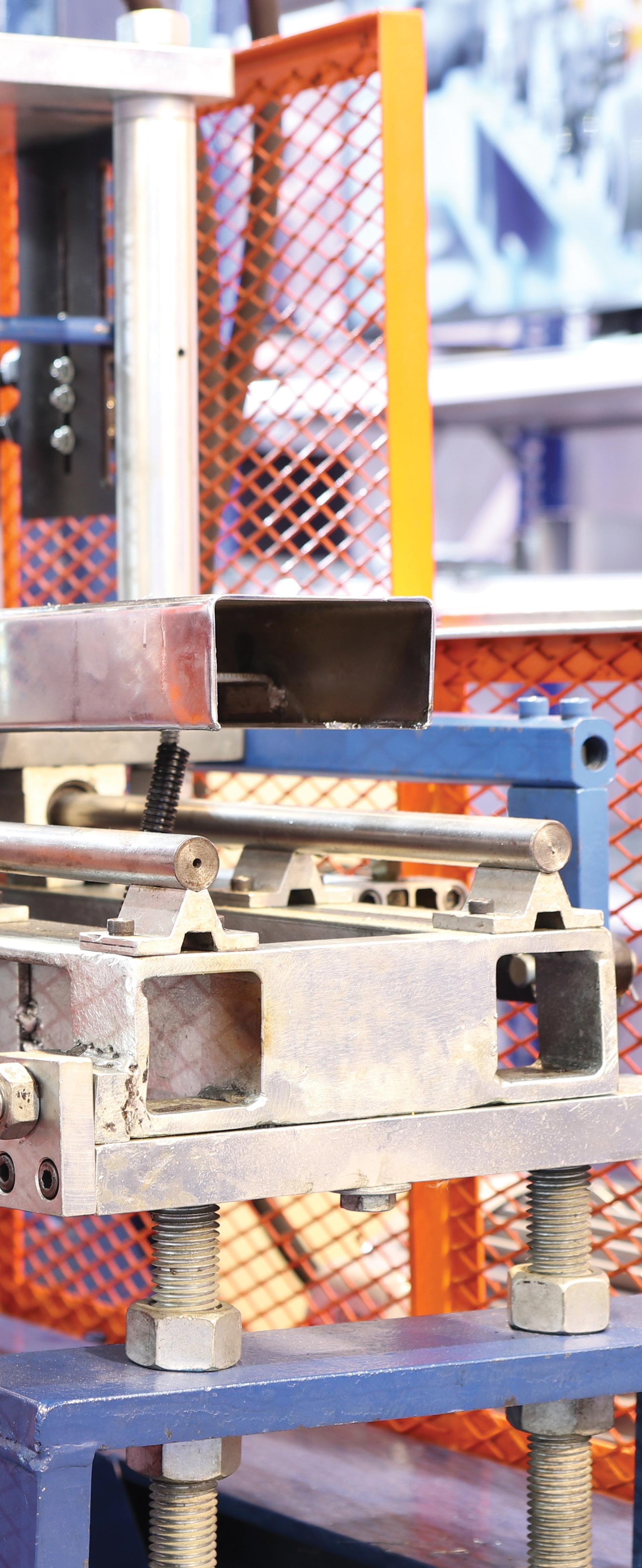
The load-bearing linear guides most paired with ballscrews and roller screws are track roller linear guides (especially on

high-speed axes and those to deliver high thrust force) and profiled rail linear guides. Because screw-driven actuators require end bearings that must be rigidly mounted, they are often enclosed in an aluminum extrusion.


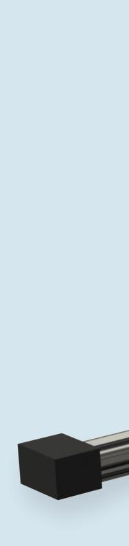
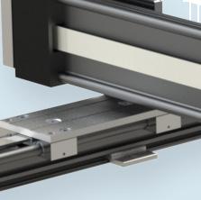
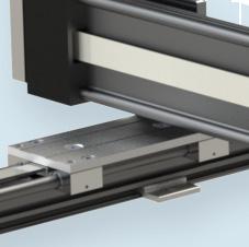
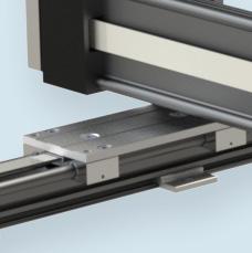
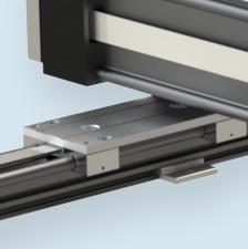
However, when high travel accuracy is required, ballscrew types are commonly offered with a machined steel housing. In fact, ballscrew-driven actuators come in both slider and rod types. Slidertype actuators are what most engineers picture when conjuring a linear actuator in their mind’s eye. The motion is contained within the limits of a housing and the load is mounted to a slider — also called a carriage, saddle, or table. In rod-type actuators, the motion is produced by a rod that extends and retracts from a housing. The load may be mounted to the end of the rod … or the rod can be used to push the load. One common application is the
15 DESIGN WORLD — MOTION 8 • 2023 motioncontroltips.com | designworldonline.com linear motion
pressing or stamping of labels onto cartons … or pushing defective products to a diverter lane along a conveyor.
Slider-type actuators can be guided by recirculating or plain bearings, depending on the load for which they’re designed. In contrast, rod-style versions are not typically designed for radial loads from downward or sideways force vectors. Instead, they usually include use simple plain bearings to provide guidance to the rod without significantly contributing to load-carrying capacity.
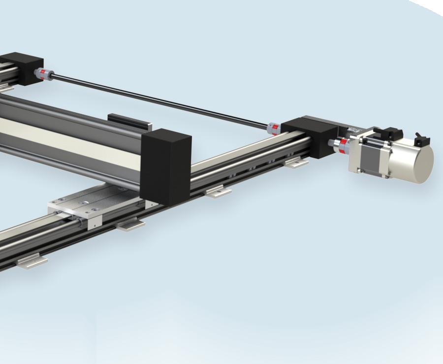
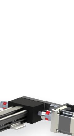
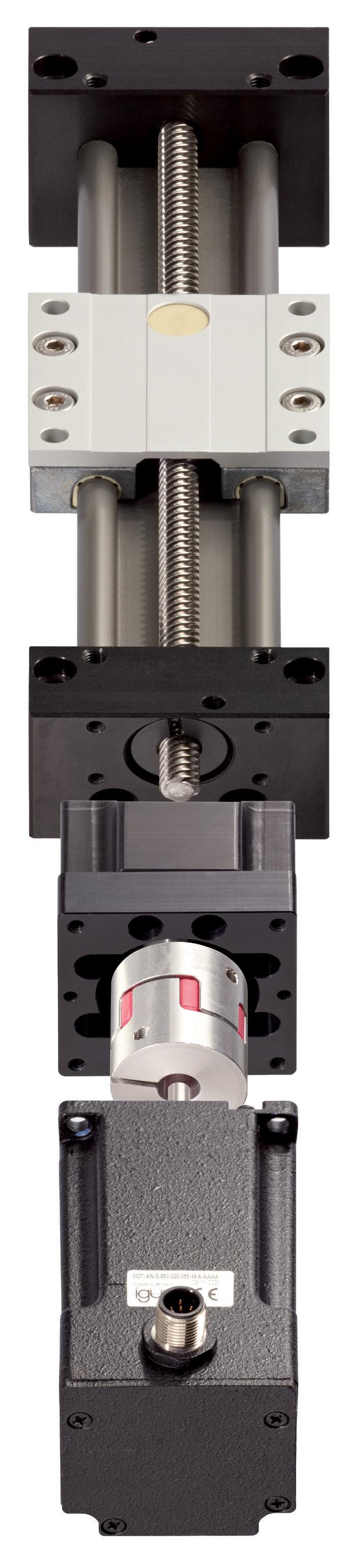
Deeper dive on NEMA stepper actuators
NEMA 17 and NEMA 23 actuators install on machine axes that necessitate the conversion of the motor’s rotary output to linear motion. In the past, OEMs and end users assumed all integration of such actuation — including the procurement of motor, coupling, and screw — and all their assembly. Today, it’s more common for machine builders (whether designing for a few dozen axes or thousands of axes) to specify turnkey linear subsystems to free design time and focus on core engineering competencies.
Of course, NEMA stepper linear actuators aren’t the only screw-based linear-actuator type around. With integrated motor and screw assemblies, the motor can be either a servo or a stepper type, and the screw can be a ballscrew or a leadscrew … although the most common configurations pair a leadscrew with a stepper motor or a ballscrew with a servomotor.
Stepper motors for linear actuation include single and doublestack variations that run open or closed loop … with some actuators even incorporating programmable electronics if required.
These linear actuators are named for the standard size-related designations of their motors … with (as mentioned) NEMA-17 and NEMA-23 linear actuators the two most common sizes. (Recent years have brought increased use of NEMA 34 stepper linear actuators as well.) In these actuators, NEMA 11, 17, and 23 motors pair with leadscrews in imperial or metric variations to yield linear resolutions to 0.10 mm or better — even to 0.4 mm while delivering forces to 1,000 N in some cases.
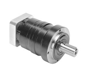
NEMA stepper motors in linear-actuation applications produce maximum torque when the motor is at standstill … and continue to provide very high torque at speeds to 1,000 or 1,200 rpm. In contrast, servomotors often require a gearbox to multiply the torque and reduce the speed from the motor. But the addition of a gearbox reduces system stiffness by introducing backlash and compliance.
Because stepper motors don’t necessarily require mechanical gearing to produce high torque at low speeds, they also have an advantage in overall system stiffness for these applications.
Because they produce full torque at standstill, stepper motors can hold a load in place even against external forces — and run open loop. This is especially useful in:
• Processing applications
• Where loads are held stationary while some machining or assembly task is performed
• While waiting for the next movement.
16 DESIGN WORLD — MOTION 8 • 2023 motioncontroltips.com | designworldonline.com motion control handbook
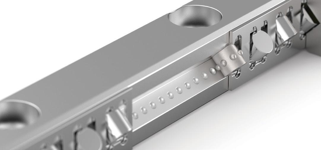
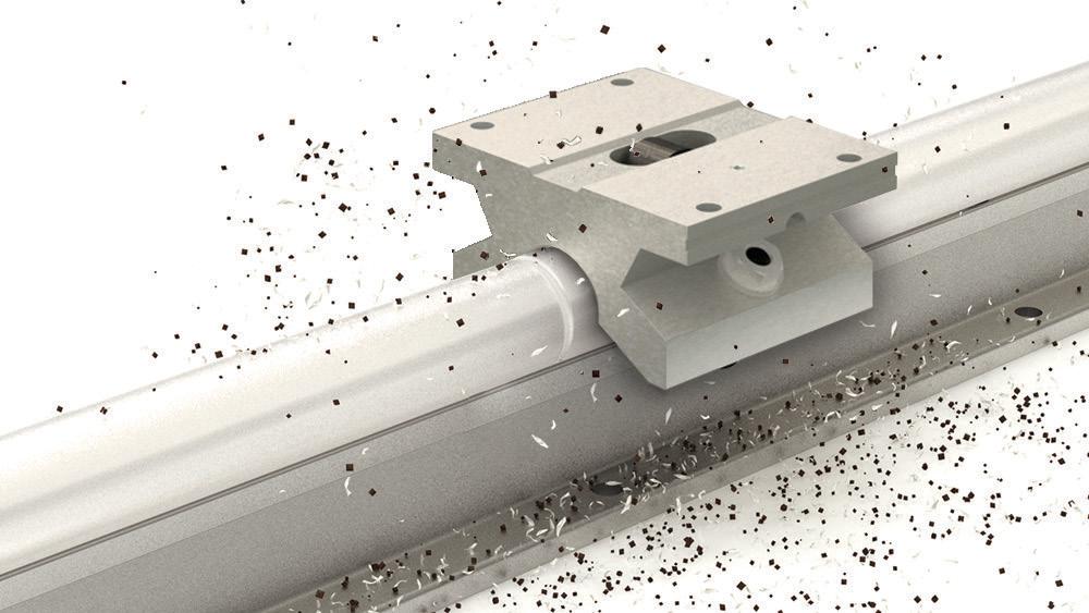
Shown here are round-rail linear bearings in a coldrolling machine-tool application. Image: Dreamstime
Steel, Stainless Steel, and Aluminum Shafting cut to length and optimized for use with LEE Linear bearings.
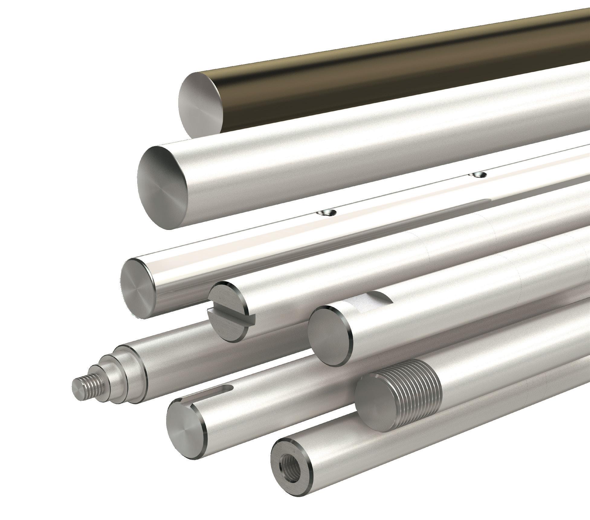
LEE Linear has the ability to manufacture custom shafting to required standards in a short amount of time, eliminating downtime and increasing profits for our customers.

Special machining capabilities include threading, diameter reduction, flats, keyways, plating, and more.

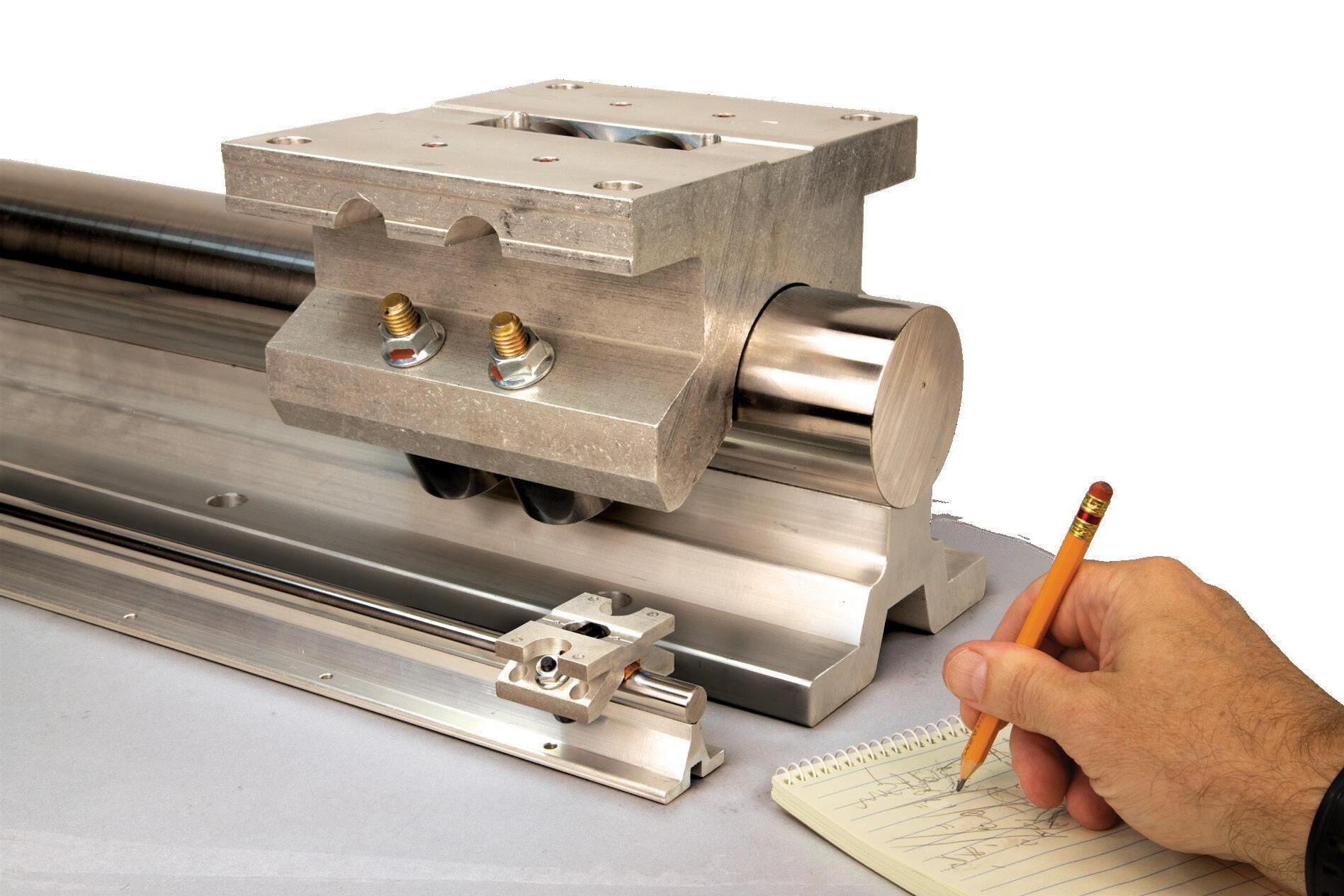
Roller Pillow Blocks are well suited for heavy loads and long travels.

Large cam follower design delivers superior contamination resistance and excels in applications requiring joined shafts or rail assemblies.
Simplified installation and alignment makes for lower system costs.
Request a FREE Sample at 6402 E. Rockton Rd. Roscoe, Illinois USA +1.800.221.0811 sales@leelinear.com leelinear.com Flexibility to
Meet Your Needs
bit.ly/DW-LEE2023
CONVERGING TRACKS IN MOTION-CONTROL HISTORY
Except perhaps for the well-defined standards of the National Electrical Manufacturers Association (NEMA) for step motors, there are few consistent naming conventions for product types in motion-control and discrete-automation industries. So instead of a standard, engineers will often refer to the maker of a given component to describe an arrangement — as in a Kollmorgen servomotor or Parker servomotor or a Siemens servomotor, for example — though it’s rare that they’re exactly equivalent products. European suppliers do follow IEC guidelines but not strictly so, as a servomotor (to continue with that example) might have IECstandard mounting but shaft with supplier-specific dimensions.
Such terminology inconsistency applies to motion controllers as well. Here it’s helpful to remember that decades ago, motion design involved two separate (but slowly converging) disciplines — one discipline called motor control and another discipline called motion control.
18 DESIGN WORLD — MOTION 8• 2023 motioncontroltips.com | designworldonline.com montion control handbook
Motor control informs motion control
Historically (and to this day) companies first focused on motor control primarily concentrated their engineering on hardware and techniques to convert 110, 230, or 24-V input into formats for smoothly, accurately, and efficiently powering (driving) electric motors. Their main concern was the shaping of current and voltage into motors as with pulse-width modulation (PWM) or field-oriented control (FOC) to spur a specific kind of mechanical output. This involves the design of drive bipolar transistors, MOSFETs, or (leading today) IGBTs along with other switching amplifier circuits, pre-drivers, current sensing, and overcurrent and short-circuit protection to make that mechanical motor output happen.
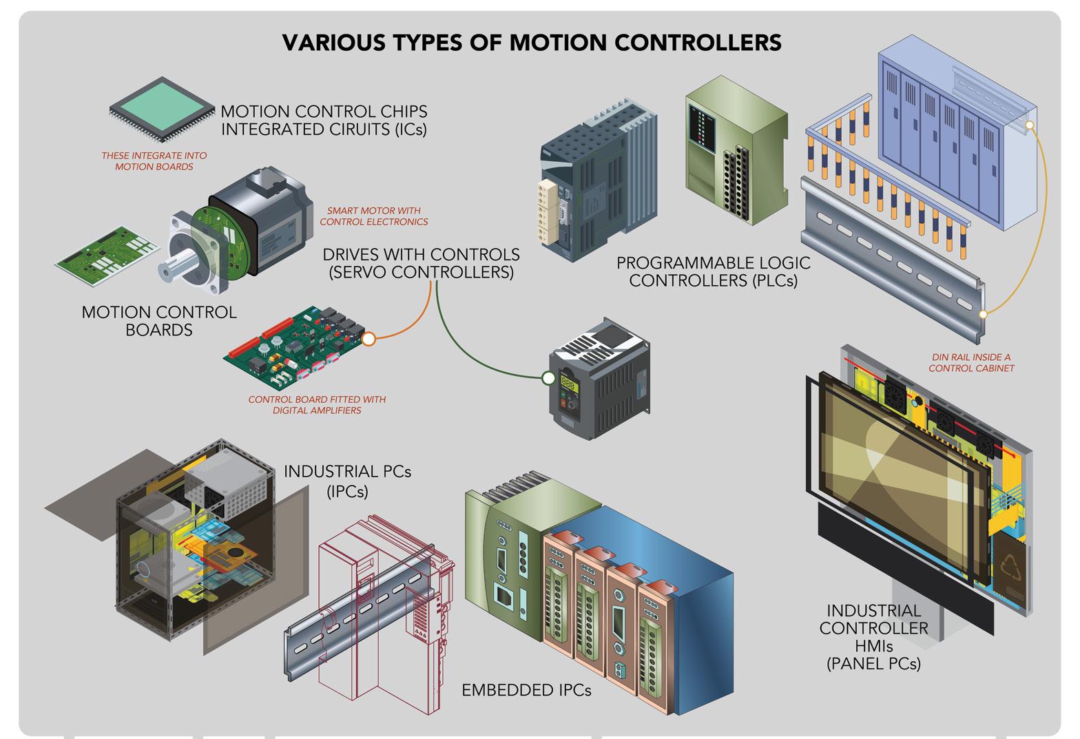
To this day, these motor controllers (also called amplifiers, drivers, and drives) are sold as integrated “box” (housed and connectorized) packages that mount into control panels ... or card and board (chip-level and module-level) products that OEMs must integrate into their own machine or designed circuit board.
As digital signal processors (DSPs) and microcontrollers became more powerful, motor-control companies began upgrading their offered products and making them more sophisticated. Motor controllers (drives) became digital and even began assuming motion-control tasks associated with computations related to achieving set accelerations, velocities, and positions — essentially servo functions. These evolved into offerings that accept various voltage inputs and accommodate various motors at their outputs.
Motion control takes on motor control
Companies tracing their origins to motion control (just as those with origins in motor control) have also leveraged ever-more capable electronics on the market. These suppliers (such as Galil, G&L, Kollmorgen, and Siemens) historically focused their engineering on improving electronics and software for motion control — such as coordinating (through motor drives) multiple motor-driven axes and steering them through 3D position trajectories in space. These suppliers too ultimately came to eliminate problems OEMs and other customers had with making drives and controls work together — by offering fully compatible components or pre-integrating drives right into their controls.
Today, integrated drive-controller options abound … as do the interfaces to support various architectures; the offerings of motion-control companies have also converged with those from motor-control companies as well as motionsupplier newcomers underscoring holistic “motor+motion” design approaches. Today design engineers can find “drive+controller” products sold as standalone motion controllers (capable of accepting and storing motion programming) for simple applications — or as hardware options to support what’s called distributed motion control — covered in more detail at motioncontroltips.com/faq-what-isdistributed-architecture-for-servo-drives.
When used for the latter (as distributed drives) these connect into networks to support synchronization. Such drives accept more basic position and move commands on the network from a primary host motion controller (whether PC or motion controller board) but execute some to most all other amplifier and motionprofile-generating tasks.
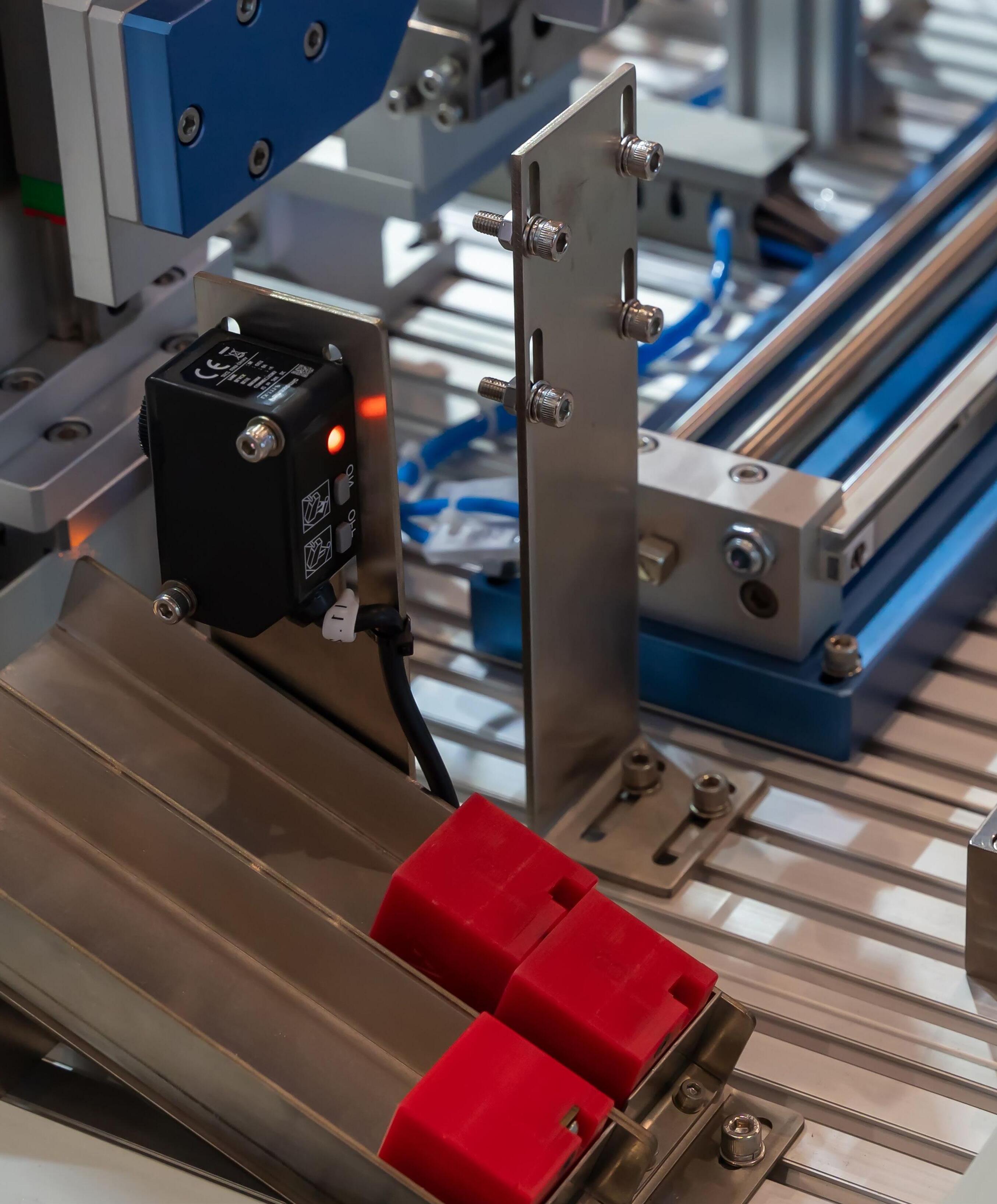
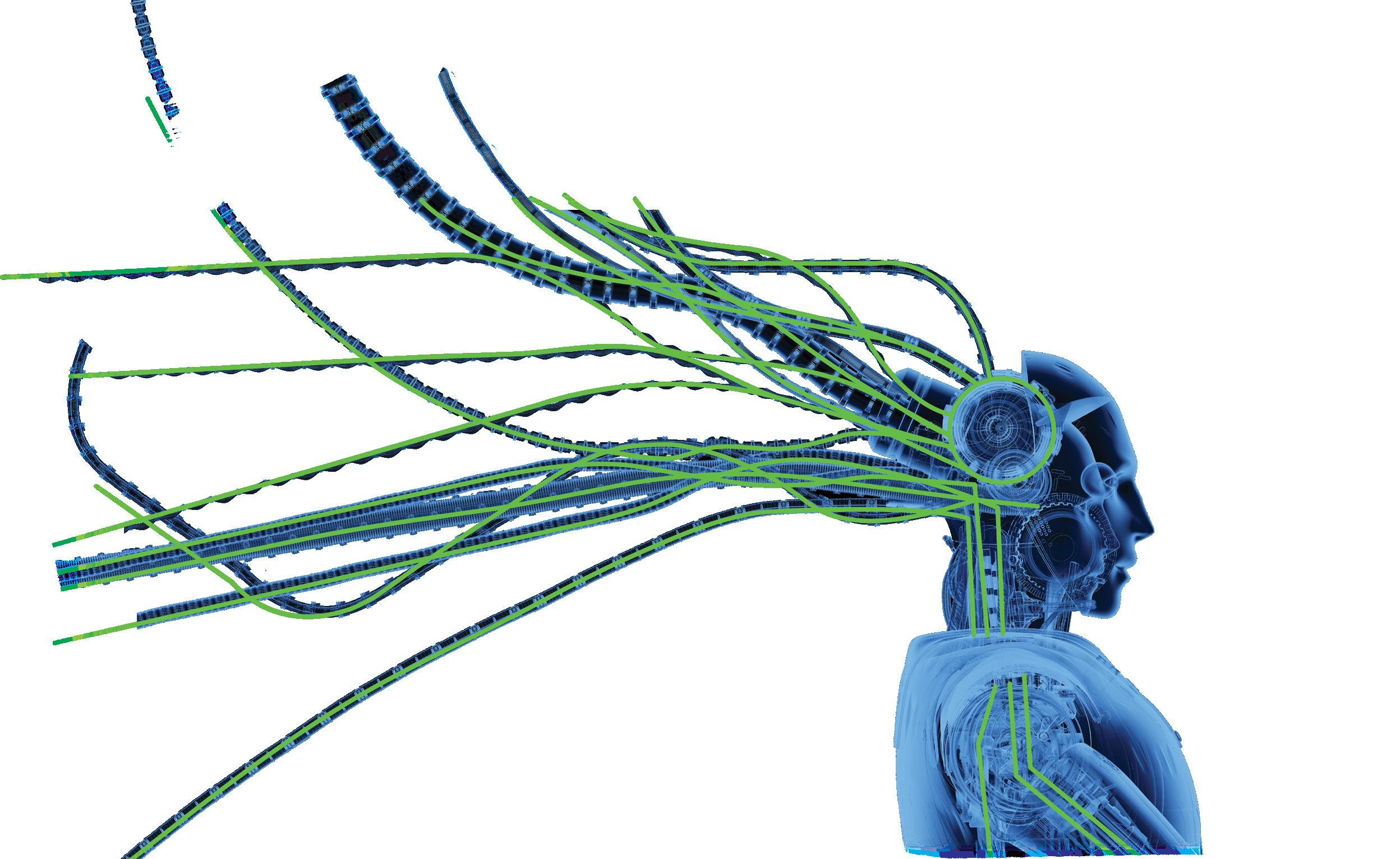
If we use a zoological analogy to describe automated motion systems, motion controllers serve as the system’s brains to monitor, command, and integrate:
• Appendages and axis muscles — moved by electric motors and drives, actuators, and attached mechanical components
• Senses — in the form of industrial sensors and other encoder and even machine-vision feedback
• Informational input from the external environment to inform adjustments — from machine operators as well as IIoT networks communicating enterpriselevel order and throughput requirements.
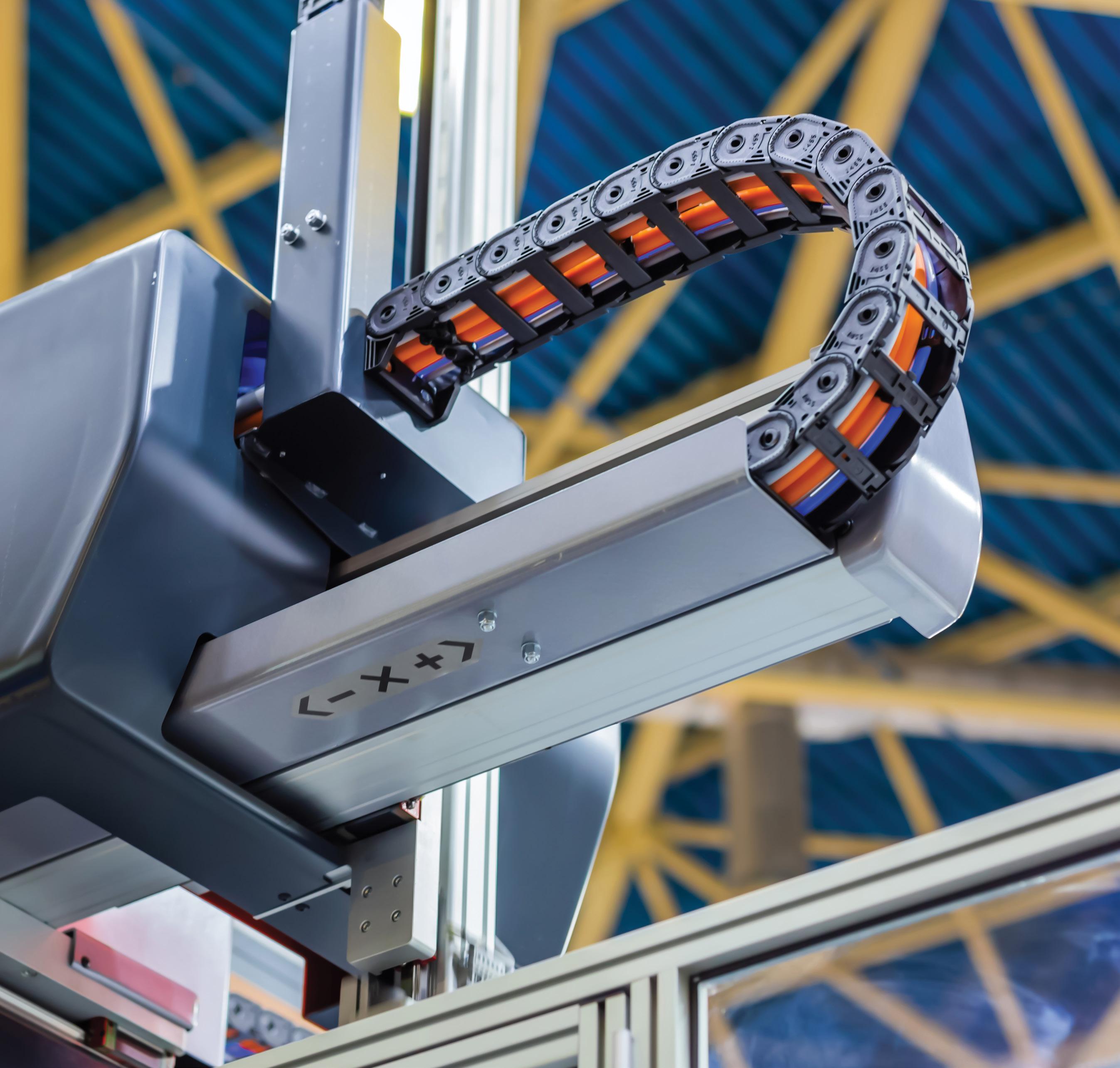
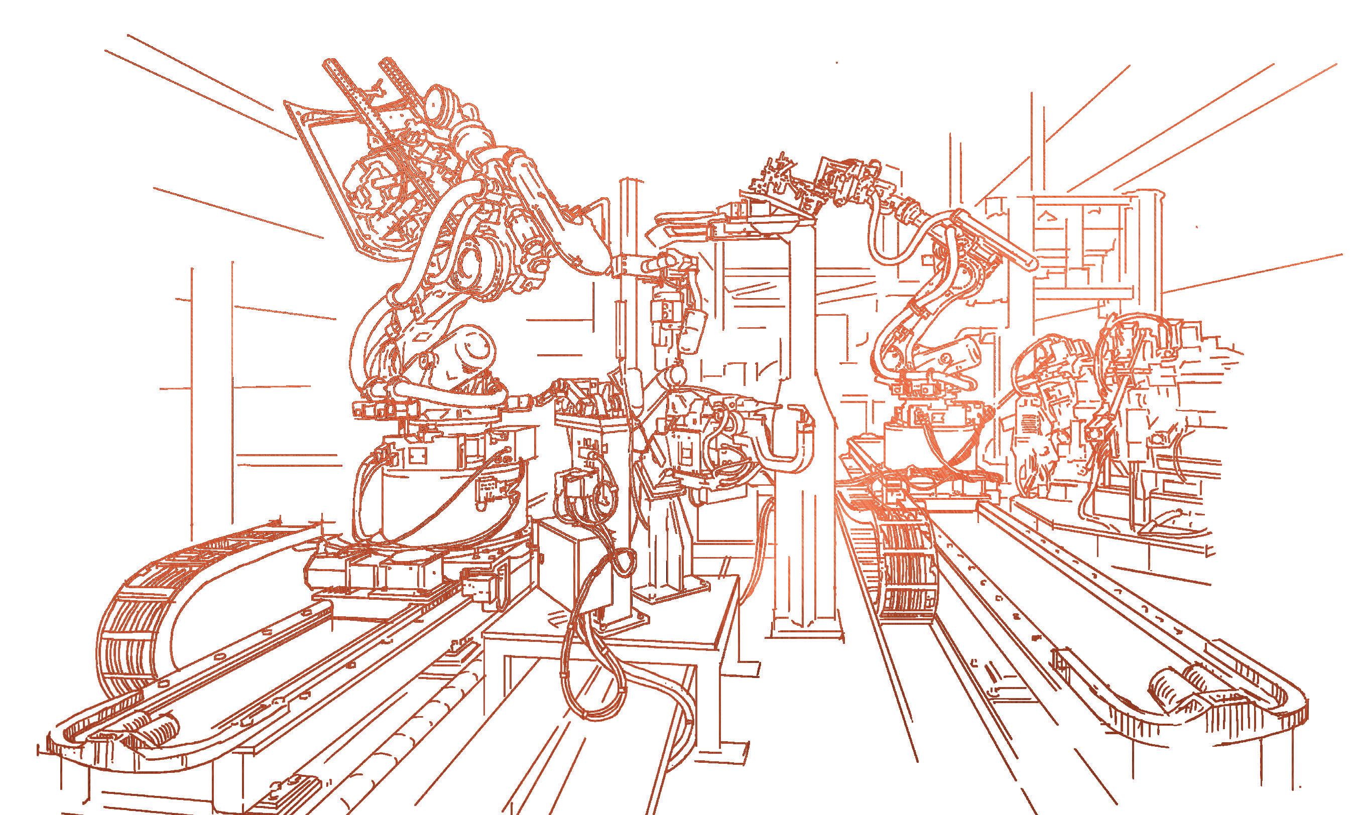
 Distributed motion controls complement automated assembly machine designs.
Image: Wirestock
controllers
Distributed motion controls complement automated assembly machine designs.
Image: Wirestock
controllers
19 DESIGN WORLD — MOTION 8 • 2023
Stainless Steel Gearmotors.

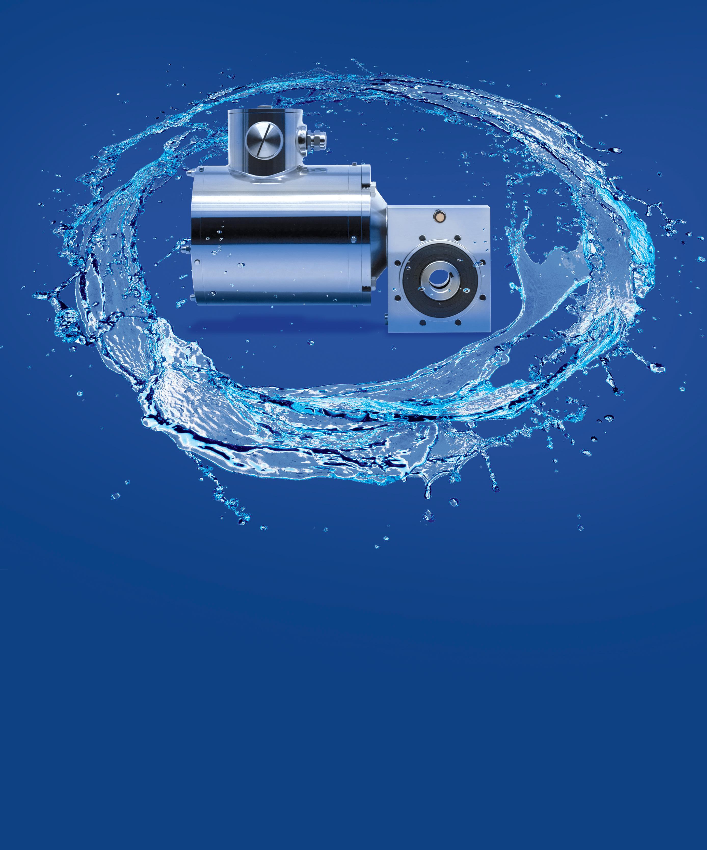
www.bodine-electric.com | info@bodine-electric.com | Northfield, IL USA | 773.478.3515 (USA) RATED SPEED TORQUE GEAR RATIO VOLTAGES 29 to 176 rpm 158 to 638 lb-in 10:1 to 60:1 230/460 VAC
Powered by an AC inverter-duty motor with stainless steel, corrosion resistant housing, our new IP-69K rated hollow shaft gearmotors are fully watertight and can withstand rigorous daily washdowns. These geared motors deliver maintenance-free performance where standard gearmotors can’t survive.
Just like the nervous systems of animals, motion controllers can work to command systems arranged for:
• Centralized control (like the human body) with most all components networking back to the main controller
• Distributed control systems using (like the diffuse neurological structures in an octopus) engineered cabling and electronics integrated into axis components to execute logic at the periphery.
Widely employed in industry are both control architectures as well as their advanced motion controllers — especially those operating in precision steppermotor systems and servomotor systems with various levels of feedback. The latter process input commands, compare those with motor feedback signals, and execute corrective computations to make the axis positions or motions track the controller commands … with reasonably fast communications (with 1 msec to 200 μsec being typical) and little to no error.
Supreme are motion profiles — the mathematically defined trajectories that motion controllers command axis driveand-motor systems to follow. Many motion profiles define sequences of position commands over time to tell the axis how and where to position attached load. Here, motion-controller electronics also convert created trajectories to generate torque commands to be used by the drive powering the motor.
Key are motion profiles and how they dictate the motion-controller hardware and software that’s most suitable. Also key are the function and applicability of standalone controllers that mount on or in machines; controllers that tightly integrate into primary host controls (on machines or in control panels on DIN rails); hybrid components combining controls and human-machine interfaces; the broad category of PC-based motion controllers; and the various electronics and networks involved in motion controls.
It’s true that engineers too young to have had personal experience with historical control technologies may be confused by today’s disparate range of motion programming and hardware options. After all, most any modern processor (especially those in industrial
PCs or IPCs) can perform CNC, motion, PLC, and DCS functions. The real design challenge is choosing the hardware and software that makes the most sense for a given motion design — even though various controls serve what are essentially the same functions.
In short, motion controllers are differentiated by their programming and the way in which they integrate into and function for specific applications.
Two converging tracks in motionsystem history
Except perhaps for the well-defined standards of the National Electrical Manufacturers Association (NEMA) for step motors, there are few consistent naming conventions for product types in motion-control and discrete-automation industries. So instead of a standard, engineers will often refer to the maker of a given component to describe an arrangement — as in a Kollmorgen servomotor or Parker servomotor or a Siemens servomotor, for example — though it’s rare that they’re exactly equivalent products. European suppliers do follow IEC guidelines but not strictly so, as a servomotor (to continue with that example) might have IEC-standard mounting but shaft with supplier-specific dimensions.
Such terminology inconsistency applies to motion controllers as well. Here it’s helpful to remember that decades ago, motion design involved two separate (but slowly converging) disciplines — one discipline called motor control and another discipline called motion control.
Choosing a motion controller
Various design objectives and requirements dictate which motion controllers and control architecture are most suitable for an application. To fully specify a control system, engineers must decide on control hardware, how controls will integrate with motors and drives, and whether industrial-network connectivity will be required.
Letting the application dictate the motion-controller choice avoids problems associated with choosing controllers that are simply most familiar to the engineering team or OEM. It also avoids
excessively costly motion controllers that may be overkill for the design at hand. General-purpose control hardware leveraging modular designs, standardized physical connections, and software compatible with open-source or universal code should be chosen where practical. Where a machine is expected to support IIoT functions, the motion controller should work with running machine logic as well as data collection.
Sometimes least conducive to expanding a machine’s functions (as requirements become more sophisticated over time) are controls based on motioncontroller boards designed for a finite number of axes and (ironically) traditional PLCs emphasizing I/O. As with all design engineering, it’s prudent to prioritize the scalability of a motion-control system over any immediate short-term profitability objective or impulse to specify the most familiar or least expensive controller solution. That’s especially true for integrators and OEMs having decades-long relationships with end users expecting operations evolve over time.
Yet another design parameter to consider when specifying a motion controller is the intended installation location — whether in a control panel, on a machine frame, or in a motor. Here, space constraints can preclude certain choices and architectures — especially where cabling and connectivity restrictions necessitate the tight grouping of motion components.
Perhaps the most important design parameters though are the design’s power requirements and required level of motion sophistication. Following are descriptions for three complexity classes — simple, moderate, and fully-coordinated motion control. Though there’s overlap between these artificially drawn classes (as well as their motion requirements and technologies) it’s still helpful to consider their distinctions.
Simple motion control: The simplest motion-control systems run axes through indexing and point-to-point positioning routines. Indexing involves velocity or position control sans acceleration control — so only allows some speeds and motion profiles. Unsurprisingly, controllers for these designs are cost-effective variations
21 DESIGN WORLD — MOTION 8 • 2023 motioncontroltips.com | designworldonline.com controllers
with modest and focused capabilities.
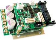
Component-type (box) variations include either buttons or (more advanced) communication ports for programing and connecting encoders and feedback; capabilities are set, and configuration is often through the supplier’s own software. Offering more flexibility are board-format controllers boards (without or more often with motor drives onboard) in standard commercial off the shelf (CotS) and custom versions. The latter are designed by large OEMs imparting some build with simple motion and aiming to keep cost and weight down. After all customized boards avoid inclusion of extraneous capabilities or connections. They also allow for small and rugged formats to directly mount into products or machines sans any tether to a control panel.
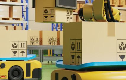
Moderate motion control: These midrange designs include single-axis motordriven products needing somewhat more sophisticated motion as well as multi-axis machines that need no or little inter-axis coordination. Stages and gantries for materialtransfer operations are a couple examples; others include those in discrete parthandling operations; large-scale automated warehousing; and smaller machinery in packaging and general automation.
Systems based solely on PLCs excel at commanding such motion, especially when an installation involves independent single axes. OEM-designed or CotS motion-controller circuit boards are also common, especially on mobile designs. Still other common technologies for moderate motion-control
applications such laboratory-automation equipment are those supporting basic forms distributed control. These include smart motors having onboard drive+controller electronics for partially coordinated machine axes. If such a motor integrates into a PLC-controlled design, its electronics can operate with digital handshakes to the PLC. Runs, stop inputs, and busy signals from the motor control electronics can often suffice. Applications needing more coordination or speedier moves don’t run well off PLC-based systems as performance can be limited.
Advanced (fully coordinated) motion control: These include demanding motion designs involving material slicing, trimming,
Motion controllers include PC-based controllers and microcontrollers. The application dictates which is most suitable.
shaping, machining, welding, and assembling, and anything else needing interpolated multiaxis motion. Other applications in this class include those involving imaging (especially medical imaging) and precision high-speed conveyance and positioning of delicate workpieces into workstations.
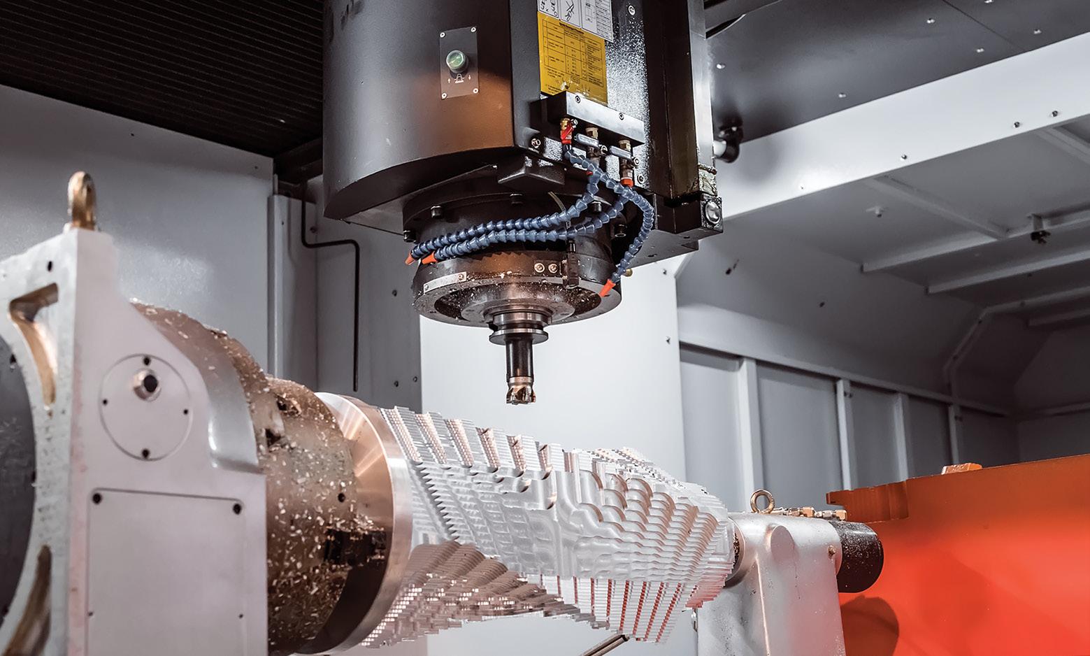
Machine designs running such operations necessitate specialized software to coordinate all axes with position and speed commands doled out at rates to dozens of kHz. They also necessitate motion controllers having sufficient processing power and connectivity to command adjustable motor speeds and travel limits; homing routines; multi-axis interpolated moves; coordinated high-speed multi-axis actions; and even actions for emergency stops.
Here common hardware includes networkable drive+controller boards as well as IPCs or PACs with high bandwidth on parallel electrical connections called backplanes for motion-data sharing between modules and systems. High-bandwidth backplanes allow full use of processor cores for complex axis-to-axis coordination — even in demanding machine tool and robotic installations.
Automated machinery for pharmaceutical manufacture also tends to employ such hardware for centralized and deterministic motion controls. In contrast, distributed architectures for fully coordinated multi-axis control rely more heavily on computationally powerful drive+controller boards.
22 DESIGN WORLD — MOTION 8 • 2023 motioncontroltips.com | designworldonline.com montion control handbook
Precision multi-axis motion demanding high throughput is the ultimate motion-controller challenge. Image: Shutterstock
Better Performance. Smarter Motion.
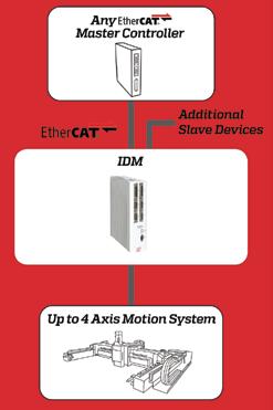

advanced semiconductor, electronics, or display manufacturing equipment? Challenge us with your high-performance OEM motion control application! www.acsmotioncontrol.com Meet the Intelligent Drive Module (IDM) Seriesdrives designed to maximize high-precision motion stage performance in high-tech manufacturing equipment.
Advanced servo control algorithms and performance optimization tools
High-frequency position-based I/O for device triggering and data capture
Single- and multi-axis models for single- and multi-axis stages
Designing
•
•
•
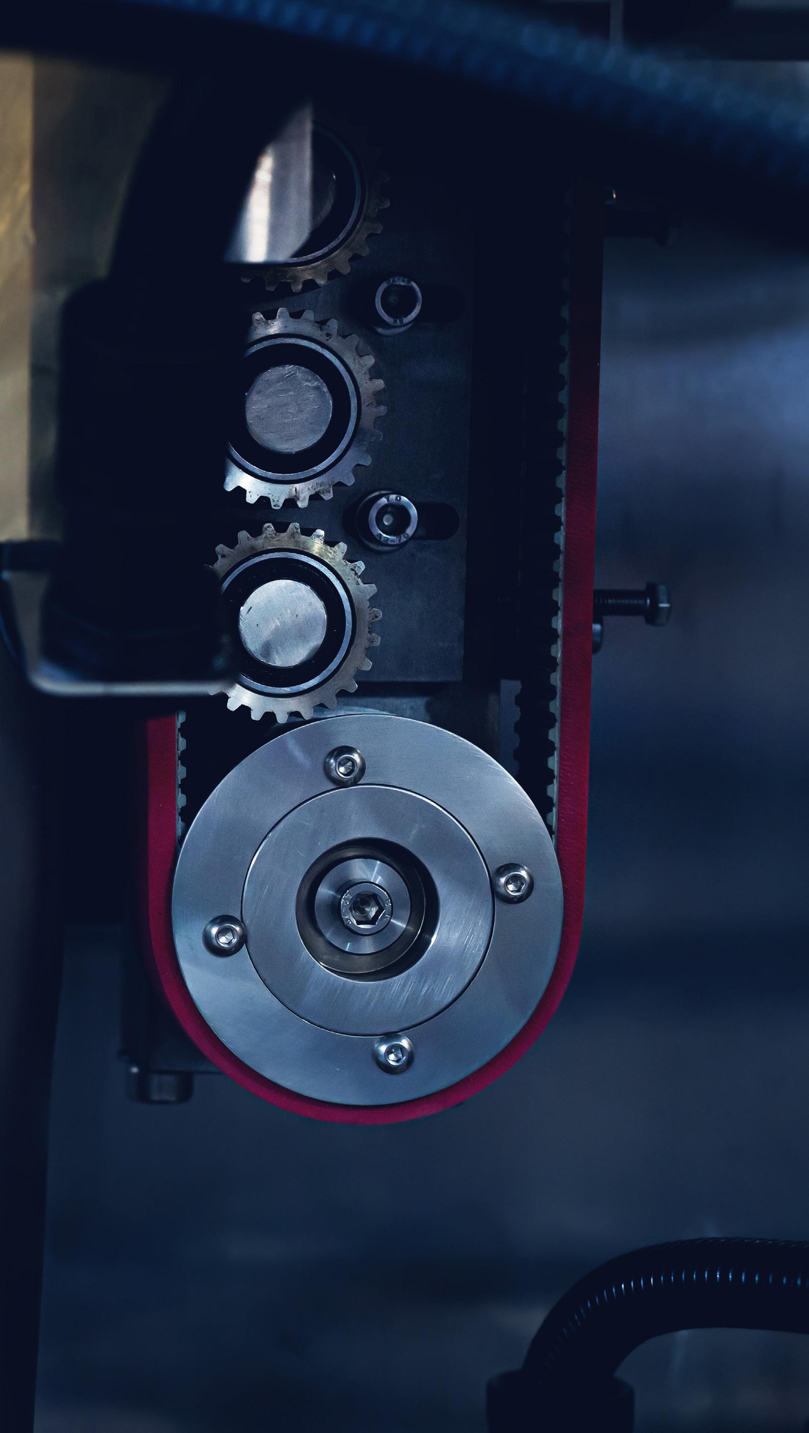
SIZING PULLEYS FOR SYNCHRONOUS BELT DRIVES
A belt and pulley system is a tried and true method of implementing a basic motion system.
24 DESIGN WORLD — MOTION 8 • 2023 motioncontroltips.com | designworldonline.com motion control handbook
belts & pulleys
Such belt drive systems used in industrial applications consist of rubber belts that wrap around drive pulleys, which are typically driven by an electric motor. Belts may also wrap around one or more idler pulleys that keep the belt taut and on track.
Design engineers use belt and pulley drives because they require little if any maintenance, they’re less expensive than chain drives, and they are quiet and efficient, up to 95% or more. What’s more, the tensile members of the belts used today — cords embedded into the belt rubber that carry the majority of the belt load—are stronger than ever. They’re made of a number of materials including polyester, aramid, fiberglass, or carbon fiber.
As for pulleys, most are made from either metal or plastic. The most suitable type for an application depends on a host of factors including the required precision, price, inertia, and magnetic properties, among others. Sometimes, plastic pulleys with metal inserts or metal hubs are a good compromise.
Basics of pulley sizing
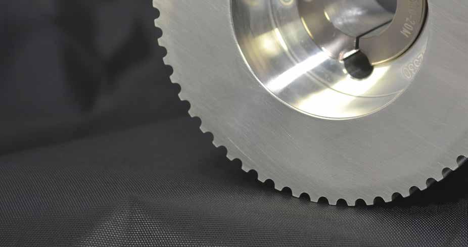
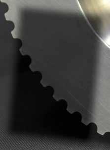
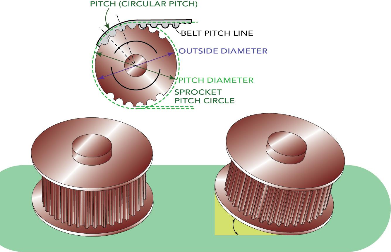
When designing a belt drive system, the first step is to choose the most suitable belt for the application. But the pulleys also play an important role in the performance of the belt — especially in synchronous belt drive systems, where proper meshing of the belt teeth with the pulley grooves can affect everything from the amount of torque that can be transmitted to the belt’s rate of wear and potential failure modes.
Synchronous belt and timing pulleys are typically designated by the number of grooves (analogous to the number of teeth on the belt), groove pitch (analogous to the belt tooth pitch), and pulley width.
The required tooth pitch (and, therefore, groove pitch) is determined during belt selection, based on the design torque and speed. Torque and speed are also the primary factors in determining belt width, and therefore pulley width. (Recommended pulley width is typically slightly larger than the belt width and takes into account the space required for pulley flanges.) The number of pulley grooves is determined by the required speed ratio.
Dimensional information also includes the type and size of hub for attaching the pulley to the drive shaft. Common options for pulley mounting include taper lock bushings, split taper bushings, QD (quick disconnect) bushings, or plain bores with or without keyways.
Although pulley diameter isn’t explicitly specified during selection, it can be determined by the number of pulley grooves and their pitch, which are used to calculate the pitch diameter of the pulley. The pitch
gearing
25 DESIGN WORLD — MOTION 8 • 2023 motioncontroltips.com | designworldonline.com
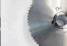
Precision pulleys maintain the accuracy of synchronous belt drives. Image: Iankovskii Ian • Dreamstime


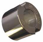


Custom Machine & Tool Co., Inc. 800-355-5949 sales@cmtco.com www.cmtco.com Precise. Reliable. Trusted. Concentric Maxi Torque American Engineering | American Made © Custom Machine & Tool Co., Inc. Manufacturers of Power Transmission and Motion Control Components Our keyless hub-to-shaft connection device has superior features and benefits compared to other connection systems such as keyways, pins, set screws, clamp collars, and other tapered shaft locking devices. Email or call to get your CMT Stock Products Catalog. Order today. Ships today! Manufacturers of Power Transmission and Motion Control Components Custom Machine & Tool Co., Inc. 301 Winter Street P.O. Box 298 Hanover, MA 02339 tel (800) 355-5949 (781) 924-1003 fax (800) 355-4490 (781) 924-5154 sales@cmtco.comwww.cmtco.com Synchronous Timing Pulleys Featuring Concentric Maxi Torque, CMT’s Patented Keyless Hub to Shaft Connection System Stock Product Catalog Order Today • Ships Today Precise. Reliable. Trusted. American Engineering • American Made Synchronous Timing Pulleys ConcentricFeaturing Maxi Torque Bushing System Stock Product Catalog Order Today • Ships Today Precise. Reliable. Trusted. Manufacturers of Power Transmission and Motion Control Components
diameter is slightly larger than the outer diameter of the pulley and corresponds to the pitch line of the belt, which is the line formed by the belt’s tensile cord.
Pulleys for synchronous belt equation:
Where pd = Pulley pitch diameter (mm)
P = Pulley groove pitch or belt tooth pitch (mm)
N = Number of pulley grooves
Once the pitch diameter is calculated, the pulley’s outer diameter can be determined by finding the distance from the belt pitch line to the bottom of the tooth profile (a value specified by the belt manufacturer), and subtracting twice that distance from the pulley pitch diameter.
For pulleys to mate with synchronous belting:
Where O.D. = Pulley outer diameter (mm)
U = Distance from belt pitch line to tooth profile bottom (mm)
Some manufacturers offer pulleys in the form of bar stock to be cut and machined by the end user. While this can be an economical solution for prototyping small quantities, the accuracy of the pulley is critical to ensure proper belt tracking, speed ratio, and efficiency.

Acceptable pulley tolerances are specified by trade associations such as the Mechanical Power Transmission Association or MPTA and the International Standards
Longer Lasting Belts & Pulleys
Better than Lifetime Warranty
We use 100% virgin urethane (no regrind waste). Makes stronger, longer lasting belts.
« Abuse Resistant Belts work where others fail.
« Super Strong Joints are virtually unbreakable.
« High Tension Belts move heavier loads.
« HEHT black belts double capacity.
« Low cost, highly efficient, elastic flat belts.
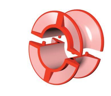
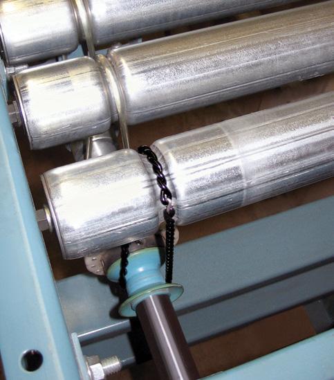
Split Line-shaft Spools
l High precision. Reasonable price.
l Easy to install. Zero downtime.
Round, Flat, Vee and Poly-V Belts and Pulleys
Top: Here is a typical belt and pulley configuration showing a few key parameters. Bottom: Angular misalignment of pulleys can cause belts to track to one side.
27 DESIGN WORLD — MOTION pd =
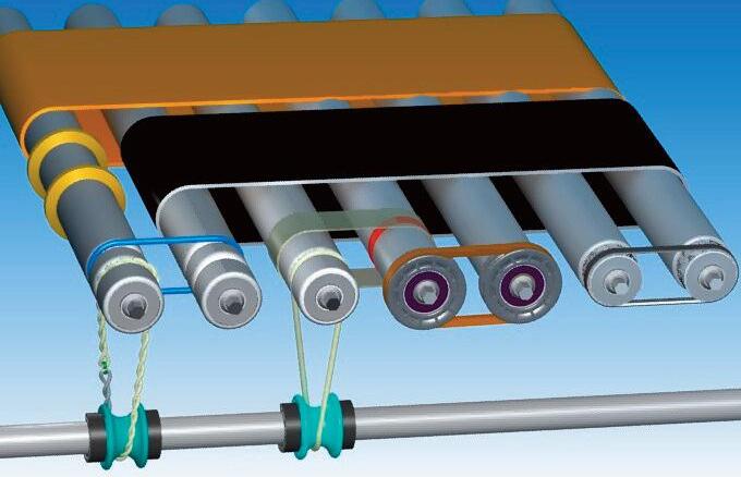
Although the focus of this article is synchronous (toothed) belts, flat belts also find copious use on roller conveyors. To be clear, many of the latter integrate synchronous motors. Image: Dreamstime
Dura-Belt 800-770-2358 614-777-0295 Fax: 614-777-9448 www.durabelt.com
Longer lasting Belts, HEHT Split
-- no regrind wide_Layout 1 7/12/2023 3:10 PM
8 • 2023
Spools
belts & pulleys
Manufacturing Precision Gears, Mechanical Components, and Custom Drive Assemblies for the Aerospace, Medical, and Automation Industries Stock and Custom – One Single Source Engineering and Manufacturing Partner to OEMs Worldwide Prototype to High-Volume Production Gears & Gearboxes Timing Belts & Pulleys Couplings Miniature Gearheads Planetary Gearheads Shafting and Shaft Accessories Subassemblies for Integration into Larger Systems Est. 1950 ISO 9001 + AS9100 ITAR Compliant-DDTC Registered NIST SP 800-171 RoHS and REACH DFARS compliant components as required We have the know-how, state-of-the art manufacturing facility, and CNC machinery you need! Call Us at 516-328-3300 or Shop SDP/SI at www.sdp-si.com
belts & pulleys
Organization or ISO. In some cases, major belt manufacturers also specify tolerances for specific tooth profiles.
Key manufacturing tolerances for synchronous belt pulleys include:


• Pulley outer diameter
• Eccentricity between pulley bore and pulley outer diameter
• Parallelism between pulley bore and vertical pulley faces
• Pitch accuracy of grooves
• Parallelism between grooves and bore


Pulleys may also need to undergo static or dynamic balancing after manufacturing.

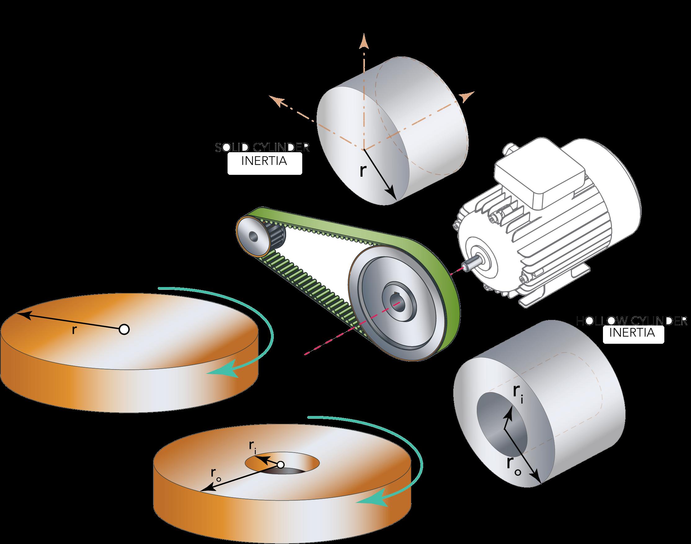
Synchronous belt pulleys can be made from a wide range of materials, including aluminum, steel, cast iron, and various plastics. The material of the pulley determines its weight and inertia, and so affects the dynamic performance of the belt drive system. Material selection also influences the amount of noise generated by the system, with polycarbonate (thermoplastic polymer) pulleys generating more noise during operation than metal pulleys.
To prevent the belt from riding off the pulley, and to resist the lateral forces caused by the belt’s side-toside motion, synchronous belt drives typically require flanged pulleys. In general, manufacturers recommend that synchronous belt systems include at least one pulley with flanges, although there are some exceptions to these guidelines.
Note on belt trends
Recent years have seen convergence of specialty belt drive systems in mass-produced consumer and light industrial tools with the standard belt drives integrated into specialty machine designs. That’s because options have proliferated for belts with flat and round profiles as well as those with various V-shaped profiles and toothed belts for synchronous operation. The Association for Rubber Products Manufacturers (ARPM) originating from the Rubber Manufacturers Association (RMA) and the National Industrial Belting Association (NIBA) along with component suppliers dictate the details of how the geometries and performance of these industrial belt drives are standardized and quantified.
load, it must overcome the load’s inertia or resistance to change in motion, as explained in Newton’s First Law. In synchronous belt-driven systems, the motor must overcome not only the inertia of the applied load but also the inertia of the belt, pulleys, and motor coupling.
LINE SHAFT CONVEYOR BELTS Original Equipment and Connectable CUSTOM MADE IN INCH, METRIC & O-RING SIZES • Round, Flat and Connectable Polyurethane Belts • Very Clean Operation • Eliminates Tensioning Devices • Exceptional Abrasion Resistancexxxxxxxxxxxxxx pyramidbelts.com POWER TRANSMISSION-PART CONVEYING PYRATHANE® BELTS Lifetime Warranty Against Manufacturing Defects AN ISO 9001 CERTIFIED COMPANY 641.792.2405 sales@pyramidbelts.com 19Pyramid_4x475_PC.indd 1 12/4/2018 4:56:13 PM
29 DESIGN WORLD — MOTION 8 • 2023
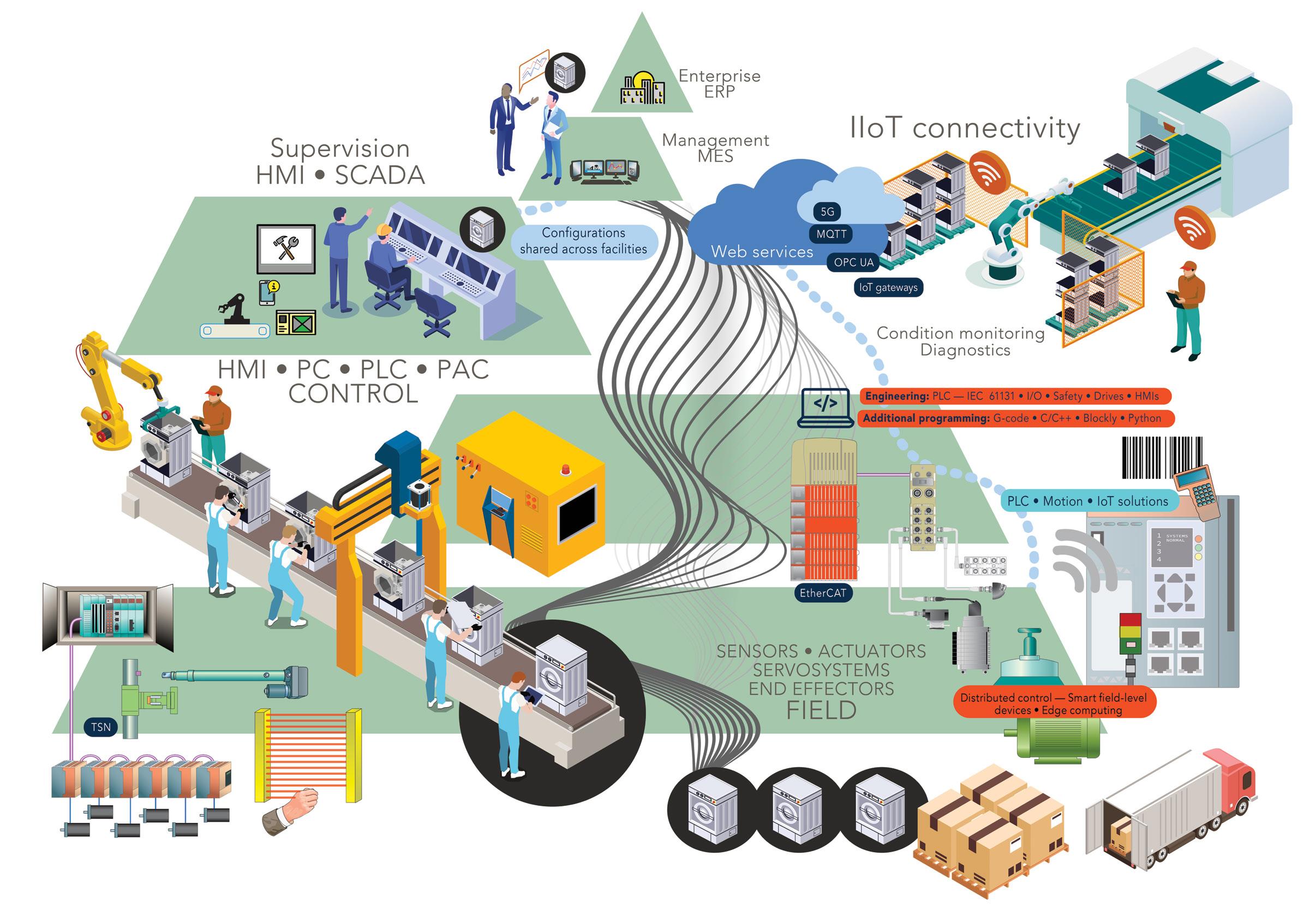
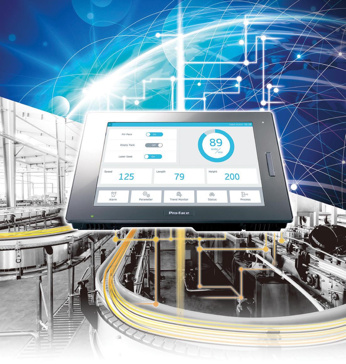
MACHINE CONNECTIVITY UPDATE
Smart factories are facilities that digitize all aspects of manufacturing or production that allow digitization. Such operations continuously record data via connected equipment and systems — and then disseminate that data to allow machines to run self-optimizing routines.
Such programs might help the facility time production of a given end product; proactively prevent mechanical issues; and streamline interconnected manufacturing tasks. Comprehensive approaches to building smart factories leverage cloud tools, AI, IIoT, and big data analytics for monitoring supply-chain forecasts and triggering (increasingly adaptable) production lines to respond.

motion control handbook
30 DESIGN WORLD — MOTION 8 • 2023 motioncontroltips.com | designworldonline.com
Networks underpinning smart-factory functions
Let’s now get into the specifics of smart-factory connectivity. Industrial protocols supporting smart-factory functions usually require certification of physical components … including cables, controllers, and feedback devices. Consider CAT5e and CAT6 Ethernet cables. 802.3 (1 Gbit/sec or GbE) Ethernet can use Cat5a or increasingly common Cat6 cables supporting Power over Ethernet (PoE) increasingly common in automated machines and robotics. Elsewhere, flexible CAT5e and CAT6 cables support CC-Link Industrial Ethernet (IE) networks and come in cable-carrier-bundled assemblies sporting UL certification for North American markets. They also sport the certificate for CC-Link IE protocols so common in Asia and growing around the world. Such cables can make connections between control, device, and sensor-level components via CCLink variations for these network levels … with all commanded by an industrial computer.
Consider one class of such computers —industrial controllers supporting the CC-Link IE Field industrial network (again, one of several in the CC-Link protocol family) and allowing data exchanges to 1 msec for realtime equipment control. Some such controllers also leverage the network for data computing, remote monitoring, edge computing, and the integration of hardware and software. It’s typical that these controllers have a form Windows 10 IoT installed, though the operating system VxWorks as well as open-platform Edgecross can also be used to process and distribute data. Some such industrial computers even include touchscreens to double as human-machine interfaces (HMIs).
Elsewhere, HMIs might do double-duty as gateways … and many motion-component manufacturers offer network gateways and cable sets to enable connections of their linear actuators and other devices to CC-Link. For example, the gateways might convert data from a host CC-Link communication protocol to the component suppliers’ own RS-485 communication protocols. Such gateways (and those more sophisticated) make it easy to integrate and control RS485-connected components under the host communication environment.
Even beyond the enduring standards of serial interfaces and the burgeoning forms of Ethernet connectivity, other cable and communication standardization is simplifying sophisticated communication between components on a given network level. Consider the migration to single-cable solutions for servodrives and motors: HIPERFACE DSL is one servocontrol feedback interface using single-cable technology. Fully digital two-wire communication supports operating communications as well as condition monitoring of servo axes. The main benefit of HIPERFACE DSL is how it allows the routing of motor power and position feedback through one cable — in turn trimming complexity and cost. Plus smart HIPERFACE DSL encoders include internal memory to store motor information … so upon initial connection, a servodrive can query this information to help automate motor commissioning.
In the same way, single-cable solutions based on Ethernet or even digital subscriber line (DSL) cables improve machinery
cables & connectivity
Smart factories maximize the use of digital tools.
Image: Phuttaphat Tipsana
31 DESIGN WORLD — MOTION 8 • 2023 motioncontroltips.com | designworldonline.com
incorporating linear actuators — often offering compatibility with amplifiers from various manufacturers for quick and seamless controller to actuator integration.
Another single-cable solution on the rise is IO-Link — that branded standard of IEC 61131-9 defining a simplified system for actuator and sensor connectivity. In fact, the number IO-Link-capable devices could double every year through 2023 as end users and OEMs aim to leverage the expanding suite of IO-Link functions. Some intelligent-motor suppliers have begun to integrate IOLink primaries into the core offerings for supporting connectable sensors for decentralized automation concepts. Of course, motors that can communicate via industrial Ethernet or CAN bus don’t need to connect to IO-Link networks as secondaries.
IO-Link can also digitize legacy analog connectors on linear actuators to impart bidirectional communications and quicker commission times. No wonder some have adopted IO-Link connectivity on the controls side for multi-protocol support and connection with serial interfaces.
Protocols and cloud connectivity serve smart-factory functions
Consider the various protocols and communications leveraged in IIoT connectivity — for example, SCADA, MES, and enterprise resource planning (ERP) architectures. These are the most involved in IT/OT (operational technology) convergence — often
involving enterprise-level tasks, gateways, and other connectivity to allow system configuration through standard web browsers … as well as operational adjustments and additional managerial actions. To be clear, comprehensive SCADA installations (despite their complexity and considerable installation requirements) excel at big-data capture and processing; maintenance and use of historical data; and execution of analytics routines. However, smart-factory solutions allow faster setup of remote-access networks, edgecomputing systems, and central or on-machine (HMI) control over pertinent machine settings and data.
Employed in many IIoT installations is Structured Query Language (SQL) — programming that allows synchronization of data and event logs to MySQL and MS SQL database servers. The benefit here is IT personnel access that’s more simply implemented than alternatives relying on controls. That’s true whether the systems employ basic controls such as Raspberry Pis or complex PC-based IoT database interfaces (which usually necessitate additional hardware and software).
Also seeing massive adoption for how they support multipronged IIoT design approaches (involving software, hardware, and connectivity) are infrastructure, platform, and software as a service (IaaS, PaaS, and SaaS respectively) or cloud services. These include Alibaba Cloud, Tencent Cloud, Google Cloud, IBM Cloud, and Oracle Cloud. However, in the U.S., today’s two leading public (offsite not company or machine network) cloud service providers
motion control handbook
32 DESIGN WORLD — MOTION 8 • 2023 motioncontroltips.com | designworldonline.com
Smart factories are dominated by components and equipment with fieldbus, wired Ethernet, wireless, and cloud connectivity.


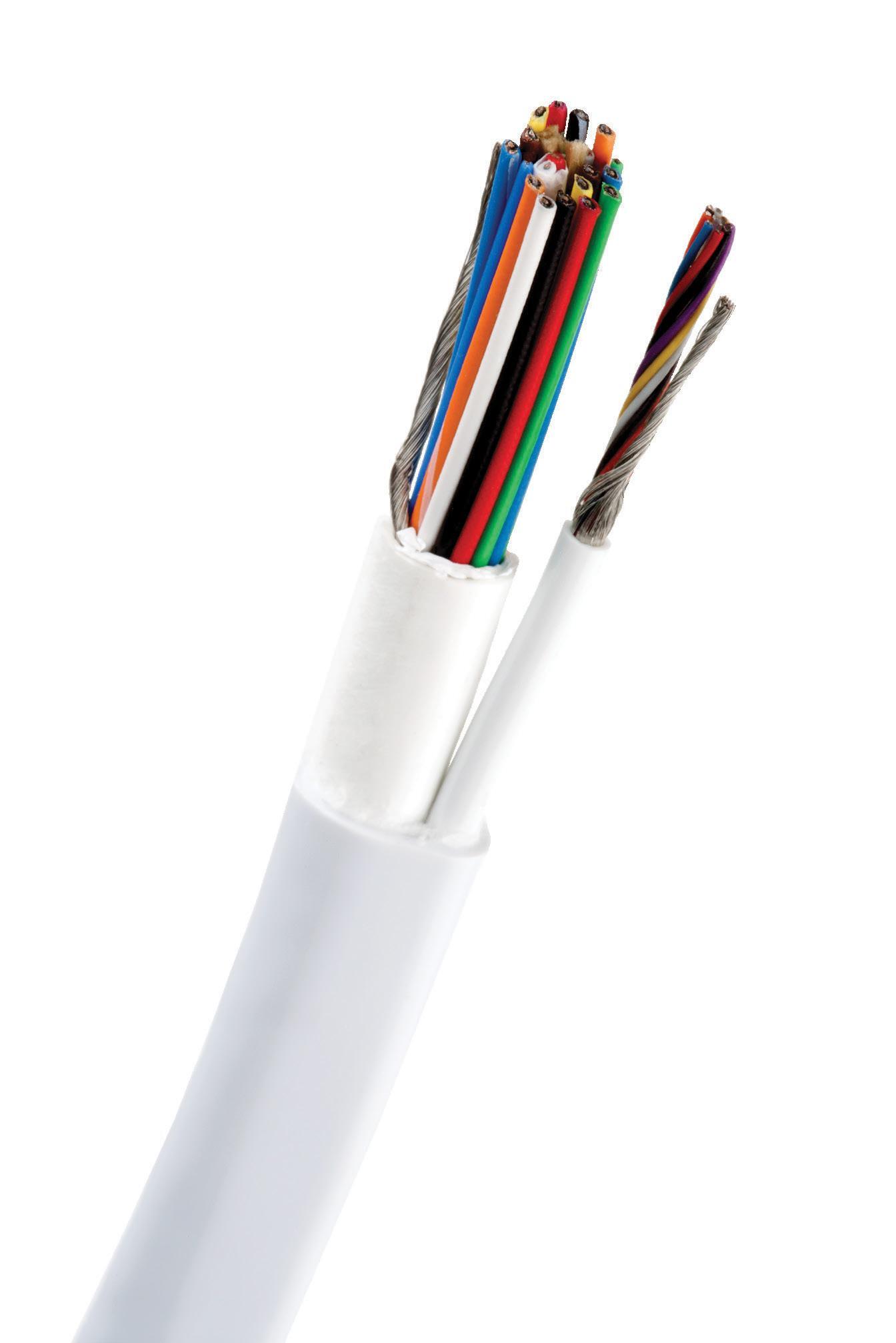
Manufacturing Custom Wire & Cable Solutions Since 1898 603-838-6624 • newenglandwire.com Lisbon, New Hampshire USA Since 1898, we have partnered with the most innovative companies in the world to solve complex challenges and advance technology. Our legacy of decades of expertise and unrivaled reliability makes us the industry leader in custom wire and cable solutions.
for machine automation are:
• Amazon Web Services Inc. with AWS cloud software and services
• Microsoft with Azure IoT Edge cloud software and services
Such cloud services primarily support the use of databases (through products such as Amazon simple storage service or S3 buckets and Amazon DynamoDB managed database services), online and local applications, and on-demand computational power. Related to the latter are AWS Lambda services that allow Python, Node.js, Java, and C# programming to run on the service’s servers. HMIs let end users make the most of these IIoT functions.
Of course, cloud services serve other functions too. Part of what’s driving AWS and Azure adoption for IIoT is how more engineers have become comfortable with building out their own infrastructure on these platforms. After all, cloud-based data services free engineers from extra design work on underlying hardware and software — because the provider executes IT tasks. AWS and Azure also allow use of software that abstracts dataflows and communications — simplifying some design work with development environments having attractive GUIs to shield engineers from dealing with programming minutia.
Cloud services also facilitate advanced engineering with virtual machines that run operating systems and applications … over which design engineers maintain control. What’s more, cloud services can accommodate various communication services on protocols employing publish-subscribe principles — to be the master service for them all. That eliminates the need for time-consuming addressing during system setup. All such features can facilitate advanced capabilities including machine learning for categorizing and distilling data … and making predictions to prompt machine and production adjustments.
A related trend is increased use of precurated cloud portals from suppliers. These portals (which give engineers a simple way get started with IIoT) are online services that connect with users’ controllers and touchscreen HMIs. Then engineers can customize HMI screens and dashboards with trends … and configure HMI email notifications using a rule engine managed from the cloud portal. The list of functions goes on. Some arrangements allow remote software updates on the components — and remote viewing of the components’ web visualizations.
Touchscreen HMIs and controllers certified
for AWS GreenGrass Core essentially leverage AWS (including AWS Lambda and Things Graph) to let connected edge devices (such as sensors and actuators) locally act on data they generate — and use the cloud for data management, storage, and analytics. With AWS IoT Greengrass, connected devices can also run Docker containers of the containerization service from Docker Inc.
Recall that in the context of industrial programming, a container is a piece of executable software that holds the codes, system tools, runtimes, libraries, and settings needed for the standalone running of an application. In many machine designs, containers are designed to communicate and synchronize data to other systems or execute various predictions — even when disconnected from the internet. Advantages of building applications in containers include:
• Easy deployment onto devices
• Portability of software to allow its use across different platforms
• Improved security by providing a sandbox for engineers’ applications

Some HMIs and DIN-rail-mountable controllers accept installation of Docker … and in fact, some suppliers regularly release prebuilt containers to extend services onto these products.
Anywhere an HMI connects to the cloud, it’s likely working in some IIoT capacity to inform corporate analytics and continual operations improvements. That’s true of automated installations involving one to hundreds of machines. Protocols supporting IIoT functions including various forms of data communications and HMI connectivity with edge devices include:
• Open Platform Communication Unified Architecture or OPC UA
• Representational State Transfer or REST and its application programming interfaces (APIs)
• The advanced message queuing protocol or AMQP
• Message queuing telemetry transport or MQTT
MQTT — so core to many IoT connectivity structures — is a protocol supporting scalable communications between sensors and mobile devices. Any built-in device support for MQTT is useful because it’s applicable in Amazon AWS IoT services. In addition, MQTT (like AMQP) is lean and standardized … and MQTT can be implemented on gateway HMIs handling fielddevice data for onsite and cloud systems. HMIs offering the most MQTT support are meant to be connected to value-added services for provisioning data that’s been edge processed in third-party
34 DESIGN WORLD — MOTION 8 • 2023 motion control handbook
Image: Adobe Stock
HELUKABEL is a global cable system solutions provider specializing in the production of cables, wires, cable assemblies, robotic dress packs, and drag chains. Our electrical solutions consistently and reliably bring power and transmit data to our customer’s applications in various automation-focused industries including machine building, automotive manufacturing, material handling, food and beverage, wood, pulp, and paper processing, oil and gas, and robotics.
With a comprehensive product portfolio of more than 33,000 stock items, and the capabilities to design and build custom solutions, HELUKABEL is your one-stop source for electrical connection technology.


HELUKABEL® USA, Inc. | West Dundee, IL | www.helukabel.com | sales@helukabel.com
systems — and run off cloud services. Such HMIs can connect as a MQTT publisher (and send messages to a broker) or a subscriber (and request messages from a broker) or a broker (and manage data and connections with publishers or subscribers).


Interoperability standard OPC UA is also indispensable for leveraging the full promise of connected HMI technology. OPC UA includes publish-subscribe communications in its specification definitions, so can serve as an alternative to MQTT for data transport to the cloud. Those in motion control most value the standardized communication protocol of OPC UA complemented by time-sensitive networking (TSN) as a vendor-independent fieldbus for decentralized automation. OPC UA with TSN can even render additional PLCs unnecessary — as in machines employing integrated servomotors, for example. After all, more systems than ever now benefit from distributed architectures incorporating smart motors and other components capable of processing commands and executing tasks (motion and other) while communicating with other devices in realtime. In some cases, the latter can include HMIs serving as edge gateways to handle some of the axes’ process logic (as well as connections to ERP systems and the cloud).
Example of how HMIs use MySQL database connectivity


Employed in many IIoT installations is structured query language (SQL) — programming that allows synchronization of and access

to data and event logs on MySQL and Microsoft SQL (MSSQL) database servers. This relational database management system is free, open source, and widely supported. It’s also secure — so safely integrated into controller HMIs and panel PCs. One SQL benefit is IT personnel access that’s more simply implemented than alternatives relying on controls (and usually necessitating additional hardware and software). That’s true of system controls as simple as Raspberry Pis or as complex as PACs with IoT database interfaces.
In fact, SQL also works with some controller HMIs that collect and display machine data for easier monitoring and analytics. For example, connecting such HMIs to a MySQL database allows data collection, organization, and storage in flexible and trusted databases for easy access and optimized business operations. Some supplier design software helps engineers use MySQL via smart HMIs and put data in Excel spreadsheets (and tabular data in the files of other common software) to:
• Display information on the HMI screen


• Synchronize data and event logs to a remote MySQL server on the local network
• Manage that data on the server. Then engineers can use MySQL and MS Excel to collect, analyze, and respond to the data for more informed decisions and optimized operations.

encoders for position and motion control

36 DESIGN WORLD — MOTION 8 • 2023 motion control handbook
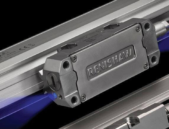
Powerfully positioned for innovative motion control. Your partner for innovative manufacturing www.renishaw.com/encoders usa@renishaw.com Renishaw Inc., West Dundee, IL 60118 © 2022 Renishaw Inc. All rights reserved.
Superior
With a comprehensive line up of encoder solutions, Renishaw brings the expertise needed to address your manufacturing challenges. Whether your application calls for optical, magnetic or laser technology, our encoders achieve the highest levels of accuracy, durability and reliability.
MOTION CONTROL
DESIGN GUIDES
Key technology content produced by the editors of Design World compiled in individual design guides. Collect these free technical PDFs!
GEARMOTORS
HUMAN-MACHINE INTERFACES (HMIS) COUPLINGS

Find these and additional guides in our DESIGN GUIDE LIBRARY, bookmark this site as guides are added on an ongoing basis! designworldonline.com/design-guide-library
SERVOMOTORS

 BROUGHT TO YOU BY:
Cleanable conveyance surfaces are indispensable in automated food production. Image: Dreamstime • Gumpanat Thavankitdumrong

COMPARING CONVEYOR OPTIONS
Most conveyors in light to medium-duty discrete-transport applications (as in conveyors for retail, off-highway, consumer-grade exercise equipment, and office machines) use the thin synthetic belt — that relatively flat fabric-based medium that wraps around two or more pulleys. An electric motor powers these pulleys that in turn have geometry specialized for the reliable advancement of the conveyor belt.
38 DESIGN WORLD — MOTION 8 • 2023 motioncontroltips.com | designworldonline.com
Styles and materials abound to meet specific applications. Monofilament construction (whether in endless or spliced variations) imparts high tensile strength, strength, and flexibility.


Perhaps confusingly, belts using friction with their pulleys for advancement can be classified as low friction. Note that this designation actually indicates that the top of the belt (on which articles ride) allows product to slide a bit for accumulation at stations. In contrast, high-friction belts have more grip on their product-facing surface to better hold products to the belt for predictable advancement.
In fact, engineers often customize these conveyors in other ways to meet exact application specifications.


Magnetic conveyors are built with ceramic magnets for applications that need parts to adhere to the belt during processing, or for jobs that require elevation changes. Engineers can specify higher magnet strength for use in inverted applications.

On some legacy designs, centering polymer tracking guides (usually V guides) molded into or welded onto the belt mate with a matching channel in the conveyor bedplate or frame. This feature can prevent the belt from laterally tracking to one side or the other. Note that most manufacturers recommend other solutions to pre-vent tracking issues.

The engineered fabric belt on some conveyors is perforated to support vacuum conveyor functions. The conveyor frame features a sealed bedplate section that’s fitted with a pump; belt perforations over this section draw air to hold light or flimsy parts on the conveyor belt — even on inclines or during fast transport.
Metal-free conveyors have Delrin bedplates instead of the traditional steel bedplate under sections to complement metal-scanning equipment checking food or other conveyed product for metal shavings. (Delrin is an inflexible polymer that works as a tough heat-resistant metal substitute.) Upon the detection of metal contaminant, a retractable tail conveyor or other reject mechanism allows the discard of affected product.
Pivot conveyors mount to a pivot base
conveyors 39 DESIGN WORLD — MOTION
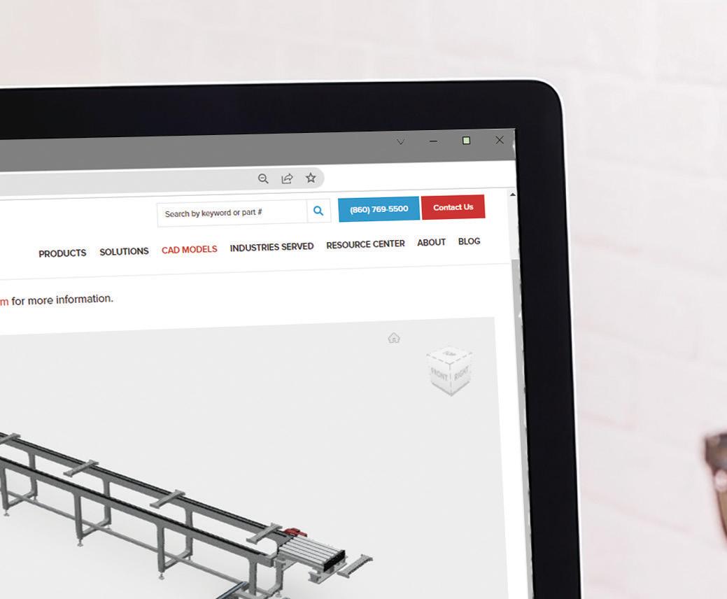
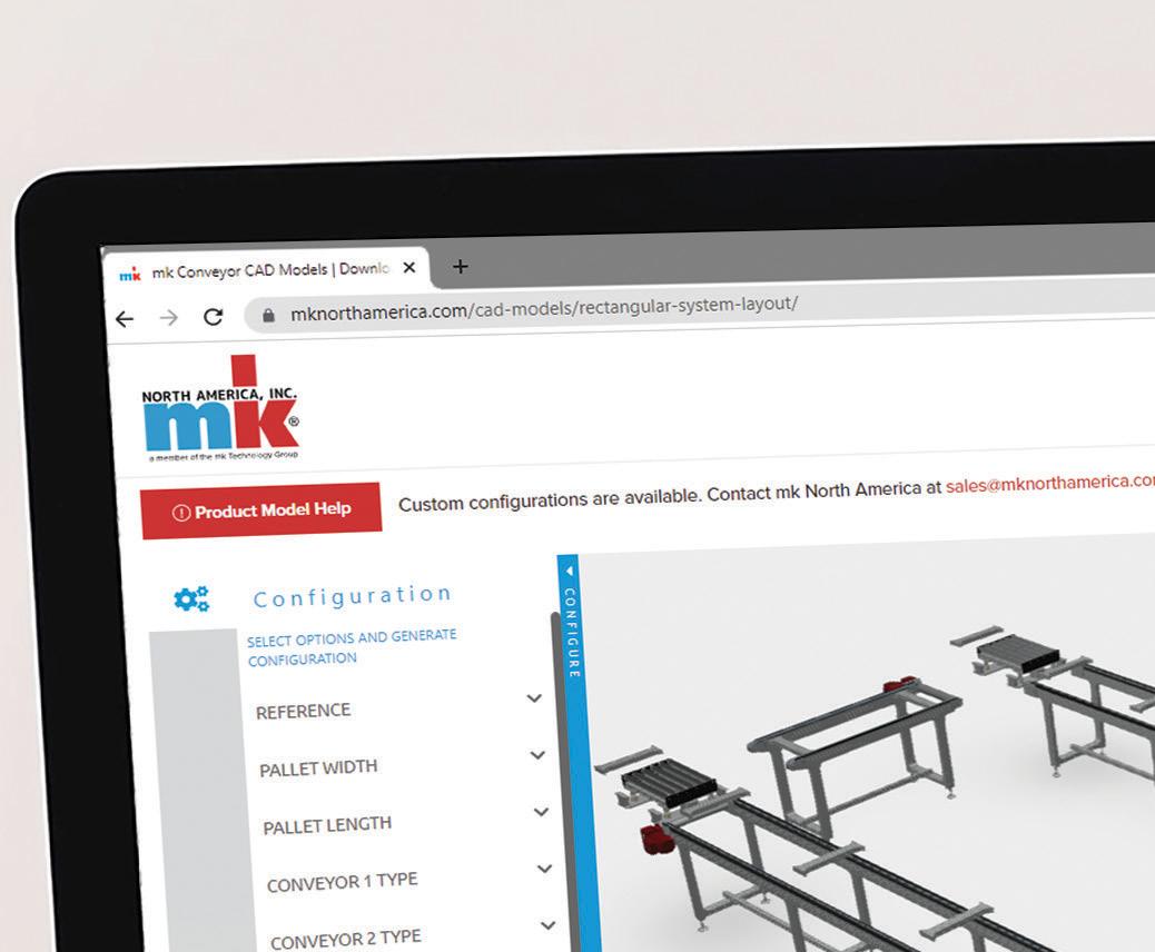
www.mkCAD360.com better products. better solutions. (860) 769-5500 | info@mknorthamerica.com Conveyor Models at Your Fingertips Customize and download conveyor models within minutes with mk’s CAD360. CAD360!
With timing-belt conveyors, servo drives accurately start and stop for precise part location. Encoders on a conveyor’s drive shaft sense shaft rotation or count pulley revolutions for belt control in feeding or indexing.
to swing out of the way when workers need to walk through the line. In other arrangements serving a similar purpose, interlock switches and a timer can let conveyor sections clear before a gate opens. Then in some cases, controls automatically resume product flow after the conveyor returns to the inline position.
Single-drive multi-belt conveyors serve two or more lanes of product for the sake of efficiency. Here, multiple conveyors run off one gearmotor on a common drive shaft or coupled shafts. In some arrangements, the belts mount to a single conveyor frame. Backlit conveyors have light fixtures installed inside the frames to emit light through translucent belts. Such conveyors are used in applications calling for inline vision or visualsystem interface inspection
processes by supplying enhanced contrast between the product and conveyor belt. Parts can be stopped directly over the lighted section or can continue through uninterrupted. The most common applications that backlit conveyors support are those relying on visual part inspections for quality control.
There are other conveyor subsystems and units. Case in point: A knife edge conveyor unit is a uniquely designed subsystem for the transferring of small parts off or on a conveyor or between conveyor sections. The term knife edge refers to the subsystem’s defining element — a tightly tapered and rounded end. Knife-edge conveyor subsystems often incorporate small rollers or a steel plate called a nosebar having one end rounded to a small radius —down to a few millimeters in some cases. Then the product-carrying conveyor belt wraps around this tight geometry to allow easy transfer between conveyor-system sections while ensuring that parts don’t fall in the gap at the conveyor end. Knife-edge conveyor subsystems excel at transporting items such as credit cards and even smaller and more delicate items such as electronics and pharmaceuticals ... as well as limp or floppy items such as cookie dough.
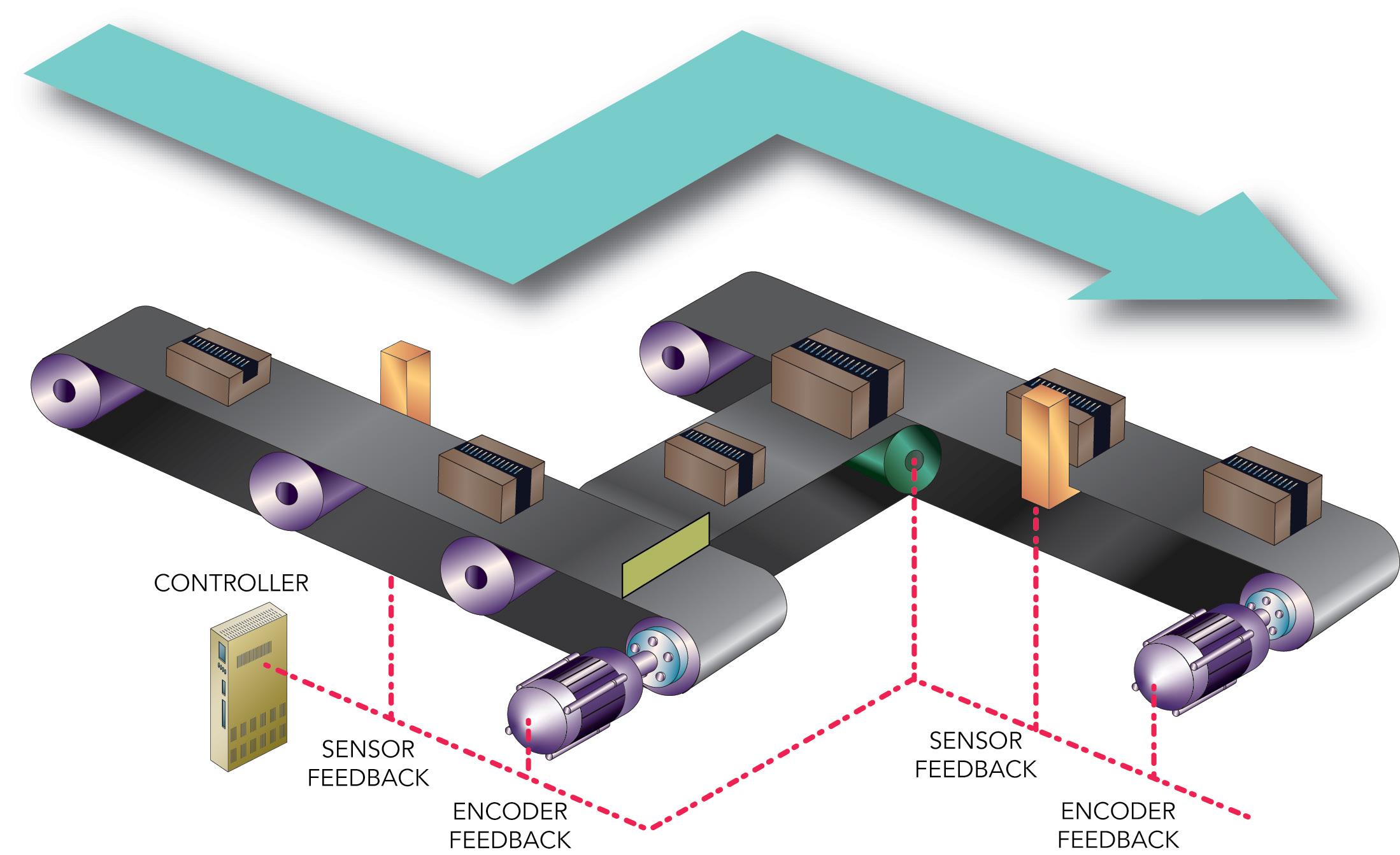
motion control handbook
40 DESIGN WORLD — MOTION 8 • 2023 motioncontroltips.com | designworldonline.com
KNIFE-EDGE RADIUS R
KNIFE-EDGE CONVEYOR END
TRADITIONAL CONVEYOR END
Knife-edge conveyor units have a small radius R to minimize the gap between adjacent conveyors that workpieces or other items must traverse.


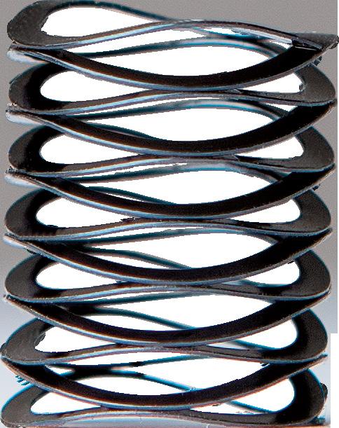
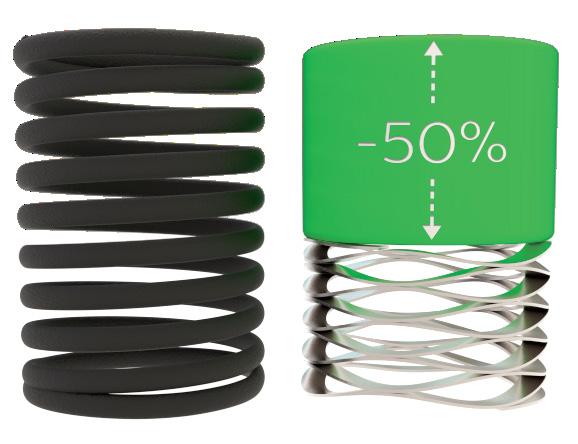
Application Driven Solutions™ Request Samples rotorclip.com Product Focused, Support Driven Reduce Operating Heights By Up To 50% Free Engineering Support: info@rotorclip.com • +1.732.469.7333 Thousands of applications supported Diameters from .100" to 140" Stainless steel & exotic alloys readily available Custom engineered capabilities
RECONSIDERING DISC COUPLINGS
Disc couplings include two hubs of aluminum, stainless steel, or other grades of steel that sandwich a pack of discs. Like a deck of cards, each thin element of this disc pack (sometimes called a disc spring) is the same size.
This stack of discs is pressed together by bushing-fitted bolts that induce torque-transmitting friction between the discs. In some cases, the thin discs are made of stainless steel; in other instances, they’re made of engineered composite material.
Because torque transmits through the faces of the discs, there’s no backlash or issues with stress concentrations that would arise in a coupling having only the bolt shanks to transmit torque. Friction operation also imparts torsional stiffness.
Like jaw couplings, variations of disc couplings abound … with many satisfying applications characterized as heavy industry, power transmission, and process equipment. But other variations of disc couplings are applied in high-performance motion applications that
require the precision transmission of torque and speed as well at the accommodation of shaft misalignment.
Typical maximum torques for all disc couplings are 100 to 678,000 Nm. Refer to couplingtips.com for more on their ability to address combinations of angular and parallel misalignment. Maximum speeds from specialized offerings are to 10,000 rpm.
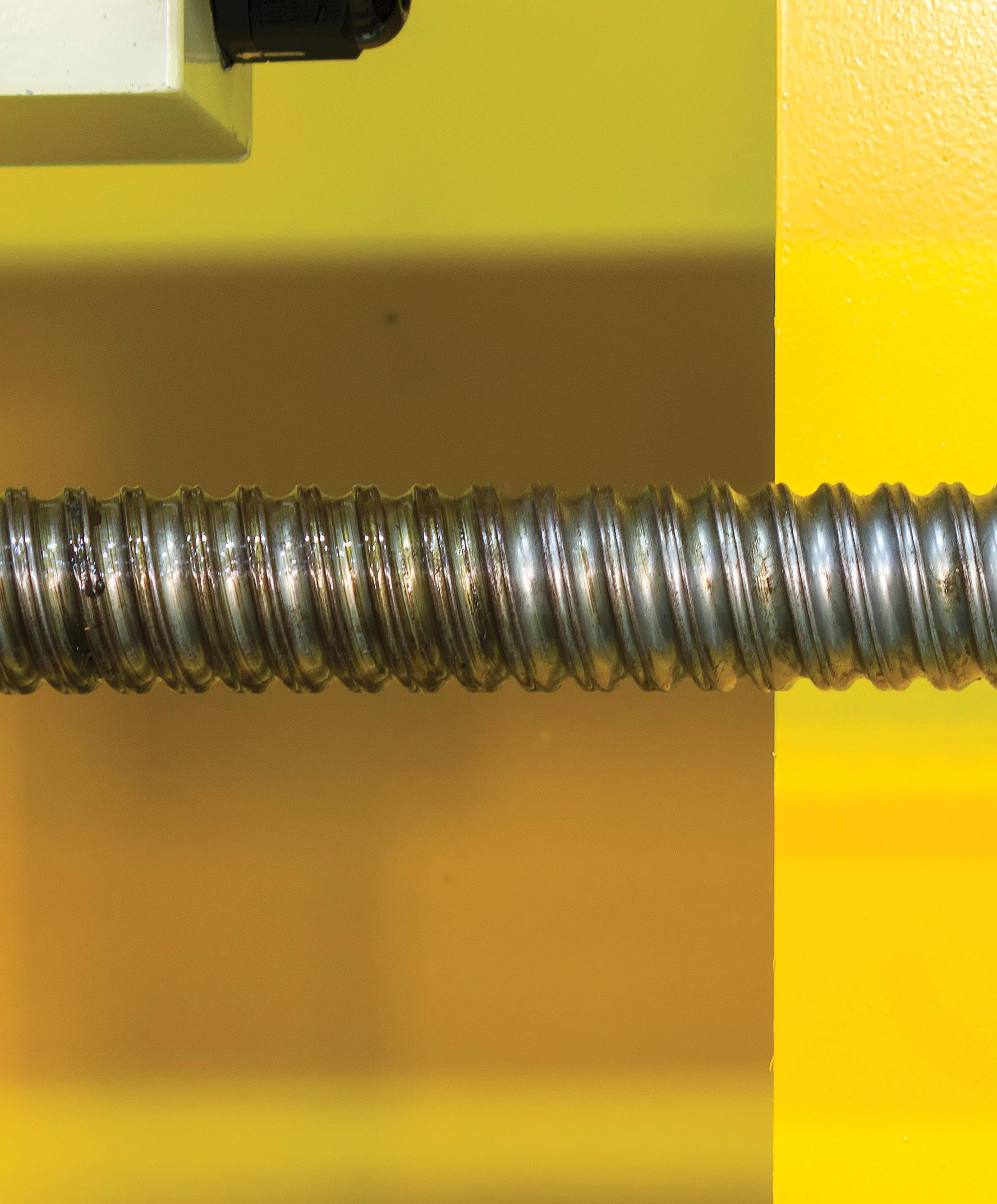
Disc-coupling designs
Single-disc couplings should perhaps be called single disc-pack couplings … because they include a single disc pack having many friction discs. In industry their less ambiguous name is single-flex couplings.
In contrast, double-disc couplings (in industry referred to as double-flex couplings) have two disc packs — with an additional center hub between them. In some cases, this center spacer is of the same material as the two end hubs; otherwise the component supplier may offer center spacers made of something else — acetal for electrical isolation, for example.
Other disc-coupling variations abound. Some include:
42 DESIGN WORLD — MOTION 8 • 2023 motioncontroltips.com | designworldonline.com
motion control handbook
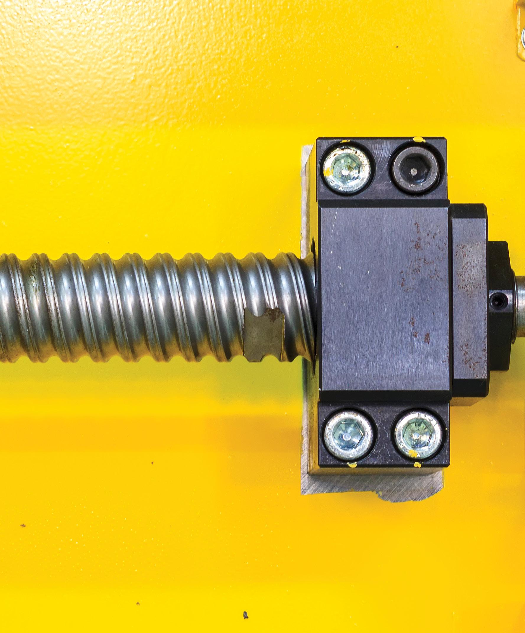
couplings 43 DESIGN WORLD — MOTION 5 • 2023 motioncontroltips.com | designworldonline.com
Image: Shutterstock
LASER-BASED SHAFT ALIGNMENT: MOST COMMON SYSTEM
A projected laser cone contains the shaft’s rotational center.
A projected laser cone is brought to a point on the shaft’s rotational center.
Belt drives are indispensable in appliance applications that need to be reasonably quiet. (Image courtesy of Nikkytok)
TOOL-LESS ADJUSTMENT COMPONENTS
• Adjustable handles and knobs replace standard hardware and can be used to torque components without tools.
• Levers can be used with Ruland shaft collars for quick installation and adjustment.
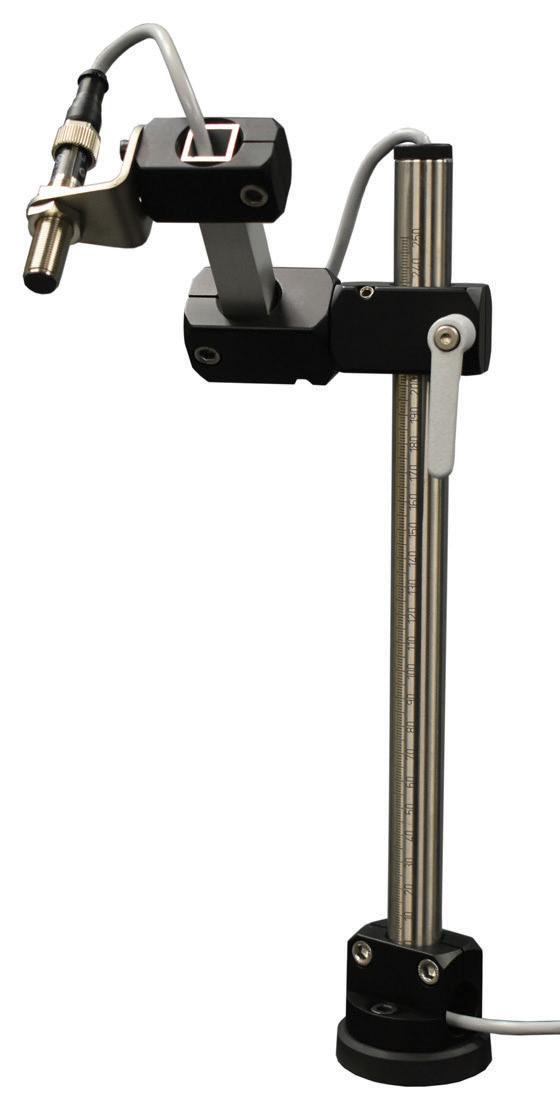
All products available directly on RULAND.COM
PRECISION COUPLINGS
• Beam couplings accommodate light weights and high misalignment.
• Zero-backlash jaw couplings for vibration dampening and a variety of performance options.
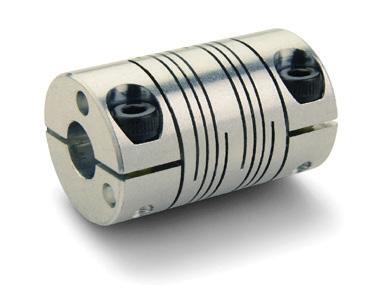
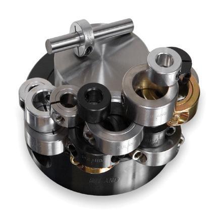
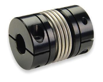
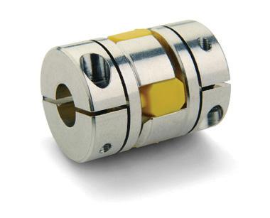
• Bellows couplings for high size to torque ratio.
Ruland Manufacturing is proud to support the FIRST Robotics Competition as a Gold Supplier of precision shaft collars & couplings.
SHAFT COLLARS
• Thousands of size and style options.
• Proprietary manufacturing processes ensure superior fit and finish.
• 8 material options.
VIBRATION ISOLATING COMPONENTS
• Rubber bumpers are ideal as end stops or mounting feet.
• Vibration isolation mounts can be sandwiched between components to dampen shock loads.
• Both types can have studs or tapped holes.
MODULAR MOUNTING SYSTEMS
• Assorted components allow you to build small assemblies for mounting sensors, conveyor rails, machine guards, and more.
• Optional pre-designed kits make it easier to select the right system for your application.
QUICK CLAMPING COLLARS
• No tools required to install, remove, and adjust.
• Best suited for systems that require frequent adjustments.

ruland.com | sales@ruland.com
WHAT’S NEW RULAND from
• Laminated discs
• Discs of circular or hexagonal or other shape
• Attachments through the disc pack
• Attachments alternating between the two hub flanges
• Features to satisfy API, ATEX, and other standards


Although typical single-flex couplings incorporating steel discs accommodate no parallel misalignment, this limitation isn’t universal: Those with composite discs can accommodate a modest amount of parallel misalignment. That’s useful in compact machine footprints that don’t allow the extra length of a double-flex coupling. But where longer axes are acceptable and more dramatic parallel misalignment is unavoidable, double-flex couplings leverage the ability of two discs to flex in opposing directions for accommodating offsets.
Disc couplings ≠ diaphragm couplings
Diaphragm couplings — a completely different design than disc couplings — are nevertheless confused with and mistakenly substituted the latter. Note that diaphragm couplings transmit torque via one or more thin diaphragms. The diaphragm or diaphragm pack attaches to one shaft hub near its inner diameter and to the other near its outer diameter. Deflection on this attachment differential’s freespan accommodates both axial and angular misalignment.
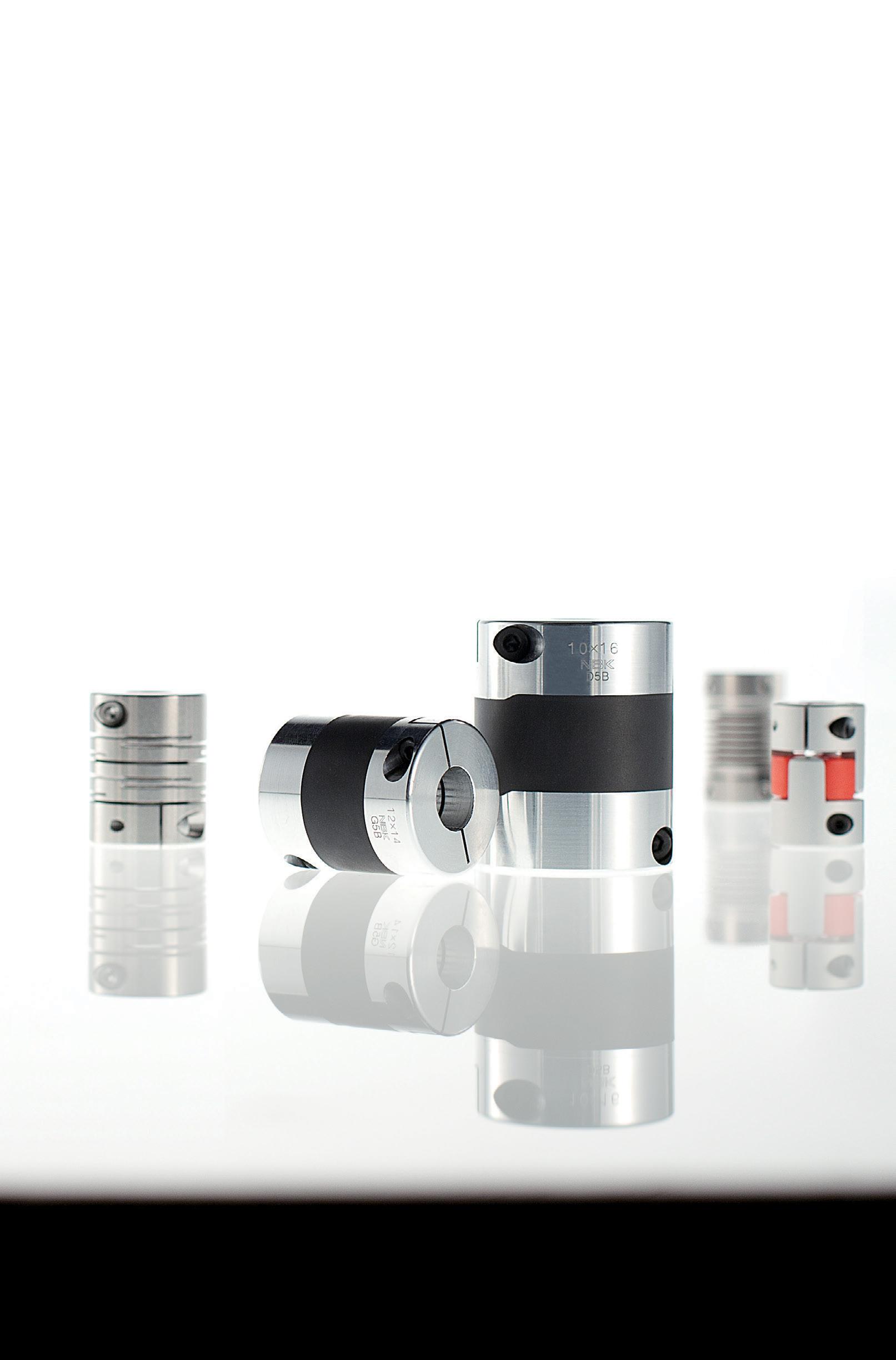
couplings 45 DESIGN WORLD — MOTION
DEFINING SERVO-GRADE GEARING AND MOTORS
Servomotors are broadly categorized as those with feedback and closed-loop control. These motors deliver precise torque, speed, and position control and even run at zero speed while maintaining enough torque to hold loads.
Unlike most other electric-motor-driven options, servomotors can move axes through complex strokes and motion profiles. Their high precision minimizes position error as well.
46 DESIGN WORLD — MOTION 8 • 2023 motioncontroltips.com | designworldonline.com
motion control handbook
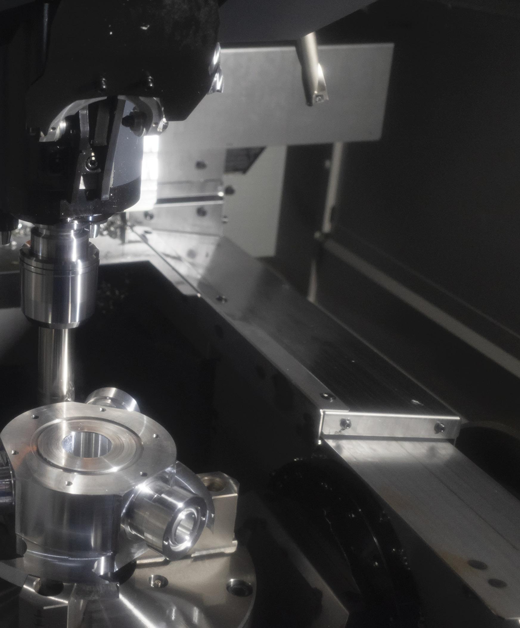
servogears & gearmotors 47 DESIGN WORLD — MOTION 8 • 2023 motioncontroltips.com | designworldonline.com
Servomotor tuning is key to quality CNC-based machining of molds. Image: Dreamstime • Sorapol Ujjin
Advanced Products for Robotics and Automation

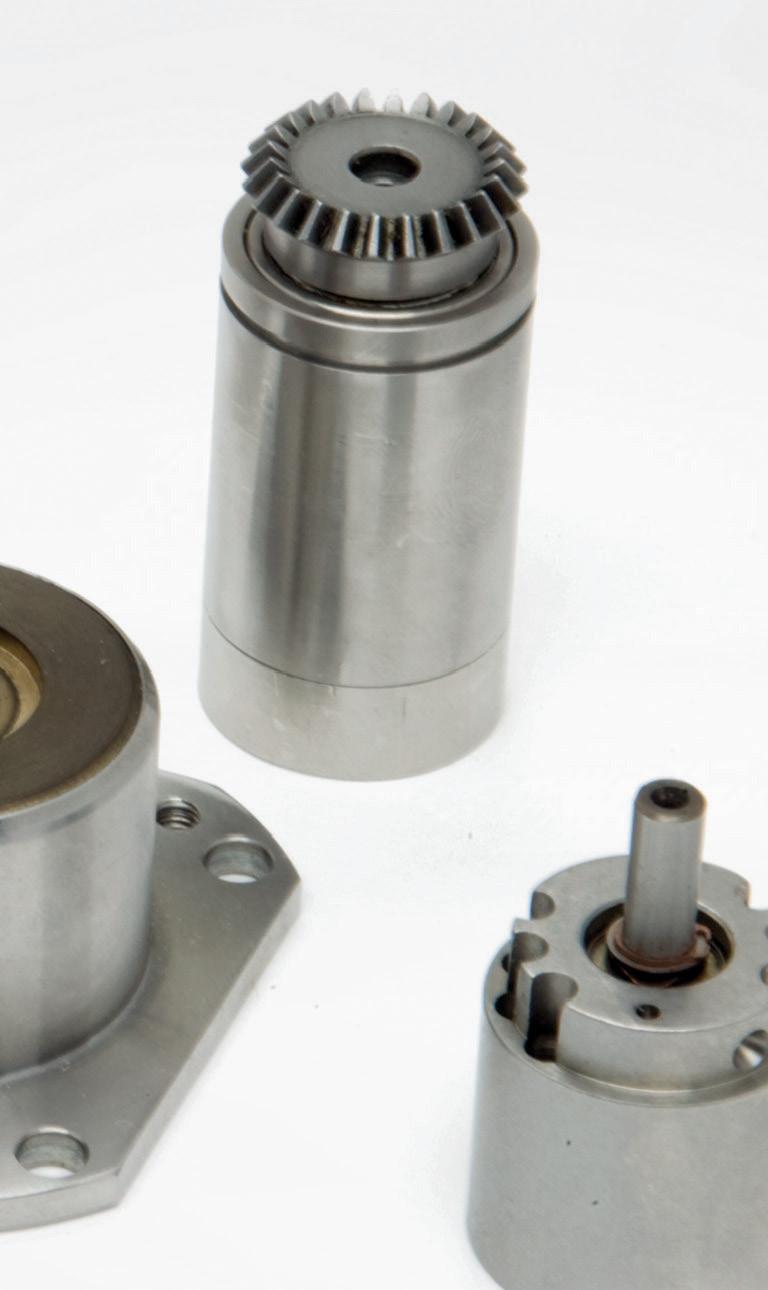
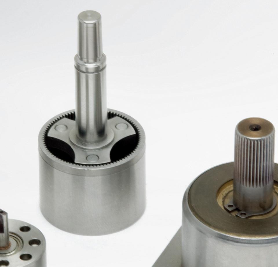
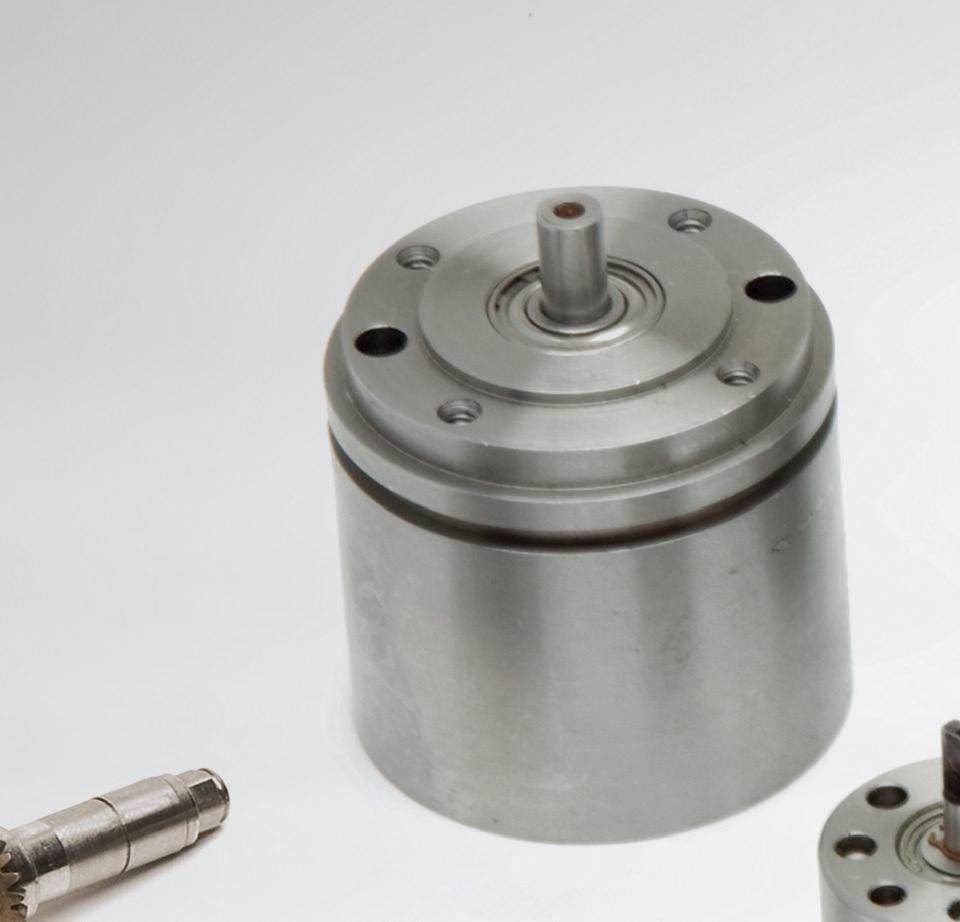


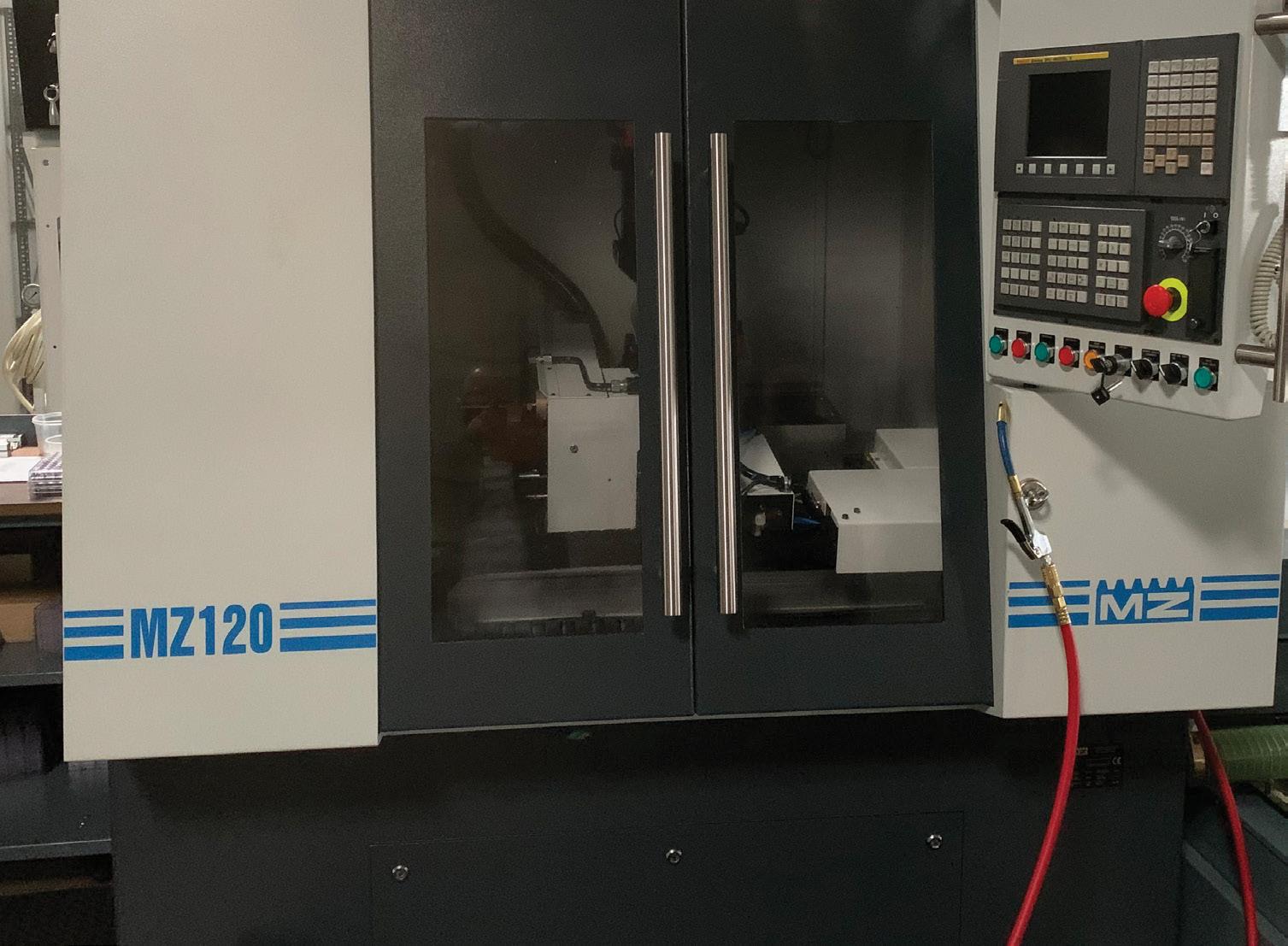
CGI Motion standard products are designed with customization in mind. Our team of experts will work with you on selecting the optimal base product and craft a unique solution to help di erentiate your product or application. So when you think customization, think standard CGI assemblies.

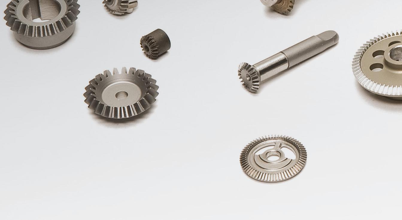
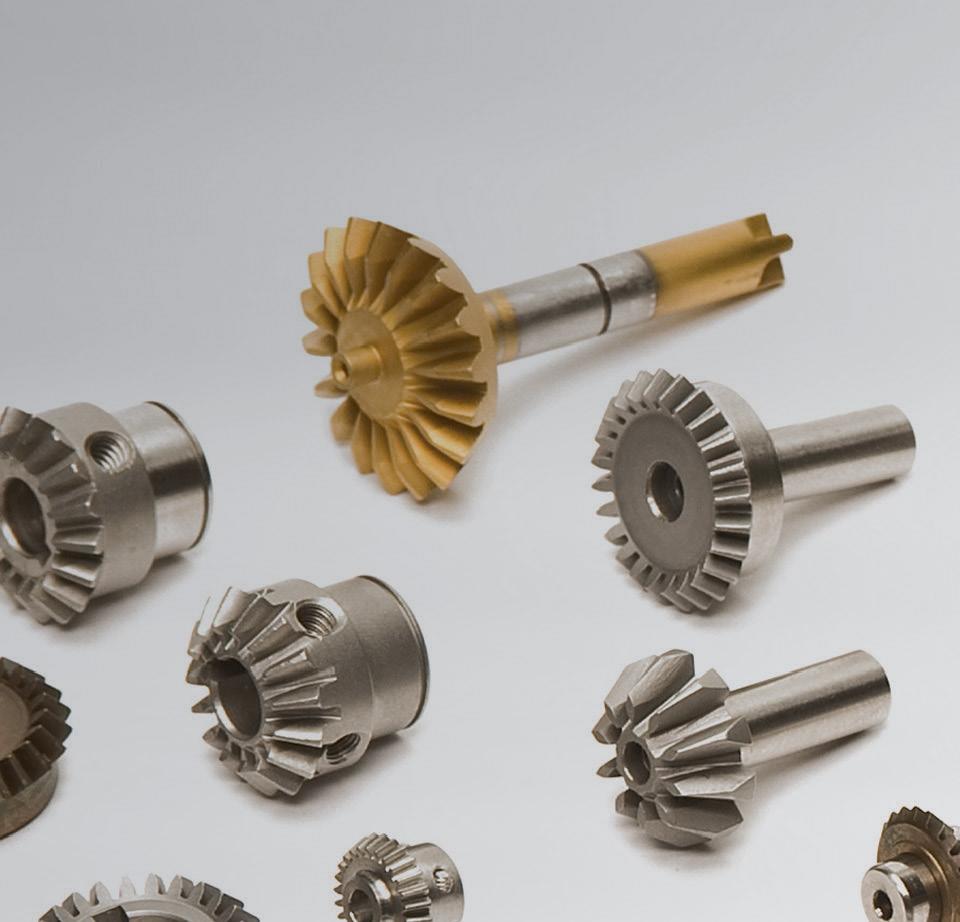
Connect with us today to explore what CGI Motion can do for you.


copyright©2021 cgi inc. all rights reserved. YOUR CUSTOM SOLUTIONS
ARE CGI STANDARD PRODUCTS
800.568.GEAR (4327) • www.cgimotion.com
Manufacturers classify motors for constantspeed tasks by horsepower — or torque at base speed. In contrast, servomotors operate over speed ranges ... so aren’t rated this way. Instead, they have speed-torque curves that express continuous torque capabilities (that won’t threaten to overheat the motor) and intermittent or peak torque for acceleration.
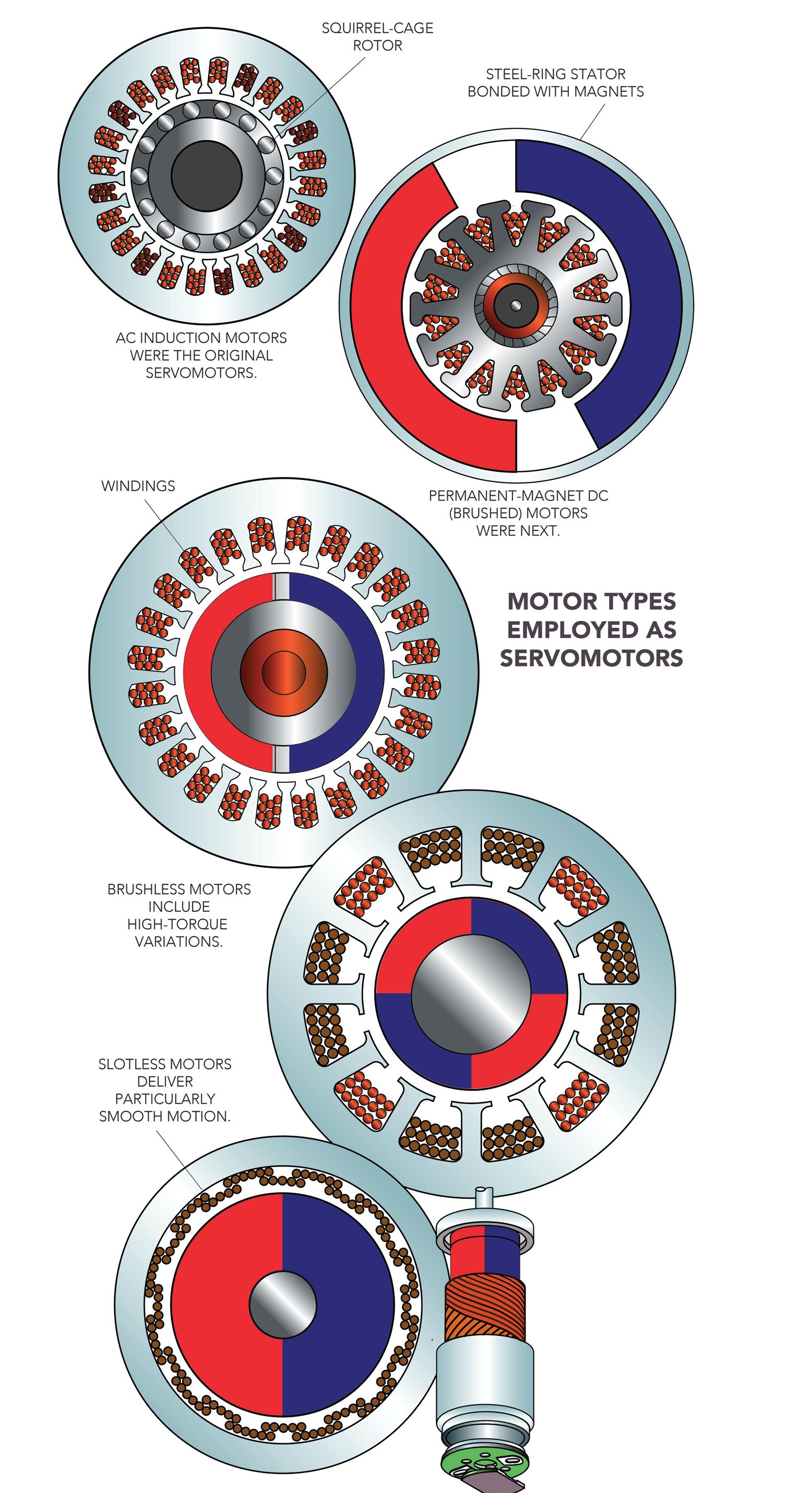
As we’ll explore in more depth, servomotor selection begins with the defining (using application inertia) how much load the axis will move. Then the engineer determines application speed or velocity — and how far and fast the load needs to travel.
Calculating torque is next — and then plotting anticipated torques on the prospective motors’ torque-speed curves — as the servomotors’ continuous and peak torque limits over the axis’ full speed range.
So is picking and sizing an appropriate servomotor complex? Often yes — but there are many manufacturer software programs out there to help make it easier. The other good news is that once a designer has the parameters for an axis and its motor, he or she can setup its drive to protect the rest of the system’s components by preventing excessive torques and other problematic conditions.
Many servomotors that aren’t direct drive have top speeds up to thousands of rpm — so to better leverage their full capabilities, designers will often combine such motors with gearing to trade an increase in output torque with lower output speed. Much of the time, this gearing takes the form of planetary or harmonic gearheads — precision arrangements with high accuracy and efficiency.
In many cases, gearing even lets machine builders use smaller motors on servo axes — which equates to cost savings that may even
The first servomotors were two and three-phase induction motors. Then came brushed motors (permanent-magnet dc motors) to leverage advances in electronics and magnet formulations. Linear and predictable performance from brushed servomotors make them easy to apply. However, many new servo designs today employ brushless permanent-magnet motors for quick response thanks to relatively low inertia.
servogears & gearmotors
49 DESIGN WORLD — MOTION 8 • 2023 motioncontroltips.com | designworldonline.com
Precise. Powerful. Modular.
Servo motors and gear units from SEW-EURODRIVE
Servo motors and gear units from SEWEURODRIVE offer a high degree of dynamics and performance with a compact design, making them excellent for confined spaces. Multiple frame sizes and torque ratings makes them the perfect fit in material handling, hoist and gantry applications, and a wide variety of
machine automation applications. Their modular design allows for direct gear unit mounting without adapters or couplings. Pair that with the option of single-cable technology and you’ve got a flexible, precise servo drive solution.
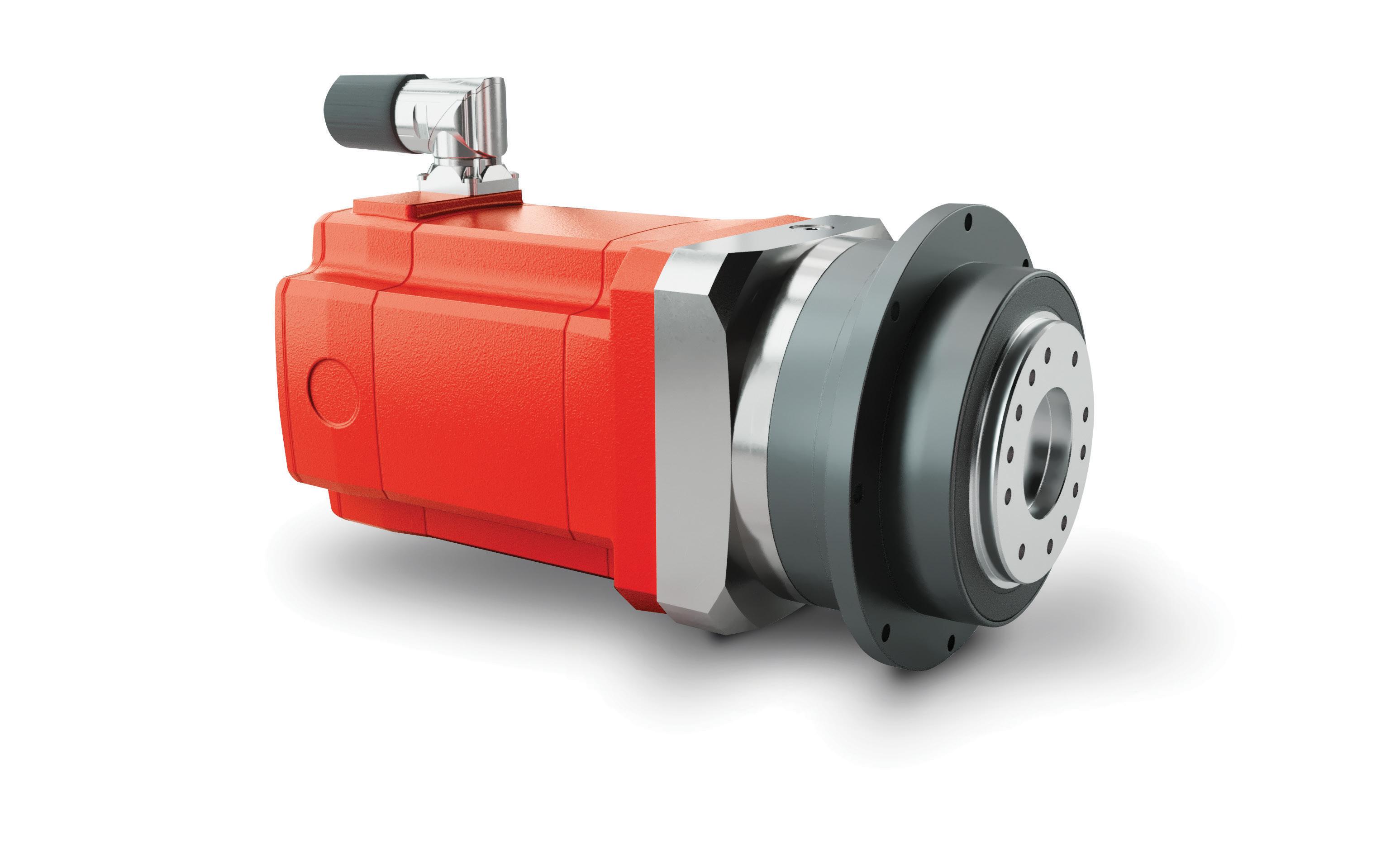
www.seweurodrive.com
offset the price of additional gearing. Keep in mind that the term servomotor can mean different things depending on the context. Convention is that the term often (though definitely not always) refers to what industry calls dc motors — brushed and the costlier (but longer-lived) brushless servomotors.
Technically, dc brushless motors run off ac power — shaped into a square wave current that’s fed to the motor’s phases in a predefined sequence – so-called electronic commutation. What the industry calls an ac brushless motor is the same permanent-magnet synchronous design — just optimized to accept sinusoidal ac current into its phases instead. Some argue that industry should forever rename dc brushless motors to trapezoidally wound motors — and (to be consistent) we should call ac brushless motors sinusoidally wound motors.
Just remember that brushed servomotors give linear and predictable performance that makes them easy to apply. Brushless motors usually run applications needing more torque; the only catch here is that their drives are more complex because commutation is done electronically and not mechanically as in brushed types.
Industry also categorizes motors in part by their number of electrical phases. Brush dc servomotors as well as voice coil motors are in fact single-phase motors, whereas brushless servomotors most commonly have three phases.
Some sources classify induction-motorbased designs running off vector controls as servomotor setups where the design incorporates feedback (usually from an encoder) to track and control speed and sometimes even position. These induction motors typically adhere to NEMA or metric standards, whereas other servomotor offerings are less uniform, as their design roots are in application-specific setups.
Motor types used as servomotors
As mentioned, servomotor systems incorporate an electric motor, controller, and feedback device. The electric motor is either ac or dc. Servo setups that run off vector controls include induction motors paired with feedback (usually from an encoder) to track and control speed all the way down to full stops. Programmable versions can also control position. Here a common application is positioning — a quintessential servo task that puts vectorcontrolled motors in a class with brushless and
brushed servomotors.
Note that the industry also categorizes servomotors into the categories of single-phase or three-phase. Single-phase variety types are anything from simple brushed dc motors to voice coils for small micropositioning and nanopositioning.
Still another servomotor variation is the integrated servomotor — usually including a controller, feedback device, drive (amplifier), and networking hardware and software. Fewer separate parts means more reliability, and fewer external connections means less cabling and associated cost.
Designers can quickly program these integrated servomotors for shorter development times. Communications include simple serial communication links such as RS232 or RS485 and advanced network topologies including CANopen, DeviceNet, and other protocols based on Ethernet.
More on motor construction types

Servomotors are used in applications where precise control of position, speed, or torque is required. But many different types of motors can be considered servomotors — the defining feature of a servomotor is that it incorporates or reads feedback in a closed-loop system. In fact, although many servo applications use synchronous ac motors, dc motors can also be used in servo systems.
Synchronous ac motors are typically brushless (the exception being universal motors, which are mechanically commutated with brushes and can run on either ac or dc power supply). Likewise, the DC motors used in servo systems are most commonly brushless types ... typically called BLDC motors.
Brushed dc motors can operate in a servo system, but the wear and maintenance they require — due to the mechanical brushes and commutator — make them less desirable for most servo applications. This article explains when it can be advantageous to use a brushed dc motor in a servo system, and specifically, what type of brushed dc motors are best for servo applications.
Recall that brushless dc motors use permanent magnets on the rotor and coils in the stator to produce rotation (and torque). This configuration is like a synchronous ac motor, but a key difference between BLDC motors and synchronous ac motors is in how the stator coils are wound. In a synchronous ac motor, the coils are wound sinusoidally and commutation
servogears & gearmotors 51 DESIGN WORLD — MOTION 8 • 2023
is a continuous, sinusoidal waveform. This gives synchronous ac motors very smooth performance. BLDC motors, on the other hand, have trapezoidally wound stator coils and commutation that takes place in six steps — every 60° — which can lead to torque ripple.
BLDC motor construction variations: Brushless dc motors are typically constructed with a stator made from slotted steel laminations and copper windings inserted into the slots. Slotted designs can be constructed with the rotor at the center of the motor and the stator surrounding the rotor — sometimes called an inrunner or internal rotor, design. This reduces the motor’s inertia and allows for very dynamic performance.
Alternatively, slotted BLDC motors can be constructed with the slotted stator at the center of the motor and the rotor magnets surrounding the stator … sometimes called an outrunner or external rotor, design. This allows the motor to produce high torque and to be constructed with a short overall length — called a “flat” design — but at the expense of reduced dynamics due to higher rotor inertia.
Whether constructed with an internal or external rotor, slotted BLDC motors suffer from cogging torque due to the permanent
magnets in the rotor attempting to line up with the slots of the stator. The primary effect of cogging torque is that it causes motor rotation to be jerky, especially at low motor speeds.
A newer permutation of the BLDC motor is the slotless design. This design does away with the slotted steel laminations and instead uses a stator constructed of steel rings stacked together, with the windings encapsulated in an epoxy resin. The winding is placed in the air gap between the stator lamination and the rotor (which resides in the center of the motor).
The slotless design eliminates cogging torque, reduces audible noise, and reduces inductance, so acceleration and dynamic response are improved over slotted designs. BLDC motors are often used in servo applications that require high efficiency, high reliability, and good torque density (torque production for a given size), but without the magnitude of torque production that can be provided by large synchronous ac motors.
Common applications for BLDC servomotors include robot joints, medical devices, and packaging equipment. Brushless dc motors are also suitable for batterypowered equipment and for applications that
Image: Dreamstime • Tonbady
require direct integration of the motor into the mechanical design thanks to their numerous design options and the myriad ways they can be customized.

Typical gearing in motion systems
Because servo systems are precision-motion setups with feedback and (in most cases) fairly stringent accuracy demands, engineers should pick servogear reducers with good torsional stiffness, reliable output torque, and minimal backlash. OEMs tasked with integrating servo systems should look for quiet reducers that easily mount to the motor and require little or (if possible) no maintenance. In fact, advanced machinery often integrates servogears into application-specific electromechanical arrangements … and several of these arrangements are common enough to have specific labels. Here is a look at some of the most widespread.
Gearmotor: This complete motion component is a gear reducer integrated with an ac or dc electric motor. Usually the motor includes the gears on its output (typically in the form of an assembled gearbox) to reduce speed and boost available output torque. Engineers use gearmotors in machines that must move
Six-axis robotic applications make copious use of brushless servomotors. Brushless servos offer higher speed and torque from smaller packages than comparable motors; they run applications that need higher torque … and are reliable and virtually maintenance free.
motion control handbook 52 DESIGN WORLD — MOTION 8 • 2023 motioncontroltips.com | designworldonline.com
Simplify.
Rotary Actuators with Integrated Servo Drive
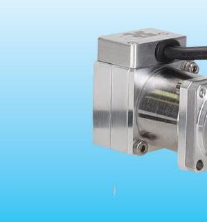


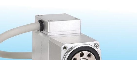
The Servo Drive is Inside!
The IDT Series is a family of compact actuators with an integrated servo drive with CANopen® communication. They deliver high torque with exceptional accuracy and repeatability, and feature Harmonic Drive® precision strain wave gears combined with a brushless servomotor. Some models are available with a brake and two magnetic absolute encoders with the second providing output position sensing. This revolutionary product line eliminates the need for an external drive and greatly simplifies cabling, yet delivers high-positional accuracy and torsional stiffness with a compact form factor.
• Actuator with Integrated Servo Drive utilizing CANopen®

• 24 or 48 VDC nominal supply voltage
• A single cable with only 4 conductors is needed: CANH, CANL, +VDC, 0VDC


• Zero Backlash Harmonic Drive® Gearing

• Panel Mount Connectors or Pigtail Cables
Available with Radial and Axial Options


• Control Modes include: Torque, Velocity, and Position Control, CSP, CSV, CST


Harmonic Drive is a registered trademark of Harmonic Drive LLC. CANopen is a registered trademark of CAN in Automation. 42 Dunham Ridge, Beverly, MA 01915 | 800.921.3332 | www.HarmonicDrive.net
heavy objects. Speed specifications for gearmotors are normal speed and stallspeed torque.
Gearbox: This is a fully integrated mechanical component consisting of a series of mating gears contained in a housing with shafts and bearings (to support and resolve loads) and in many cases a flange for motor mounting.
Gearhead: Most of the motion industry makes no differentiation between the terms gearhead and gearbox. But in a few contexts, the term gearbox specifically refers to housed gearing as described above while the more general term gearhead also refers to assemblies of otherwise open gearing that installs within some existing machine frame. The latter are often targeted to compact, consumergrade, or battery-powered mobile designs necessitating especially tight integration and omission of potentially redundant subcomponents. In one variation, a series of parallel plates might support gear-train
shafts (and bearings) and allow bolting to a motor face.
Other open gearing simply mounts to the electric-motor output and operates exposed to the environment. Some such open gearing is self-lubricating — constructed of dimensionally stable polyamides or similar materials engineered to meet stringent cleanliness, vibration, weight, and cost requirements.
More on planetary gearsets
Particularly common in servo systems, planetary gearsets consist of one or more outer planet gears that revolve about a central sun gear. Typically the planet gears mount on a movable arm or carrier that rotates relative to the sun gear. The sets often use an outer ring gear, or annulus, that meshes with the planet gears. The gear ratio of a planetary set requires calculation, because there are several ways they can convert an input rotation to an output rotation.
Typically, one of these three gear wheels stays stationary; another is an input
Brushless servomotors require encoders or Hall sensors to track the rotor for controls to properly energize the windings for optimized motion output and (as mentioned elsewhere) need relatively sophisticated drives for electronic commutation (and not the simpler mechanical commutation for brushed dc motors).
that provides power to the system, and the last acts as an output that receives power from the driving motor. The ratio of input rotation to output rotation depends on the number of teeth in each gear and on which component is held stationary.
Planetary gearsets offer several advantages over other gearsets. These include high power density, the ability to get large reductions from a small volume, multiple kinematic combinations, pure torsional reactions, and coaxial shafting.
Another advantage to planetary gearbox arrangements is powertransmission efficiency. Losses are typically less than 3% per stage, so rather than waste energy on mechanical losses inside the gearbox, these gearboxes transmit a high proportion of the energy for productive motion output.
Planetary gearbox arrangements distribute load efficiently, too.
Multiple planets share transmitted load, which greatly increases torque density. The more planets in the system, the greater load ability and the higher the
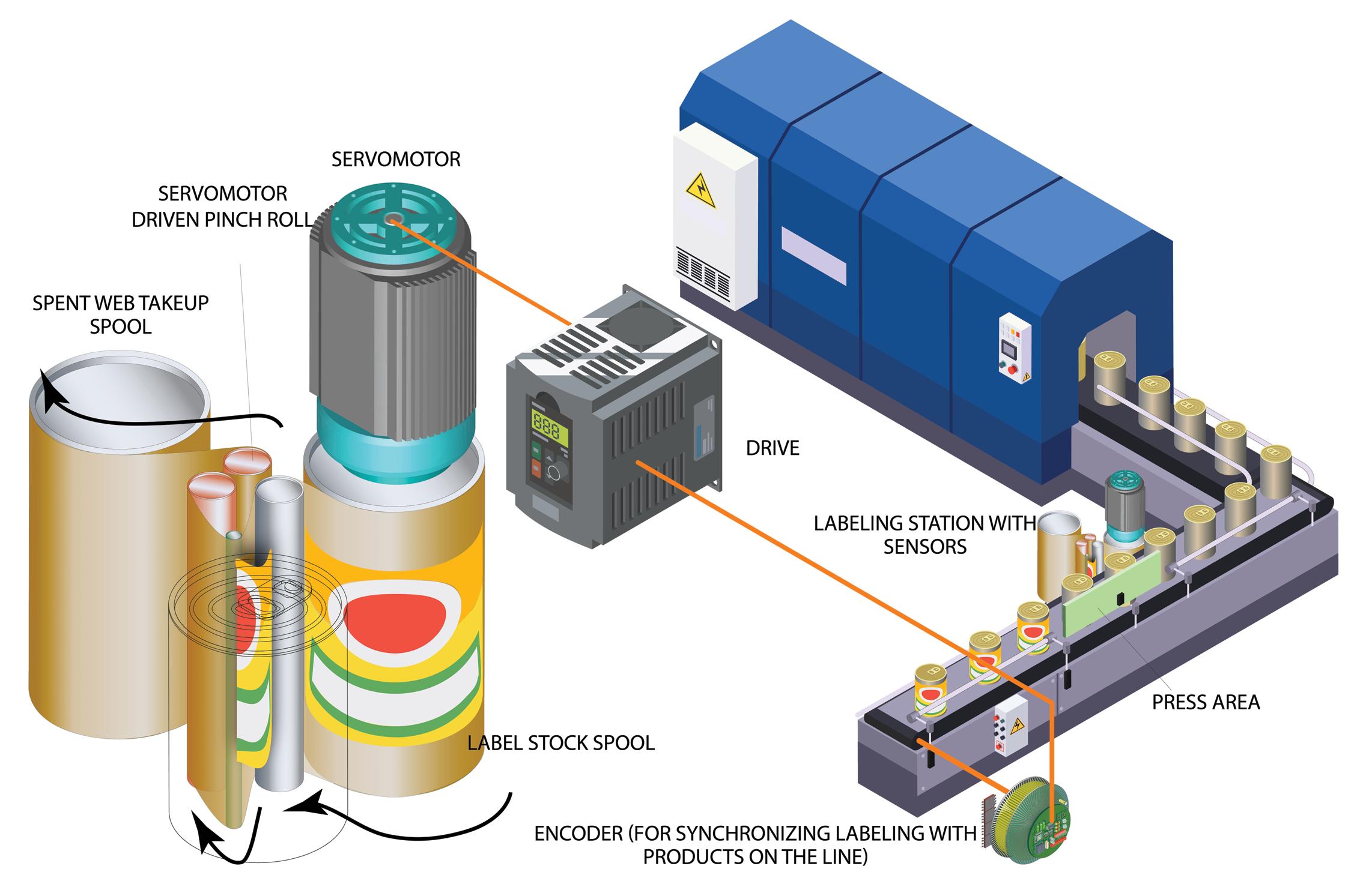
motion control handbook 54 DESIGN WORLD — MOTION 8 • 2023 motioncontroltips.com | designworldonline.com

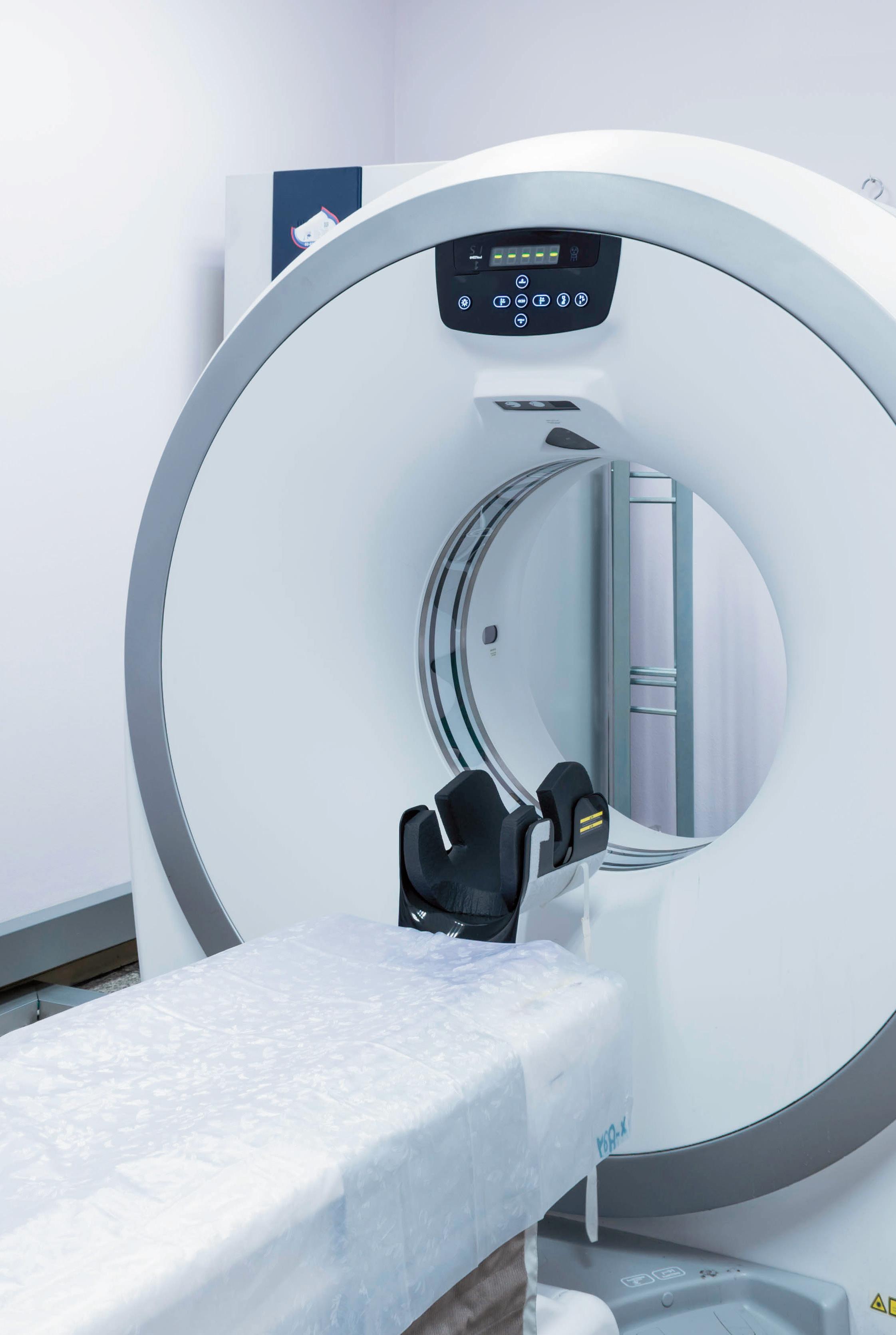


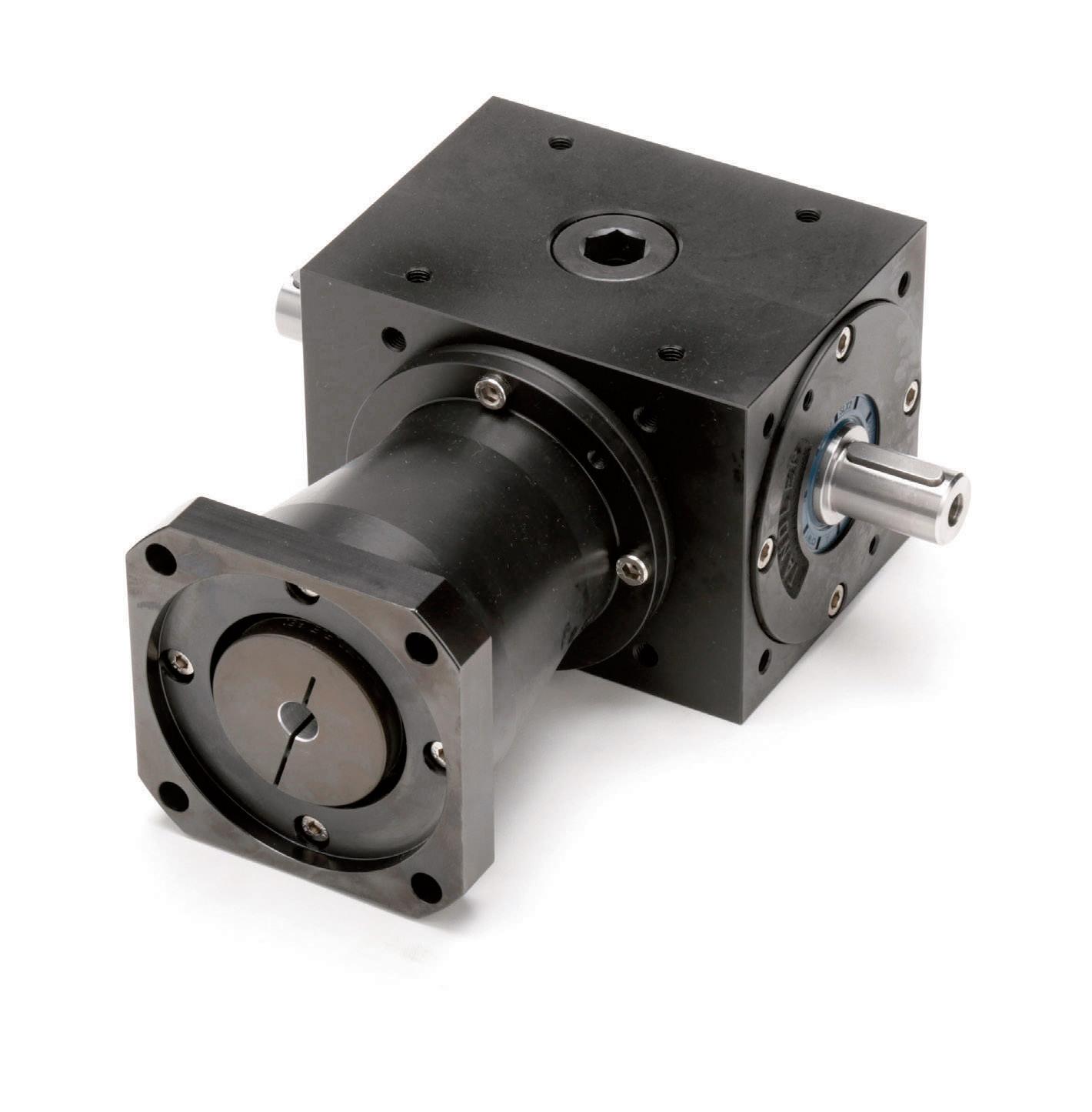
Motion Components to Automate any Industry 800-363-2145 diequa.com/dw Right Angle Precision Servo Gearheads with Single or DUAL Output Options
torque density. This arrangement is also very stable due to the even distribution of mass and increased rotational stiffness. Disadvantages include high bearing loads, inaccessibility, and design complexity.
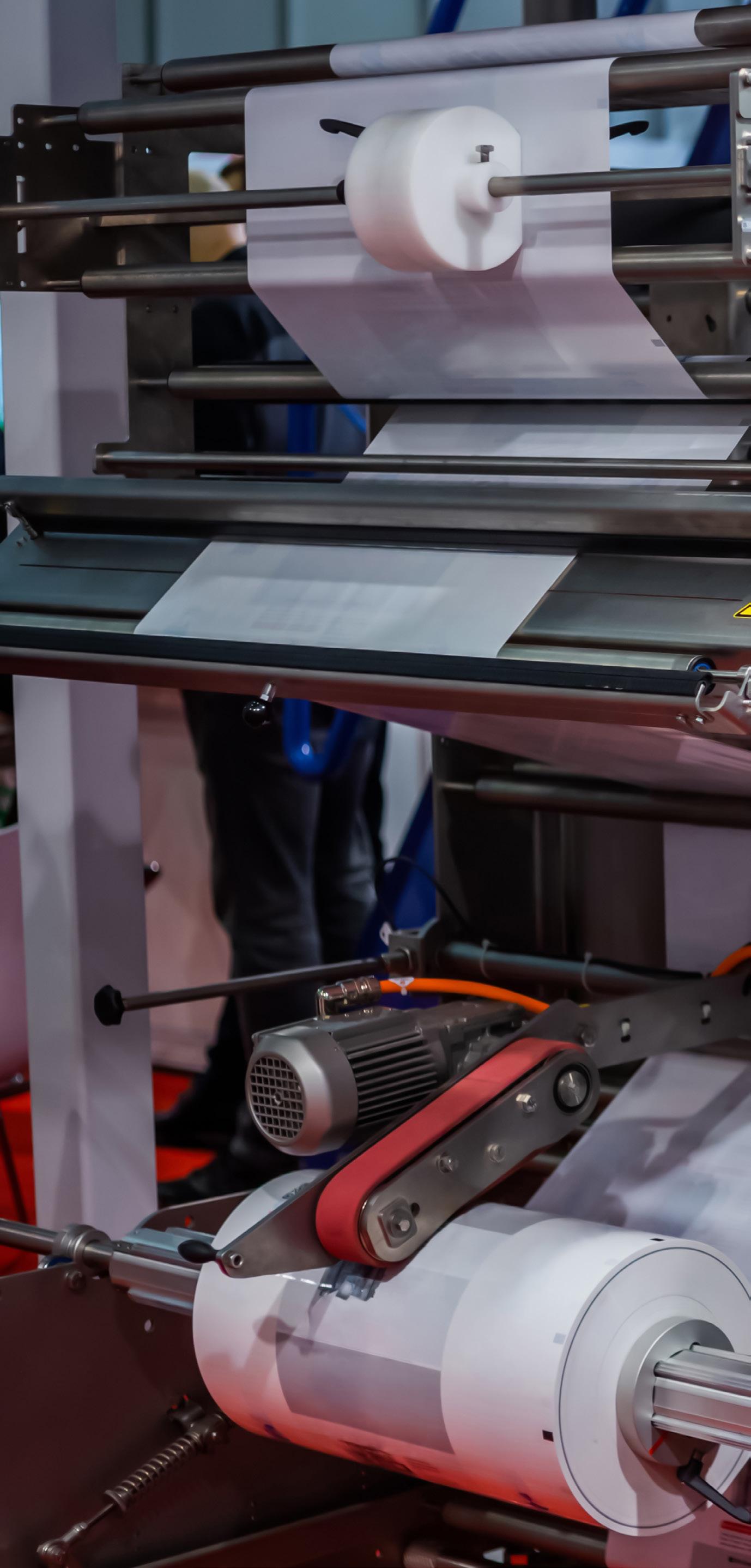
In servo systems, besides boosting output torque, gearboxes impart another benefit — reducing settling time. Settling time is a problem when motor inertia is low compared to load inertia … an issue that’s the source of constant debate (and regular improvement) in the industry. Gearboxes reduce the reflected inertia at the controls by a factor equal to the gear reduction squared.
More on hypoid gearing options
Hypoid gearboxes are a type of spiral bevel gearbox — with the difference that hypoid gears have axes that are non-intersecting and not parallel. In other words, the axes of hypoid gears are offset from one another. The basic geometry of the hypoid gear is hyperbolic rather than having the conical geometry of a spiral bevel gear.
In a hypoid gearbox, the spiral angle of the pinion is larger than the spiral angle of the gear, so the pinion diameter can be larger than that of a bevel gear pinion. This provides more contact area and better tooth strength, which allows more torque to be transmitted and high gear ratios (up to 200:1) to be used. Because the shafts of hypoid gears don’t intersect, bearings can be used on both sides of the gear to provide extra rigidity.
The difference in spiral angles between the pinion and the crown (larger gear) causes some sliding along the teeth, but the sliding is uniform, both in the direction of the tooth profile and longitudinal.
This gives hypoid gearboxes very smooth-running properties and quiet operation. But it also requires special extreme pressure (EP) gear oil to maintain effective lubrication due to the pressure between the teeth.
Hypoid gearboxes are generally used where speeds exceed 1,000 rpm ... although above 8,000 rpm ground gears are recommended.
However, hypoid gearing is also useful for lower speed applications that
motion control handbook 56 DESIGN WORLD — MOTION 8 • 2023 motioncontroltips.com | designworldonline.com
Form, fill, and seal servomotor design: Dreamstime
require extreme smoothness of motion or quiet operation. In multi-stage gearboxes, hypoid gears are often used for the output stage, where lower speeds and high torques are required.
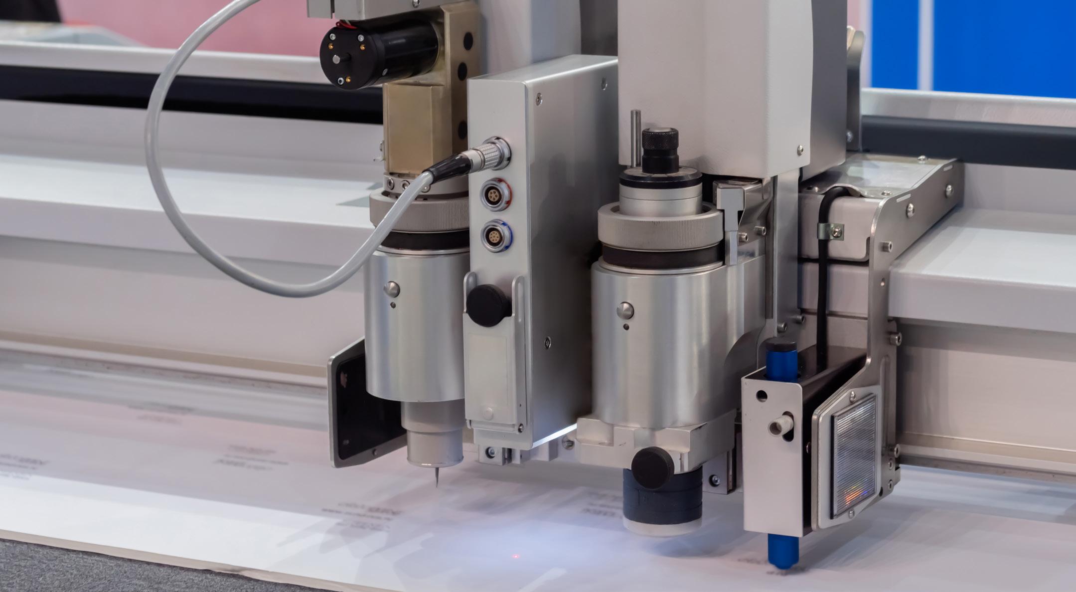
The most common application for hypoid gearboxes is in the automotive industry, where they are used in rear axles — especially for large trucks.
With a left-hand spiral angle on the pinion and a right-hand spiral angle on the crown, these applications have what is known as a below-center offset ... which allows the driveshaft to be located lower in the vehicle. This lowers the vehicle’s center of gravity and in some cases reduces interference with the interior vehicle space.
Considering servomotor inertia
Inertia is an object’s resistance to a change in speed. To determine the inertia of an object, its mass is multiplied by the square of its distance from the axis of rotation.
A familiar demonstration of inertia is a figure skater on the ice. When she spins with her arms close to her body, her mass is close to her axis of rotation and her rate
of spin is fast. But when she extends her arms, the distance of her mass from the axis of rotation is increased, making her inertia larger and causing her to spin at a slower rate.
In an electromechanical system, both the motor and load have inertia, and how similar (or different) their inertias are will affect system performance. The ratio of the load inertia to the motor inertia is one of the most important aspects of servomotor sizing:
Where J L = inertia of load reflected to motor; J D = inertia of actuator or drive (ball screw, belt, rack & pinion); J E = inertia of external (moved) load; and JC = inertia of coupling.
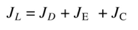
For the motor to effectively and efficiently control the load during acceleration and deceleration, the motor and load inertias should theoretically be equal. However, a 1:1 inertia match is rarely practical or achievable.
Where J L = inertia of load reflected to motor and J M = inertia of motor. Motor inertia is given by the manufacturer, while the load inertia is calculated by adding the inertia of all rotating parts. These inertias typically include those of the actuator or drive (whether belt, ballscrew, or rack and pinion) and the external load as well as the coupling:
Many factors influence what inertia ratio is acceptable for a given application, but one of the most import is the compliance or windup in the system. Mechanical components are not perfectly rigid, and the more components in the drive train — belts, couplings, and gearboxes — the more compliance the system will have. In general, the higher the compliance, the lower the inertia ratio should be to let the motor effectively control the load.
While there’s no formula for determining the best inertia ratio, some motor sizing guidelines stipulate that the inertia ratio should be 10:1 or lower.
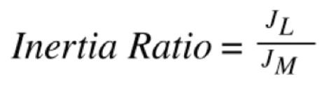
motion control handbook 58 DESIGN WORLD — MOTION 8 • 2023 motioncontroltips.com | designworldonline.com
Cutting servomotor design: Dreamstime


FAULHABER Applications With Drive Systems from FAULHABER, you will take automation and robotics solutions for logistics to a new level. More at: www.faulhaber.com/logistics-robot/en WE CREATE MOTION Learn more CO2 N E UTRAL through co mpensation
Game changer in logistics
Higher mismatches cause the motor to draw more current than necessary, which decreases efficiency and increases operating costs. A higher ratio also increases resonance and can cause the system to overshoot the desired velocity and position, negatively affecting performance.
If the inertia ratio is too high, there are two ways to reduce it: Add a gearbox to the system or use a larger motor.
Gearboxes are frequently used in belt driven systems to optimize motor speed and torque. But gearboxes can significantly reduce the inertia ratio of the system because the gear ratio has an inverse square effect on the inertia of the load:
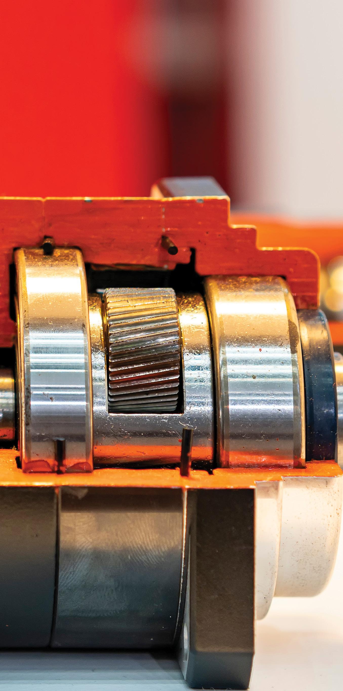
Where JG = inertia of gearbox and i = gear ratio. The second method for reducing the inertia ratio is to use a larger motor with higher inertia. However, this is rarely a beneficial solution in the long term, because a larger motor costs more; requires more torque to overcome its own inertia; and consumes more energy than smaller solutions — which all increase the system’s total cost of ownership.
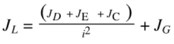
On the other hand, an inertia ratio that is unnecessarily low or even a 1:1 match can indicate that the motor is oversized, which results in unnecessary cost and energy consumption.
Rather than striving for an arbitrary inertia ratio, designers should take into account the system dynamics and positioning requirements and strive for an inertia match that achieves these requirements with a servomotor that is neither over or undersized
motion control handbook 60 DESIGN WORLD — MOTION 8 • 2023 motioncontroltips.com | designworldonline.com
Image: Adobe stock

ENCODER SPOTLIGHT: RADIAL AND RING ENCODERS
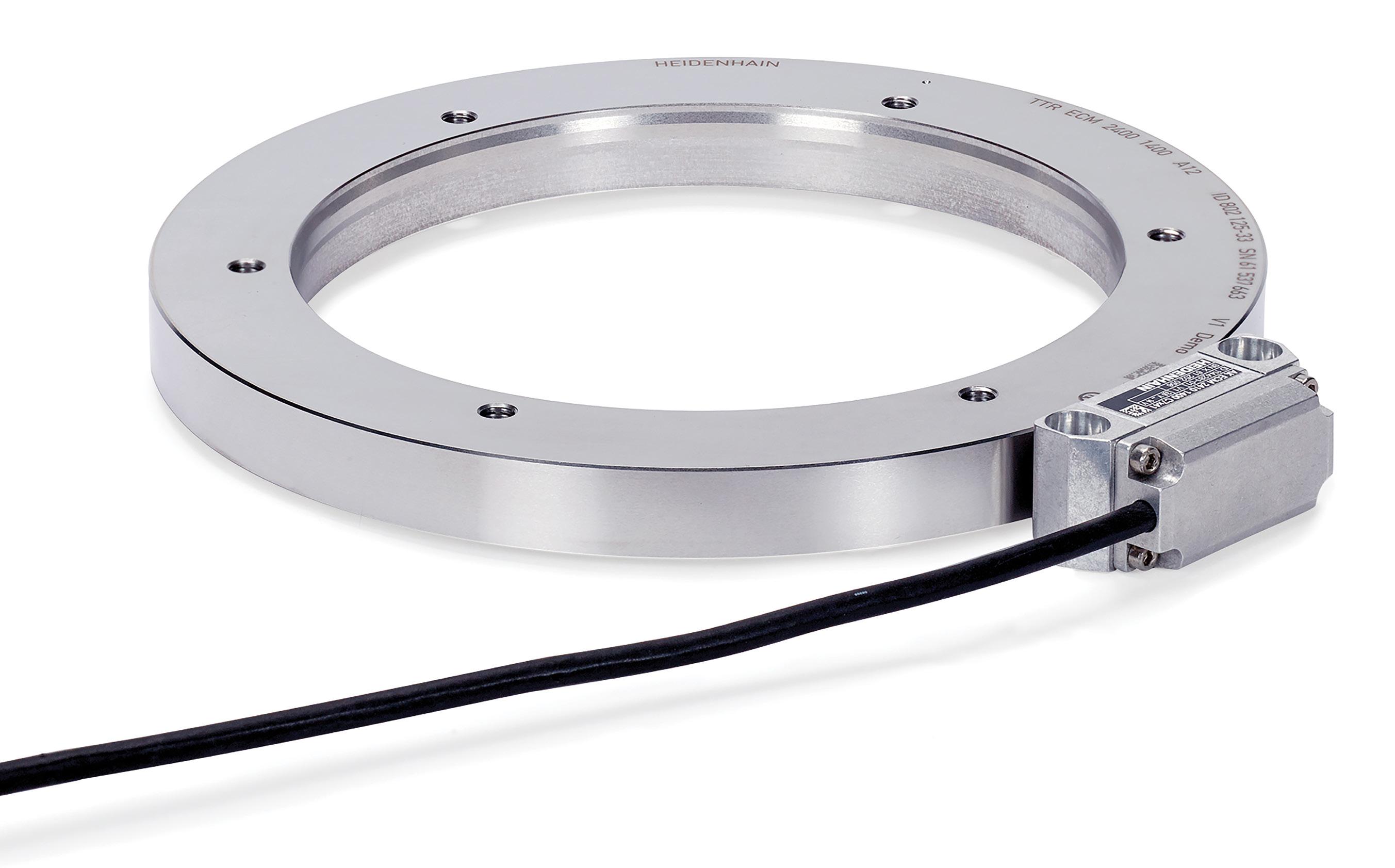
Encoders measure position, distance traveled, and speed, providing a vital source of feedback in motion control systems. They’re classified by operating principle, absolute or incremental, rotary or linear.
Consider operating principle — optical, magnetic, or capacitive. Optical encoders were some of the earliest with fairly high resolution, using a light source for detection. Magnetic technology doesn’t use any optical means and can achieve resolutions down to a micron, competing with optical technology in a host of applications. Magnetic technology is also more robust than optical technology, making magnetic encoders more common in harsh industrial environments. Lastly, there are capacitive encoders. They offer resolution comparable to optical devices with the ruggedness of magnetic encoders, making them suitable for applications.
motion control handbook
62 DESIGN WORLD — MOTION 8 • 2023 motioncontroltips.com | designworldonline.com
Ring encoders such as this ECM 2400 absolute magnetic ring encoder from HEIDENHAIN work well in applications requiring a large hollow shaft encoder such as machine tool applications.
The difference between absolute and incremental encoders is another fundamental point of classification. Absolute encoders have an encoder disc (sporting marks or slots) on a powertransmission shaft and a stationary pickup, but the disc marks output a unique code for each shaft position. Absolute encoders are either single-turn or multi turn encoders. Single turn absolute encoders can verify position within a single turn of the encoder shaft. This makes them useful for short travel situations. In contrast, multiple-turn absolute encoders are better for more complex or longer positioning situations.
In contrast, rotary incremental encoders work by generating a series of pulses during movement. The encoder disc (sporting marks or slots) attaches to a power-transmission shaft, and a stationary pickup device mounts nearby. When the shaft and disc turn, the pickup tracks the motion to output the relative position. Such encoders generally supply square-wave signals in two channels that are offset (out of phase) by 90° ... and each increment of rotation spurs an output signal.
Differences between radial and axial ring encoders
A traditional rotary encoder measures the position or speed of a rotating shaft, with mounting via a coupling or a hollow bore that allows the encoder to fit over the shaft. But not all rotating components have a shaft to which the encoder can mount. For example, direct-drive rotary motors — also
Measuring-wheel encoders
known as torque motors, pancake motors, or Lorentz force motors, depending on their construction and operation — are designed without input or output shafts. Since traditional shaft encoders aren’t suitable, these applications typically use ring encoders — a type of rotary encoder characterized by a large hollow bore and a small axial height.
Ring encoders — also known as through-bore encoders or large bore hollow shaft encoders — consist of two components: a ring, which contains the measuring scale, and a scanning unit, which contains the sensing element and electronics.
The encoder components are mounted separately and integrated directly into the application — for example, directly into a robot joint, or directly on the face of a NEMA C-Face motor. Unlike other rotary encoder designs, ring encoders don’t require support bearings, and they’re completely contact-free, so they can operate at higher rotational speeds and tolerate high shock and vibration loads.
Depending on the required scanning head orientation, the encoder ring can be a radial or an axial type. Radial ring encoders have an encoder scale located on the outer “edge” of the ring, so that the scanning unit is located on the side of the ring and faces inward, radially toward the center of the ring’s bore.
Alternatively, axial ring encoders have a scale located on the “face” of the ring, so that the scanning unit faces along the axis of the encoder.
Linear encoder technologies can also take the form of rotary encoders combined with precision-engineered measuring wheels having precision bearings and sporting polyurethane, rubber, or knurled aluminum treads. The most suitable tread choice depends on the application’s competing requirements for traction and long life. The most suitable wheel diameter depends on the axis speed and resolution requirements. With these encoders, typically a spring-loaded wheel mount joins with an encoder shaft while allowing the wheel itself to ride a surface associated with the machine axis in question. OEMs can source such measuring wheels and assume the task of mounting them to their machines’ encoder shafts — or specify fully integrated measuring-wheel encoder components. The latter offer compactness, factoryguaranteed alignment with mounting brackets, and essentially unlimited measuring distance — a key advantage over encoders relying on linear scales. They also mount in nearly any orientation.
Another advantage of measuring-wheel encoders is ruggedness: They leverage the durability of rotary encoders (that often exceeds comparable components relying on linear scales) and various bearing arrangements for high load capacity.
INTRODUCING THE WORLD’S SMALLEST MULTI-TURN KIT ENCODERS
Miniature Package for Servomotors, Stepper Motors and Microdrives
22 mm diameter, 23 mm depth.
Full multi-turn functionality with maintenance-free rotation counterno backup batteries needed!
17-bit resolution, 32-bit rotation measurement range.
Self-calibration simplifies assembly.
SSI and BiSS C interfacesno license fees.
Find what you need with POSITAL’s online Product Finder.

encoders
www.posital.com 63 DESIGN WORLD — MOTION 8 • 2023
Imagine the benefits of motor feedback and position measurement from a single compact rotary encoder installable on all robot axes.
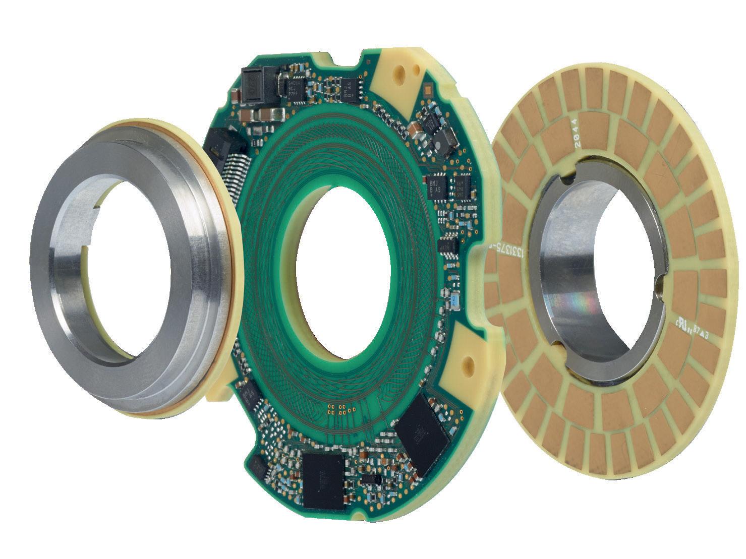
Look no further than the new KCI 120 Dplus dual encoder from HEIDENHAIN. It lets you master the inaccuracies that
plague dynamic, highly articulated robots, such as gearbox backlash and forces induced by the application at the end effector. The KCI 120 Dplus turns a conventional articulated robot into a high-accuracy production system and a dependable cobot.
www.heidenhain.us/industries/robotics

The KCI 120 Dplus dual encoder High-accuracy robot motion Advanced robotics solutions
HEIDENHAIN CORPORATION www.heidenhain.us
Like other rotary encoders, both radial and axial ring encoders can be designed to provide incremental or absolute positioning information and are available with magnetic, optical, and even inductive scanning technologies to meet a wide range of accuracy and resolution requirements and withstand various environmental conditions. Although ring encoders that use magnetic or inductive scanning have relatively large mounting tolerances, optical ring encoders require more precise mounting and alignment.
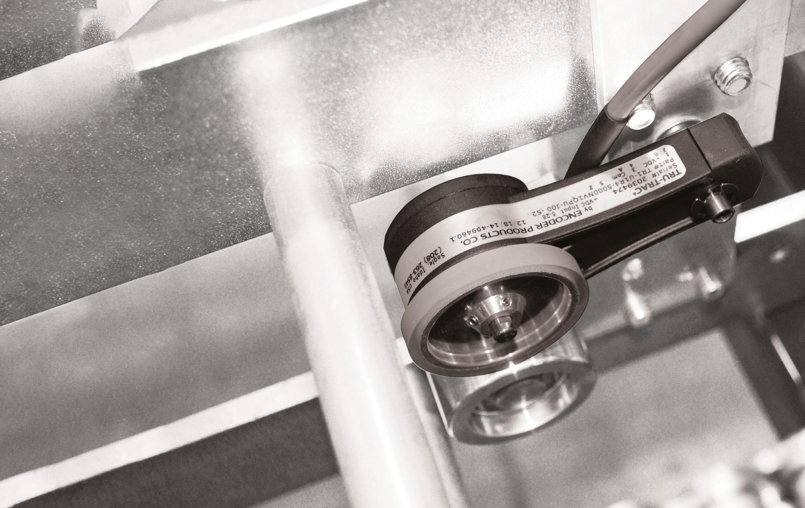
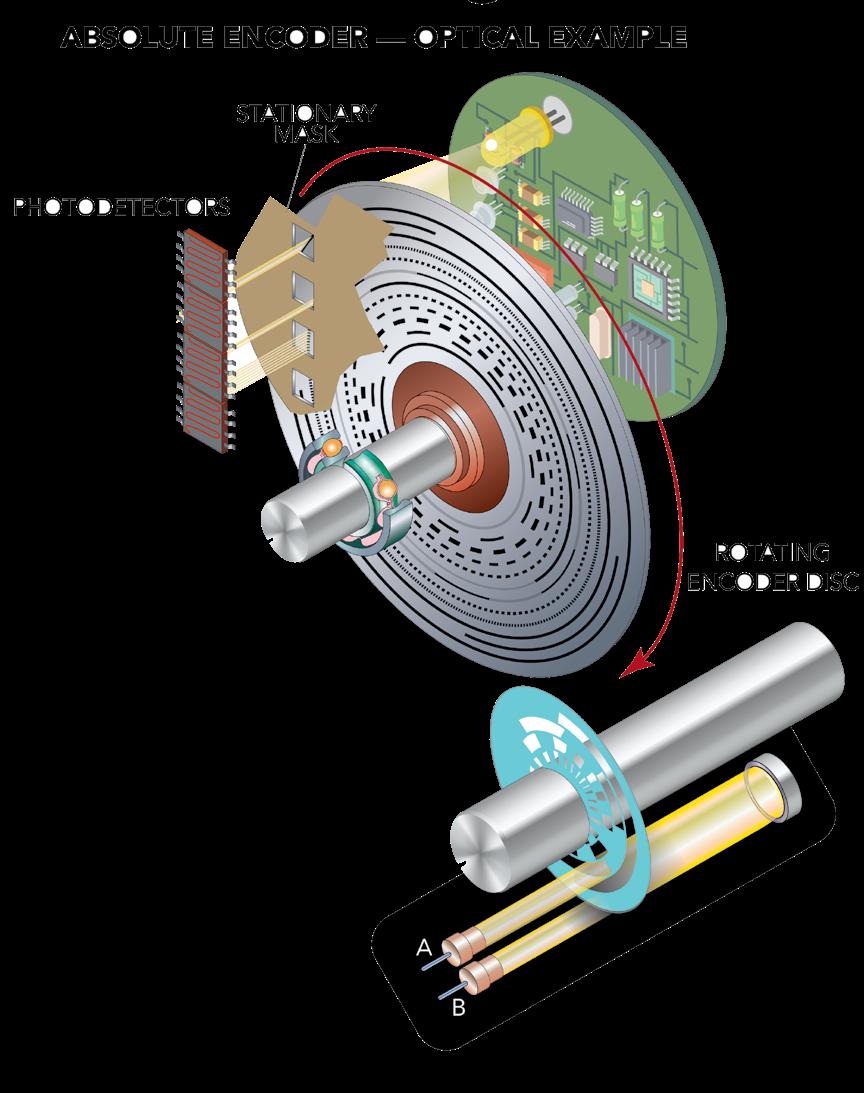
Radial and axial ring encoders are often used in space-constrained applications — especially those that use rotary direct-drive motors such as robot joints and rotary indexing tables and actuators. The ring encoder’s small axial height minimizes footprint, while the large bore provides a pathway for routing cables and pneumatic lines.
Absolute encoders include a sensing mode involving a disc or tape with distinctive marks capable of yielding a unique signal for each shaft or axis position.
The electronics within an absolute encoder interpret detector tracking of the coded element to generate unique position information.
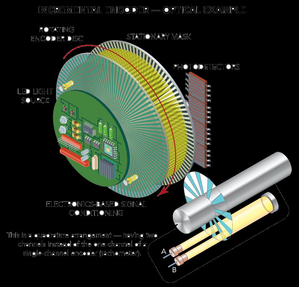
encoders Responsive Experts IN MOTION CONTROL YOUR EPC encoders provide motion feedback for packaging, printing, and marking, and are manufactured in Idaho, USA. Contact us to learn more. 1-800-366-5412 · encoder.com
What can you actually do with ?
The better question is: What can’t you do with it?
Elevate your automation game with XPlanar. Developed in-house by Beckhoff, this mechatronic system makes your production literally fly with magnetically levitating movers and base tiles that you can arrange to fit your unique applications – assembly and packaging, pharma and food, entertainment and beyond.
So, what will you do with XPlanar?
Processing with up to 6 degrees of freedom

Transport and processing in one system
Wear-free, hygienic and easy to clean
Multi-mover control enables parallel and individual product handling

Fully integrated into the powerful and standardized PC-based Beckhoff control system
(TwinCAT, PLC IEC 61131, Motion, Measurement, Machine Learning, Vision, Communication, HMI)

Scan to experience XPlanar in action AT11-19US
Lifting by up to 5 mm Levitating planar movers Velocities up to 2 m/s Tilting by up to 5° 5° 360° rotation 360° Scalable payload kg
IIoT unification with HMIs lets engineers integrate smart-factory equipment into superimposed SCADA, MES, ERP, and cloud services … and blur boundaries between these systems for information technology and operational technology (IT/OT) convergence. That helps operations simplify system configurations, operational adjustments, and managerial actions — as well as optimize maintenance schedules. IIoT HMI technologies also support freer information exchanges between suppliers and end users.
CONNECTED MACHINES AND MOTION CONTROL
The COVID-19 pandemic permanently changed the way in which tens of thousands of businesses worldwide operate. It also changed how many view automation and DX initiatives.
The latter have proven helpful where businesses aim to make remote work for office personnel permanent; toggle operations from on to idled and back more nimbly; allow factory-floor social distancing in more convenient ways; and continually adapt to lingering supply-chain issues. Digital-transformation programs deftly facilitate these and other shifts in business practices.
Core to these capabilities are smart machines that accept commands originating from remote locations; simplify (with software and even AI-driven environmental mapping) reconfiguration as needed; and self-diagnose mechanical and programming issues. In fact, these characteristics are what differentiate smart machines from the merely automated. That’s applicable whether the equipment is a traditional machine that is stationary, a reconfigurable module, or industrial robot. Programming collaborative industrial robots (cobots) to satisfy such smart-machine tasks is especially simple.
Smart-machine communications simplify extraction of data and subsequent analytics, which is in sharp contrast with legacy SCADA systems that demand significant plant-manager attention.
The hardware at which core smart-machine capabilities are primarily localized for discrete automation include industrial controllers, HMIs, and motor drives. Intelligent versions of these components include onboard diagnostics and feedback-handling capabilities to support connected systems’ own data requirements. Case in point: Some inverters incorporate sensors to detect corrosive or dusty conditions in the operation setting; cooling-fan feedback wiring to track fan health; and connectivity ports with circuitry and firmware to facilitate a vast array of IIoT and AI communications.

system design
67 DESIGN WORLD — MOTION 8 • 2023 motioncontroltips.com | designworldonline.com
Maintaining the security of connected machines
One legitimate concern that design engineers have about smart machines is their cybersecurity. After all, connectivity can serve as an avenue for hacking, virus plants, sabotage, and data breaches. Fortunately, standards and solutions abound to build security into smartmachine components. In the U.S., the National Institute of Standards and Technology (NIST) Information Technology Laboratory Applied Cybersecurity Division as well as the Department of Homeland Security’s National Cybersecurity and Communications Integration Center and Industrial Control Systems Cyber Emergency Response Team (ICS-CERT) provide frameworks for reducing the risk of unauthorized access to industrial systems. Then suppliers provide end users with monitoring tools (and oftentimes subscription services) to detect unexpected data downloads and abnormal machine behavior caused by malicious actors.
Ironically, unconnected equipment and smart machines having marginal or incomplete connectivity may be most vulnerable. That’s because such machines offer no visibility into emerging or active issues requiring immediate isolation. Equipment most affected by cybersecurity faults is that run unmonitored or lacking connectivity to receive regular security updates.
Smart-machine use of wireless IIoT maintenance technologies
Because they’ve become increasingly cost effective, wireless communication protocols and sensors are now an important form of smart-factory IIoT connectivity — especially for machine monitoring. Wireless technologies are most justified where it’s important to detect faults in inaccessible or remotely located equipment as early as possible. One caveat is that low-speed equipment may necessitate specialty wireless sensors to serve this function.
Wireless-based condition-monitoring functions are also justified where running equipment to failure is unacceptable — as when a facility has no second piece of equipment to execute a given task. The caveat here is that other smart-factory elements (such as aggregation and
analytics systems) must be in place to extract actionable items.
The suitability of imparting smartfactory functions with wireless sensing depends in part on how often data must be collected. Due to the way in which wireless sensors either run on battery power or harvest energy, they can only intermittently collect and transmit measurements. That makes them most suitable for equipment such as pumps that continuously runs at a steady state. That said, monitoring motors on variable-speed axes is possible, as simple analyses can verify that frequency and resolution are within specification. Where a wireless sensor is to be used to monitor machine failures vis changes in operation vibrations, it must be capable of monitoring an appropriate frequency range.
Other forms of (and uses for) wireless connectivity
Appropriately deployed wireless solutions offer benefits beyond machine monitoring. These functions include smart-factory connectivity with enterprise systems as well as operational feedback for on-the-fly changes to machine functions — even that outputting customizable products.
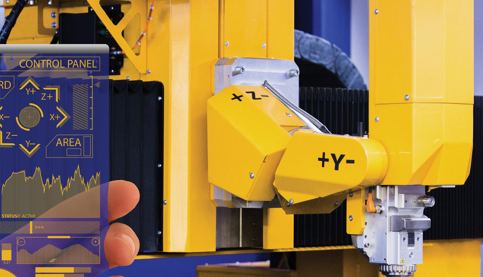
Wireless products for these functions are often compatible with various standards. Consider wireless networking USB sticks that impart remote connectivity to industrial PCs. Some include options for WLAN and 4G/3G/2G mobile communications. The sticks work on mobile robots and automated guided vehicles (AGVs) and an
array of other types of equipment needing wireless communications with a central controller or supervisory control and data acquisition (SCADA) system. Users can even monitor drive-based diagnostics for better preventive maintenance based on real-world application data containing information about the frequency of events.
Mobile machinery in agriculture, construction, and amusement-park installations have borrowed many smartfactory structures to impart autonomous capabilities to designs that once need one or more operators. Today’s off-theshelf automation controllers in such settings can impart the wireless and safety technologies necessary to protect personnel and communicate with existing computer systems.
5G in particular holds promise for manufacturing operations that might benefit from cloud connectivity, because it has the needed bandwidth and stability for production grids — especially where it’s realized as a campus network. But because there are usually network connections available on all machine infrastructures, some don’t anticipate widespread 5G-based industrial networking anytime soon. That hasn’t stopped component and system suppliers from preparing for the eventuality of 5G in industrial settings.
In fact, those priming for 5G technology adoption predict a concurrent expansion in augmented reality, virtual design, and AI.
With the exponential increase in speed, many expect processing times up to
motion control handbook
68 DESIGN WORLD — MOTION
HMI capabilities constituting IIoT functions include realtime supervision as well as advanced event logging and triggering, diagnostics, and additional enterprise-level monitoring.
Predict Machine Failures Before They Happen

Predictive maintenance enables machine controllers to monitor machine, production, and operator actions against expected outcomes. Out-of-tolerance events and inconsistent behaviors signal to the operator that maintenance will soon be required, allowing maintenance to be scheduled before the failure occurs, outside of normal production hours.

Servo systems from Mitsubishi Electric have failure prediction modes and include sophisticated algorithms to compensate and alert for specific impending failure modes such as:
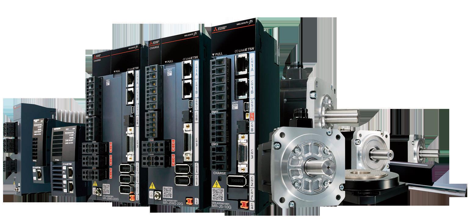

• Friction failure prediction
• Vibration failure prediction
• Total distance failure prediction

LEARN MORE us.MitsubishiElectric.com/fa/en ©2023, Mitsubishi Electric Automation, Inc.
10 times faster than what what’s currently possible with industrial 4G systems. In fact, wireless 5G technologies are capable of supporting realtime control by an external server over complex processes — to execute processes as complicated as 3D printing, for example.
Ethernet continues expansion in motion designs
Industrial Ethernet-based protocols continue to overtake traditional fieldbuses for the messaging of data in automated installations … and in fact, Ethernet-based protocols are now employed in more than 40% of industrial networks. It’s true that some fieldbuses are more reliable than legacy Ethernet offerings that are nondeterministic, but Ethernet speeds lead. More specifically, some old bus systems only have data rates of 1 to 20 Mbit sans realtime capabilities, so have slowly lost market share to Ethernet-based options having rates of at least 100 Mbit. Of course, bus protocols are sufficient for many simple industrial tasks, so will see continued use for decades to come.
Ethernet data rates support tracking and processing of data in realtime. Plus unlike fieldbus and device networks necessitating various physical layers, Ethernet works off one … and now, Power over Ethernet (PoE) mentioned earlier lets design engineers make further use of that single physical layer.
Especially at the intersection of IIoT and motion control, PoE connections lead. It was one difficult to get energy sufficient to power a motor from PoE connections … but the rapid adoption of higher-power IEEE standards in industrial Ethernet switches is supporting expansion here. The 802.3at standard for example provides 25 W of power to connected devices — which is enough to run a NEMA-14 step motor at full power. Some integrated motors for such arrangements accept power and communications via one of two standard Ethernet cables (RJ45 or X-coded M12) and support common networking protocols such as Modbus TCP and EtherNet/IP.
In fact, Ethernet-based connectivity is often in the form of EtherNet/IP. This application-layer protocol allows communication between controls and I/O; certain adaptations allow synchronized and deterministic multi-axis motion control.
Also seeing dramatic adoption is Serial Realtime Communications System (SERCOS) III employing industrialEthernet cable to connect drives, motion controllers, sensors, I/O, motors, and other actuators. With SERCOS III, deterministic bidirectional realtime motion and control communication is possible. Still other protocols capitalizing on Ethernet advantages include Ethernet for Control Automation Technology (EtherCAT), PROFINET, and CC-Link.
Some supplier ecosystems incorporate logistics, IT systems and security, networking, and cloudconnectivity solutions. Separate factories and their components (including workpieces and other physical objects as well as various data) are part of a larger network.
Such comprehensive networking and data management is spurring new business operations based on big data and universal cloud applications.
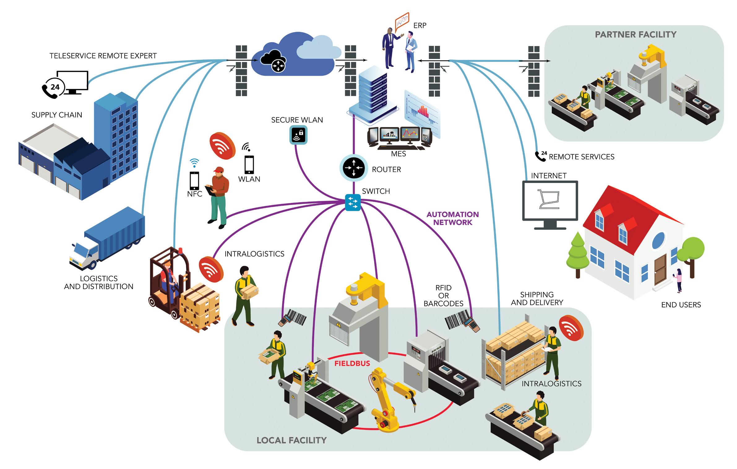
motion control handbook 70 DESIGN WORLD — MOTION 8 • 2023 motioncontroltips.com | designworldonline.com

Approaches to edge computing
Edge computing in motion system design refers to systems with distributed electronics that locally collect, store, analyze, and act upon with unrivaled speed. A related industrial-network structure brings cloud-computing capabilities down into the furthest reaches of the factory-floor via nodes and networks. Called fog computing, this distributed intelligence as well

as data processing out at a design’s most distal device locations (before data heads onward) have been available for some time. But devices with more computing power than in the past now allow unprecedented local preprocessing and predictivemaintenance functions … plus holistic views of processes for iterative design optimization.
The actuators, sensors, and other edge devices so fundamental to edge computing are supported
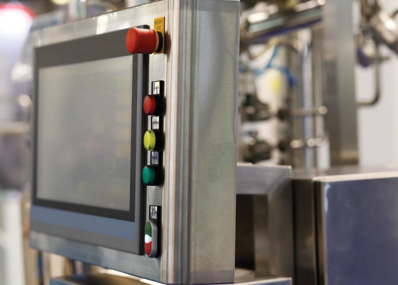
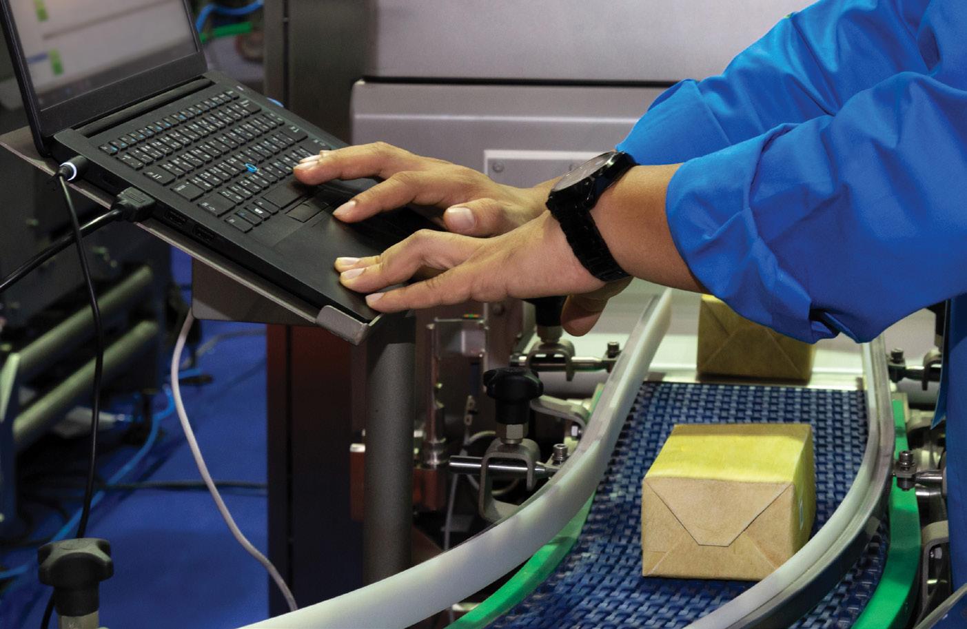
by gateways and controllers with dedicated connectivity functions. These sensing and actuating components are located near machines’ end effectors and active axis areas, which is why they are called edge devices — and in many cases (though not always) they use their logic resources to process speed, position, volume, throughput, and other data before sending it onward to controls, the cloud, or onsite servers and other
IT infrastructures. In contrast, many industrial-component suppliers use the term edge computing to primarily refer to the aforementioned gateways and controllers involved in data collection, analysis, and factoryfloor feedback in realtime. In this context, the edge is that of the factory at its border with MES, ERP, and higher-level enterprise systems.
motion control handbook
Some HMIs can directly connect with remote I/O components. That simplifies integration for what’s called edge computing in automation.
Image: Gumpanat Thavankitdumrong
From fractional to 2000 HP, Yaskawa low voltage industrial drives cover all of your application needs with an array of features that improve your operations.
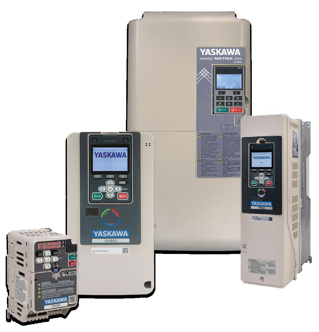
ü Intuitive Mobile-Friendly Interaction


ü Fast Connection to Any Major Network Protocol
ü Safety - Standard
ü Best-in-class Efficiency
And don’t forget about everything else Yaskawa provides you with.
ü World-Class Quality and Reliability
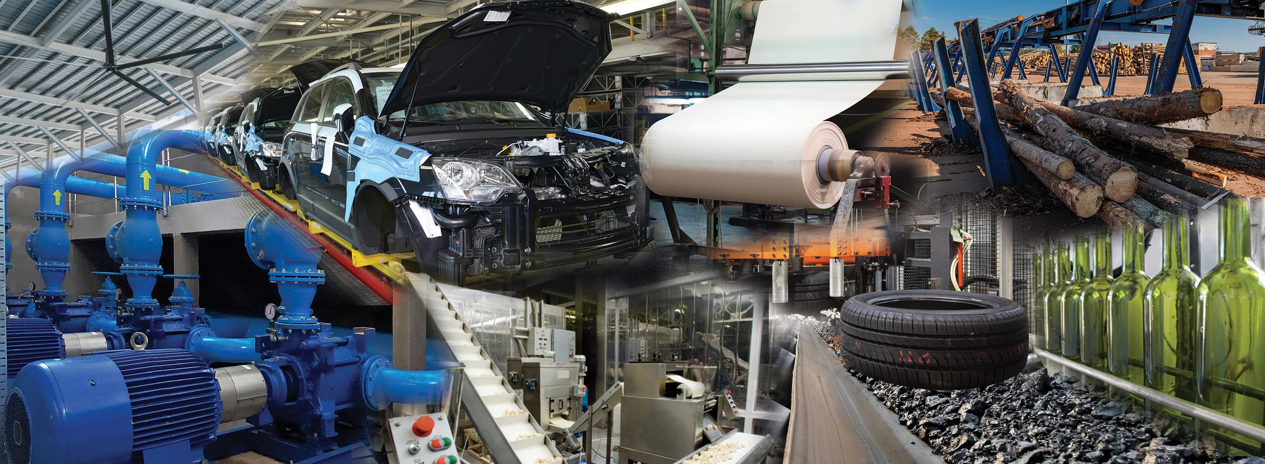
ü Award Winning Customer Service
ü Product Lifetime Training
ü Free 24/7/365 Technical Support
Want to have all of that working for you? Contact Yaskawa today.
MORE INFORMATION:
Yaskawa America, Inc. 1-800-YASKAWA Email: info@yaskawa.com | yaskawa.com SUSTAINABLE, FLEXIBLE, EASY THE STANDARD IN INDUSTRIAL DRIVES
FOR
https://go.yaskawa-america.com/yai1480
SHOCK AND VIBRATION BASICS
Vibration in industrial machinery often originates from imbalances inherent to motors, gearboxes, and other turning components that excite natural frequencies.

Shock and vibration dampers are some of the most common devices used to control vibrations in such systems by avoiding the structures’ natural frequencies during operation. Adding mass with heavy bases or mounting machines into steel or concrete flooring is one approach. In applications where this is not possible or sufficient, vibration-isolating components and other passive dampers can absorb or attenuate vibrations. Here, the components bear the whole machine weight to shift excitation off the natural frequency.
Shock and vibration mitigation
Some typical shock and vibration mitigation components include springs and rubber bumpers. These components are effective at slowing or stopping loads, but they mostly absorb the kinetic energy from the load and introduce it back into the system as rebounding, or “bouncing” of the load.
Pneumatic cushions are similar to shock absorbers in their ability to convert kinetic energy to thermal energy. But because air is compressible, their stopping forces are non-linear, increasing sharply at the end of the stopping stroke. Dashpots can also be used to slow and stop loads, but they also rely on air and provide non-linear resistance, with the stopping force peaking at either the beginning or the end of the stroke (depending on whether the device is used in “push” or “pull” mode).
motion control handbook
74 DESIGN WORLD — MOTION 8 • 2023 motioncontroltips.com | designworldonline.com
The electrification and automation of farm equipment have caused some convergence of motion-control and automotive shock-absorber applications. Image: Scharfsinn86 | Dreamstime
increases rapidly, and this heat (thermal energy) is then expended to the outer body of the shock absorber and the surrounding environment.
Dampers are another type of vibration mitigation component. Dampers are components that counteract and often isolate the vibration source from the rest of the design or machine to prevent its propagation of mechanical oscillation.
Passive vibration mitigation includes passive isolators such as closed-cell foam slabs, metal coil or wave springs, wire rope isolators, and rubber machine mounts. These reduce system natural frequency to less than that of excitation frequency. And just to be clear, traditional springs and rubber have near-zero damping capabilities.

Industrial shock absorbers provide a relatively linear reaction force throughout the entire stopping stroke, without rebounding or bouncing at the end of deceleration. This lack of bouncing also allows shock absorbers to provide faster stopping times than other damping systems. The result is fast, smooth, and predictable deceleration of the load.
The basic design of a shock absorber includes a double-walled cylinder, a piston, and a return mechanism for the piston. The inner cylinder is filled with a noncompressible fluid, such as hydraulic fluid or oil, and has orifices located at exponential intervals.
When the load makes contact with the piston rod, the piston pressurizes the fluid and forces it through the orifices. As the piston moves through its stroke, the orifices are closed off one-by-one. This ensures that pressure inside the cylinder remains constant and provides a linear stopping force for the load.

As the fluid is pressurized and forced through the orifices, its temperature
Precision passive isolators include negative-stiffness isolators, which decrease system natural frequency upon loading via a kinematic linkage of beam columns and springs, typically stacked in series for tilt, horizontal, and vertical motion.
In fact, many isolators do impart a small amount of damping. Some (including wire-rope isolators) also attenuate shock impact at sudden move ends, hard stops, and collisions without recoil — on conveyor e-brakes or axis stroke ends, for example.
In contrast with isolators, passive dampers (such as material slabs and mechanical linkages) change the kinetic energy of vibration into heat. Passive damping usually employs viscous fluids, viscoelastic materials, piezo elements, or simple magnetics.
Active vibration mitigation

Active dampers include an array of electronically controlled force cancellers that employ a power source, sensors, and actuation to counteract vibration with disruptive interference that is out of phase with the source vibration. These include:

• Shocks containing magnetorheological fluid that stiffen to solid with controllable
WAY


• Enhance operator and machine control through the entire range of motion without excess strength

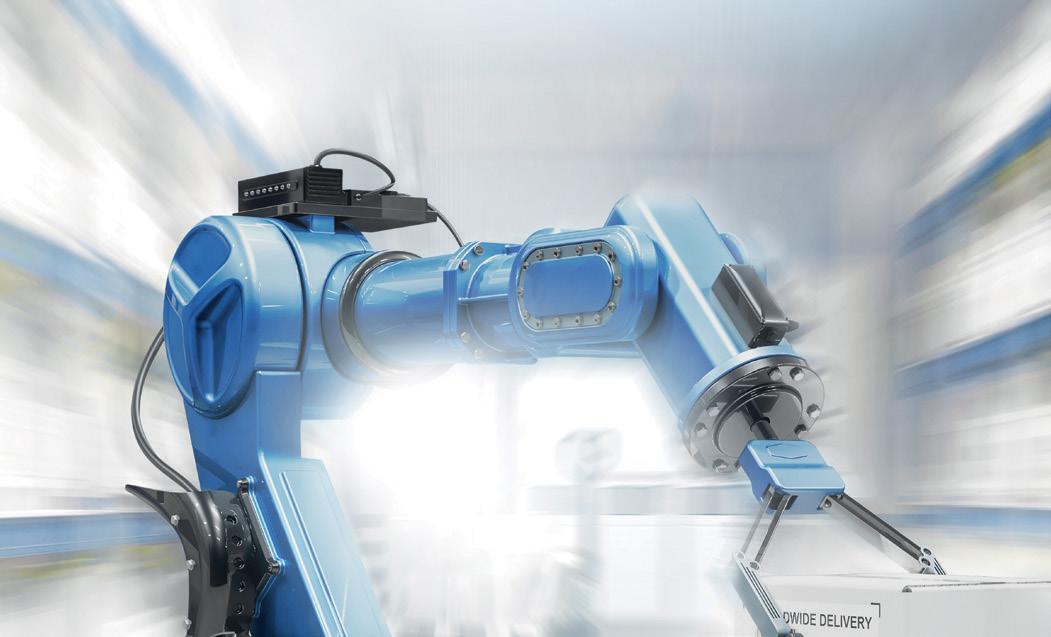
• Perfect support of muscle power with forces from 2 to 2,923 lbs.
• Stainless steel options for wash down and sterile environments


• A variety of accessories allows for universal application

shock & vibration mitigation
ACE Controls · Farmington Hills, Michigan www.acecontrols.com
75 DESIGN WORLD — MOTION 8 • 2023
INDUSTRIAL GAS SPRINGS ARE THE SMART
TO LIFT AND LOWER
yield strength under an applied magnetic field in milliseconds
• Powered piezoelectric elements affixed to the design frame at critical points to execute active countermotions and address vibration (usually detected by acceleration sensors) and under the control of a DSP.
Passive vibration damping in mechanical formats include tuned-mass dampers that affix to machinery or structures to damp narrow frequency bands of vibration. Other options for passive mechanical damping are friction and piezoelectric action prompted by simple resistive shunt.
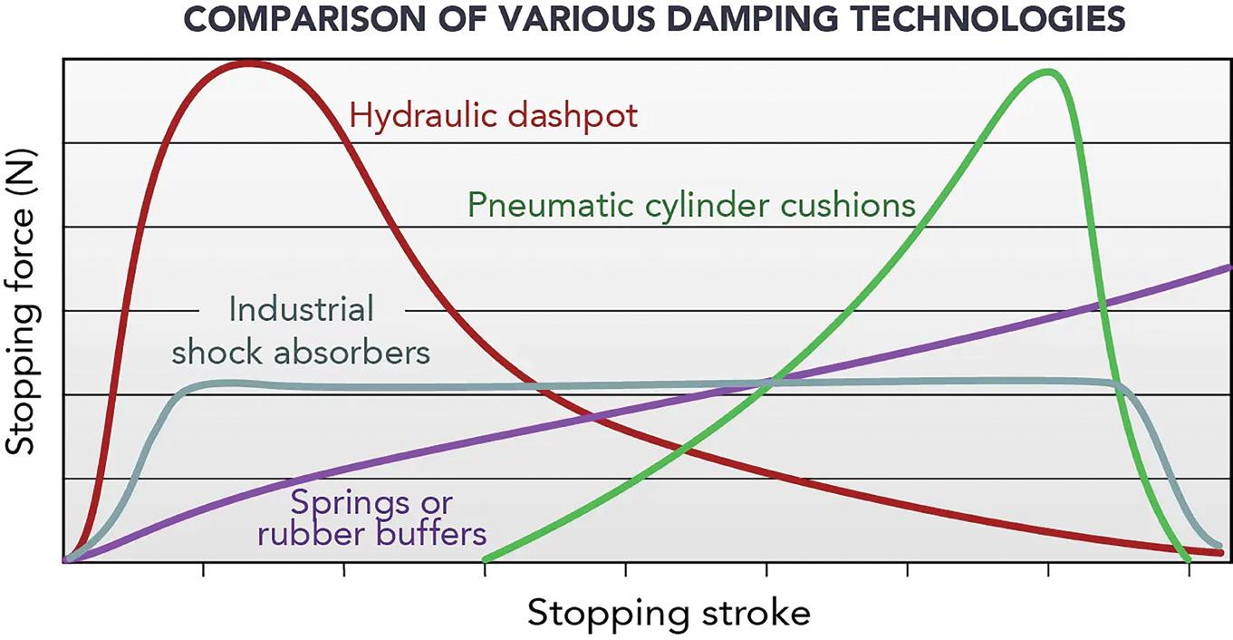
Passive vibration mitigation in fluidpower formats include hydraulic mounts, air springs, and bladders to isolate and damp industrial machines and other moving equipment. Passive air tables are another iteration, though increasingly displaced by other technologies. Gas springs (of the piston-type plunger design) act as kinematic holds.
Many pneumatic dampers have a similar structure — with a cylindrical chamber containing a piston and compressed air behind it — though work on moving axes. Oil dashpots employ a contained volume of fluid to resist motion with viscous friction to damp (though not isolate) vibration.
There are also passive vibration mitigation in elastomeric material formats — which offer simplicity in format and application. Foam slabs isolate well though lack durability. Rubber and neoprene excel at isolation but not damping.
Reducing vibration in step motors
Consider one specific vibration-mitigation example. With each discrete step that a stepper motor makes, the inertia of the system causes the motor to slightly overshoot (or undershoot) the intended step angle. The motor then oscillates or rings until it finally settles at the commanded position. If the frequency of these step-bystep oscillations is at or near the motor’s natural frequency, the motor’s settling time will increase, causing vibrations and audible noise. This is referred to as resonance, and if it becomes severe, it can cause the motor
to lose steps or even stall. There are several methods to reduce resonance in a step-motor system, with the simplest method to change system inertia. There are two ways to do this — by adding a mechanical damper between motor and load or by adding a gearbox to the system. Mechanical dampers for stepper motors range from simple elastomer rings that absorb and dissipate vibration energy, to tuned mass dampers, which are designed to match and counter the natural frequency of the system.
The addition of a gearbox provides two benefits. First, it decreases the total system inertia by decreasing the load inertia. (Recall that when a gearbox is used, the load inertia is divided by the square of the gear ratio). And when power is transferred from the motor through a gearbox, the motor has to rotate faster for a given output speed to the load, so there’s less chance that the motor will operate at or near its natural frequency.
The stepper drive’s control method can also affect the amount of vibration that the motor experiences. Case in point: Operating a motor with microstepping control gives the benefit of smaller torque variance with each step, because the buildup and decay of current in the windings is more gradual. Even though overshooting (or undershooting) is still possible with microstepping, it will be less significant than with full-step operation, so settling
time and vibrations will be lower. Five-phase stepper motors also have smaller step angles than typical two-phase motors. As with microstepping, the smaller step angle means less current is required for each step, so any vibrations that occur are less severe. Plus with more phases (five versus two) contributing to output torque, the motor experiences lower torque ripple, and in turn, fewer vibrations.
The special case of gas springs
Gas springs, also called gas dampers, tension springs, gas-pressure springs depending on the setup and context, are compressed-air or oil cylinders that install in motion designs to damp forces and return kinematic linkages and more complicated assemblies to default positions. Gas springs work through a piston on the end of a rod that protrudes from a steel cylinder body; usually compressed gas (often nitrogen) within the cylinder exerts force on this piston to reassume and maintain set positions. Nitrogen is common here because it’s inert and nonflammable. In such designs, oil or grease between the piston and other contacting parts minimize friction. In fact, the small amount of oil in these gas springs serves another function — to further damp and gently decelerate gas springs during full extension or compression. Some setups even include a fine hole in the piston for damping that’s still slower than with other designs; such
motion control handbook
76 DESIGN WORLD — MOTION 8 • 2023 motioncontroltips.com | designworldonline.com
Most damping devices exhibit non-linear stopping force, which causes shocks at the beginning or end of the stopping stroke. Shock absorbers, however, provide nearly constant stopping force throughout the entire stroke.
slow-damper springs are common on safety gates and doors.
In contrast, extended-reach gas springs usually leverage telescoping mechanisms pairing multiple cylinders on one rod; then the smaller cylinder extends from within the larger cylinder. Consider one particularly long-stroke application: Passive heave compensators — systems on ships or offshore oil-rig systems that reduce the effect of waves on engineered structures — use gas springs with strokes to many meters long.
Still other gas-spring applications include those for medical beds and hoists; industrial equipment such as machinetool presses; off-highway and automotive equipment for hatches, hoods, and covers; office equipment and furniture; and general strut and support applications. Fast-acting gas springs find use in weaponry and aerospace design. Specific variations include gas springs with standard or fixed-height
cylinders; spindle-only designs; and cable, return, adjustable auto-return, nonrotating, stage, and multi-mode cylinders.
No matter the iteration, gas-spring extension force — a value that usually ranges from 1 to 5,000 N — depends on piston-rod cross-section multiplied by fill pressure. Manufacturers commonly express extension force with two values — for rod extension and rod retraction — at normal ambient temperature and with the piston rod pointing downward. (Note that typical ranges are only those most common; some gas-spring applications in heavy industries use gas springs delivering several hundredthousand Newtons cases.) Other gas-spring definitions include two pull-in forces — at rod extension and rod retraction — and overall friction force. These values depend on the gas spring’s gas and damping-oil volumes. Various nozzle orifices and oil quantity allow control of push-out and push-in speed.
If design parameters are unknown, look for manufacturers capable of prototyping — especially for designs requiring an exact force that’s hard to pre-estimate — as in lifting a frame in a set time, for example. Here, some manufacturers sell prefilled cylinders sporting bleed valves. Then installers can bleed gas from the cylinders after system setup to get the correct forceacceleration actuation profile. The only caveat here is that if too much gas is bled, the assembly will need a new spring. That’s why OEM-level quantities of gas springs justify pre-engineered cylinders with preset pressurization. Or gas springs can offer full in-design adjustability via bleed valves and movable-endstop pressurization mechanisms, Bowden cables, knobs, and more. Some emergency-use gas springs also employ gas-generator cartridges that resemble those in airbags.
MADE IN THE U.S.A. SHOCK & VIBRATION SOLUTIONS NEW! STANDARD PRODUCTS GUIDE NEW SITE OVER 600 PARTS 800.838.3906 sorbothane.com Sorbothane_DesignWorld_Ad_12-2022_r2.indd 1 12/19/22 9:13 AM 77 DESIGN WORLD — MOTION shock & vibration mitigation
RoboBusiness brings together the brightest minds in robotics to better engineer the future of robotics. Whether you’re interested in machine learning, motion control, sensing, development tools, software or legged robots, these talks will have something for you. Featuring keynote speakers from some of the leading robotics groups, including:


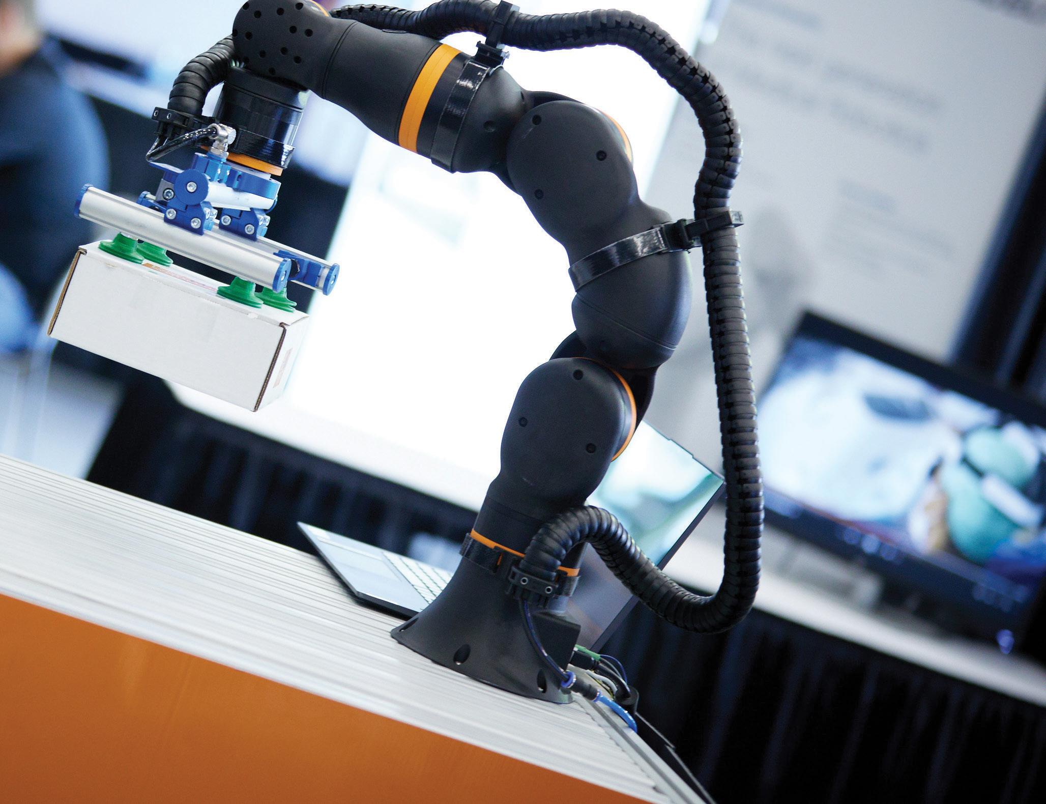

Driving Business. Identifying Opportunities.


 Hani Abouhalka Johnson & Johnson MedTech Je Cardenas Co-Founder & CEO
Ken Goldberg UC Berkeley
Jonathan Hurst Agility Robotics Ted Larson OLogic
Je Linnell Formant
Dave Rosa Intuitive Geordie Rose Sanctuary
Sarah Schnickel John Deere
Pras Velagapudi Agility Robotics
Hani Abouhalka Johnson & Johnson MedTech Je Cardenas Co-Founder & CEO
Ken Goldberg UC Berkeley
Jonathan Hurst Agility Robotics Ted Larson OLogic
Je Linnell Formant
Dave Rosa Intuitive Geordie Rose Sanctuary
Sarah Schnickel John Deere
Pras Velagapudi Agility Robotics
AD INDEX
volume 9 number 3
SALES
Ryan Ashdown rashdown@wtwhmedia.com 216.316.6691
Jami Brownlee jbrownlee@wtwhmedia.com 224.760.1055
Mary Ann Cooke mcooke@wtwhmedia.com 781.710.4659
Jim Dempsey jdempsey@wtwhmedia.com 216.387.1916
Mike Francesconi mfrancesconi@wtwhmedia.com 630.488.9029
LEADERSHIP TEAM
Publisher Mike Emich memich@wtwhmedia.com 508.446.1823
Managing Director Scott McCafferty smccafferty@wtwhmedia.com 310.279.3844
Jim Powers jpowers@wtwhmedia.com 312.925.7793
Courtney Nagle cseel@wtwhmedia.com 440.523.1685
EVP Marshall Matheson mmatheson@wtwhmedia.com 805.895.3609
CFO Ken Gradman kgradman@wtwhmedia.com 773.680.5955
79 DESIGN WORLD — MOTION 8 • 2023 motioncontroltips.com | designworldonline.com Ace Controls 75 ACS Motion Control 23 AllMotion 5 Automation Direct 1 Beckhoff Automation ............................................................ 66 Bodine Electric Company ...................................................... 20 Canon U.S.A. Inc 57 CGI Inc. 48 Chieftek Precision 15 Clippard BC CMT ...................................................................................... 26 Del-tron ................................................................................. 13 Diequa 55 Digi-Key Electronics 3 Dura-Belt 27 Encoder Products Company 65 Faulhaber .............................................................................. 59 GAM .................................................................................... IBC Harmonic Drive ..................................................................... 52 HEIDENHAIN CORPORATION 64 HELUKABEL USA 25 igus 7 iNTECH Power-Core 51 KHK USA Inc. ......................................................................... 61 Mitsubishi Electric Automation ............................................. 69 mk North America, Inc. 39 Motion 71 NB Corp 9 New England Wire & Tubing Technologies 33 PBC Linear ............................................................................. 17 PI (Physik Instrumente) LP ..................................................... 72 POSITAL FRABA 63 Pyramid, Inc. 29 Renishaw 36 Rotor Clip Snipe, 41 SEW-Eurodrive ...................................................................... 50 Sorbothane ............................................................................ 77 Stock Drive Products/Sterling Instrument 28 THK America, Inc. IFC Yaskawa America, Inc. 73 Zero-Max, Inc. 2
LUBRICATING TRACK-ROLLER GUIDES
Many track-roller linear guides necessitate lubrication at two different points in their assembly:
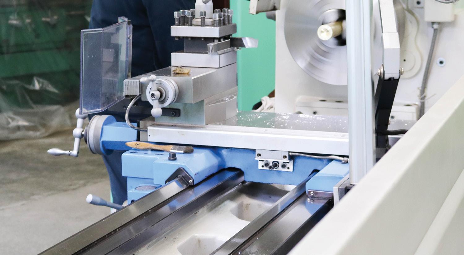
• Within the rolling-element rotary bearings at the heart of each track-roller wheel and
• Along the linear track-roller raceway. As with most any mechanical powertransmission devices, lubrication of these two critical areas extends the linear guide’s service life by minimizing or eliminating the corrosion of metal subcomponents as well as reducing friction and noise (and therefore wear).
Track-roller wheel-bearing lubrication: For the rolling-element rotary bearings at the heart of each track-roller wheel, industrialgrade mineral oil is most used for lubrication with lithium soap grease where suitable. (In fact, lithium-soap grease is sometimes also applied to the raceway for shipping.) For very hot settings or axes required to bear especially heavy payloads, extreme-pressure or EP additives can prevent direct contact of mating wear surfaces as well as resist the detrimental effects of sliding surface contact. As with any component that’s at its core a metal rolling-element rotary bearing, grease filling mustn’t exceed the recommended percentage of bearing’s free internal volume. Track-roller raceway lubrication: The raceways of track-roller linear guides often obtain lubrication via wipers pre-integrated into the assembly’s carriage in some way. Where exacting lubrication parameters are essential to the machine axis’ operation, some manufacturers allow for carriages
to be specified with lubrication wipers or oil designed for a given application — for example, with metal shields to ensure the delicate wiper elements withstand operation on machine-tool equipment. Some manufacturers offer engineered caps to encase and therefore protect wheels while concurrently delivering lubrication to the raceway upon each axis stroke.
Often, the lubricant applicator itself takes the form of a felt cuboid loaded with oil. These rectangular prisms are either preloaded with enough oil to last the life of the machine or assembled to the carriage so that the end user can reload them with oil via a lubrication nipple during regular servicing. Though exceptions abound, small track-roller assemblies are more likely to be lubricated and sealed for life, while those destined to bear heavy loads often feature means and hardware to allow relubrication.
In fact, such servicing should take place at lubrication intervals defined by the linearcomponent supplier. While the exact interval may require definition by qualitative test runs, particularly dirty settings always necessitate more frequent and copious lubricant. Otherwise, raceway fretting, corrosion, and other issues will develop.
One last note: Where a piece of linear-motion equipment is destined for use in the food and beverage industry and there’s a possibility of incidental food contact,
lubricant used on the raceway should be National Sanitation Foundation (NSF) Intl. H1 lubricant.
Grease versus oil track roller linear guide lubrication
The most suitable lubricant for the internal elements of a track-roller wheel depends on the bearing type it contains; the application’s parameters; how the track-roller linear guide is integrated into the larger machine; and the accessibility of the linear guide for potential relubrication.
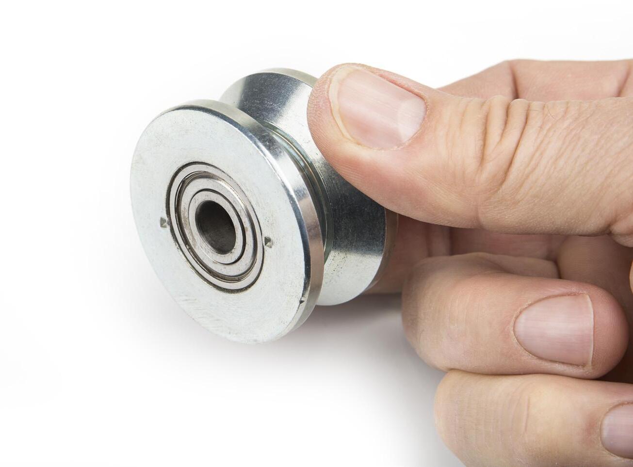
Oil lubrication can creep into and carry heat out of contact zones; the latter is especially important on linear axes needing to make quick strokes. Oil also tends to offer exceptionally low friction and transport debris away from the working (contact) zones of the guide assembly. The main drawback of using oil is the way in which it necessitates special sealing.
In contrast, grease lubrication carries no debris or heat out of contact zones and can in some cases get pushed out of the very contact zones it’s meant to protect. However, grease requires almost no special retention elements. In fact, it tends to protect wheel assemblies in particular against the ingress of debris. It’s also a leading choice where an axis must deliver a long service life with little to no servicing. Where needed, ducts for the infrequent changing of grease may be included in the carriage assembly.
A third option for especially hot, corrosive, or otherwise challenging applications is track-roller carriage elements sporting assembly elements made of solid lubricant or oil-impregnated materials to wipe over or intermittently daub working surfaces with lubricating substances.
motion control handbook
Consider a representative track-roller wheel with caged ball-bearing arrays for all the contact points at which lubricant is needed. Within the subcomponent, an angular-contact design supports both radial and axial forces at four locations on each ball; then the wheel O.D. bears load at two contact locations with the linear raceway. Image: Dreamstime • Maxopphoto
80 DESIGN WORLD — MOTION 8 • 2023 motioncontroltips.com | designworldonline.com
The bearing elements within track-roller wheels require lubrication that’s much like that for other rotary bearings.
Everything Between the Motor and the Actuator
Simplify the process of designing and building your own Cartesian systems with GAM’s Linear Mount Products
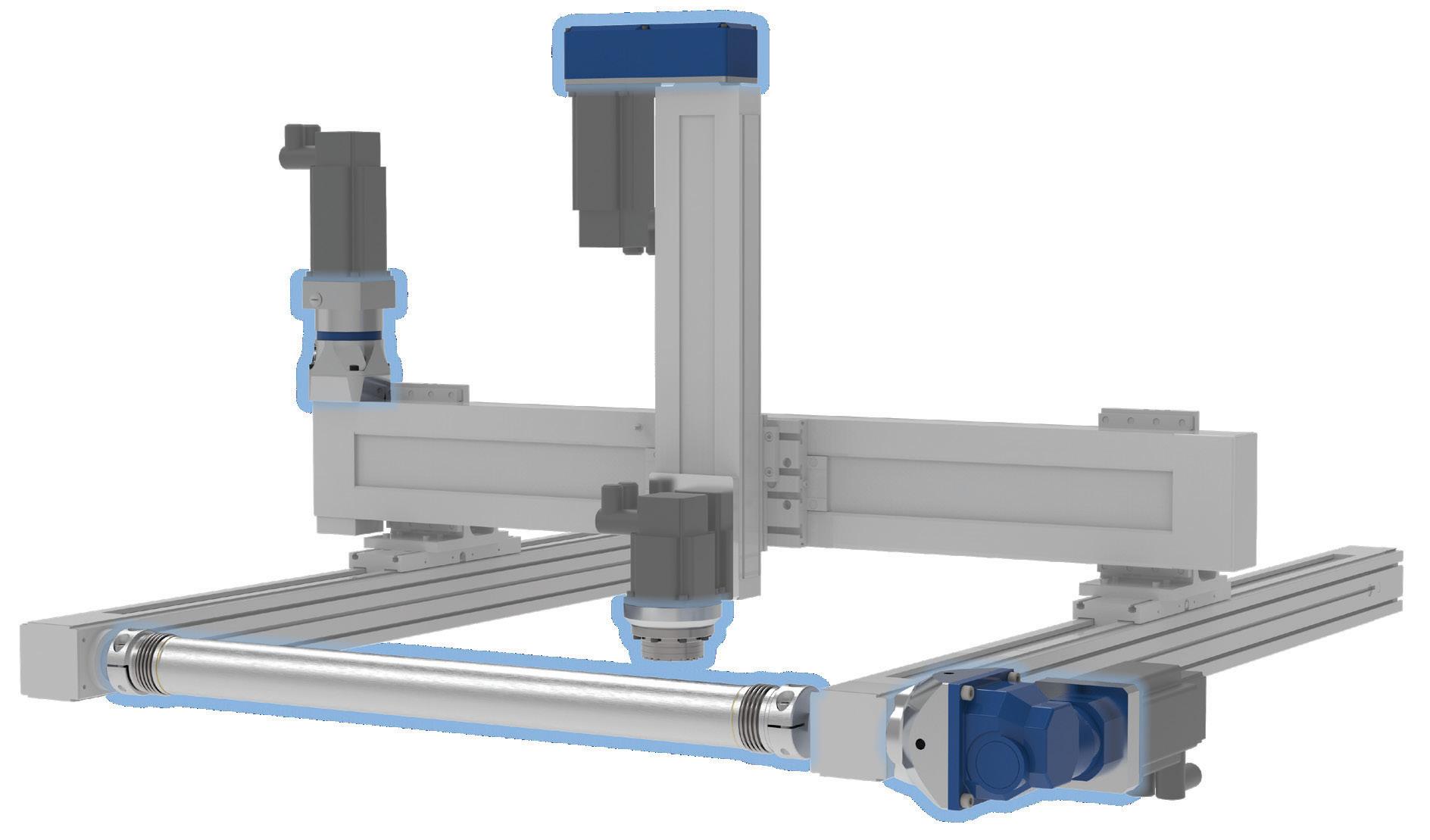
Choose from a variety of inline and right angle gearboxes that connect directly to actuators, along with the necessary mounting adapters and couplings, to transform individual products into an integrated solution. ®
www.gamweb.com/linear | info@gamweb.com | 888.GAM.7117 Build your own Cartesian System with GAM Linear Mount Products
Parallel mounting kits save space by mounting the motor parallel to the ballscrew actuator EPL-U Inline gearbox with hollow or shaft output and custom adapter for easy mounting to linear actuators WDS Bellows and elastomer style distance couplings, up to 6 m long, connect actuators without additional shafts DL-DC Right angle Dyna-Lite gearbox with hollow output design for easy mounting to linear actuators. Includes output adapter tailored to the actuator GSL Theta axis with zero-backlash strain wave gearbox includes output flange or thru-hole for tooling and integrated motor mount
•Resolution ≤5 mV
•Accuracy ±0.25% of full scale
•Real-time adjustable PID control
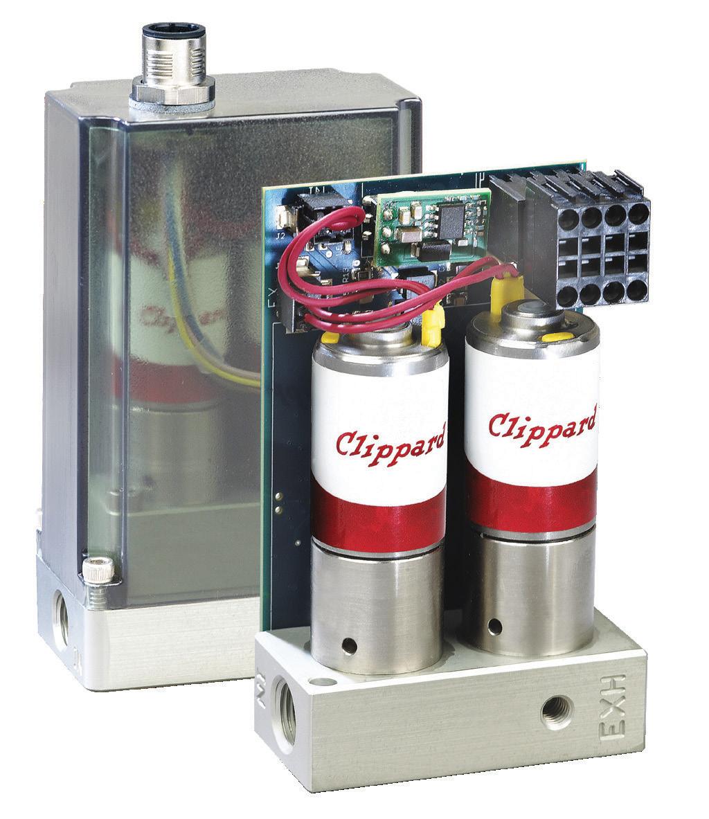
•Integrated 0 to 10 VDC, 4-20 mA signal, or 3.3 VDC serial communication
• 0 to 10 VDC feedback pressure monitor
•Virtually silent
•No integral bleed required
•Multiple pressure ranges from vacuum to 150 psig
•2.7 to 65 l/min flow control
Take Control with Cordis
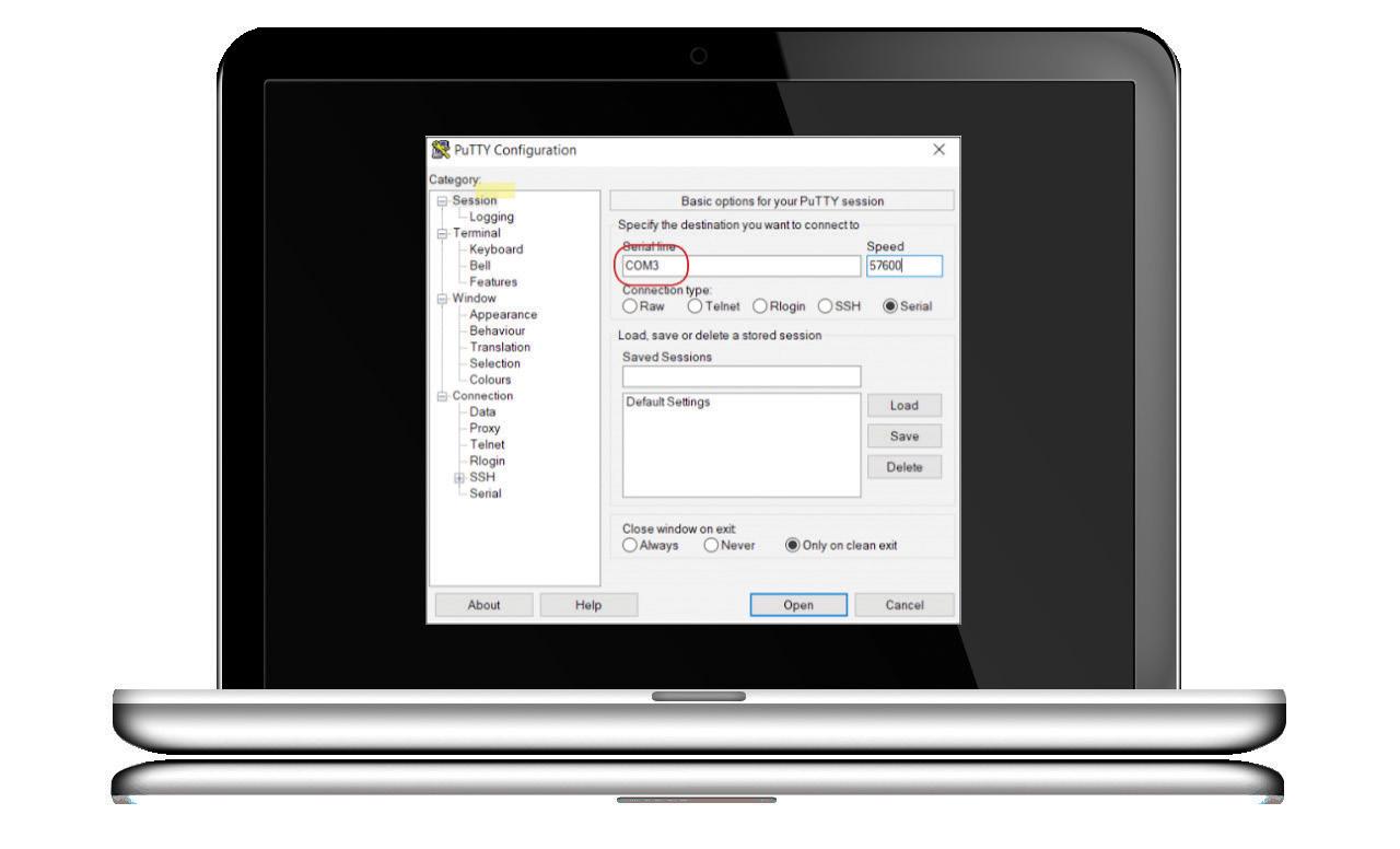

The future of proportional control has arrived— and it’s digital. The Clippard Cordis is a revolutionary microcontroller primed for escape velocity from a proportional control market that has grown stagnant.
With unparalleled performance and flexibility not possible with current analog proportional controllers, the Cordis makes everything from calibration, to sensor variety, to future development opportunities more accessible and less complicated.
Contact your distributor today to learn more about how the Cordis can provide precise, real-time control for your application, or visit clippard.com to request more information.
877-245-6247
Precise, Linear Digital Pressure Control
CINCINNATI
• BRUSSELS • SHANGHAI
ELECTRONIC PRESSURE REGULATION
