8 minute read
Applying couplings in motion designs


Couplings connect rotating shafts in equipment powered by electric motors and other drives. All transmit torque and angularvelocity. Flexible variations compensate for misalignment. Many of thelatter even address vibration and improve system dynamics.
Design considerations include machine or installation construction and backlash, torsional stiffness, damping, inertia, torque ratings, maximum rpm, size, misalignments, ease of installation, robustness, and cost.
For power transmission (as in motors for pumps and large materialhandling setups) common choices are gear, disc, elastomeric tire, grid, jaw, and Oldham couplings because of their ruggedness and ability to transmit very large torques.
Motion-control applications (as for axes employed in precise positioning of loads, for example) typically employ couplings capable of oft-more modest but far more precise torque transmission. These include curved-jaw, beam (slit), bellows, disc, and other zero-backlash couplings.
Any misalignment that couplings accommodate should be what’s otherwise unavoidable even after proper machine-axis squaring and installation adjustments. That’s because misalignment (manifest as parallel, axial, and angular misalignment) degrades efficiency, induces bearing wear, and excites machine natural frequencies.
To review, the maximum amount of angular misalignment for which a coupling can compensate is expressed in degrees.
Parallel misalignment between the shafts a coupling connects is expressed in inches or millimeters.
Axial misalignment is also a length value; it’s the maximum permissible spread between coupled shafts — and in fact, a misalignment permutation often most affected by thermal effects.
Flexible couplings for motion control are often less forgiving of misalignment than those for more straightforward power transmission and resolve it with specialty design features.
A related phenomenon and a coupling consideration specific to motion-control installations is backlash. In applications for strict power transmission, backlash is far less of a concern than that of efficient torque transmission — and actually a characteristic that (in normal moderate quantities) helps make some couplings in these settings more efficient and forgiving of misalignment.
In contrast, couplings on the outputs of steppers and servomotors are designed to prevent the lost motion that can degrade output-product quality or overall machine throughput.
Note there’s a difference between backlash (which is true mechanical clearance) and the torsional deflection or windup that all loaded rotary components exhibit. Most couplings for motion applications are inherently backlash free or preloaded to eliminate backlash — but they all have different torsional stiffnesses, which is sometimes a tradeoff for lateral flexibility.
PITFALLS TO AVOID DURING SELECTION OF COUPLINGS FOR MOTION
Design engineers often run into trouble when they neglect to account for environmental effects on couplings — particularly flexible couplings installed in gritty or caustic areas, vacuum environments, or places that are extremely hot or cold.
Beyond that and the common design considerations already listed, designers must account for dynamic forces to which a coupling will be subject. Steer clear of using published an axis’ gearset or motor peak-torque values for setting its coupling’s nominal torque rating. That’s because this approach usually makes for an assembly with an oversized coupling and an unnecessary inertial increase.
Designers should also avoid the application of a coupling type simply because it’s a familiar technology.
For example, beam couplings are extremely well known in industry, and they excel on axes transmitting moderate to light torque — as on leadscrewdriven motorized axes or where there’s a need for attachment of a precision encoder, for example.
Installation tip: With beam couplings, tighten one hub first and then (before tightening additional screws) rotate the coupling by hand to let it reach free length. Setting a beam coupling while it’s compressed or extended with shorten its life.
Some particularly demanding designs may necessitate a flexible coupling type that maintains higher torsional stiffness.
On the other hand, it’s also inadvisable to simply pick a coupling based on high torsional stiffness. Many flexible couplings have an inherent stiffness that exceeds application requirements for servo tuning and motion accuracy.
Specification tip: On any axis subject to jams, crashes, or emergency stops, safety couplings (though initially more expensive) are a better choice than standard servo couplings. The former can disengage to prevent damage and downtime.
Even in motion designs requiring high stiffness for the shortest possible response time (as in equipment for electronics manufacturing, for example) couplings with good damping characteristics often offer more effective optimization than more torsional stiffness. That’s because overly stiff couplings of many designs pose an unnecessary risk of fatigue.
Manage expectations: Not all servo couplings are meant to last as long as the machine. Where significant cyclical flexing to accommodate axis misalignment limits service life, couplings should be considered a wear item necessitating regularly scheduled replacement.
Couplings for servo applications usually connect precision drives to sensitive loads, so they cannot induce any error. That’s why servo couplings should be zero backlash — to prevent issues with timing and predictability (not to mention failures due to hammering on reversing axes). Couplings for servo applications must also have high torsional stiffness while imparting slight forgiveness of misalignment (within specifications) of rotating shafts … even while holding transmitted rpm steady to motor output rpm.
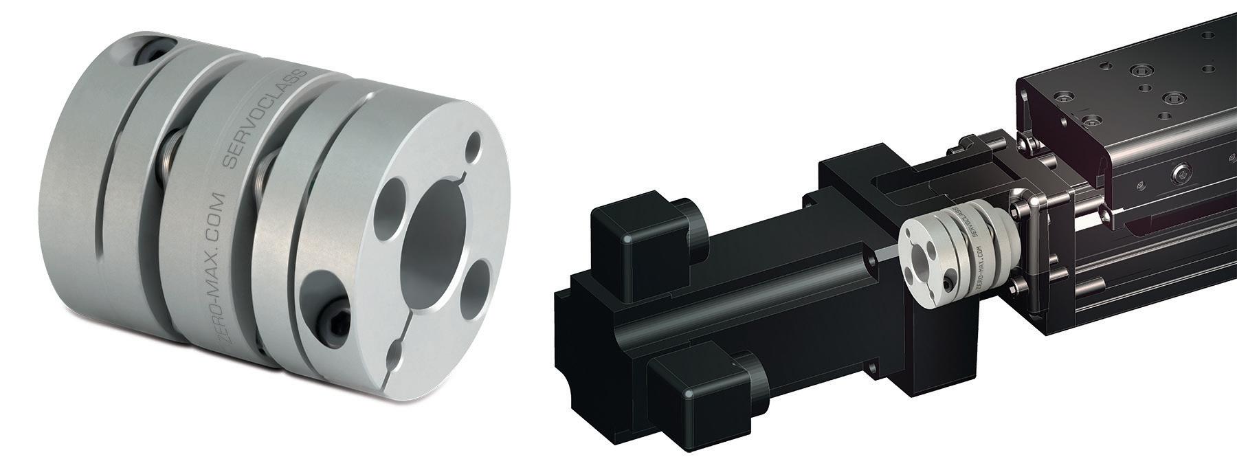
But these are just a couple servo coupling considerations. Consider a typical application for servo couplings — to connect a servomotor to a ballscrew. Here, couplings with low inertia let the axis deliver faster acceleration and deceleration without unnecessarily degrading overall system efficiency.

Bellows couplings with tapered press-fit connections simplify connection of precision drive components by eliminating the need to access clamping screws inside mounting flanges and housings. Instead, the two coupling segments can be moun to their respective shafts at the correct axial location, and the “plug-in” bellows connection is completed once the driving and driven component frames mount together. The bellows provides a slight preload to the mating engagement of the two segments — eliminating backlash. Image courtesy R+W America
In fact, couplings for servo designs must often compensate for subtle power-transmission issues to minimize errors down to 1 arc-min. or lower. That’s especially true where servo systems take the form of exacting positioning axes.
Here’s a more complete list of parameters to consider for proper coupling operation in such designs:
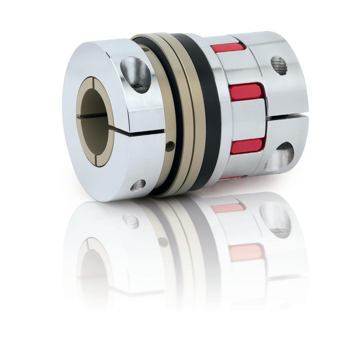
1. Coupling type: Couplings shouldn’t be the last motion component specified because proper servo-machine function relies on having a suitable coupling in place. Torsionally rigid options (ideal for motion designs) include specialty bellows couplings, rubber-jaw couplings, and disc couplings. Curved-jaw couplings have good damping characteristics to optimize performance of axes with quick acceleration and deceleration. Elsewhere, both disc-type couplings and certain bellows couplings excel on high-speed axes. Other offerings abound to serve other design objectives. One caveat on coupling type though: Never use rigid couplings to replace flexible servo couplings on axes where the latter seem to fail frequently.
Here, this issue is most likely insufficient alignment between the motor-output shaft and next component in the powertrain.
There’s sometimes a misconception that rigid couplings are exceptionally strong, so can address issues in such situations. The fact is that rigid couplings only work when shafts are perfectly aligned, because these couplings transmit to connected motion components (potentially extreme) forces that arise from misalignment.
2. Sizing for torque and speed: After specifying the coupling type, the design engineer must select a coupling size. This is heavily dependent on axis speed (rpm) as well as the levels of torque the axis must transmit and the service factor the application requires. Axes that transmit steady torque are simpler to specify; in contrast, axes that transmit variable torque need additional consideration. Here, define the application’s average operating torque and the peak torque. Also consider the parameters listed in “Ability to handle reversals” below.
One tip to avoid servo coupling oversizing: Quantify actual system requirements and base coupling selection on those values — and avoid defining a whole axis by the connected gearmotor’s peak torque output.
3. Stiffness: Along with exacting control of position, force, or output velocity, it’s often essential to maintain high efficiency. Couplings that exhibit windup or backlash degrade this efficiency because they must overcome load inertia every move cycle. This can be a significant drawback in some setups ... which is why (especially on axes employing rigid variations) couplings should be prevented from inadvertently functioning as flywheels.
Note that if a coupling’s torsional stiffness is insufficient, other system functions must compensate. One standard solution is to adjust PID controls and reduce servo gain, though that degrades system response and performance.
In contrast, excessive torsional stiffness compromises the ability of an axis to withstand quickly reversing loads. That’s because servo couplings with excessive stiffness can be brittle and prone to failure on demanding axes that must make frequent and sudden directional reversals.
Servo-application tip: Balance coupling characteristics for stiffness. Excessive torsional stiffness may induce premature failure. On the other hand, axes that must hold timing (as for positioning commands) benefit from incorporation of torsionally stiff couplings.
4. Inertia: As mentioned, this is an important parameter for a few reasons. Applications with particularly aggressive motion profiles rely on low servo coupling inertia most of all.
5. Damping capabilities: Disc couplings, certain bellows couplings, and high-gain rubbertype couplings are all options for couplingbased damping in servo applications.
In fact, the most demanding servo applications have in recent years spurred improved response frequencies ... but vibration (and hunting) arise with high gain settings on assemblies using torsionally stiff couplings. Visit couplingtips.com and search on “damping” for more on this issue and some solutions.
6. Shaft connections: Most servo couplings connect shafts with clamping or locking mechanisms (and not keyways). Though keyways are often offered as an option to prevent shaft slippage, the truth is that they can be a liability — adding concentrations of stresses in shaft connections, unnecessary cost, risk of imbalance, and other potential drawbacks.
7. Ability to handle reversals: Servo applications that must make quick directional changes require special consideration. Here, consider torque associated with system inertia starting and stopping. Service factors can often quantify the effect this value will have on assembly dynamics. Another aspect of reversing loads to consider is coupling-material fatigue. Keep in mind that some servo couplings that perform for years in regular applications with fail within weeks or sooner when forced to transmit power under reversing conditions.
8. Function to protect more expensive subcomponents: Though system failures are best avoided, couplings can be designed to protect the axis actuator or motor and gearbox by breaking if there is a machine crash or catastrophic overload. That’s especially useful in high-speed servo applications where drive-based current limits aren’t fast enough to address existing kinetic energy associated with the drivetrain and load upon a jam or sudden impact.
9. A realistic understanding of allowable misalignment: Flexible couplings for servo applications do accommodate misalignment. However, OEMs must be realistic about the level of permissible misalignment for a given axis — and specify assembly techniques and mounting that ensure levels that ever exceed the rating of the coupling. Otherwise, coupling or another component failure may occur.