COUPLINGS
Applying couplings in motion designs Couplings connect rotating shafts in equipment powered by electric motors and other drives. All transmit torque and angular velocity. Flexible variations compensate for misalignment. Many of the latter even address vibration and improve system dynamics. Design considerations include machine or installation construction and backlash, torsional stiffness, damping, inertia, torque ratings, maximum rpm, size, misalignments, ease of installation, robustness, and cost. For power transmission (as in motors for pumps and large materialhandling setups) common choices are gear, disc, elastomeric tire, grid, jaw, and Oldham couplings because of their ruggedness and ability to transmit very large torques. Motion-control applications (as for axes employed in precise positioning of loads, for example) typically employ couplings capable of oft-more modest but far more precise torque transmission. These include curved-jaw, beam (slit), bellows, disc, and other zero-backlash couplings. Any misalignment that couplings accommodate should be what’s otherwise unavoidable even after proper machine-axis squaring and installation adjustments. That’s because misalignment (manifest as parallel, axial, and angular misalignment) degrades efficiency, induces bearing wear, and excites machine natural frequencies. To review, the maximum amount of angular misalignment for which a coupling can compensate is expressed in degrees. Parallel misalignment between the shafts a coupling connects is expressed in inches or millimeters. Axial misalignment is also a length value; it’s the maximum permissible spread between coupled shafts — and in fact, a misalignment permutation often most affected by thermal effects. Flexible couplings for motion control are often less forgiving of
misalignment than those for more straightforward power transmission and resolve it with specialty design features. A related phenomenon and a coupling consideration specific to motion-control installations is backlash. In applications for strict power transmission, backlash is far less of a concern than that of efficient torque transmission — and actually a characteristic that (in normal moderate quantities) helps make some couplings in these settings more efficient and forgiving of misalignment. In contrast, couplings on the outputs of steppers and servomotors are designed to prevent the lost motion that can degrade output-product quality or overall machine throughput. Note there’s a difference between backlash (which is true mechanical clearance) and the torsional deflection or windup that all loaded rotary components exhibit. Most couplings for motion applications are inherently backlash free or preloaded to eliminate backlash — but they all have different torsional stiffnesses, which is sometimes a tradeoff for lateral flexibility.
PITFALLS TO AVOID DURING SELECTION OF COUPLINGS FOR MOTION Design engineers often run into trouble when they neglect to account for environmental effects on couplings — particularly flexible couplings installed in gritty or caustic areas, vacuum environments, or places that are extremely hot or cold. Beyond that and the common design considerations already listed, designers must account for dynamic forces to which a coupling will be subject. Steer clear of using published an axis’ gearset or motor peak-torque values for setting its coupling’s nominal torque rating. That’s because this approach usually makes for an assembly with an oversized coupling and an unnecessary inertial increase.
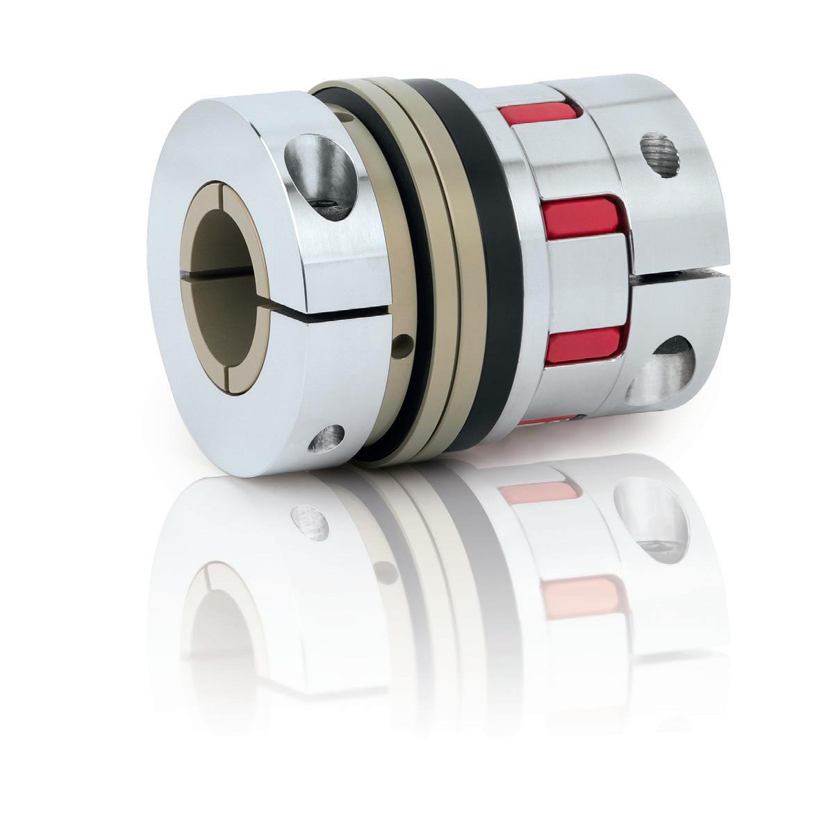
Bellows couplings with tapered press-fit connections simplify connection of precision drive components by eliminating the need to access clamping screws inside mounting flanges and housings. Instead, the two coupling segments can be moun to their respective shafts at the correct axial location, and the “plug-in” bellows connection is completed once the driving and driven component frames mount together. The bellows provides a slight preload to the mating engagement of the two segments — eliminating backlash. Image courtesy R+W America
motioncontroltips.com | designworldonline.com
8 • 2020
DESIGN WORLD — MOTION
41