5 minute read
Pitch line velocity in gearbox sizing


In gearbox sizing, it’s key to determine the required input speed in rpm and ensure that it doesn’t exceed the gearbox maximum-speed capability. But the linear velocity of the gear teeth known as pitch line velocity also plays a significant role in gearbox performance.
Pitch line velocity is measured at the pitch line of the gear, which is midway along the length of the gear teeth. For circular gears, the pitch line is more correctly referred to as the pitch circle — an imaginary circle that rolls without slipping when aligned with the pitch circle of the mating gear.

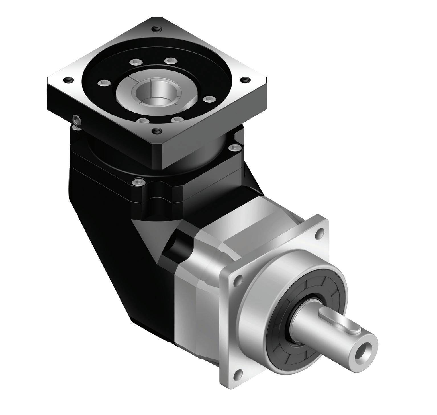
This AFXR series 90° helical bevel gearbox from Apex Dynamics features a short yet rigid housing and full compatibility with standard motor adapters.
Strictly speaking, pitch line is the correct term when referring to a linear gear rack, and pitch circle is the correct term when referring to a circular gear. However, the term pitch line is often used when discussing the equivalent linear velocity of a circular gear — as in pitch line velocity.
Pitch line velocity is a function of the gear’s pitch diameter and its rotational speed:

Where PLV = pitch line velocity (m/sec); d p = pitch diameter (m); ω = rotational speed (rpm) Pitch line velocity is important for gear design and selection for several reasons.
The American Gear Manufacturers Association standard 9005-D94 Industrial Gear Lubrication specifies that a gear’s pitch line velocity is one of the primary criteria for selecting gear lubrication.
Pitch line velocity also determines the contact time between gear teeth, which has a significant impact on the required oil viscosity.
High pitch line velocities are usually accompanied by light loads and short contact times, making low-viscosity oils suitable. However, low pitch line velocities are associated with high loads and long contact times, which make high-viscosity or even EP-rated oils necessary.
In addition to lubrication considerations, pitch line velocity also affects the load capacity and service life of gear teeth. The ability of gears to transmit the required torque for the desired operating life depends on the ability of the gear teeth to withstand bending stress. Tooth bending stress is determined according to the Lewis formula:

Where σ = Tooth bending stress (MPa)
= Tangential force on tooth (N) and P = Diametrical pitch (mm-1) F = face width (mm); Y = Lewis form factor
But as gear teeth come into initial contact, they experience greater stresses, based on the velocity of the gear. In order to account for these stresses, a velocity factor Kv was developed.
The velocity factor depends on both the pitch line velocity of the gear and the quality of the gear (Qv) and can be obtained from AGMA charts. This velocity factor Kv is used to modify the Lewis equation:

Thus the higher the pitch line velocity, the greater the bending stress on the gear teeth.
Note: The AGMA has developed an equation for bending stress that replaces the Lewis Form Factor with a geometry factor J and includes factors for other conditions that affect gear service life such as overload, load distribution, and mounting.
TECHNOLOGY DEEP DIVE: HELICAL GEARS
Helical gears and spur gears are two of the most common gear types and can be used in many of the same applications. Spur gears are simple and inexpensive to manufacture, but helical gears offer some important advantages over spur gears.
The teeth of a helical gear are set at an angle (relative to axis of the gear) and take the shape of a helix. This allows the teeth to mesh gradually, starting as point contact and developing into line contact as engagement progresses. One of the most noticeable benefits of helical gears over spur gears is less noise, especially at medium- to high-speeds. Also, with helical gears, multiple teeth are always in mesh, which means less load on each individual tooth. This results in a smoother transition of forces from one tooth to the next, so that vibrations, shock loads, and wear are reduced.
But the inclined angle of the teeth also causes sliding contact between the teeth, which produces axial forces and heat, decreasing efficiency. These axial forces play a significant role in bearing selection for helical gears. Because the bearings have to withstand both radial and axial forces, helical gears require thrust or roller bearings, which are typically larger (and more expensive) than the simple bearings used with spur gears. The axial forces vary in proportion to the magnitude of the tangent of the helix angle. Although larger helix angles provide higher speed and smoother motion, the helix angle is typically limited to 45° due to the production of axial forces.
The axial loads produced by helical gears can be countered by using double helical or herringbone gears. These arrangements have the appearance of two helical gears with opposite hands mounted back-to-back, although in reality they are machined from the same gear. Note that the difference between the two designs is that double helical gears have a groove in the middle, between the teeth, whereas herringbone gears do not.
This arrangement cancels out the axial forces on each set of teeth, so larger helix angles can be used. It also eliminates the need for thrust bearings.
Besides smoother motion, higher speed capability, and less noise, another advantage that helical gears provide over spur gears is the ability to be used with either parallel or non-parallel (crossed) shafts. Helical gears with parallel shafts require the same helix angle, but opposite hands (i.e. right-handed teeth vs. lefthanded teeth).
When crossed-axis helical gears are used, they can be of either the same or opposite hands. If the gears have the same hands, the sum of the helix angles should equal the angle between the shafts. The most common example of this are crossed helical gears with perpendicular (90°) shafts. Both gears have the same hand, and 90° is the the sum of their helix angles. For configurations with opposite hands, the difference between helix angles should equal the angle between the shafts.
Crossed helical gears provide flexibility in design, but the contact between teeth is closer to point contact than line contact. That means they have lower force capabilities than parallel-shaft designs — so are not the most suitable for heavy loads or axes needing very dramatic speed reductions.
Helical gears are often the default choice in applications that are suitable for spur gears but have non-parallel shafts. They are also used in applications that require high speeds or high loading. Plus regardless of the load or speed, they generally provide smoother and quieter operation than spur gears.