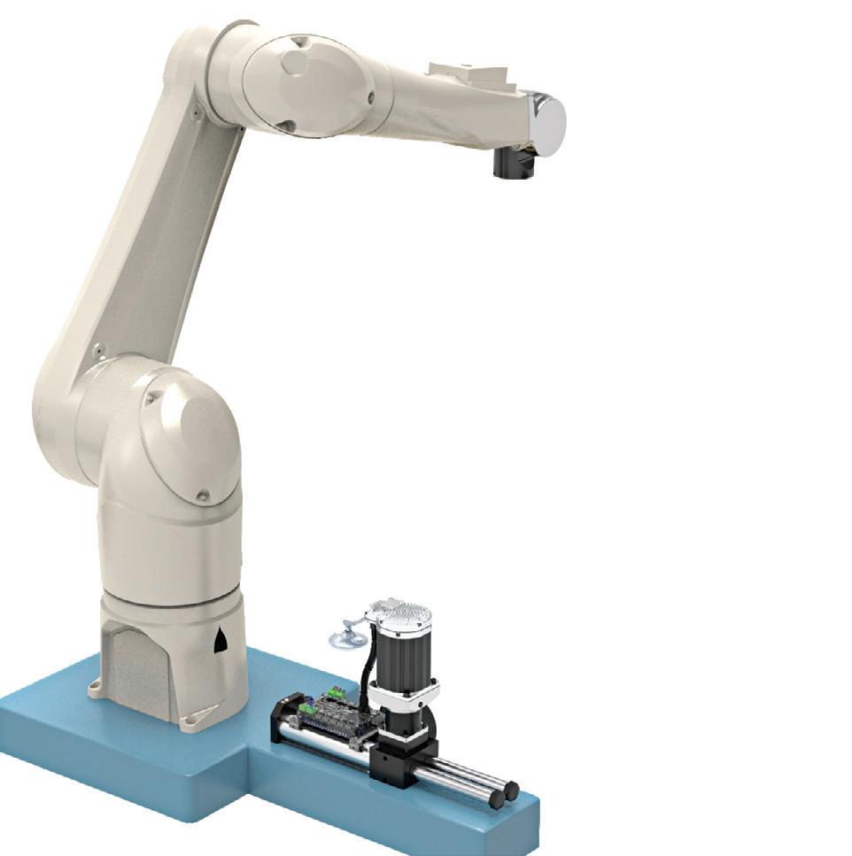
ELECTRIC VEHICLE DESIGN CONSIDERATIONS


Built-in Option Module Slot


For custom stand-alone PLC I/O con gurations that exactly match your application (option module sold separately).
CLICK PLUS PLCs provide the same simple, practical control the CLICK PLC line is known for but with some surprising bells and whistles. Data logging, Wi-Fi connect-ability, MQTT communication, and increased security measures are just a few of the impressive features offered with the CLICK PLUS PLC series.
Using the same FREE streamlined PLC programming software as its predecessor, CLICK PLUS PLCs provide straightforward, no-learning-curve programming. Combine that with a starting at price of just $97.00 and the CLICK PLUS PLC is undoubtedly the unmatched value leader!


Use any CPU with option module(s) as a complete PLC for small systems or expand the I/O with stackable I/O modules for larger applications.


Mary C. Gannon • Editor-in-Chief
Is AI ready to take on engineering?
A FEW WEEKS AGO, my youngest daughter had a fever for a week so my older girls turned to Google to learn more. They panicked, as Google’s AI summary said a 104° F fever is cause to rush to the ER. But I knew better, so showed them dozens of legitimate medical sites, all stating the exact opposite.
This got me thinking — just how much should we be using AI in our jobs? Not only is it inaccurate at times, it consumes more energy than most users realize. According to the World Economic Forum, Microsoft said its CO2 emissions had risen nearly 30% since 2020 due to data center expansion. Similarly, Google’s GHG emissions in 2023 were almost 50% higher than in 2019, largely due to the energy demand tied to data centers.
I dug deeper to learn how manufacturers
are using it. One friend uses AI to research for his customer base. His team found that AI often has small but important technical and mathematical errors, so it’s critical to go back and check its work. He added that sometimes, a number might be off by a decimal point, or its source information may be inaccurate. He compared it thus, “Some days you can have graduate assistant level work, and then other days it’s more in line with a summer intern with good grades and a resume who landed their first real summer job.”
I also learned from a colleague how the company Monumo is redesigning electric motors with deep tech engineering. Its machine learning-friendly Anser Engine can now run 10 million simulations in 24 hours and identify the optimal parameters for spe-
cific motor use-cases to reduce cost, increase efficiency or improve sustainability.
These are both good examples of how we can use this constantly evolving technology to better our systems, machines and components. Here, AI is assisting engineers and technical personnel to design the machines of the future and benefit manufacturing.
Considering energy use, it’s wise for manufacturers who use AI to do extensive research to find the most beneficial uses. Like my story, Google search was already doing a better job of answering questions accurately. Perhaps it’s time to put that type of AI behind us and focus our energies on truly better engineering. FPW
Mary C. Gannon • Editor-in-Chief mgannon@wtwhmedia.com linkedin.com/in/marygannonramsak


FEBRUARY 2025
FEATURES
26
MOBILE HYDRAULICS
System considerations in electric vehicle design
Understanding design considerations of traction, work functions, braking and more helps users optimize electrified vehicle design.
34
INDUSTRIAL HYDRAULICS
Hydraulic systems’ critical role in automotive stamping presses
Modern hydraulic systems are transforming metal forming processes, delivering unmatched precision, energy efficiency, and cost-effectiveness.
38 PNEUMATICS
Which air compressor capacity control mode is best?
Understanding the five control modes helps users find the most efficient setting on their industrial air compressor.
43 BAUMA SHOW PREVIEW
Gearing up for bauma 2025
Billed as the largest trade fair for the construction industry in the world, bauma returns to Munich April 7-13.


PRINT PRODUCTION
VP, Creative Services Matthew Claney mclaney@wtwhmedia.com @wtwh_designer
Art Director Erica Naftolowitz enaftolowitz@wtwhmedia.com
@dw_marygannon
Director, Audience Growth Rick Ellis rellis@wtwhmedia.com
Audience Growth Manager Angela Tanner atanner@wtwhmedia.com
PRODUCTION SERVICES
Customer Service Manager Stephanie Hulett
shulett@wtwhmedia.com
Customer Service
Representative
Tracy Powers
tpowers@wtwhmedia.com
Customer Service Representative
JoAnn Martin
jmartin@wtwhmedia.com
Customer Service Representative
Renee Massey-Linston renee@wtwhmedia.com


Customer Service Representative
Trinidy Longgood tlonggood@wtwhmedia.com www.nfpa.com


FLUID POWER WORLD does not pass judgment on subjects of controversy nor enter into dispute with or between any individuals or organizations. FLUID POWER WORLD is also an independent forum for the expression of opinions relevant to industry issues. Letters to the editor and by-lined articles express the views of the author and not necessarily of the publisher or the publication. Every effort is made to provide accurate information; however, publisher assumes no responsibility for accuracy of submitted advertising and editorial information. Non-commissioned articles and news releases cannot be acknowledged. Unsolicited materials cannot be returned nor will this organization assume responsibility for their care.
MARKETING
VP, Operations
Virginia Goulding vgoulding@wtwhmedia.com @wtwh_virginia
Digital Marketing Manager Taylor Meade tmeade@wtwhmedia.com @wtwh_taylor
SALES
Ryan Ashdown 216-316-6691 rashdown@wtwhmedia.com
Jami Brownlee 224.760.1055 jbrownlee@wtwhmedia.com
Mary Ann Cooke 781.710.4659 mcooke@wtwhmedia.com
Jim Powers 312.925.7793 jpowers@wtwhmedia.com @jpowers_media
Courtney Nagle 440.523.1685 cseel@wtwhmedia.com @wtwh_CSeel
LEADERSHIP
CEO, Co-Founder Scott McCafferty smccafferty@wtwhmedia.com @SMMcCafferty


FLUID POWER WORLD does not endorse any products, programs or services of advertisers or editorial contributors. Copyright© 2025 by WTWH Media, LLC. No part of this publication may be reproduced in any form or by any means, electronic or mechanical, or by recording, or by any information storage or retrieval system, without written permission from the publisher. SUBSCRIPTION
SUBSCRIBER

Mary C. Gannon • Editor-in-Chief
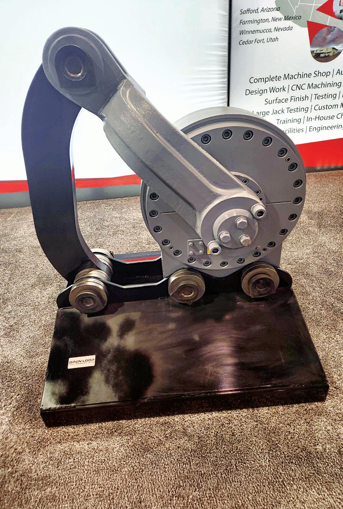
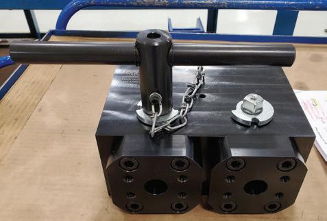
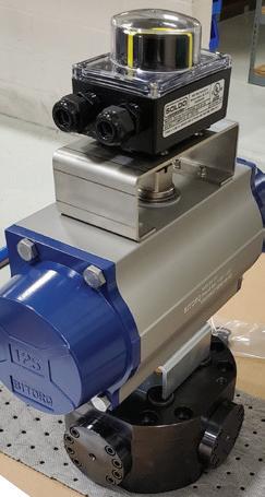
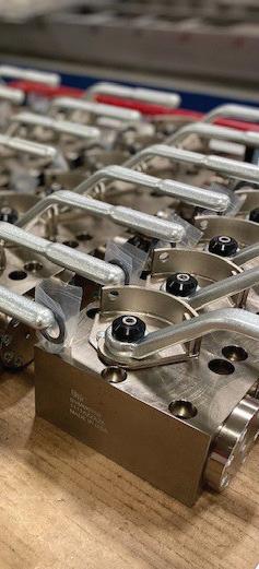
Linear hydraulic snubber ensures controlled movements on mining shovel bucket doors
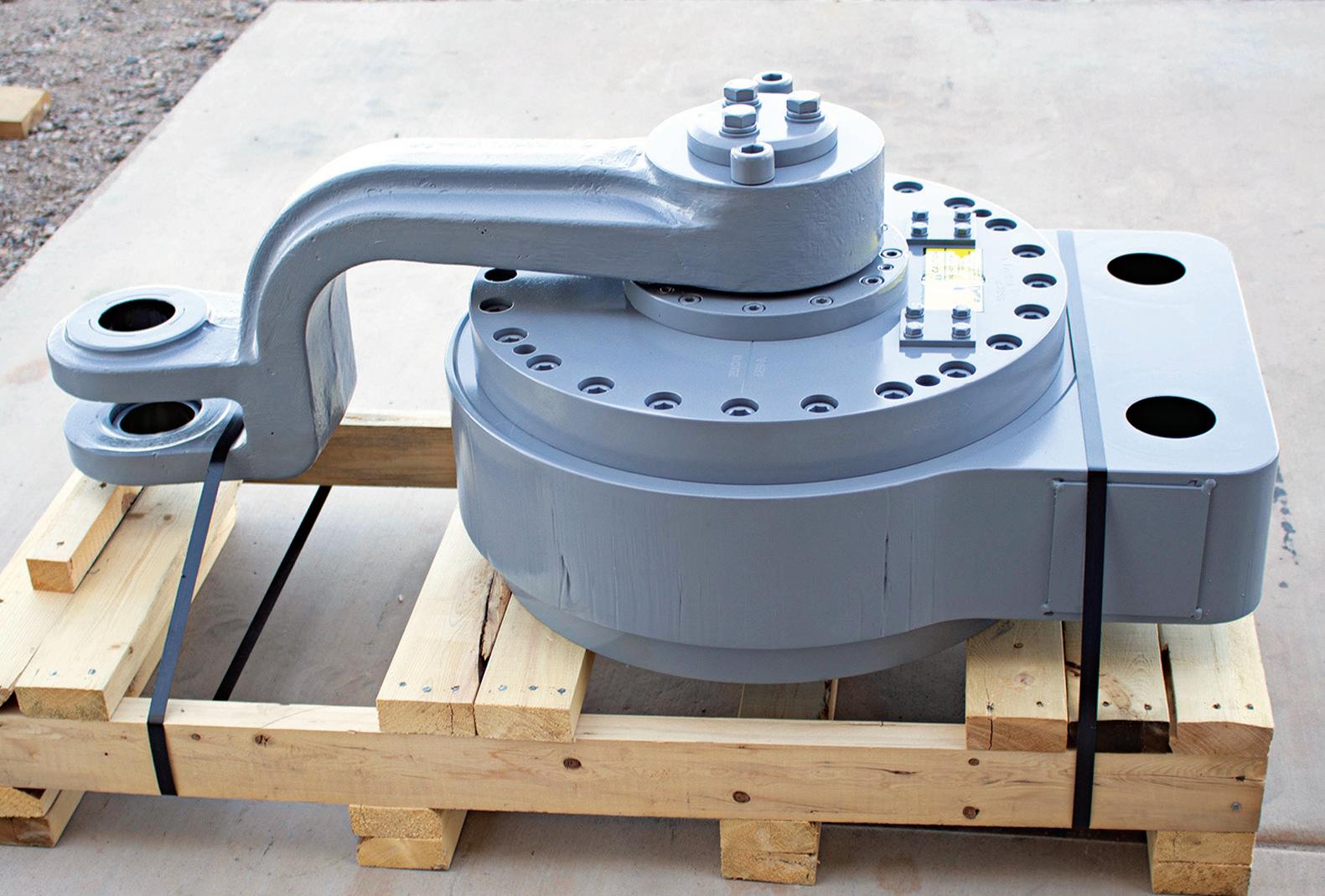
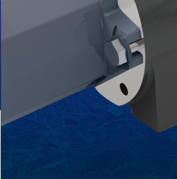
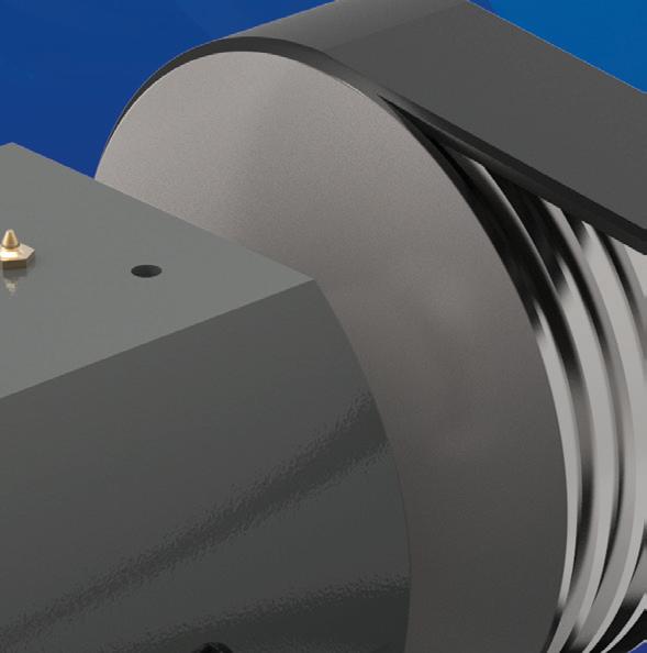
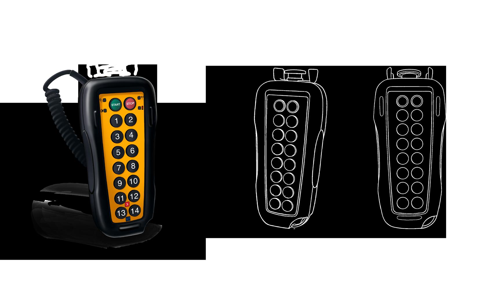
OPEN LOOP ENERGY INC. was founded more than 30 years ago as a hydraulic repair business for mining and construction machinery in the Southwest United States. But the company soon saw a need to manufacture a very specific component used on the bucket doors of the massive shovels used in these applications. Critical yet often overlooked, the hydraulic snubber contributes to the reliable operation of the shovel doors. They act as a dampening device, controlling the movement and impact forces of the shovel door (also referred to as the dipper door) as it swings open and smoothly closes during the loading and dumping process. Without a properly functioning snubber, these doors, weighing up to 30,000 lb, can slam shut uncontrollably, causing severe structural damage and premature wear.
During the dumping phase, snubbers slow the swing of the dipper door as it opens, preventing it from slamming violently. Similarly,
during reclosing, the snubber ensures the door settles back into place smoothly without shock loading the dipper structure.
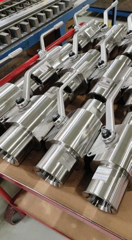
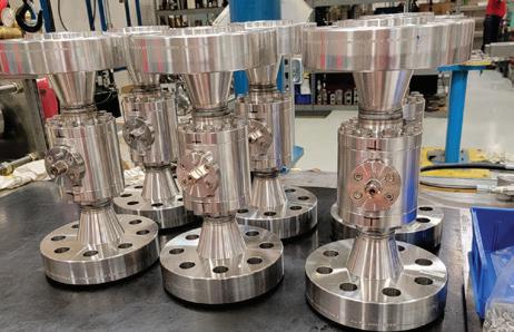
While most dual-acting bucket door snubbers are manufactured directly by OEMs themselves, Open Loop Energy manufactures the HydroSnub, which offers longer life and control, said Dow White, Director of Business Development. Because the internal components, the housing, and in particular, advanced sealing, are manufactured in house, Open Loop has better control over the snubber’s efficiency, he said.
Open Loop’s advanced seals minimize bypass leakage, increasing efficiency and reliability. The closed system does not require an external fluid supply or pressurization, making it truly maintenance-free from the end-user perspective.
The HydroSnub reduces maintenance costs and boosts operator confidence. They do not require periodic servicing, lubrication, or
Hydraulic snubbers have proven themselves as a critical component that delivers clear operational benefits.
adjustment. Maintenance needs are primarily limited to inspecting connecting pins. “It never requires maintenance,” Waite said. “The only maintenance is you have to keep the pin tight. If the pin comes out, you can have some serious damage.”
The HydroSnub controls and dampens the door's swing, particularly when it opens to dump material into haul trucks and closes in preparation for the next load cycle. By controlling the momentum of the door, snubbers prevent uncontrolled motion that could otherwise lead to:
• Excessive structural wear on the dipper and connecting arms
• Damage to pin connections and latching mechanisms
• Time-consuming and costly repair or replacement of components
A hydraulic snubber consists of a rotary hydraulic actuator filled with oil and fitted with specially designed valves and orifices, said Waite. The snubber is attached between the dipper door and the shovel itself through a connecting arm or banana arm, he said. During operation, the arm swings with the motion of the door. The weight of the door movement creates pressure by compressing hydraulic oil in the actuator.
The oil passes through a series of precisely machined orifices, creating a controlled flow path that resists sudden motion. This controlled resistance slows the swing of the door, preventing uncontrolled impacts while ensur-


HYDRAULIC SNUBBERS ARE USED TO CONTROL THE OPENING AND CLOSING OF THE DIPPER DOORS ON MINING BUCKET SHOVELS.


We understand that industrial needs can come in many shapes and forms. Our diverse line of hydraulic components are designed to fit any need you may have. When it comes to reliability, no other product on the market compares to what Yuken Hydraulics has to offer!
Our commitment to quality assurance will give you the confidence that your machinery is running safely and efficiently every time. So don’t settle for anything less.
ing smooth operation.
“As the door swings open, this arm now causes the compressed oil to move to the other side. The little orifices with the advanced seal ing are designed to bypass,” Waite said. “It oper ates like airplane overhead bin doors. When you try to close your overhead bin, it kind of slows it. It’s the same principle as a shock absorber but it is rotary rather than a linear cylinder.”
HydroSnubs are designed as direct replace ment parts, offering compatibility across vari ous OEM dipper configurations, including mod els from Komatsu and Caterpillar, said Waite. There are no complex modifications needed during retrofitting, reducing installation time and complexity.
Hydraulic snubbers are often seen as an improvement over traditional mechanical or disc-style snubbing systems. Some manufactur ers still use friction-type disc snubbing systems which face considerable maintenance chal lenges, said Waite. Snubbers also minimize oil leakage, reducing wear over time. This results
in a significantly longer service life, often spanning years under normal operating conditions. Without a functioning snubber, uncontrolled door slams lead to extensive damage over time, requiring hundreds of hours for rebuilds. They prevent deformation and cracking, ensure longevity for pins, locks and other latching components, and reduce misalignment and other structural issues.
By minimizing these impacts, hydraulic snubbers eliminate an estimated 100 to 200 hours of rebuild time for each door failure, Waite said.
Whether viewed as a retrofit upgrade or as part of a new design specification, hydraulic snubbers have proven themselves as a critical component that delivers clear operational benefits. For engineers, recognizing and specifying hydraulic snubbers can directly contribute to stronger, more efficient, and more reliable mining operations. FPW
Open Loop Energy openloop.net


WE
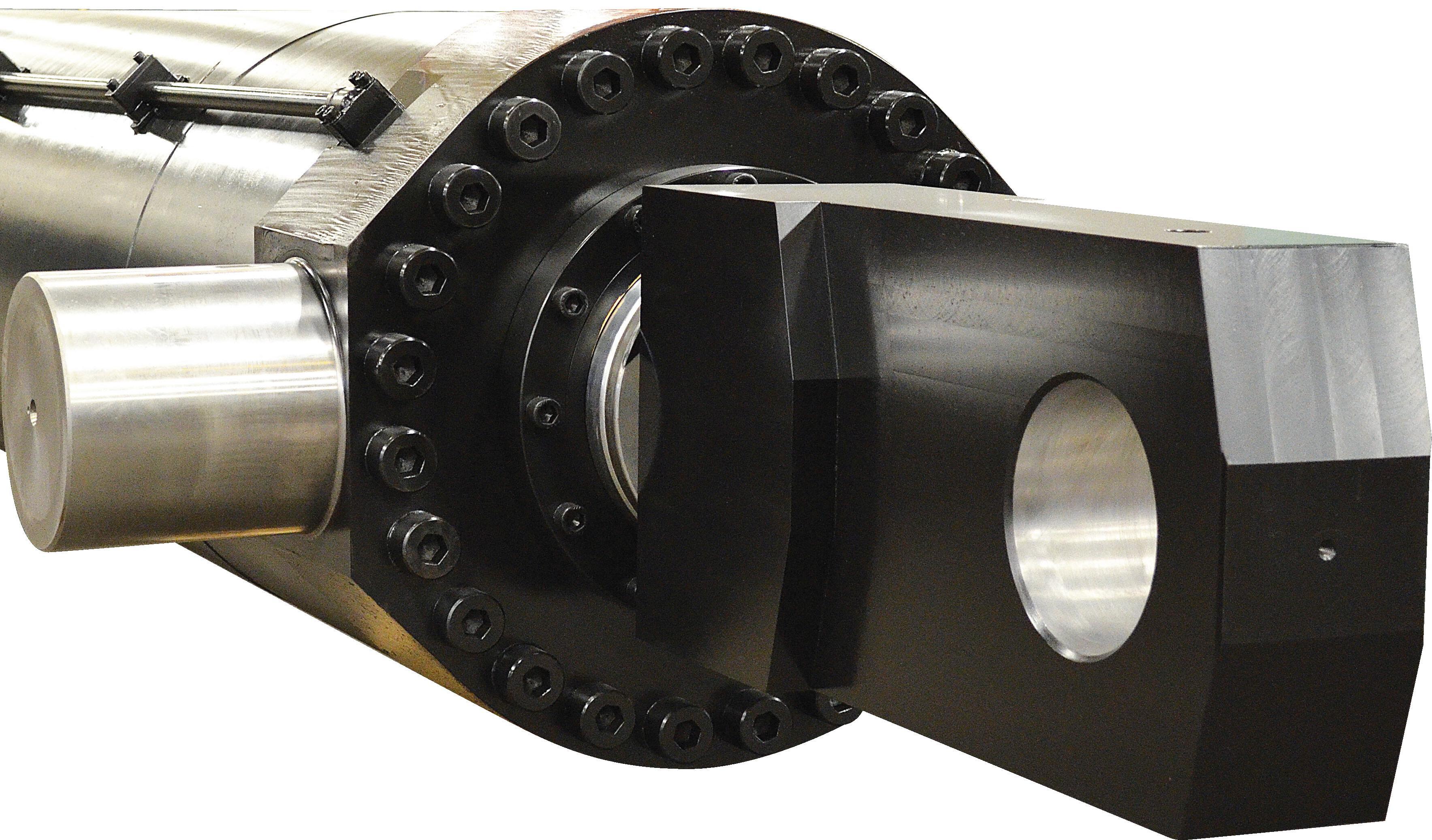
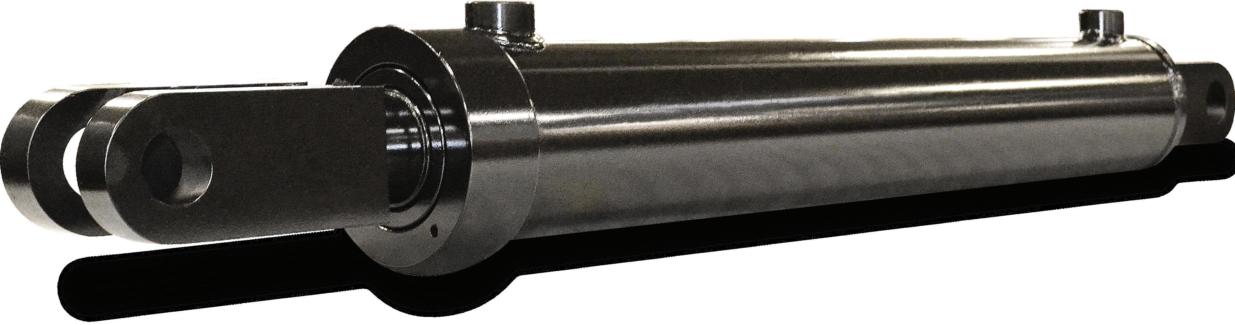
OPEN LOOP ENERGY MANUFACTURES THE HYDROSNUB, A RETROFIT HYDRAULIC SNUBBER USED TO CONTROL OPENING AND CLOSING OF DIPPER DOORS ON LARGE BUCKET SHOVELS.

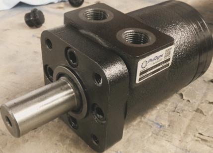
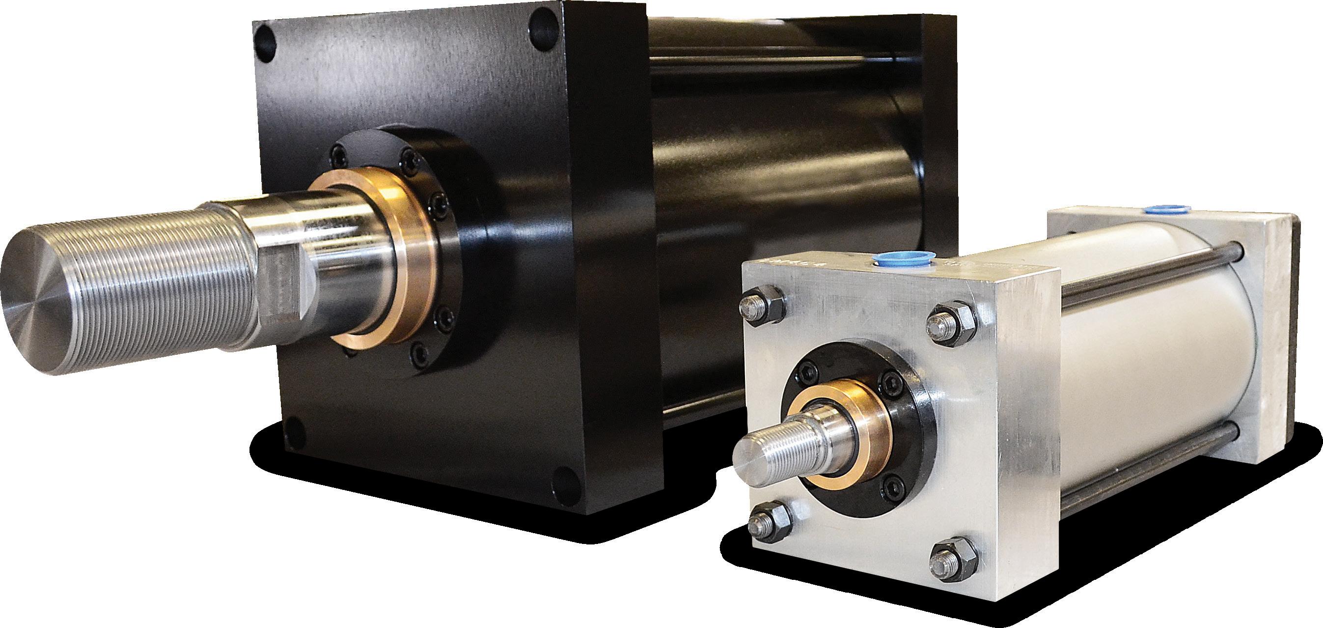
Exhausted actuators can finally breathe
THE PHD ERDP REMOTE DRIVE IS A CLOSED-LOOP SYSTEM THAT CAPTURES COMPRESSED AIR ENERGY INSTEAD OF EXHAUSTING AND WASTING IT.
vation, technology, and commercialization lead at PHD. “After compressed air is introduced into the cylinder to move the piston, the volume behind that piston still contains energy. If we exhaust the air on the next cycle to move the piston in the opposite direction, all that energy is removed from the system.”
monitoring. However, pneumatic systems are also designed for frequent intentional air releases as part of regular operation, which exhausts usable energy and wastes money.
“A pneumatic actuator is pretty much a set of air tanks on either side of a movable piston within a cylinder,” said Matt Williams, the inno-
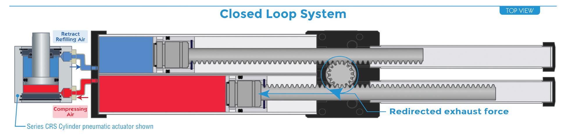
Though pneumatic actuators typically have higher power density, actuate faster, and produce more force than electrically driven counterparts, energy losses result in sunk costs and increase the system’s carbon footprint. To solve the problem, Williams’ team developed the PHD ERDP Remote Drive as an electrified option and point-of-use alternative. The ERDP forms a closed system to recycle energy in the exhaust air. It comprises two opposing cylinders with pistons, each connected to one actuator port. When the remote drive cycles, it compresses air on one side and expands it on the other without exhausting any air.
“If you think about an actuator, we inject compressed air on one side of the piston, and on the other side, we exhaust. Now, tradition-
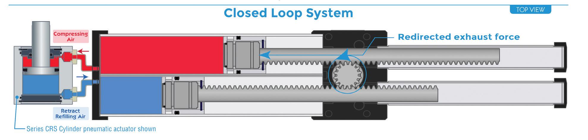
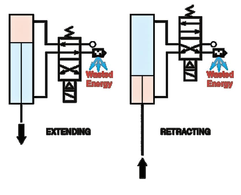
INTENTIONALLY EXHAUSTED COMPRESSED AIR.
ally, we exhaust back to the ambient environment, and then we lose all the energy from the previous cycle’s compressed air,” said Williams. “Instead, we bring the compressed air into the exhaust side of the remote drive and extract that energy. The pressure it has provides a force that acts against a piston, and that force is transferred over to the side doing the air compression. If you want to reverse the direction of the actuator, we just reverse the direction of the remote drive.”
The remote drive uses atmospheric air and seals when it begins to operate. However, it automatically “takes a breath” if it ever needs more air.
“At the end of each cycle, for a brief period, we breach the piston and open the cavity to ambient air,” said Williams. “If we’ve lost any air on the prior cycle, a partial vacuum forms when we return the piston back to its original position. And that partial vacuum, if it exists, if the leak has occurred, pulls in whatever quantity of air from the atmosphere it needs to replace the amount of air lost. If there’s no lost air, if you have a well-sealed system, the system remains completely closed, and we never add any air. But if you leak a little air, we add only a little air to compensate. If you leak a lot of air, we add a lot of air to compensate. And that’s all done automatically by the physics within the system.”
PHD offers a standard ERDP 54 unit that is


Rachael Pasini • Senior Editor


customizable based on the application’s actuators, displacement, and desired pressure. The assembly consists of the drive, controller, motor power supply, and regeneration clamp. Machine builders add their own power supply, PLC cables, air lines, fittings, and actuators. Though the ERDP has one set of actuator ports, machine builders can drive multiple actuators in parallel so that they move in the same direction simultaneously. Alternatively, they can add valves between the remote drive and multiple actuators to drive them sequentially.
“We’ve targeted the range of actuators predominantly used for end-of-arm tooling applications, but we can scale that technology and make bigger or smaller units,” said Williams. “For instance, we’re working on a very large unit for a major automotive manufacturer that is driving a robot about the size of a piece of Earth-moving equipment and driving multiple actuators at the end of about a 20-ft robotic arm. In this case, the unit becomes big and is about 75 lb worth of weight. So, we can tai-
lor the technology for the load.”
THE ERDP REMOTE DRIVE FREES UP SPACE ON THE ROBOTIC ARM AND SAVES PAYLOAD CAPACITY BECAUSE IT IS INSTALLED REMOTELY FROM THE END EFFECTOR.
The technology can also be used in industrial and medical applications, food processing, and nearly any picking operation that uses pneumatic actuation. Mobile robots are just one of many candidates that can benefit.
“Typically, the only piece of pneumatic equipment on mobile robots is the end effector, and they need that for force and speed. So, they’re stuck having an air compressor on the unit solely to drive that particular actuator. Everything else is electrified already,” said Williams. “If we can replace that air compressor with the
remote drive and gain some energy efficiency, we can obviate their need for compressed air.”
Williams also noted that when comparing pneumatic and electric actuators, electric ones are typically heavy and have their mechanisms exposed, whereas pneumatic actuators save significant capacity in size and weight.
“If you think about an end-of-arm application, if I add more weight to the end effector, I’m subtracting that weight from the payload capacity of the robot,” he said. “So, we take the motor, which is the heaviest part of the whole system, both for the remote drive, but also for a typical fully electrified actuator, we offboard that, remove it from the actuator, and we place it somewhere not on the end of the robot arm.”
Overall, the remote drive is positioned to save energy, costs, and carbon footprint while creating more flexible design options for engineers and machine builders. FPW
PHD phdinc.com


Helical spline actuators enable safe, easy lifting
MARQUIPT IS A MARINE and yachting equipment manufacturer specializing in products that facilitate easy and safe boarding of persons and the handling of tenders. Its product line comprises stairs, ladders, gangways, davits, cranes, and other equipment.
“We support a wide range of customers from individual boat owners … to OEM boat builders,” said Lee Byrd, MarQuipt’s vice president. Finding an optimal boarding solution for each boat and the persons using it requires addressing various details as well as determining the needs of the people involved. Some boats, for example, are not universally accessible or designed for easily getting people on and off the boat. Some individuals can easily step across the gap between the boat and dock, while others require more assistance and security to help get them across. Other times, there is a large height difference to accommodate as well as the gap. As such, MarQuipt approaches each case as a unique situation.
“When people come to us with their boarding needs, the first questions we ask concern who’s getting on and off, how much help do they need, and if there are any pets involved,” mentioned Byrd.
Some cases may involve the installation of an articulating staircase where handrails and no gaps between the dock and boat are imperative details. In other situations, a vertical ladder that can be easily stowed away or some alternate arrangement may be a better solution.
“We encounter many different boarding situations in accommodating people who require various degrees of assistance,” said Byrd.
Hydraulic rotary actuators safely power davits and cranes
In addition to boarding equipment, MarQuipt also manufactures a range of davits and cranes which are essential for safely lifting and maneuvering tender boats onto yachts and other vessels. Similar to the challenge of providing appropriate boarding equipment, lifting equipment must also be carefully specified to meet the needs of each vessel.
Rachael Pasini Senior Editor
“It is much more secure to be able to push a button and have the davit rotate under power even if the tender only weighs 800 lb or 1,000 lb,” Byrd said.
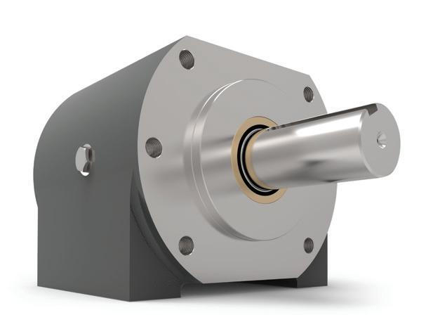
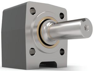
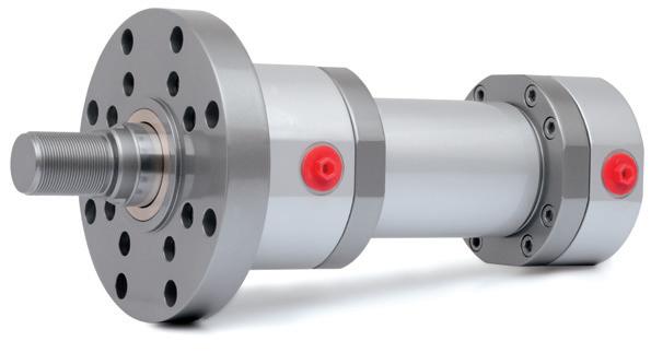
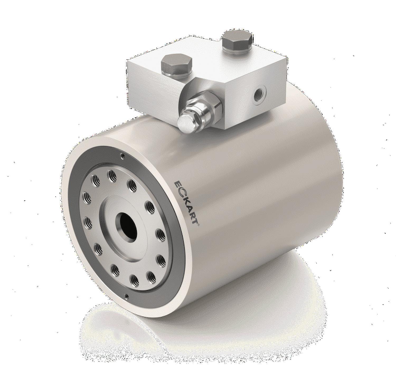
Eckart E3 hydraulic rotary actuators save space
In some smaller davits, tenders are lifted with a boom and manually rotated with a tagline, while higher capacity davits and cranes are fully powered hydraulically. This involves a hydraulic boom and a hydraulic rotary actuator installed in the base of the machine. The boom and cable lift the tender, while the actuator rotates the boom and tender 180° or 360° to easily move the tender and bring it aboard.
While full hydraulic rotation has traditionally been a feature reserved for higher capacity davits and cranes, MarQuipt has found it beneficial to also offer powered rotation in smaller davits to provide improved safety and convenience. For example, some tenders are stowed in locations where safe handling becomes more challenging. A davit mounted on an upper aft deck can be dangerous to manually rotate, as the user must manually push and pull the tender to rotate it into position. It becomes more challenging when the upper deck lacks safety railings.

For these and other reasons, offering powered rotation provides for a safer alternative to manually rotating the davit and tender, even when the tender is relatively small and lightweight.
MarQuipt’s solution was to add Eckart’s hydraulic rotary actuators into the system due to their compact, helical spline design.
“They’re compact and self-contained, so we can more easily fit them inside of our equipment,” Byrd explained.
Eckart’s rotary actuators contain their own rotation stops, which means the device did not have to be specially engineered to fit MarQuipt’s equipment. They are also easily replaceable if needed.
“They’re easy to swap out if we’ve got a problem. We’ve designed our davits to make removal for repair or replacement easier than with some other actuators,” said Byrd.
Marquipt designed some of its davit models, such as the MarQ series and TenderLift 2, around the small size of the Eckart E3 hydraulic rotary actuator.
Over time, some customers have seen the advantage of upgrading their davits to fully powered operation. Previously, this required MarQuipt to provide various models that differed substantially both visually and in design and construction.
MarQuipt saw an opportunity to optimize their designs and eliminate unnecessary components by integrating the Eckart E3 hydraulic rotary actuators into their davits. The actua-
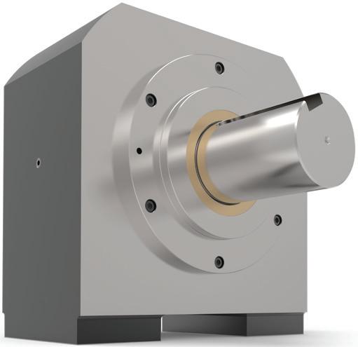
ECKART E3 HYDRAULIC ROTARY ACTUATOR.


tors fit into the same enclosure housing components in non-powered rotation versions of the same davit. As a result, MarQuipt was able to simplify the provision of powered rotation to smaller davits and lower the overall cost for the customer.
“Because we could fit the rotary actuator inside our existing housing, we could reduce some costs and make that option to power rotary things more attractive,” Byrd said.
Behind Eckart’s E3 hydraulic rotary actuator
The Eckart E3 is specially constructed for mobile applications and can provide 180° or 360° of
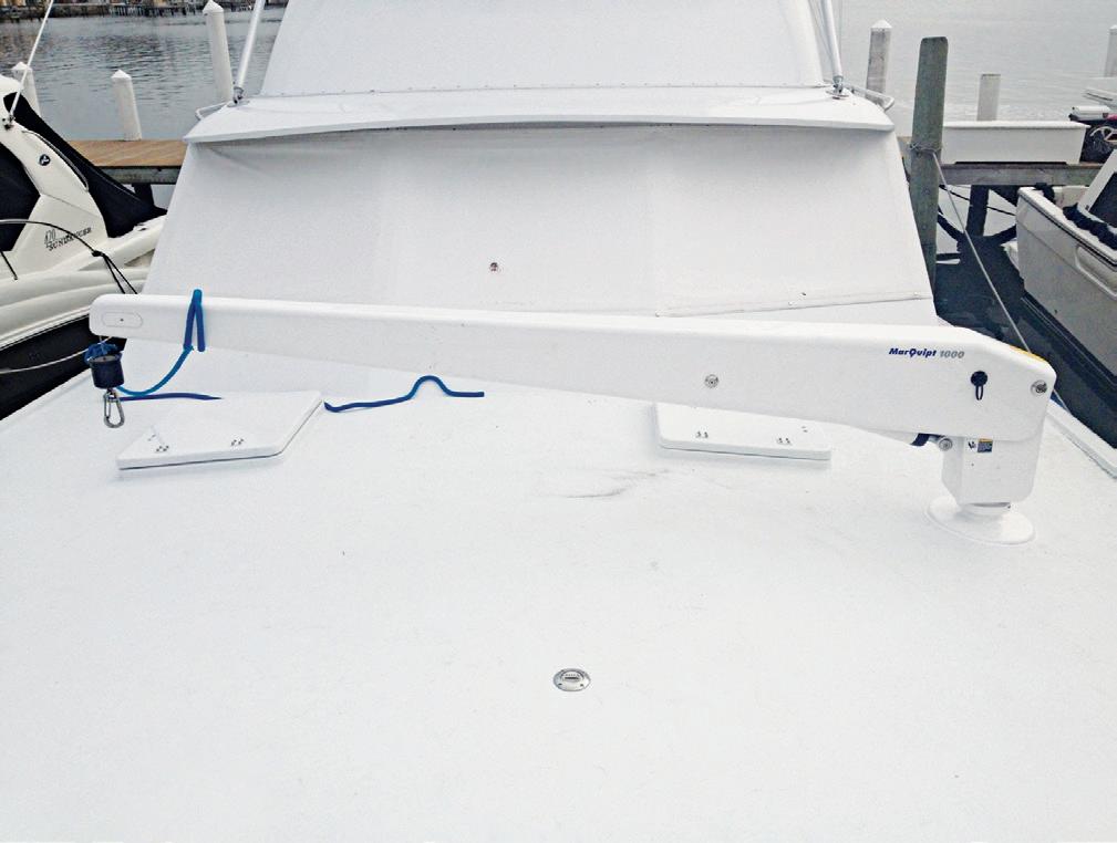
THE LEFT IMAGE SHOWS THE MARQ 8 TENDERLIFT ROTATION DAVIT WITH AN 800-LB LIFTING CAPACITY. THE MIDDLE AND RIGHT IMAGES SHOW THE MARQ 10 TENDERLIFT ROTATION DAVIT WITH A 1,000-LB LIFTING CAPACITY.
rotation with up to 210 bar (3,045 psi) or more. Its four-point bearing is designed to handle side loads and multi-directional forces. This is particularly useful in applications subjected to high forces and continuous movement.

president of IC-Fluid Power.
Like all Eckart actuators, the E3 uses the helical spline and gear principle for compactness.
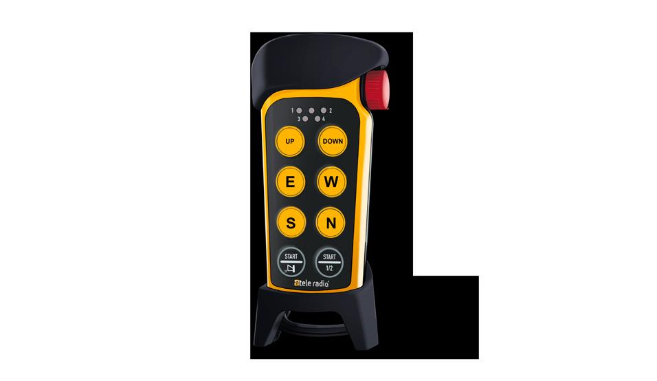
Fluid Power World - Tele Radio US - Half page January.pdf 3 17/12/2024 11:51:41
“Oftentimes, applications seem simple, but when you think about the application, such as ones experienced by davits and cranes in their natural environment, where saltwater environments are coupled with the motion of the boat, the forces acting on components can change suddenly. Eckart actuators excel in demanding environments due to their integrated fourpoint bearings and internal corrosion protection, amongst other things,” said Ben Hunger,
The unique design also ensures a steady and low-wiggle working platform, as the threads and ball bearings have minimal backlash, and no bi-directional seals are used.
Eckart E3 rotary actuators have been used across several MarQuipt series of davits, such as the TenderLift Classic, TenderLift 2, MarQ 8, MarQ 10, MarQ 15, MarQ 17 davits, and larger TenderLift cranes, providing lifting capacities from 800 lb up to thousands of pounds. FPW IC-Fluid Power icfluid.com


Visit one of four US locations:
Yates Cylinders, Inc.
Corporate O ce
23050 Industrial Dr. E. St. Clair Shores, MI 48080
Phone: 586.778.7680
sales@yatesind.com
Yates Cylinders Ohio 550 Bellbrook Ave. Xenia, OH 45385
Phone: 513.217.6777
ohsales@yatesind.com
Yates Cylinders Alabama
55 Refreshment Place
Decatur, AL 35601
Phone: 256.351.8081
alsales@yatesind.com
Yates Cylinders Georgia
7750 The Blu s Austell, GA 30168
Phone: 678.355.2240
gasales@yatesind.com


May 5th-8th
Booth #1537


Josh Cosford • Contributing Editor
Understanding vacuum cup materials
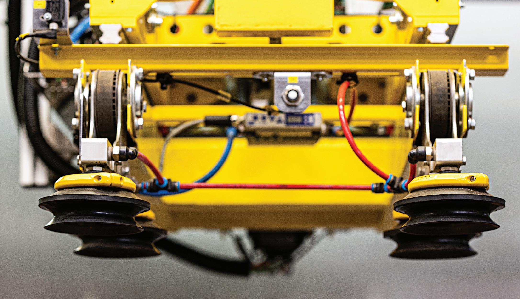
IN VARIOUS INDUSTRIES, such as automation and material handling, vacuum cups play a crucial role in securely gripping and transporting items of varying shapes, weights, and surface textures. The material composition of these cups directly influences their performance, durability, and suitability for specific applications. Manufacturers produce vacuum cups using a variety of materials to suit a variety of applications: silicone, nitrile, polyurethane, EPDM, vinyl, Viton and even natural rubber run the gambit of options.
Silicone is a highly versatile material commonly used in vacuum cups due to its excellent temperature resistance, flexibility, and ability to maintain its properties across a broad range of conditions. Silicone vacuum cups are often employed in industries where hygiene and cleanliness are critical, such as food processing, pharmaceuticals, and medical device manufacturing. Their resistance to high temperatures also makes them suitable for handling hot items, such as freshly molded plastics.
Nitrile rubber (Buna or NBR) is another popular choice for vacuum cup materials. It provides excellent oil and grease resistance, making it ideal for applications in the automotive and manufacturing sectors. NBR vacuum cups are frequently used to handle metal sheets, engine
Choosing the right vacuum cup material is essential for optimizing efficiency and reducing downtime in automation and material handling systems.
components, and oily or greasy surfaces. Their durability and wear resistance make them a cost-effective choice for high-volume operations.
Polyurethane is prized for its exceptional wear resistance and elasticity. Vacuum cups made from polyurethane are well-suited for handling abrasive materials or objects with rough surfaces. This material is commonly found in applications such as woodworking, where sharp edges and coarse textures are prevalent, and in packaging, where durability is essential for long production runs.
Although silicone, nitrile and polyurethane are very popular, manufacturers offer various other compounds that might be suitable for your particular application or environment. EPDM, for example, offers fantastic resistance to UV light, ozone, and a wide range of chemicals that could harm other materials. These
properties make it an excellent choice for outdoor applications or environments where exposure to harsh chemicals is common. EPDM vacuum cups are often used in the construction industry to handle concrete blocks, tiles, and other building materials. Additionally, their resistance to aging and weathering makes them a reliable choice for extended operation.
Vinyl vacuum cups are lightweight and offer good resistance to chemicals and water. They are frequently used in applications that involve lightduty handling of delicate items, such as electronics, glass, or fragile packaging materials. However, vinyl is less durable than other materials and is best suited for applications where low cost and light use are priorities.
Fluoroelastomers, such as Viton, are renowned for their chemical resistance and capacity to withstand extreme temperatures. This makes them ideal for applications in the chemical and aerospace industries where exposure to aggressive chemicals and high heat is common.
Natural rubber, such as latex, offers excellent elasticity and high friction, providing a strong grip on smooth or irregular surfaces. This material is commonly used in general-purpose vacuum cups for applications like carton handling, logistics, and general manufacturing. While natural rubber is not as resistant to oils or chemicals as synthetic alternatives, its affordability and performance make it a popular choice for basic tasks.
Choosing the right vacuum cup material is essential for optimizing efficiency and reducing downtime in automation and material handling systems. Factors such as temperature, surface texture, chemical exposure, and durability requirements must be carefully considered to ensure compatibility with the application. By selecting the appropriate vacuum cup material, industries and manufacturers can achieve reliable performance and extend the lifespan of their handling equipment. FPW


THE EAGLE HAS LANDED


Ron Marshall • Contributing Editor
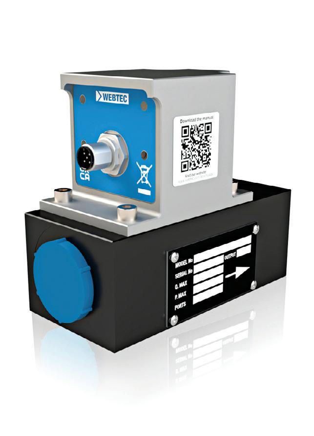
Using a portable flow meter makes sense ... and cents
“Quite often, you will find some significant leakage and perhaps compressed air system waste, such as uncontrolled blowing or cooling with compressed air.”

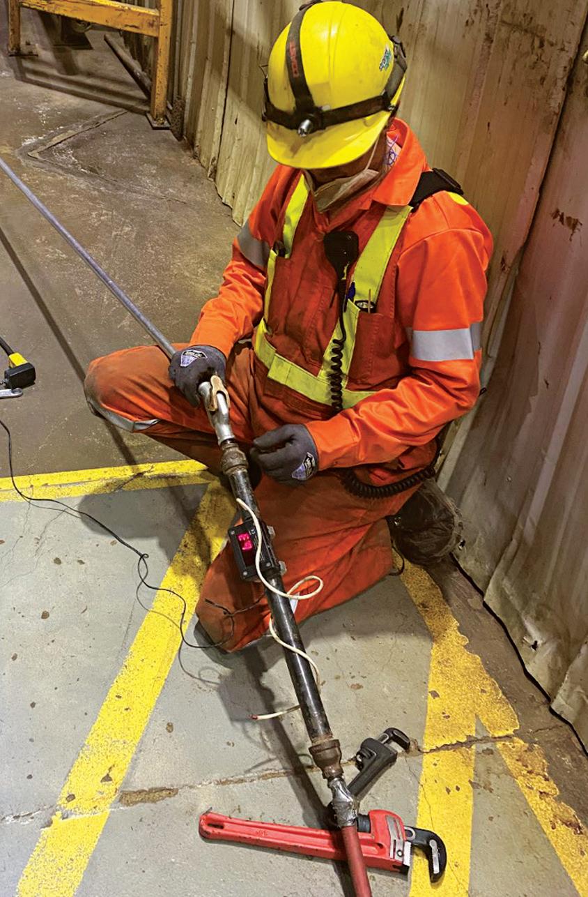
WHEN PERFORMING LEAKAGE DETECTION
on your compressed air system with your ultrasonic leak detector (if you don’t have one, good grief, run out and get one!), you will run across various leaks in piping and equipment. Many of these are small, so roughly less than $100 value per year.
But quite often, you will find some significant leakage and perhaps compressed air system waste, such as uncontrolled blowing or cooling with compressed air. When you locate a big, wasted flow, the question will be: how much com pressed air is it consuming and what is the cost?
You can compare the flow measured by a main flow meter before and after a change, in order to help you estimate leakage — but in a big plant, this is not an option. So, with a little cre ative thinking, we can come up with a very accurate, inexpensive, and portable leak measuring assembly for you to use in measuring compressed air consuming devices and leakage.
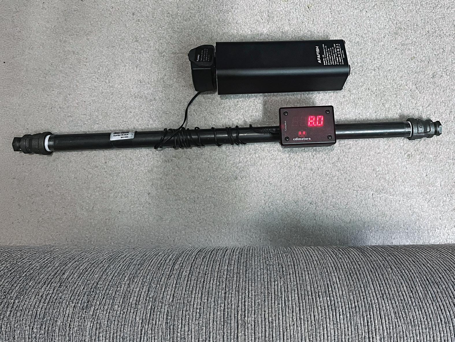
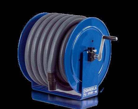
All it takes is to purchase a small insertion flow meter, a length of pipe, some fittings and as an added option, a battery power bank (example shown in Fig. 1).
The use of this measurement assembly is simple: install it in-line with the device to be tested and read the number. Then take the flow reading, multiply by about 0.2 (the number of kW per cfm in a typical system), then times the number of annual hours the device is operating. This gives you the kilowatt hours per year. Multiply this by the cost of electricity from the electrical bill and you have an estimate of annual cost.
Here is an example calculation from Fig. 2: 83 cfm x 0.2 kW per cfm x 1000 hours per year x $0.1 per kWh = $1,660 per year
Sometimes this device cannot be installed inline. If so, no problem — hook it up to any handy port and back feed the leak with an alternate source of compressed air to get the measurement.
Measure your waste, and you may be surprised by the result!
FIGURE
FIGURE 2
Devin Purcell • Technical Trainer
Fight the brain drain with apprenticeships programs

Editor’s note: In this new multi-part series, Devin Purcell will tackle the skills shortage that the fluid power industry is facing and offer creative solutions to address this challenge.
WE CANNOT FIND GOOD TECHNICIANS.
No matter what industry seminar, convention, or get together you attend these days the same subject comes up over and over. Shops have a tremendous amount of work but cannot find skilled technicians to staff their facilities. While there are many different strategies at play across the world to help fill this skills shortage, many are picking up the phone and contacting senior technicians who have already retired. Senior technicians have a lifetime of skills and experience that can only be gained with time. Senior technicians have skills to share and improve the younger generation’s skillset. Sounds like a great idea on the surface. After all, having a senior technician who can hit the ground running after some orientation and safety training is worth their weight in gold. The most important question you need to ask
BRINGING SENIOR TECHNICIANS OUT OF RETIREMENT TO TRAIN NEW APPRENTICES IS ONE WAY TO PASS SKILLS FROM ONE GENERATION TO THE NEXT.
the shop make sure they are not overworked. It is important that they have their own work to do to make sure they are still fulfilled by the job. But if you give them so much work that they do not have the time to help junior technicians when they need assistance, you’ll fail. Perhaps you can give senior technicians repair orders that are not on a time crunch, or work with customers to rebuild cylinders for extra inventory.
Document, document, document. Have regular meetings with both the senior and junior technician at regular intervals. Discuss any ideas that they have that may improve the process or what they have done that did not work well. This will help you create some standard processes that will assist you the next time you do this type of training.
yourself, though, is what are you going to do when they retire for real next time?
You are going to have the same exact problems that you have today.
What can we do to ensure that we are maximizing the value of bringing senior technicians out of retirement? Make sure that we transfer their knowledge to the next generation. This may make you rethink which senior technicians that you would like to bring back into the field. There are a few things that can be done to ensure you get the greatest value from this relationship.
Establish a clear goal. When you begin discussing with one of your retired technicians to come back to the shop, be clear and up-front about the process and what you are trying to accomplish. Passing down skills to the next generation is not a task that every person is up to, because fixing things is a different skill set than teaching skills. Make sure you identify a senior technician who you may have already noticed training younger technicians or who really enjoys taking a new apprentice under their wings.
When the senior technician comes back to
Have a set end date. This puts urgency in the hands of the trainer and the trainee. It also gives an end goal for the technician that you are bringing out of retirement. This may greatly assist you in recruiting someone to come back to work for a short period. With a set job and time to complete it, they can see the end and know they need to impart that knowledge efficiently.
While many areas of the world have a set apprenticeship program that assists in this transfer of knowledge, many do not. Make sure that you ensure the transfer of knowledge from generation to generation — this is the greatest aspect of training technicians. It is our job to take the knowledge we have learned over the years in our fields and pass it onto the next generation. Combine this with a drive to continuously learn, and the next generation will be more knowledgeable than the last. That should be our main goal — preparing them for success in their working career and helping all our shops succeed and thrive. FPW
Devin Purcell is a repair professional with more than 20 years of industry experience. As a freelance writer and technical trainer with an OEM forestry manufacturer, these skills are used to enhance the performance of learners. Contact him at devinj.purcell@gmail.com.


System Considerations in Electric Vehicle Design
By Jay Schultz, Business Development Manager, Tom Hickey, Systems Application Engineer, Electrification Growth Team, Parker Hannifin


CHANGING FROM TRADITIONAL POWERTRAINS TO ELECTRIFIED MACHINES REQUIRES OPTIMIZING THE HYDRAULIC SYSTEM COMPONENTS TO REDUCE ENERGY CONSUMPTION AND EXTEND VEHICLE RANGE.
Understanding design considerations of traction, work functions, braking and more helps users optimize electrified vehicle design.
AS MOBILE VEHICLE MANUFACTURERS begin to develop electrified versions of their product offering, they ultimately face one critical challenge: balancing range with battery costs. This article focuses on the design considerations of the systems that use the battery’s stored energy to run the key vehicle functions and how they can be optimized to reduce total energy consumption and extend vehicle range.
Key vehicle functions and system architectures
Traction – A common trait that all mobile vehicles today share is that they’re mobile and designed to be self-propelled. But besides the fact that they can all move, the actual systems behind this function can differ greatly between markets and vehicle technologies. The most common architecture is an engine-driven transmission, but it’s also worth considering traction systems that use closed-loop hydraulic systems, which consist of one (or two) over-
center variable displacement pumps driving a hydraulic motor and drive axle. In either case, the traction function is greatly impacted when re-designing for a battery electric system… specifically because, now that we have a battery, we have an opportunity to benefit from regenerative braking.
To understand regenerative braking, it’s worth mentioning how most vehicles brake today — with the vehicle at speed and the operator commanding a braking event. For example, a disc brake will clamp down on the rotating wheel and apply a friction force that absorbs the vehicle’s remaining kinetic energy in the form of heat. The important takeaway here is that the vehicle’s kinetic energy is now spent. And if the operator wants the vehicle to speed back up, more energy will be required to do so.
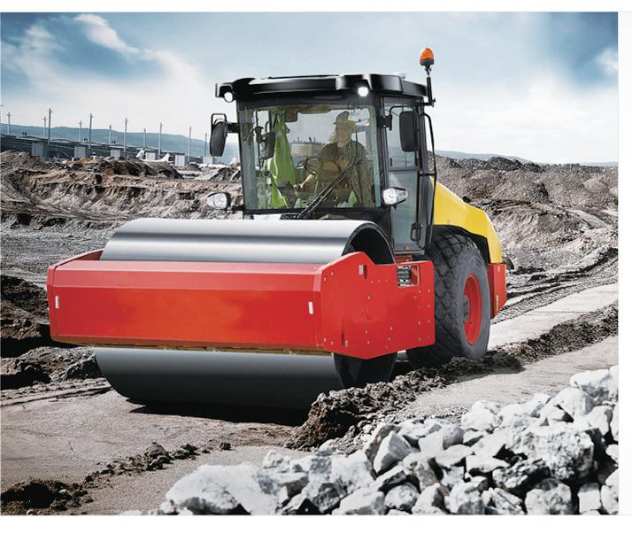
referring to vehicles that are designed to do additional functions beyond just moving from A to B. “Work” is the term we use to define these functions, and it comes in many shapes and forms. A garbage truck lifting a can or a wheel loader driving a pile are examples of work. While these vehicles are doing very different things, they are just two among many types of vehicles that leverage hydraulic systems to achieve these additional functions.
The types of hydraulic systems are diverse, but the general concept includes one or more hydraulic pumps delivering flow to a valve, which then determines how much of that flow is going to one or more demanded functions. Downstream from the valve the hydraulic flow reaches the actuator, which ultimately converts
the traditional ICE-driven hydraulic system typically expects a pump running at a fixed speed, which can be incredibly wasteful when little or no work is being demanded. And again, the key challenge in mobile electrification is balancing range with battery costs, so we are now incredibly picky about eliminating wasted energy.
To address this, we should leverage the ability to dynamically control the pump’s speed. Unlike an engine, an electric motor is designed to be commanded to a dynamic speed or torque value, with peak torque performance available at speeds as low as 0 rpm. This flexible performance at a very high efficiency is unmatched and brings the opportunity for additional optimizations in the vehicle’s hydraulic system design.
It would take another article to dive into
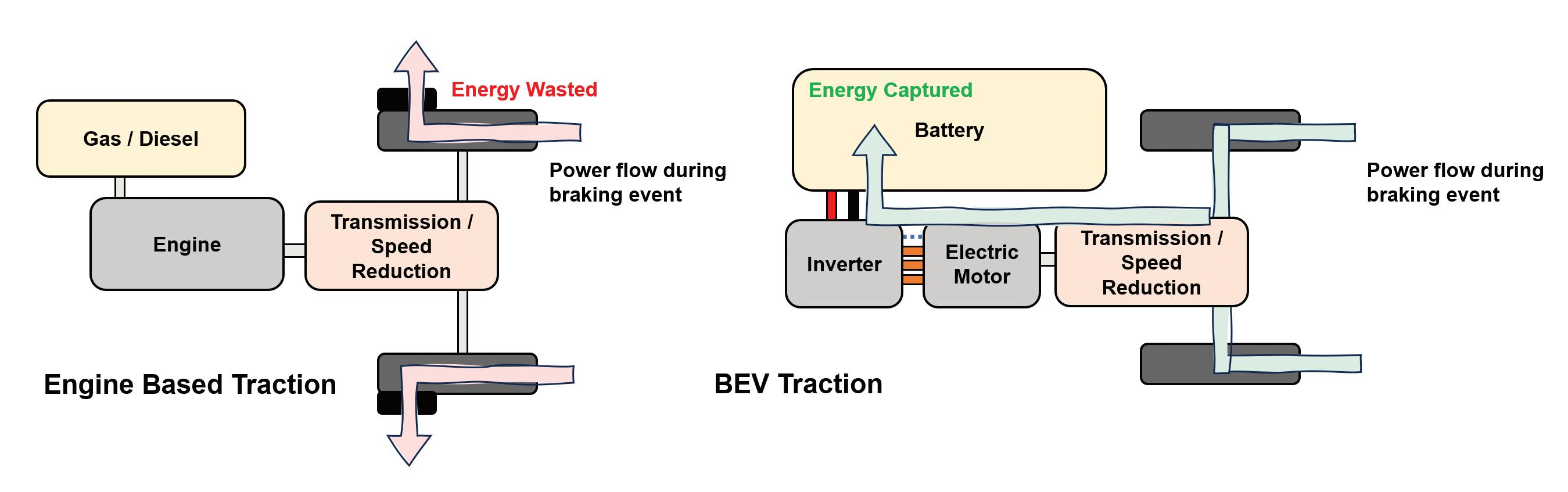
Now let’s consider traction in a battery electric system, which mainly consists of a battery (capable of bi-directional power flow when not fully charged), an inverter (which is usually capable of bi-directional power flow), and a motor (which is also capable of bi-directional power flow). With bi-directional power flow, we can now use the electric motor to apply a resistive torque to the moving vehicle, which slows it down. But as this is happening, the vehicle’s kinetic energy is converted into electrical energy and stored back into the battery. If the operator wants to speed back up, the energy just captured while braking can be used, thus significantly reducing the total energy consumption for a given duty cycle. Work – In this article, we’re mostly
this hydraulic power into rotary or linear motion. Combined, these components offer a power-dense solution with the flexibility to deliver the vehicle’s power to wherever the work is being done.
With the available technologies today, it’s hard to find a more robust alternative than hydraulics, and the expectation is that most electrified vehicle designs will still consist of hydraulic system solutions to achieve at least some of the vehicle’s work.
Although hydraulics are a mature technology, it doesn’t necessarily mean these systems won’t change in an electric vehicle design. They certainly don’t have to because there’s no reason you couldn’t just run an identical ICE-driven hydraulic system at a fixed speed off an electric motor. But
the different types of hydraulic systems that could be considered in an electrified vehicle but, before we dive into that step, we must first comb through each work function and ask the following:
• What type of motion does this function demand — linear or rotary?
• What are the function flow and pressure requirements throughout a given duty cycle?
• How does the operator and/or machine command this function?
• Does this function run in parallel with other functions?
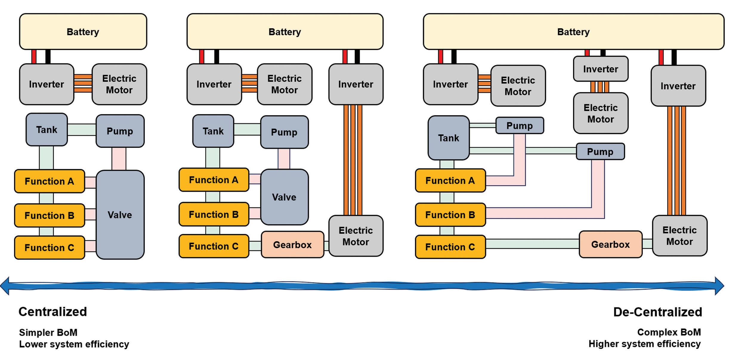
Depending on these answers, we can make a better decision on what makes sense from a design standpoint. Ultimately, the system architecture will range between ENERGY TRANSFER DURING A BRAKING EVENT, ICE VERSUS BEV COMPARISON

Motion Redefined
As the world’s first ESV, we solve motion control challenges with ingenuity. Evolution Motion Solutions combines over 80 years of industry expertise in hydraulic repair and reman services to deliver thoroughly tested, genuine factory parts. Our Bosch Rexroth factory-trained technicians restore your products to like-new condition and provide a better-than-new warranty on all repairs, ensuring your equipment operates at peak performance with minimal downtime and extended component life.
a 1-ePump centralized system to a very decentralized system consisting of many ePumps and electric motors/actuators. As the system architecture moves towards a decentralized approach, power delivery becomes more efficient. But as the design moves in this direction, the number of systems also increases which translates to higher BoM costs.
Will these costs offset the savings captured by downsizing the battery? The answer to that question will determine where exactly a vehicle design should land in the spectrum of centralized-to-decentralized systems.
cannot handle the entirety of the demanded braking energy and additional braking power may be required. Or, if the vehicle is parked on a hill, the electric motor shouldn’t be holding a brake torque at 0 speed for too long. Therefore, it is recommended to include a parking brake, which can apply the necessary holding torque to keep the vehicle stationary for an extended period.
Sizing the right components
Traction – For this exercise, we’re assuming the system architecture leverages an electric motor-driven traction rather than an electric motor driving a hydrostat (which
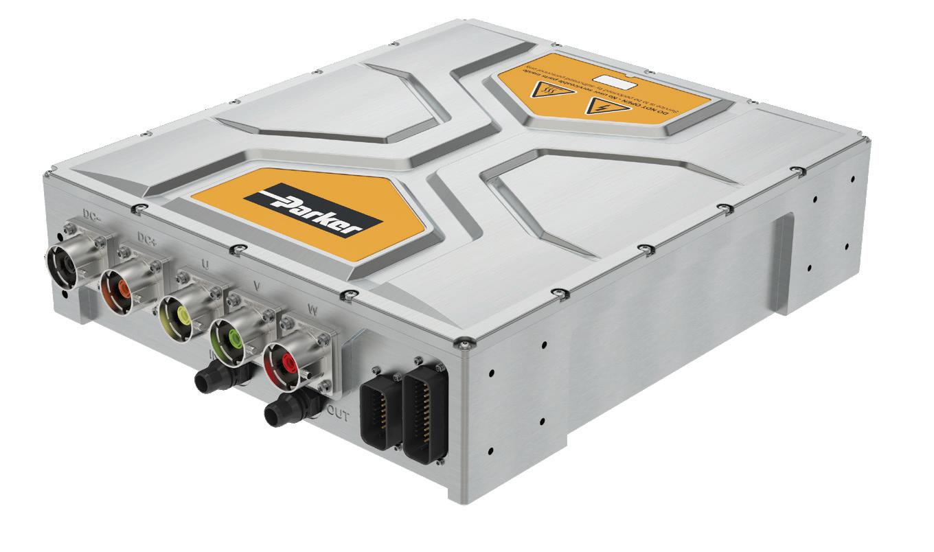
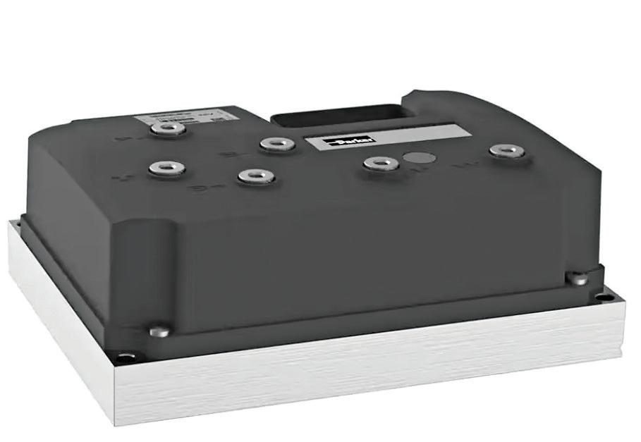
With the answers to these questions, we can select a motor and inverter combination that is designed to deliver the required torques and speeds. The Parker GVM motor series and GVI inverters, for example, bring a modular approach to meeting a diverse range of vehicle traction needs. With a variety of configurations, we can rightly size the system to meet or exceed the performance expectations of traditional mobile vehicles.
Work – The solutions to work aren’t as straight forward in electrification compared to traction and, depending on where we landed on the spectrum of centralized-todecentralized systems, we’re likely work-
Auxiliary Functions – These functions support the other two functions mentioned in this article, and the two we’ll consider are steering and brake functions. For steering, many solutions such as steer-bywire have already been developed for traditional ICE systems, and a lot of these solutions carry over well in electrified systems.
As for brake functions, are those still needed even though we’re now braking the vehicle using regenerative systems? For most cases, yes! Although much of the vehicle braking will be from the electric motor, there are cases where regenerative braking
SPECTRUM OF CENTRALIZED-TODECENTRALIZED SYSTEMS
still may exist in some electrified system architectures). But in our case, we are driving our vehicle directly with one (or two) electric motors. To size the motor, we first need to consider the following questions:
• What are the peak tractive effort requirements? How do these values translate to torque and speed?
• What speed reductions will be between the motor and the axle? Are these ratios variable?
• What different duty cycles and use cases will the vehicle’s traction system expect to see?
ing with at least one ePump. To size the motor(s) for these ePumps, we need to determine the following:
• What is the flow and pressure demand for each ePump over the course of the expected duty cycles?
• After review of the above, what is the corner condition that each ePump will see from a pressure and flow standpoint?
One quirk about electric motors and inverters is that they have two performance curves: a continuous performance curve and a peak performance curve. Selecting the right curve to abide by can be

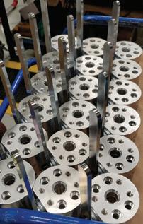
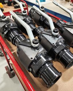
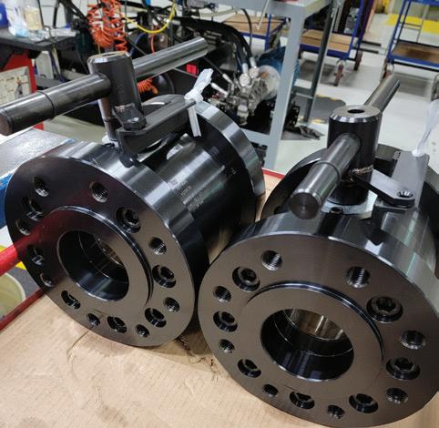
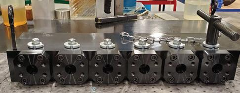
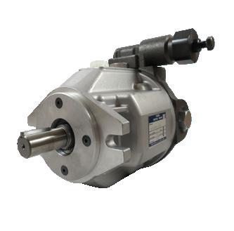
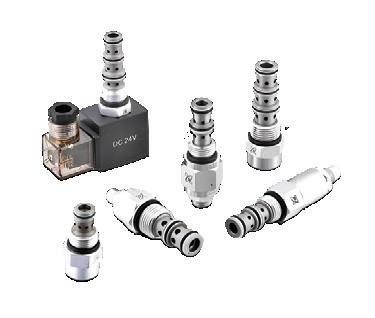
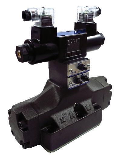
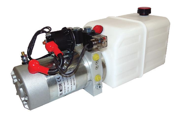
Solutions Under Pressure


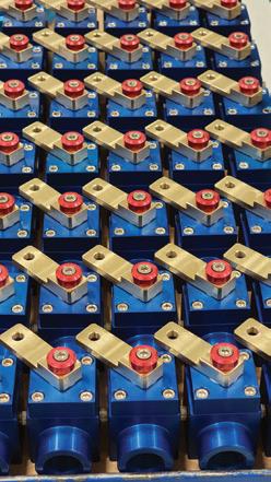
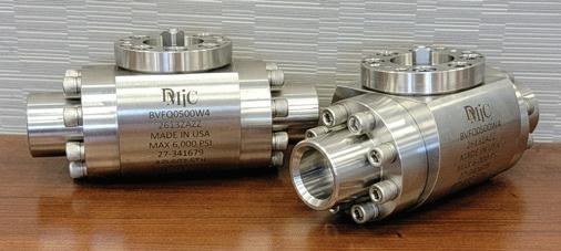
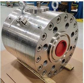
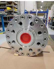
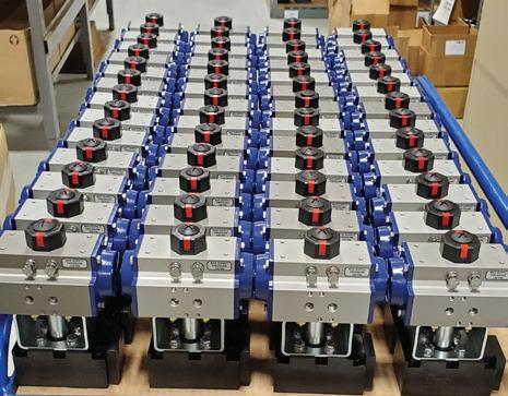
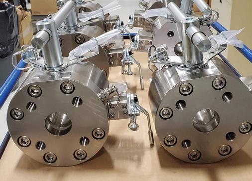
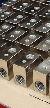
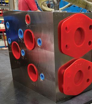
Needle
Flanges & Adapters
Bar & Custom Manifolds
Pressure Gauges & Snubbers
SSW Power Unit Systems
Transfer Pumps
Industries Served:
• Oil & Gas
• Industrial Hydraulics
• Mining
• Forestry
• Chemical & General Processing Plants
• Medical
• Aerospace
• Factories
• Mobile Equipment
• Defense
• Machine Tool
• Testing Equipment
• Ocean Depth Technology
• Automotive
• Food Processing
• Agriculture
• Industrial
•
• Petrochemical
•
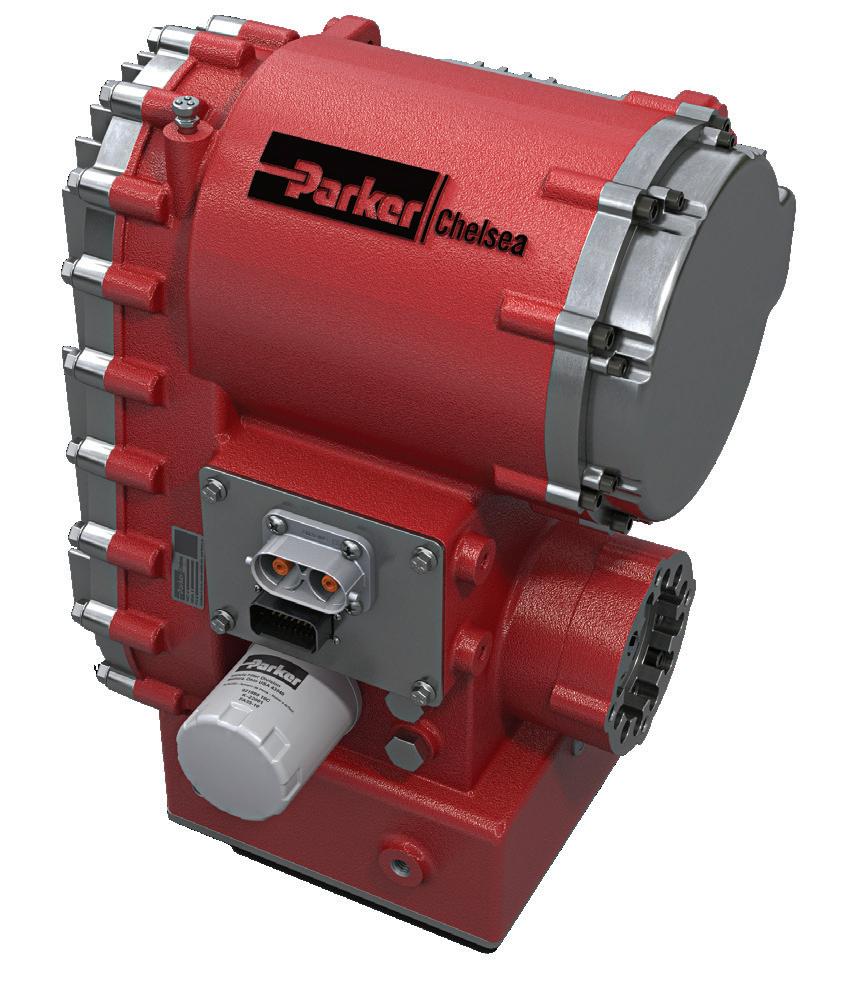
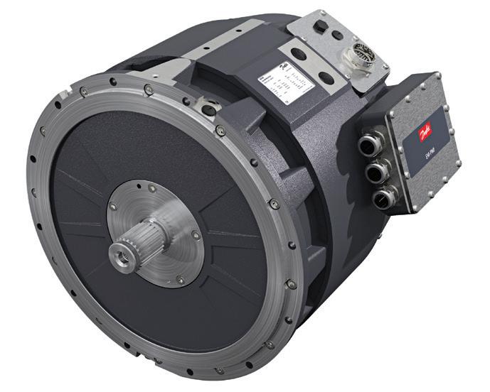
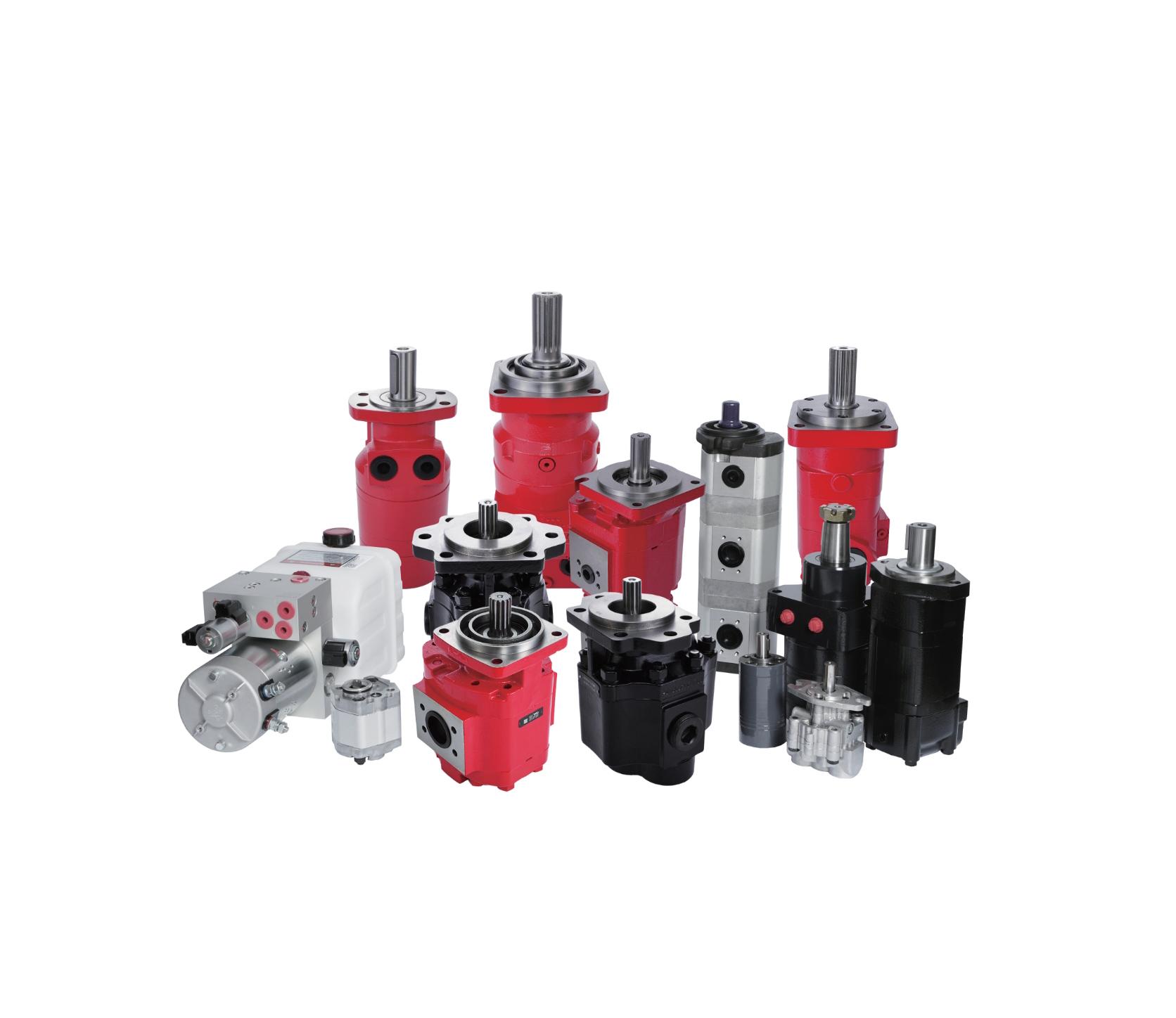
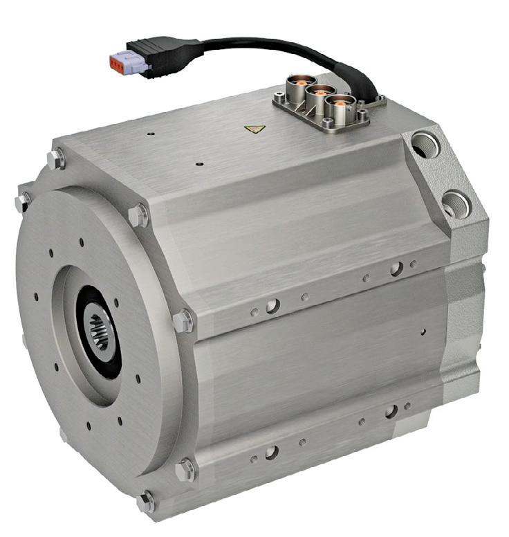
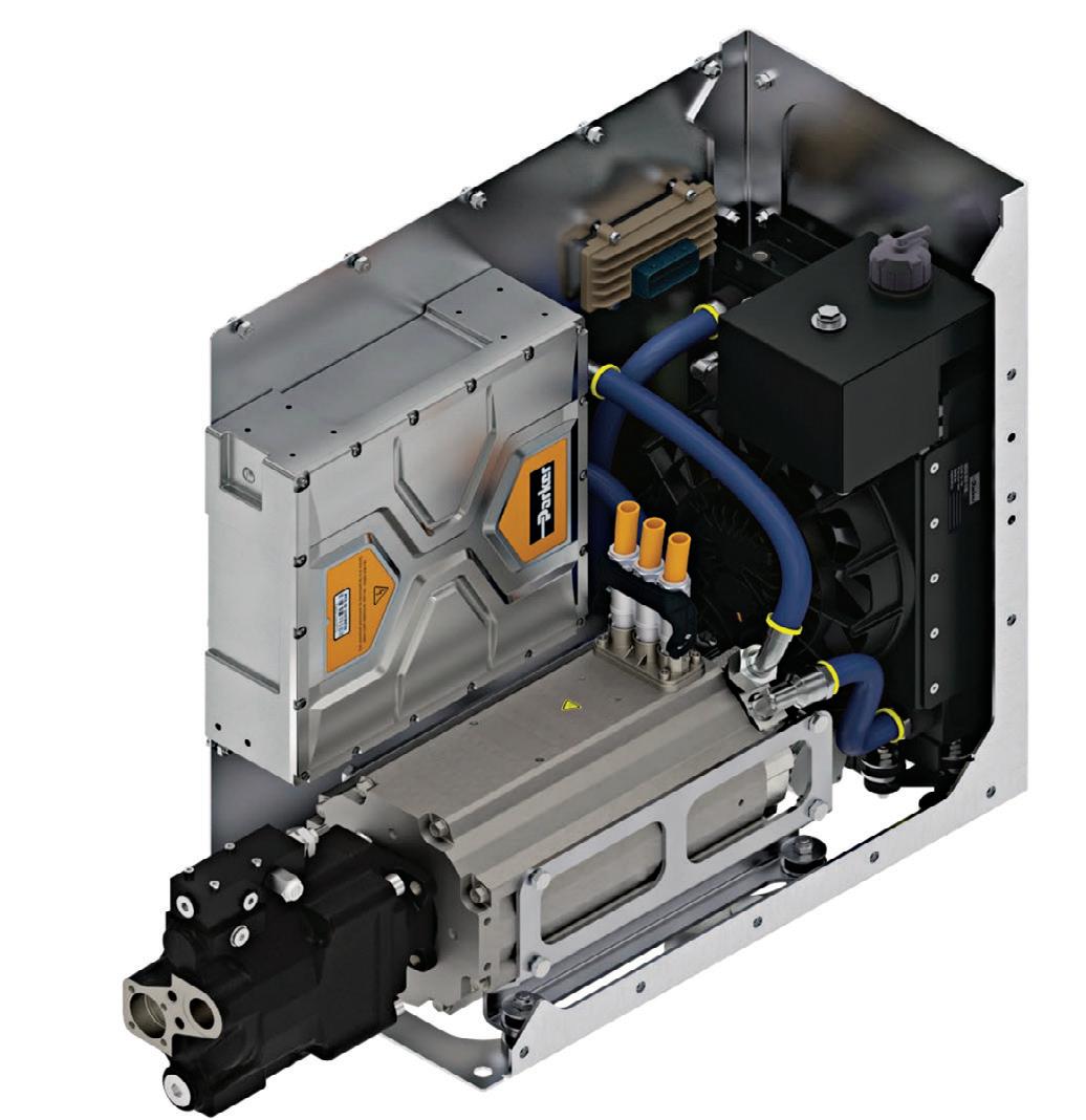
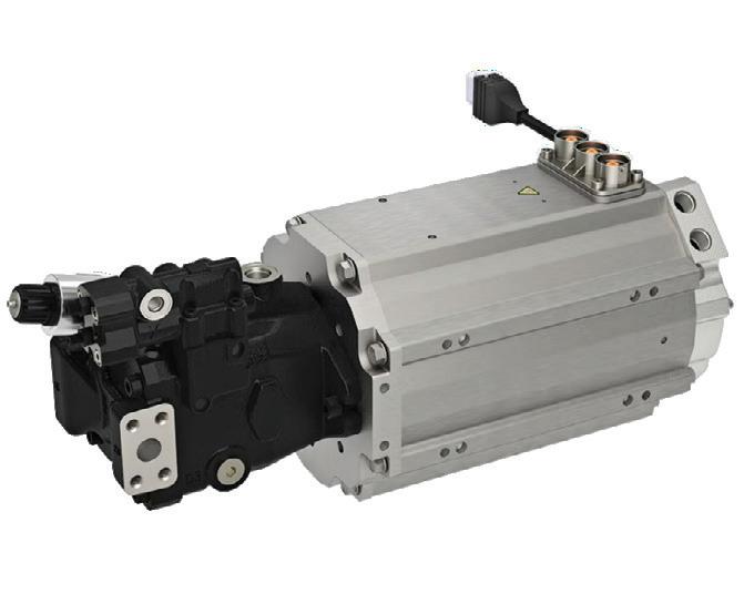
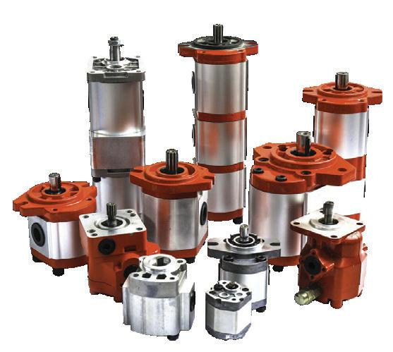
A VARIETY OF OPTIONS, SUCH AS EPUMPS, EPTOS AND MOTORS, CAN BE USED TO PROVIDE A VARIETY OF POWER LEVELS AND INTERFACES TO HELP MEET A GIVEN VEHICLE’S WORK SYSTEM REQUIREMENTS.
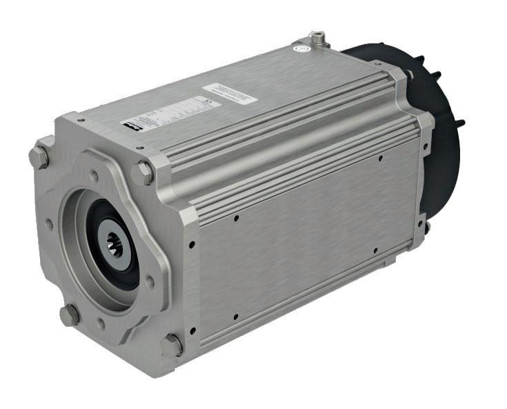
PARKER GVM MOTORS AND GVI INVERTERS BRING A MODULAR APPROACH TO MEETING A DIVERSE RANGE OF VEHICLE TRACTION NEEDS.
a bit difficult because a duty cycle is rarely just one fixed load. Therefore, the motor/ inverter requirements to do this work don’t necessarily need to be at or below the motor/inverter’s continuous performance. This is why it is beneficial to have a good understanding of the vehicle’s duty cycle, as it paints a much clearer picture of what the ePump needs to handle. With the context of demanded pressures and flows, we can select a pump displacement to deliver
these flows at a given speed and then calculate the required torque from the motor. This value, along with system voltage, ultimately enables us to select the appropriate motor and inverter.
Beyond rightly sizing the system, some of the largest efficiency gains can be captured by simply changing how the system is controlled. With the ability to vary the pump speed on the fly, the ideal scenario is that, when work isn’t being commanded,
absolutely no energy is being spent. For some functions and system architectures, this isn’t possible, as some amount of standby flow or pressure is required. But even slowing the pump to a lower standby speed can reduce energy consumption in this condition.
Additionally, hydraulic components themselves can range from very inefficient to very efficient, so any efficiency gains brought by a component change could translate into lower costs of the battery. Some work functions may benefit from being separated from the hydraulic system entirely and become electromechanically driven. This type of solution removes the inefficiencies of hydraulics entirely and enables energy recovery.
Auxiliary functions – Sizing for braking and steering systems is mostly like sizing work functions. You need to ask about the flow and pressure demands over the course of a duty cycle. The big difference to consider for these types of systems is that they are typically lighter duty than work but also are more likely to require some degree of standby flow. A case can be made to separate these systems from work systems so that the more powerful work-related components can remain off and allow the lower power components to independently switch in/out of low power standby as they’re commanded.
For both work and auxiliary functions, there are a variety of options. One path would be a component-based solution where a manufacturer can buy the hydraulic components, motors, and inverters individually. Alternatively, some companies like Parker offer packaged solutions in the form of configured ePumps and ePTOs. Either option comes in a variety of power levels and interfaces to help meet a given vehicle’s work system requirements.
When choosing a partner to assist in electrifying your vehicles, it’s important to identify a company that has a broad product portfolio and technology experts who can help guide your decision-making and support the design and integration of your next electric vehicle platform. FPW Parker Hannifin parker.com


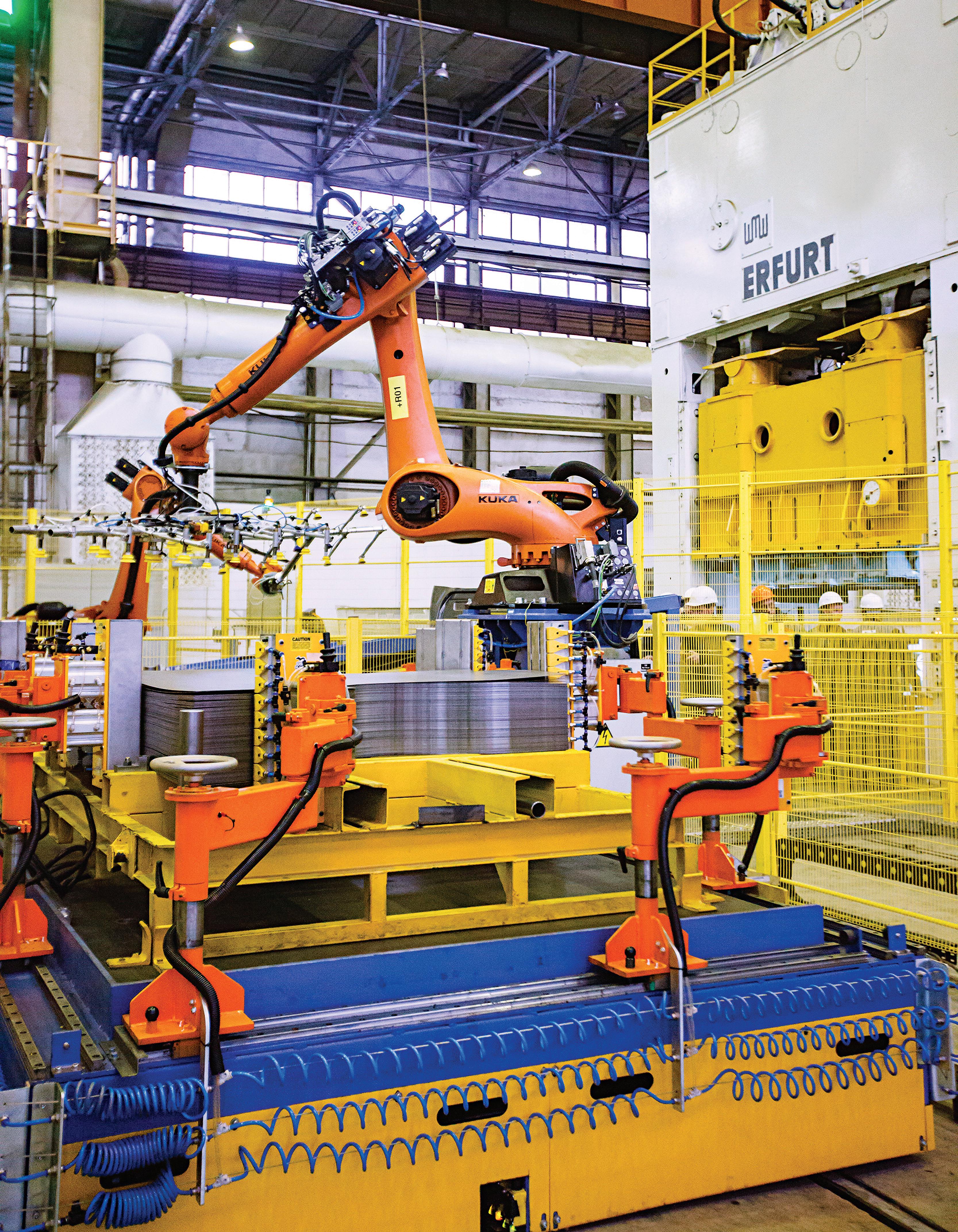
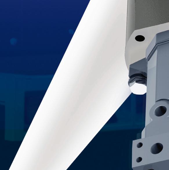
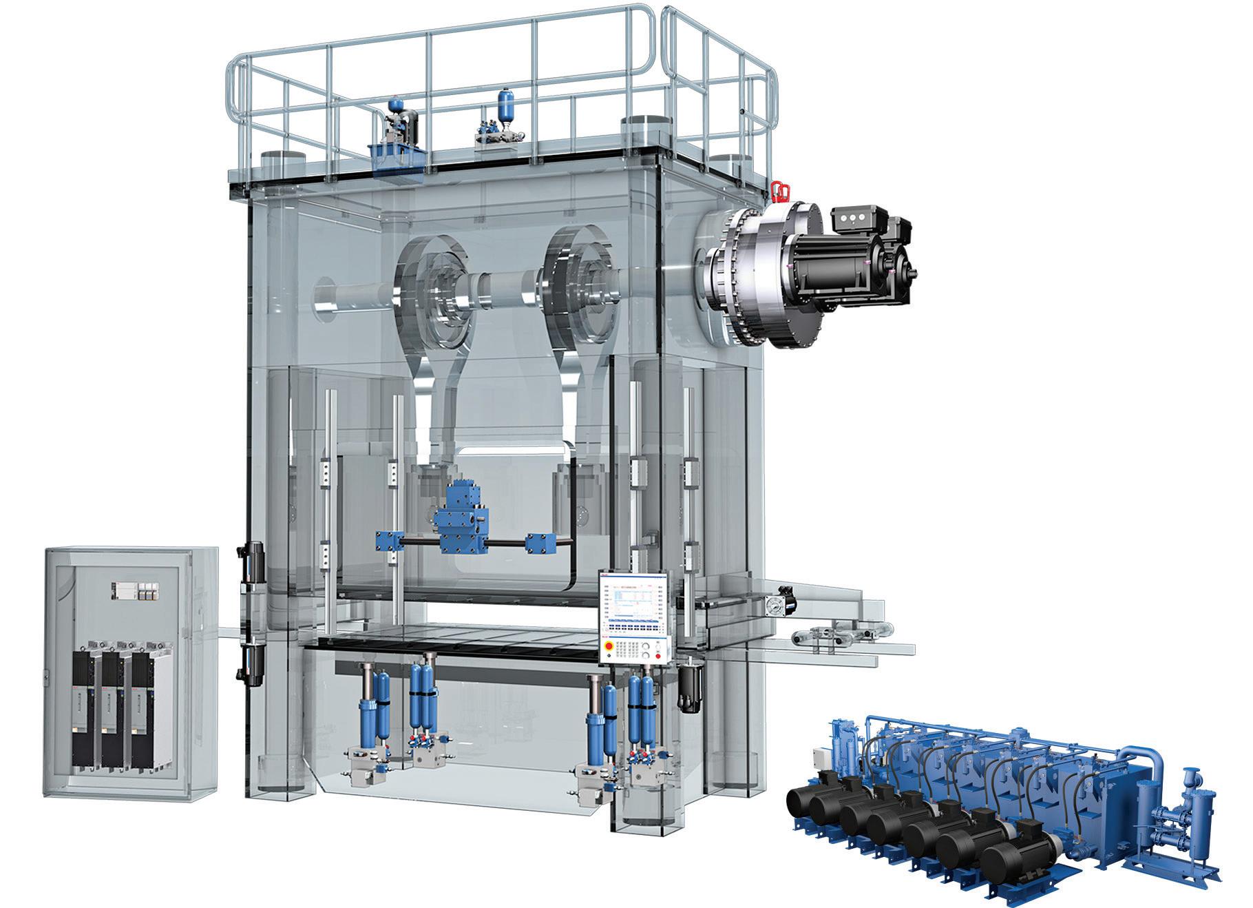
HYDRAULICS ARE USED EXTENSIVELY THROUGHOUT AUTOMOTIVE PRESS SYSTEMS, TO FORM SHAPES FOR CAR DOORS, PANELS, ROOFS, HOODS AND MORE.
Hydraulic Systems’ Critical Role in AUTOMOTIVE STAMPING PRESSES
Modern hydraulic systems are transforming metal forming processes, delivering unmatched precision, energy efficiency, and cost-effectiveness.
By: Jens Schmitt, Presses Application Manager, Bosch Rexroth
Automotive manufacturing is consistently evolving to meet market demands as new products and parts are innovated. Hydraulic systems remain a major player in creating these components with heightened precision, quality and efficiency, specifically in the metal forming stamping process. For essential car body parts like door panels, fenders, roofs, complete car side panels and hoods, the stamping process is used to form these shapes through the supporting role of a hydrau-
lic-equipped and controlled cushion system to reliably form quality parts within the lead press.
A record number of people are driving in the U.S., up 2.1% in miles traveled since pre-COVID-19 levels, and investment in the electric vehicle (ev) industry is consistently driving innovation. These factors present manufacturers with an opportunity to build efficient and dependable vehicles that not only keep manufacturing costs low but also maintain quality and safety for consumers.
INDUSTRIAL HYDRAULICS
The
metal forming process
Metal stamping automotive body parts is a process that has been streamlined by using hydraulic components for decades. To meet the rising manufacturing demands of today’s markets, hydraulic systems have continued to evolve into more precise and automated processes. The solutions used in metal forming are proving to be more dependable than ever — especially with modern software upgrades — as major car manufacturers worldwide use hydraulics systems for quality control and the prevention of body part defects. To achieve zero defects, process parameters must remain consistently equal with each stroke. The high stroke rates and large part quantities demand high pressing speeds and can only be achieved through press impact
this process, but there are still challenges inherent with implementing hydraulics in automotive manufacturing.
One complexity in this process lies in the continual, dynamic motion of the press, which requires precise force application and pressure adaptation to perfectly shape the raw material repeatedly. A valuable feature of modern systems is the force adaptation function, allowing self-learning of the cushion to guarantee accurate optimization of the cushion function — without human interference — for the complete production batch. Specifically, precise timing is also of utmost importance to not hit the material too
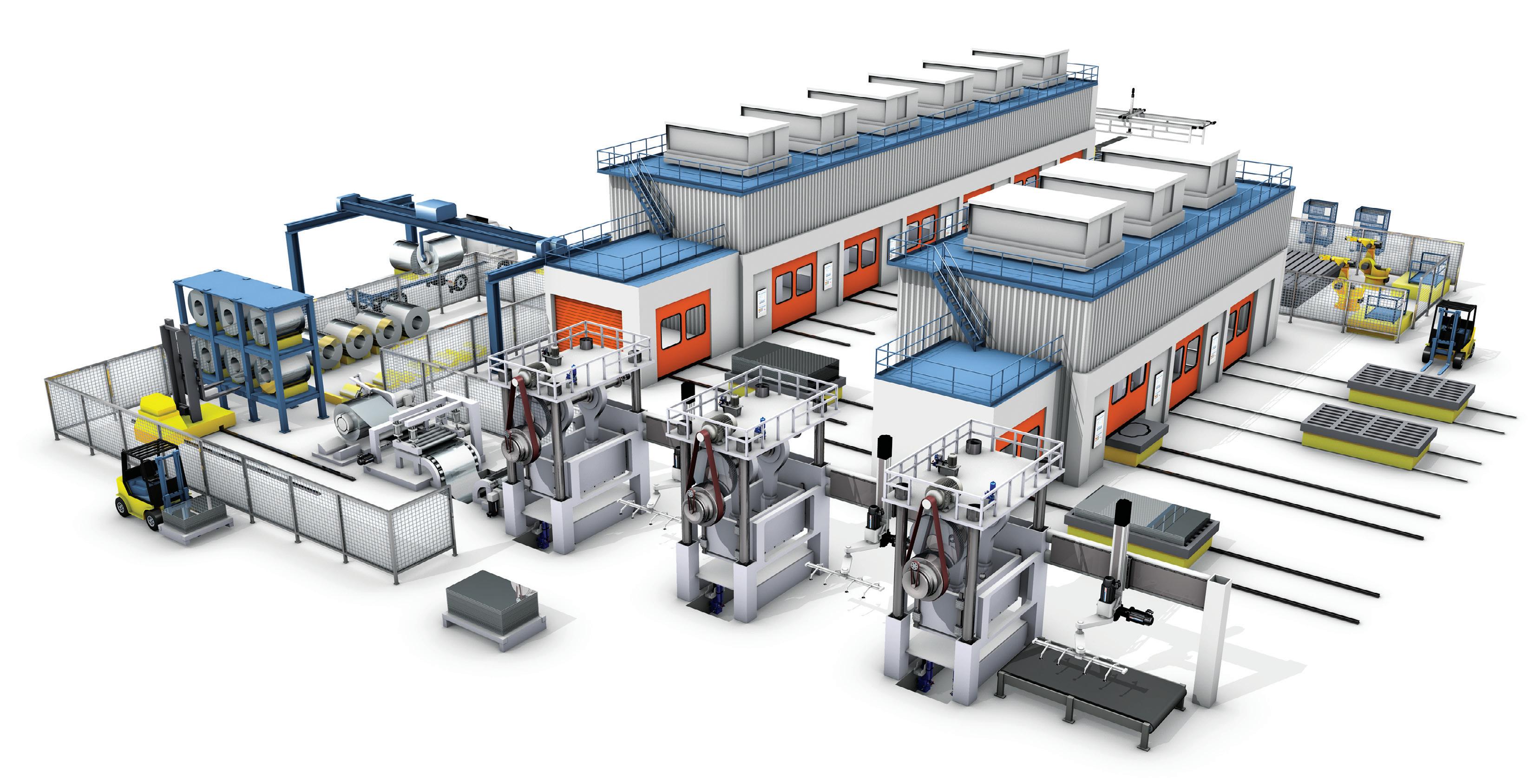
Modernization of automotive manufacturing processes
The automotive manufacturing industry is moving toward advanced, energy-saving solutions to modernize legacy systems and streamline the stamping process. As with many industries, automotive manufacturers value tradition and conventional machines and methods. Overcoming this traditional mindset to move toward advanced solutions can be difficult.
Although retrofits of cushion systems are less common as new presses enter the
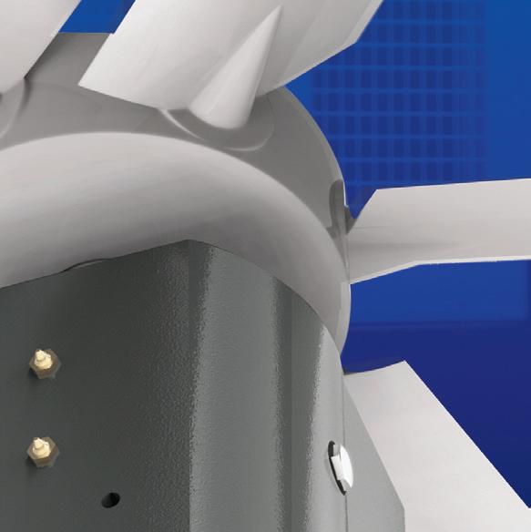
STAMPING
USES HYDRAULIC SYSTEMS IN AUTOMOTIVE MANUFACTURING TO CREATE CAR BODY PARTS WITH CONTROLLED PRECISION.
force with an actively controlled cushion system, ensuring precise force control and accuracy during the forming process.
The sheet metal stamping process is made up of multiple presses arranged side by side in a row with electromechanical automation continuously moving parts from one press to another. Each of these presses can complete a different operation on the parts including forming, trimming, piercing, and bending. The lead press, which completes the largest forming operation on the sheet metal into its general part shape, is often equipped with a hydraulic cushion system. These cushions provide a counterforce on the sheet metal to help prevent any tearing or wrinkling during the forming process. Hydraulic cushion systems offer superior power and control within
early or too late.
The precision that hydraulic components offer to the shaping of materials in metal stamping helps curate more control — a feat that pneumatic and mechanical systems are less successful at.
The more complex electromechanical cushion system solutions are considered less standard in the United States automotive manufacturing industry due to additional moving parts requiring extensive maintenance. There is a growing recognition and adoption of hydraulic systems in the industry due to controllability and modern exigency for energy saving options, so much so that newer presses are now being designed with these components as default.
market, some manufacturers are maintaining their legacy equipment in hopes of not disrupting their operations and to increase the press equipment’s life expectancy, all with modern demand and investment consideration. Due to this hesitancy, there is an opportunity to integrate and retrofit new technologies. A key argument for doing so is that retrofitting complete hydraulic systems into existing infrastructure can help companies balance demand and combat maintenance costs while still being able to reap the benefits of an optimized control.
Relying on legacy systems can lead to
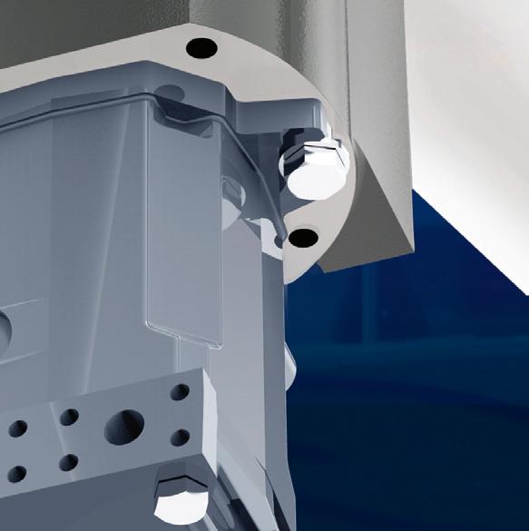
THE
PROCESS
MOTION SEQUENCE OF A DIE CUSHION

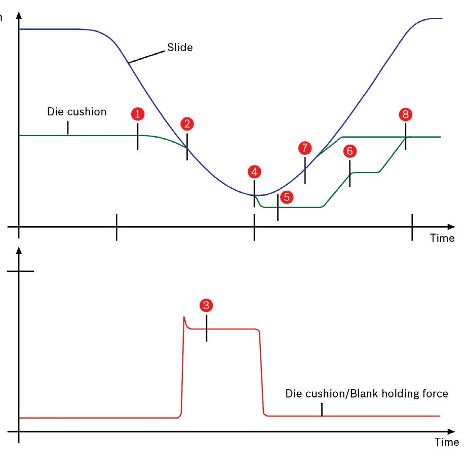

1. Start of the pre-acceleration
2. Automatic and low-impact transition from position to force control
3. Pressure build-up for the required drawing force with several linearly interpolated force and displacement intermediate points. Force progression during the drawing process is separately programmable for each cylinder module and depending on the drawing depth.
4. Decompression at bottom dead center
Variant 1:
5. Retraction at the bottom dead center of the die cushion to prevent material from springing back
6. Move to pick-up position (part removal)
Variant 2:
7. Closed retraction
8. Starting position
higher energy consumption due to the wear on the hydraulic parts. Leaks can impact the force of the system, making the hydraulic equipment much less efficient. Retrofitting outdated components in metal stamping heavily impacts the output quality and ultimately leads to higher productivity from the machine, increased cost-effectiveness, and greater precision.
Moving the industry forward
Discussions between automotive manufacturers regarding the advancement of research and development for new solu-
HYDRAULIC CUSHION SYSTEMS IN THE LEAD PRESS HELP PRODUCE SUPERIOR POWER AND CONTROL THROUGHOUT THE FORMING OPERATION.
approaches. A mixed system throttling for precise dynamic control combined with a direct hydraulic motor for energy recuperation achieves dynamic precision and energy savings. Other solutions can be too harsh on equipment, leading to increased wear, and higher maintenance costs.
Energy efficiency is another driving point for conversations about growth and expansion in the metal forming industry. The stamping process generates substantial energy through the cushion function, which is typically anticipated as heat removal. The industry is looking into ways to recapture this energy and transfer it back into the process, aiming to reduce energy consumption, lower operation costs and more. Finding the right balance between efficient and innovative processes that produce quality throughput will be a priority on both sides of the industry moving forward. Advancements in energy savings, streamlining hydraulic cushion systems and retrofit-
tions are promising. Technology that accommodates system functions should be welcomed, but with a clear understanding of how the industry continues to change.
Some large equipment manufacturers are moving the needle on what could soon be considered industry standard. They are using less widely adopted strategies, like deploying direct drive hydraulic solutions where the pump acts as a hydraulic motor, generating energy that can be fed back into the grid. Additionally, total hydraulic system designs can be more energy efficient with a focus on reducing heat generation and power consumption compared to exclusively standard throttling-based
ting legacy machinery are all essential parts to improving and developing the most efficient metal forming operation. If equipment manufacturers continue engaging in conversations with automotive manufacturers, hydraulic solutions can be optimized to meet the evolving demands of the industry. Evaluating total process parameters and condition of equipment is enhanced with diagnostic capabilities that can ultimately show the total cost of ownership of up-todate hydraulic cushion systems. FPW Bosch Rexroth boschrexroth.com
WHICH AIR COMPRESSOR CAPACITY CONTROL MODE IS BEST ?
Understanding the five control modes helps users find the most efficient setting on their industrial air compressor.

BY: Ron Marshall CONTRIBUTING EDITOR
J AIR COMPRESSORS CAN USE ONE OF FIVE CONTROL MODES. KNOWING WHICH IS MOST SUITABLE FOR THE DIFFERENT TYPES OF COMPRESSORS IS NECESSARY FOR EFFIICIENT OPERATION.
THERE ARE FIVE DIFFERENT CAPACITY CONTROL MODES available for use with North American-built large industrial air compressors. It pays to know how each mode works, especially if you operate or service air compressors or happen to have your compressors operating in one of the least efficient modes.
The five different capacity control modes for compressors each offer different levels of efficiency:
1. Start/stop — simply starting and stopping the compressor using pressure switch control. Very efficient but can only be used on small compressors.
2. Modulation — choking of the inlet flow of air using an inlet valve. Very inefficient at part loads.
3. Load/unload — Loading and unloading a compressor using inlet valve control and sump blowdown. Moderately efficient if the compressor has access to large storage.
4. Variable displacement — Opening up ports in the screw to bypass the compression element. Good efficiency if set up correctly.
5. Variable speed drive — Speeding up or slowing down the compressor to vary its output flow. Most efficient operation at part load if applied properly.
START/STOP MODE
The simplest method of controlling a compressor is Start/Stop mode using pressure switch control. This control simply turns on the compressor to run at full load when the pressure hits a lower pressure level — and turns off the compressor when the pressure hits a higher-pressure level. Figure 1 shows a compressor operating in this mode. Because it is a lubricated screw compressor, there is a period of cooldown operation between cycles where the compressor runs unloaded (consuming power) for a set time period.
If used on screw compressors, the storage capacity needs to be very large, limiting the start/stop frequency to no more than 4 to 6 per hour at worst case conditions (50% loading). Often a cooldown timer will run, as in the graphic, which reduces the efficiency of the compressor because there are
periods when the compressor is running unloaded, consuming about 30% power but producing no air. Some modern screw compressors have adaptive control that will reduce or eliminate unloaded run time if motor starts have not been exceeded.
Start/stop control is an excellent way to operate a spare compressor that is not used often. The unit turns on only when required and turns off when it is not needed.
MODULATING MODE
The least efficient method of controlling a compressor at part load is using modulating mode by way of pneumatically controlled inlet valve control.
With this mode, a pneumatic system detects the compressor discharge pressure and compares it to a fixed pressure setting. If there is a difference, an inlet valve will operate to open or close an inlet valve to control the flow output of the compressor — and return the discharge pressure to the setpoint. In this mode, the power only turns down 3% for every 10% of flow reduction, resulting in 70% power consumption at zero flow for compressors using straight modulation — extremely inefficient.
This mode of operation is available only on lubricated compressors, and usually on compressors built in North America. Due to high power costs, European companies figured out a long time ago that the resulting inefficiency is way too costly.
Companies soon realized the resulting inefficiency at lower levels of flow, so unloading circuits are added to compressors to unload them when the flow drops to less than 40% flow. When a compressor hits below this level, a pressure switch trips and unloads the compressor to about 30% of full load power while producing no air; this is more efficient than keeping the compressor modulated.
If your compressors are operating in modulation mode, it is recommended that you have someone look at your system to optimize the efficiency. This usually results in some more storage receiver capacity being installed (modulation can operate with no storage capacity) and the compressors switched to load/unload mode, which is often more efficient.
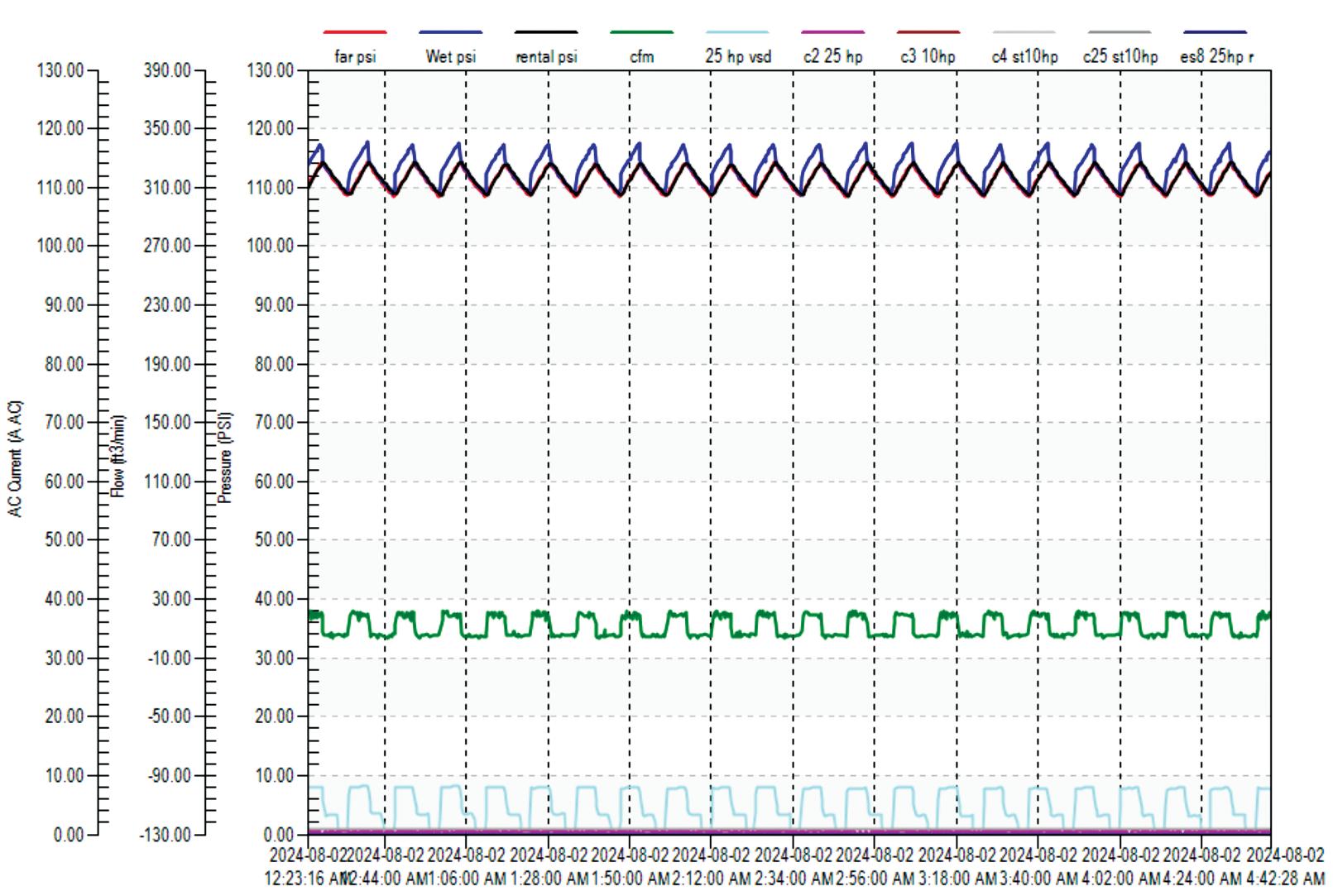
J FIGURE 1. START/STOP MODE (WITH NO UNLOADED OPERATION) IS VERY EFFICIENT BECAUSE THE COMPRESSOR OPERATES FULLY LOADED, WHICH IS THE MOST EFFICIENT POINT, OR STOPPED, CONSUMING NO POWER. BUT THIS MODE IS HARD ON THE COMPRESSOR AND MAY RESULT IN EXCESSIVE MOTOR STARTS, RISKING MOTOR BURNOUT. FOR THIS REASON, THIS MODE CAN ONLY BE USED FOR SMALLER COMPRESSORS, USUALLY UNDER 20 HP, AND TYPICALLY RECIPROCATING TYPES. WHEN USED THE PRESSURE BAND IS USUALLY VERY WIDE (30 PSI OR MORE) AND THE STORAGE RECEIVER CAPACITY LARGE. LIMITING THE NUMBER OF MOTOR STARTS TO LESS THAN 10 PER HOUR IS ADVISED.
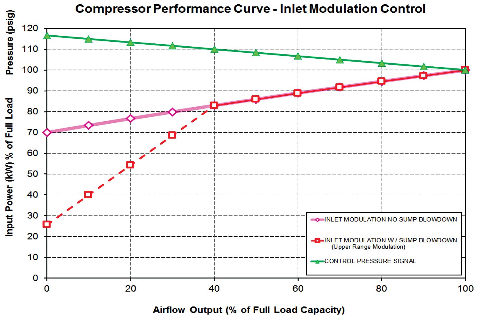
J FIGURE 2. POWER VERSUS CAPACITY CURVE FOR A COMPRESSOR RUNNING IN MODULATING MODE SHOWS THE POWER TURNDOWN YIELDS ONLY 3% POWER REDUCTION FOR EVERY 10 PSI. THIS IS THE LEAST EFFICIENT MODE IN WHICH TO OPERATE LUBRICATED SCREW COMPRESSORS, ESPECIALLY IN SYSTEMS WITH MULTIPLE UNITS RUNNING.
LOAD/UNLOAD
A moderately efficient method of controlling a compressor at part load uses load/ unload mode with adequately sized storage receiver capacity.
With this mode, a pressure switch, or electronic control, is used to provide load and unload signals to the compressor. When the pressure hits the load setting, the compressor inlet valve opens and the
compressor goes to full load, its most efficient point. The added capacity will push the system pressure up until the unload setpoint is reached. When unloading, the inlet valve closes and the compressor lubricant sump is blown down, producing zero flow but keeping the compressor running at about 30% of full load power.
For lubricant free compressors, there is no sump to blow down, so the unload operation is quite quick and efficient. For lubricated compressors, the blowdown takes time to avoid foaming the lubricant, and while blowing down slowly to the final level, the compressor consumes more than desired power. For this reason, large storage should be installed to reduce the load/ unload cycles, reducing the frequency of blowdowns. We can see from Figure 3 if only 1 gal per cfm compressor capacity worth of storage is installed, the compressor consumes more than 80% of its rated power when at an example load of 40%. If the storage capacity is 10 gal per cfm, the resulting cycles will be 10 times less, so the average power consumption would reduce to 60%, saving considerable power.
Typical recommended storage size is between 3 to 5 gal times the rated cfm capacity of the largest compressor in the system. With larger sized storage, the use of load/unload with start/stop control using unload timers can save even more power.
If you are running load/unload control using lubricated screw compressors with small storage, consider upsizing your system storage to reduce compressor cycles. A good way of detecting lack of storage is to time your compressor cycles. If the load/ unload cycle time is less than 2 minutes, your storage is likely too small. Lubricant free compressors do not need such large storage to run efficiently, however there is still a maintenance benefit in reducing the number of cycles.
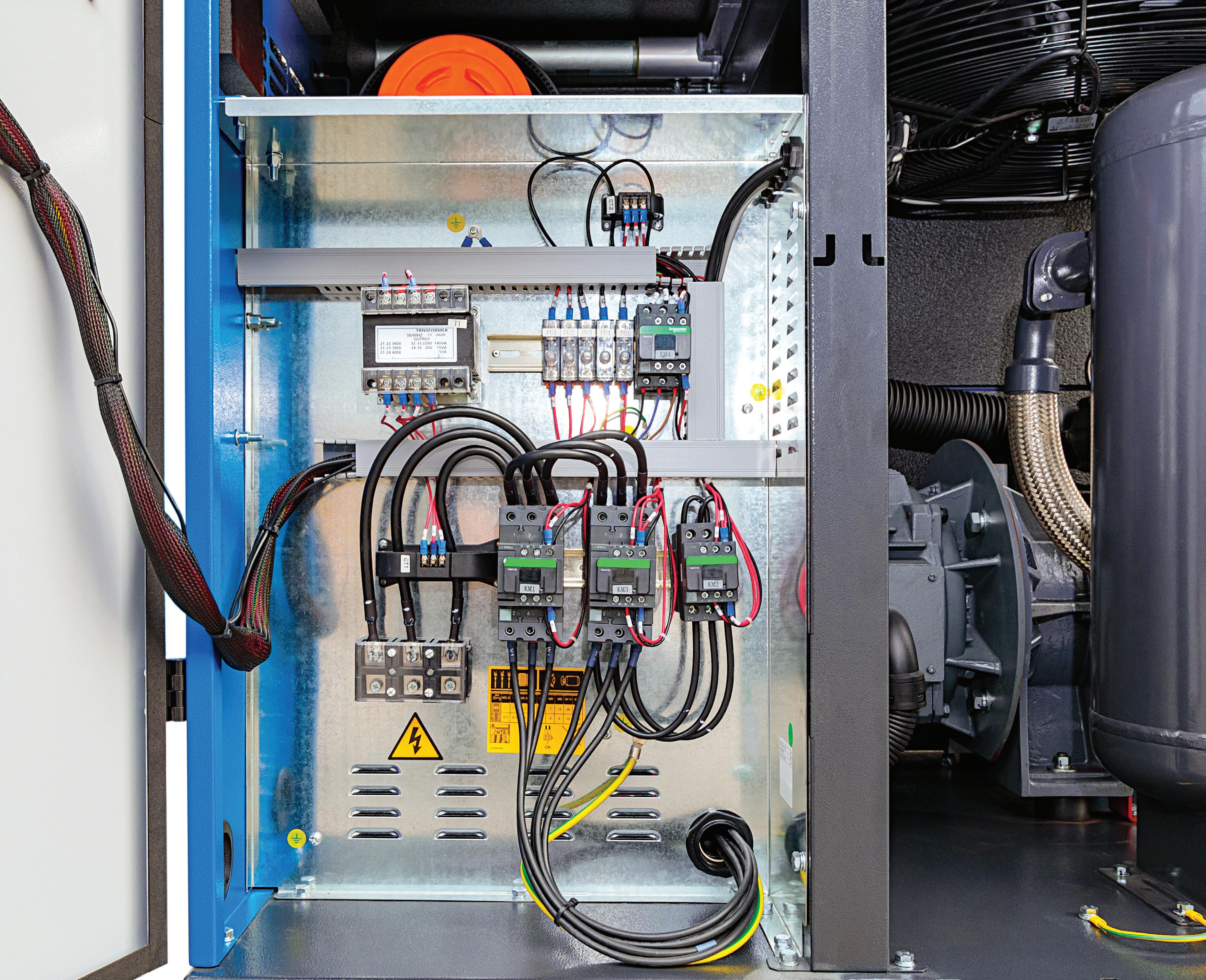
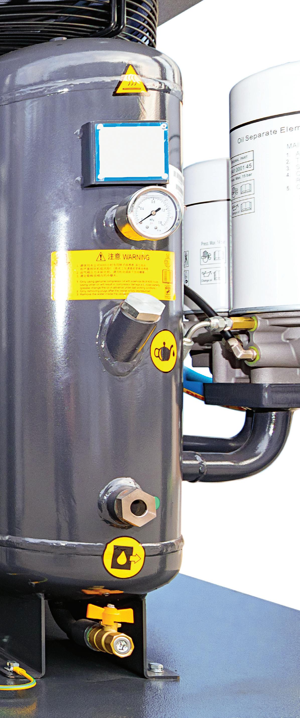
VARIABLE DISPLACEMENT
Figure 4 shows one design that was available in the past for variable displacement compressors. The dial shows that this compressor is running with the variable displacement valve (this manufacturer calls it a spiral valve) that is partly open at about
80% capacity. In the background we can see its inlet valve is wide open, the preferred condition.
For this compressor, the operation of this control is problematic because the site operators are running out of compressed air capacity. The control system on this compressor has a fault, reducing the output capacity of the unit. A sharp eye in this case can detect the problem and fix it.
The problem with newer controls is that valve position is not so easy to detect, however, because the spiral valve indicator is simply a bolt that sticks out of the screw element, and the inlet valve for this manufacturer is now a poppet style with no mechanical indication of its position.
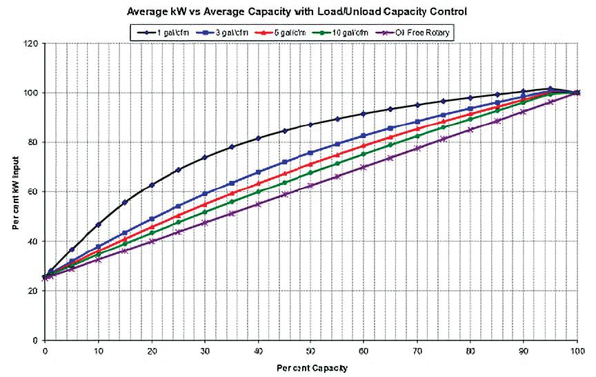
J FIGURE 3. THE POWER VERSUS CAPACITY CURVE FOR A LUBRICATED SCREW COMPRESSOR RUNNING IN LOAD/UNLOAD MODE SHOWS THE POWER TURNDOWN YIELDS ROUGHLY 7% POWER REDUCTION FOR EVERY 10 PSI — MAKING THIS A MODERATELY EFFICIENT MODE IN WHICH TO OPERATE. THIS MODE REQUIRES ADEQUATE EFFECTIVE STORAGE CAPACITY; SMALL RECEIVER SIZE CAUSES INEFFICIENT RAPID CYCLING.
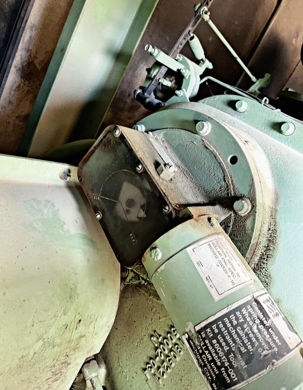
J FIGURE 4. CONTROL FAILURE HAS CAUSED THIS VARIABLE DISPLACEMENT CONTROL TO STICK PARTLY OPEN, REDUCING THE CAPACITY OF THE COMPRESSOR.
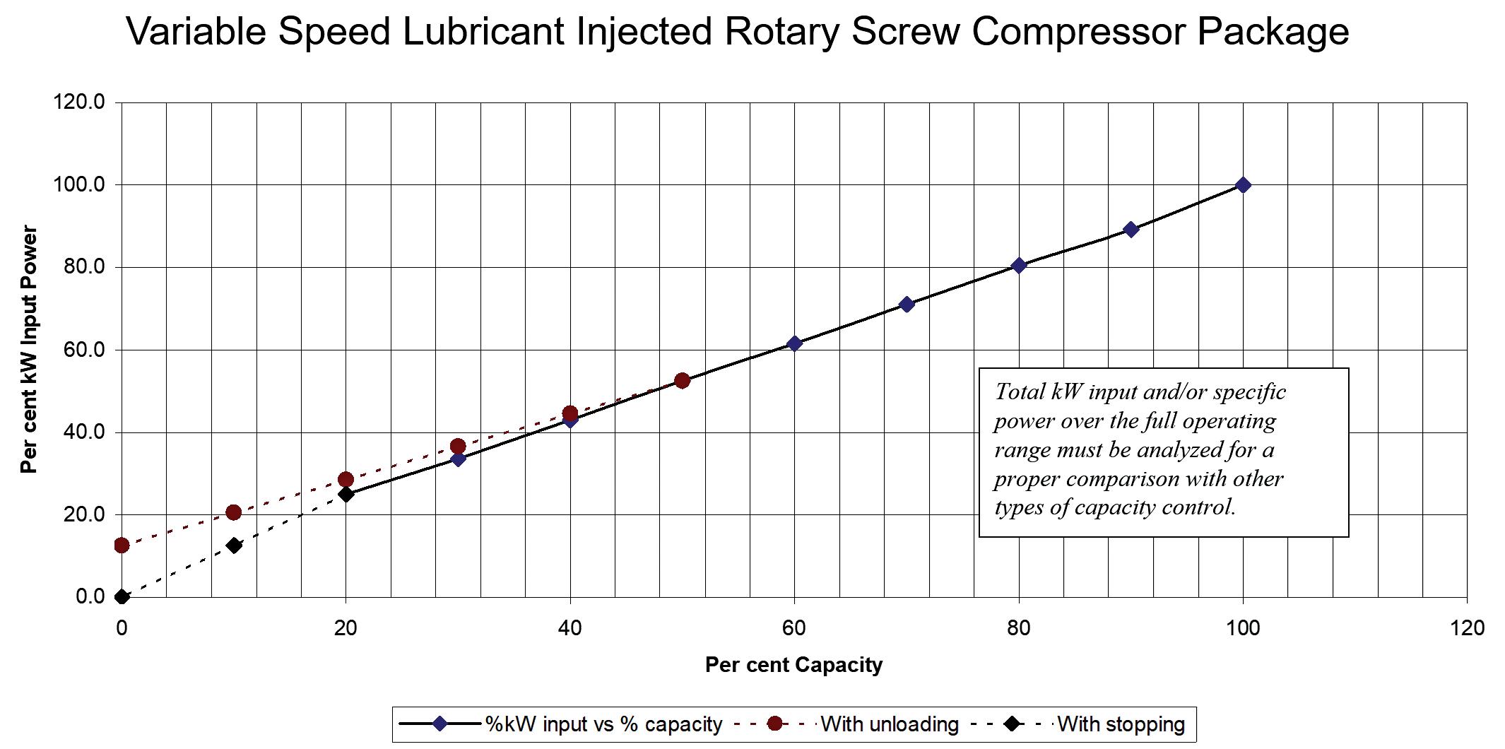
FIGURE 5. THE POWER VERSUS CAPACITY CURVE FOR A LUBRICATED SCREW COMPRESSOR RUNNING IN VARIABLE SPEED MODE SHOWS THE POWER TURNDOWN YIELDS ROUGHLY 1:1 POWER REDUCTION MAKING THIS A VERY EFFICIENT MODE IN WHICH TO OPERATE. THIS MODE STILL REQUIRES ADEQUATE EFFECTIVE STORAGE CAPACITY WHEN INSTALLED IN MULTIPLE COMPRESSOR SYSTEMS.
In these cases, we must measure the compressor input power to determine if it is producing full flow — and if possible, measure the output flow with a properly installed flow meter. Lower than rated amps (when the discharge pressure is lower than the compressor setting) usually means low output flow, possibly pointing to a control problem.
VARIABLE SPEED
A very efficient method of controlling a compressor at part load is using variable speed mode.
With this type of compressor, an electronic drive is fitted to a specially designed compressor with air end components matched to the intended speed range to maximize efficiency. With positive displacement compressors, every revolution of the screw element shaft will produce a constant volume of compressed air, so therefore if the shaft rotations per minute change, so will the flow output of the compressor. With variable speed drive compressors, the power consumption varies nearly one-toone with the change in flow output, making this type of compressor a very good choice for efficiently matching varying loads.
Variable speed compressors can be lubricant injected style or lubricant free. This type of compressor is controlled with an electronic control that senses the output pressure and speeds up or slows down the compression element to maintain a con-
stant pressure output using PID control. VSD or VFD compressors (the term is interchangeable in the industry) can operate successfully with smaller storage receiver sizes, but good control still requires some storage, especially if the VSD compressor must operate with other fixed speed compressors.
The typical recommended storage size is between 1 to 3 gal times the rated cfm capacity of the largest compressor in the system. With larger sized storage, the changes in pressure when compressors are switching on and off is slowed down substantially, making control less complicated.
It is important to size VSD compressors correctly so that they do not run near the lower end of their speed range for significant hours. It is also important to sized the VSD compressor as the largest compressor in a system of multiple compressors, or a problem called control gap will occur. Typically, the VSD needs to be one or two sizes larger than the compressor with which it must work. The variable band of the compressor must be equal to or larger than the largest fixed speed compressor.
It is important to keep VSD compressors cool and clean to avoid overheating problems that might affect the reliability of the electronic drive. Most often, the installation of a VSD compressor will save significant energy by almost eliminating inefficient unloaded run time in compressed air systems — and stabilizing system pressure to lower than typical levels. FPW
J
Italian machine builders are set to showcase their cutting-edge ‘Breaking Necks’ solutions and technologies

Italian machine builders are the key to unlocking your strategic business potential.
How are end users leveraging Italian machinery to advance their operational goals and address significant industry trends? Machines Italia’s Spring 2025 issue will explore key trends across various sectors utilizing Italian machinery, including advancements in automation, environmental sustainability, and the increasing demand for flexible and adaptable machinery. For more details, visit machinesitalia.org


GEARING UP FOR BAUMA 2025
Billed as the largest trade fair for the construction industry in the world, bauma returns to Munich April 7-13.
Edited by Mary C. Gannon, Editor-in-Chief
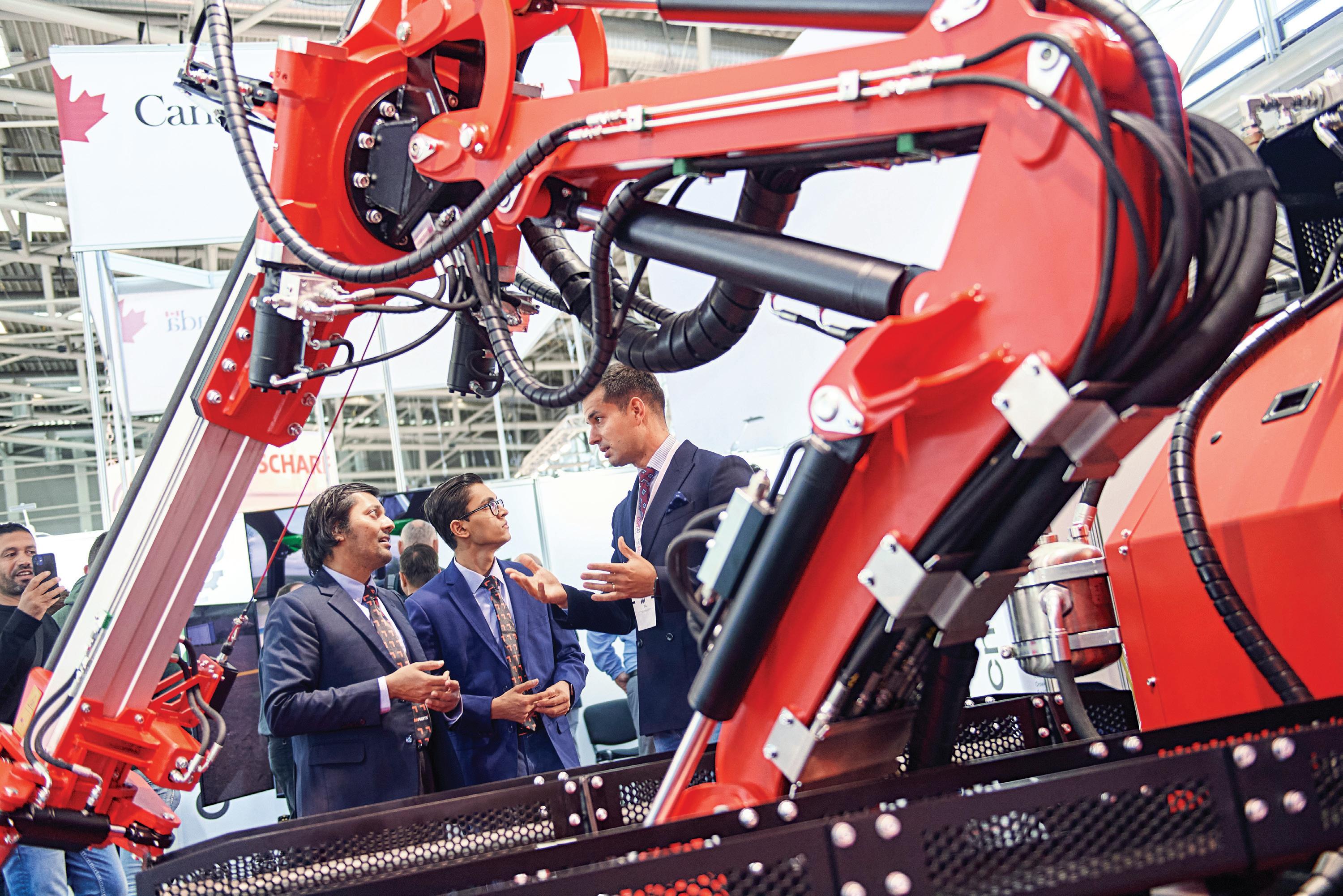
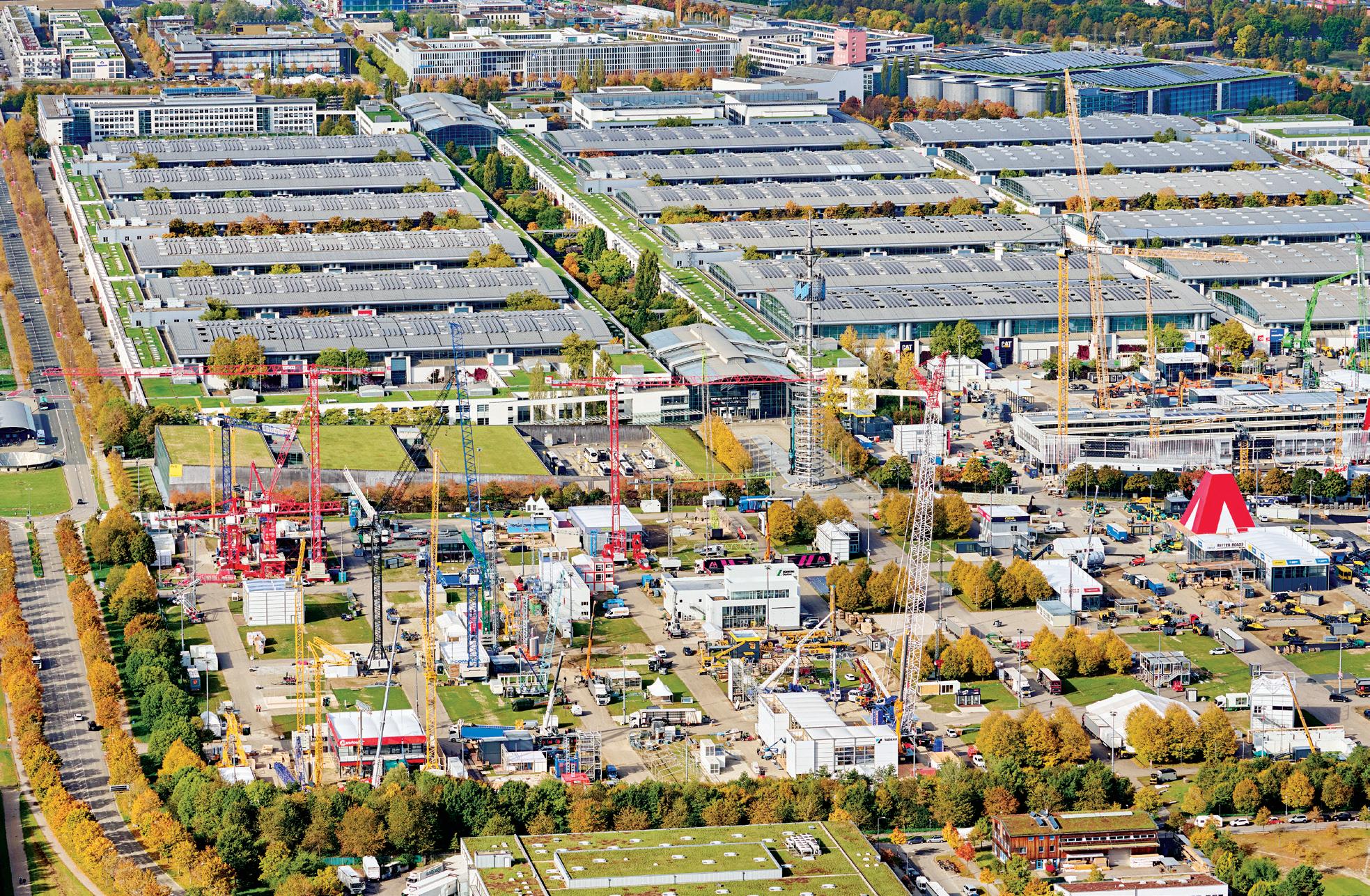
Construction is well under way for bauma 2025, as several key machine manufacturers have already built their outdoor exhibits late last year, and more are descending on the Munich exhibition center throughout the coming months. Nearly 4,000 exhibitors are signed up for the event that runs April 7-13, with about 200 companies highlighted under the hydraulics space.
Billed as the world’s leading trade fair for construction machinery, building mate-
rial machines, mining machines, construction vehicles and construction equipment, bauma will continue to focus on digitization and sustainability. As a result, these themes will be reflected in the five key topics that bauma will address: climate neutrality, alternative drive concepts, networked construction, sustainable construction, and mining challenges. From Monday to Friday, the bauma Forum will focus on one of these key topics. The program will consist of brief presentations, panel discussions and keynote presentations. Exhibitors will also present products and innovations from these areas.
Nicole Schmitt, Exhibition Director of bauma, has said that the event is on track to be once again the largest show for the mobile machine industry. “We are very pleased with the overall positive feedback
from the industry,” Schmitt said. “But I can already say that we are on the right track on the exhibitor side.”
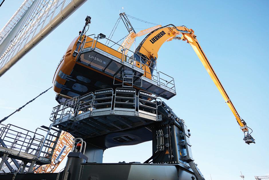
On the OEM side, numerous well-known companies will once again use bauma to showcase their products. The returning companies include Volvo, Deutz, Liugong, CNH, Skyjack and JLG. Joining their ranks for the first time are such companies as Fortescue, DSI/Sandvik, HG—100% electric dumpers, EXiron AG, Gravis Robotics AG, Metso Oyj, rockrobot oy, Wabtec Corporation and WEICO GmbH. Around 150 new exhibitors will be at bauma 2025 as well.
Key fluid power exhibitors will include Argo-Hytos, Bosch Rexroth, Bucher Hydraulics, Cassappa, Danfoss Power Solutions, HAWE, Husco International, Hydac International, HydraForce Hydraulics, Hydreco
Hydraulics, Hydro Leduc, Intertraco, Kawasaki Precision Machinery, Linde Hydraulics, Marzocchi Pompe, Moog Construction, Parker Hannifin, Rheintacho, SIKO, Spir Star Stucchi, Sun Hydraulics, Walvoil, Webtec, and many more.
Machine innovations take center stage
In networked construction, digital technologies and communication systems are integrated into the construction process, which improves collaboration and efficiency. For example, attachments supply process data and communicate with the respective carrier machines. A standardized digital language is required for this communication to also work regardless of the manufacturer. Thanks to a new common universal protocol, the carrier machine recognizes which attachment is to be used, which parameters it needs to function, and whether it is even suitable for use on this machine. “Accidents caused by incorrectly closed quick hitches, unsuitable hydraulic pressure or incorrectly dimensioned attachments can thus be reliably avoided,” said Dr. Darius Soßdorf, Managing Director of the MiC 4.0 working group at the German Mechanical Engineering Industry Association (vdma). The working group includes manufacturers of construction machinery and sensors, software
companies, and construction firms.
A main focus of the event will be on advancing digitalization of construction machinery, where users receive increasing amounts of data which not only show them the condition of the machines, but also provide valuable information on their performance and work quality. More efficient fuel routes can be developed based on current consumption data, while machine deployment can be optimized by accurately recording respective capacity utilization. A new function of the telematics system from Bobcat shows that the information flow does not have to be a one-way street from the machine to the operator. The engine of wheel loaders, mini excavators, etc. can be remotely deactivated — and also reactivated — by the owner with just a few clicks. That prevents unauthorized use and theft, which can result in lower insurance premiums, among other things.
On the basis of digital information, and given the shortage of skilled workers, even less experienced machine operators can avoid slight errors and accidents and achieve very good work results. For example, the construction machinery manufacturer Develon, formerly known as Doosan Construction Equipment, together with surveying specialist Leica Geosystems, recently started offering 3D machine control as a retrofit option for one of its crawler excavator models. Design information and real-
time cut/fill indications are displayed on the control panel in the cab so that the driver can carry out the excavator work exactly according to the reference model.
Sensors are a prerequisite for the digitalization of construction machinery, including developing assistance and autonomy systems. For example, they register the boom and bucket position, are used for fluid management, or help detect structural loads and damage.
Focus on research and innovation
Eleven research institutions will present innovative projects at the bauma Science Hub. Among other things, the Technical University of Munich will present autonomous solutions for bulk goods transportation and a paving robot. The University of DuisburgEssen will demonstrate a cable robot for precise use on construction sites, and the Technical University of Dresden will present ways to avoid accidents by using a mobile excavator that can recognize human beings. bauma 2025 will also offer young, innovative companies the opportunity to present their ideas. Almost 50 start-ups have registered to showcase their innovations and developments related to the main topics of bauma, including mobile robot technologies, the development of digital twins of construction sites, alternative drive systems, ultrasonic technology in concrete production, autonomous crane solutions for digital construction sites in rough terrain, as well as end-to-end and other software solutions that help companies in the office and on the construction site.
Additionally, hydrogen, efuels, battery electrics, and other innovative drive concepts will be explored throughout the show floor and daily presentations. bauma highlights the growth of battery electrics, with data from consulting firm IDTechEx predicting that the global market for electric construction machinery will be worth $105 billion by 2042. For hydrogen, one OEM presented two hydrogen combustion engines in 2022, and will have series production this year. Live demonstrations of such machinery will be announced in March. FPW
BAUMA IS THE WORLD'S LARGEST TRADE SHOW FOR CONSTRUCTION AND MINING EQUIPMENT, WITH NEARLY 4,000 EXHIBITORS FOR THE WEEK-LONG EVENT.
Hydraulic flow monitor
Webtec webtec.com
The heavy-duty yet compact CTA series flow monitor for hydraulic systems now features a 4-20 mA output. This device can monitor and transmit oil flow and temperature data through a J1939 CAN-bus interface. Adding a 4-20 mA (3-wire loop) analog output
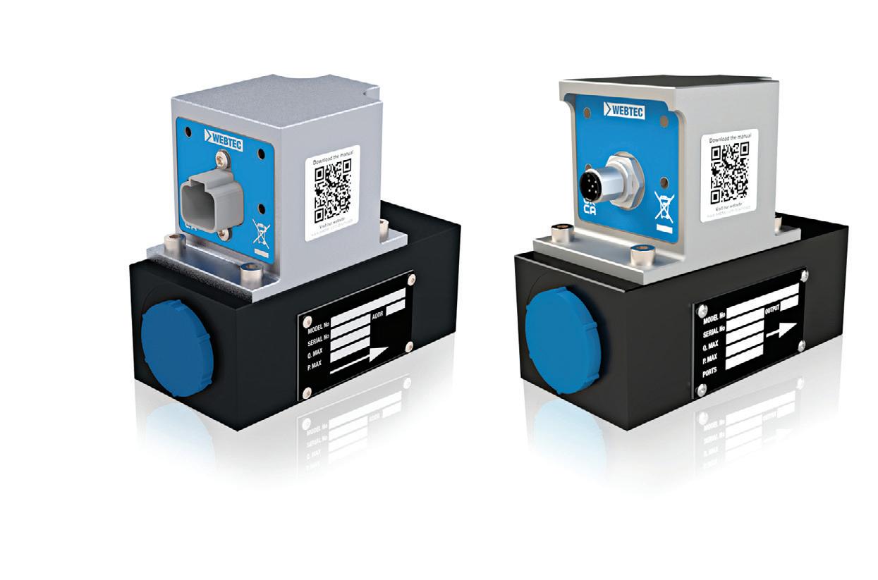
for flow reporting enables easy permanent installation on industrial and on/off-highway machines. The rugged flow monitor is suitable for closed-loop control, real-time diagnostics, safety interlocks, and inclusion in predictive maintenance/IoT systems to reduce downtime or facilitate autonomous vehicle operation. CTA series flow monitors are fully EMC-compliant, resistant to water spray and steam cleaning (IP6K9K protection rating), and unaffected by heavy vibration, making them a valuable addition to numerous vehicle applications.
Editron electric motor
Danfoss danfoss.com
Bio-Ultimax 1200LT hydraulic fluids

Renewable Lubricants Inc.
RenewableLube.com
Bio-Ultimax 1200LT hydraulic fluids are biodegradable, biosynthetic formulas that stay pumpable at –40° C (–40° F) with a pour point of –60° C (–76° F). They minimize cold-weather issues like slow startup, seal leaks, and moisture intrusion. Available in multiple ISO grades, they offer oxidation resistance, antiwear performance, and compatibility with high-pressure systems. Their high viscosity index enhances shear stability and load capacity, while zinc-free formulations lower toxicity, reduce bioaccumulation, and meet EPA guidelines for Environmentally Acceptable Lubricants. They also satisfy DIN 51524 Parts 2 and 3, Parker-Denison HF-0, and Eaton-Vickers M-2950-S for demanding hydraulic applications.
Premium flexible braided hydraulic hose

Continental continental-industry.com
The X-Life XCP5, a flexible braided hose, is designed for highpressure hydraulic systems requiring extra abrasion resistance. Part of Continental's ISO 18752–compliant portfolio, XCP5 suits applications in agriculture, mining, construction, manufacturing, and energy, especially those needing tight bends. It operates between –40° and 212° F and is available in three sizes: 1/2, 3/8, and 3/4 in. Users can pair the hose with Continental’s one-piece B2-type fittings, which feature an optional ArmorPlate coating that resists corrosion for up to 1,000 hours. The fittings’ single-piece steel construction and interlocking bite-to-wire design minimize leaks and enhance coupling reliability.
The Editron EM-PMI375 690-V electric motor uses synchronous reluctance-assisted permanent magnet technology, functioning as both a motor and a generator. It is designed to work with the Editron EC-C1700B inverter, offering a comprehensive system solution for 690-Vac and 1,050-Vdc applications, including winches, cranes, marine vessels, and mining and material-handling equipment. This new motor shares the same shape and form as the EM-PMI375 500-V motor, maintaining the same robustness, longevity, and standardized options. Like its 500-V counterpart, the EM-PMI375 690-V motor is smaller, lighter, and more efficient than traditional products, achieving up to 96% efficiency across its operating range. Specifically developed for demanding applications, the motor features a compact, sturdy aluminum frame structure with an ingress protection rating of IP67.
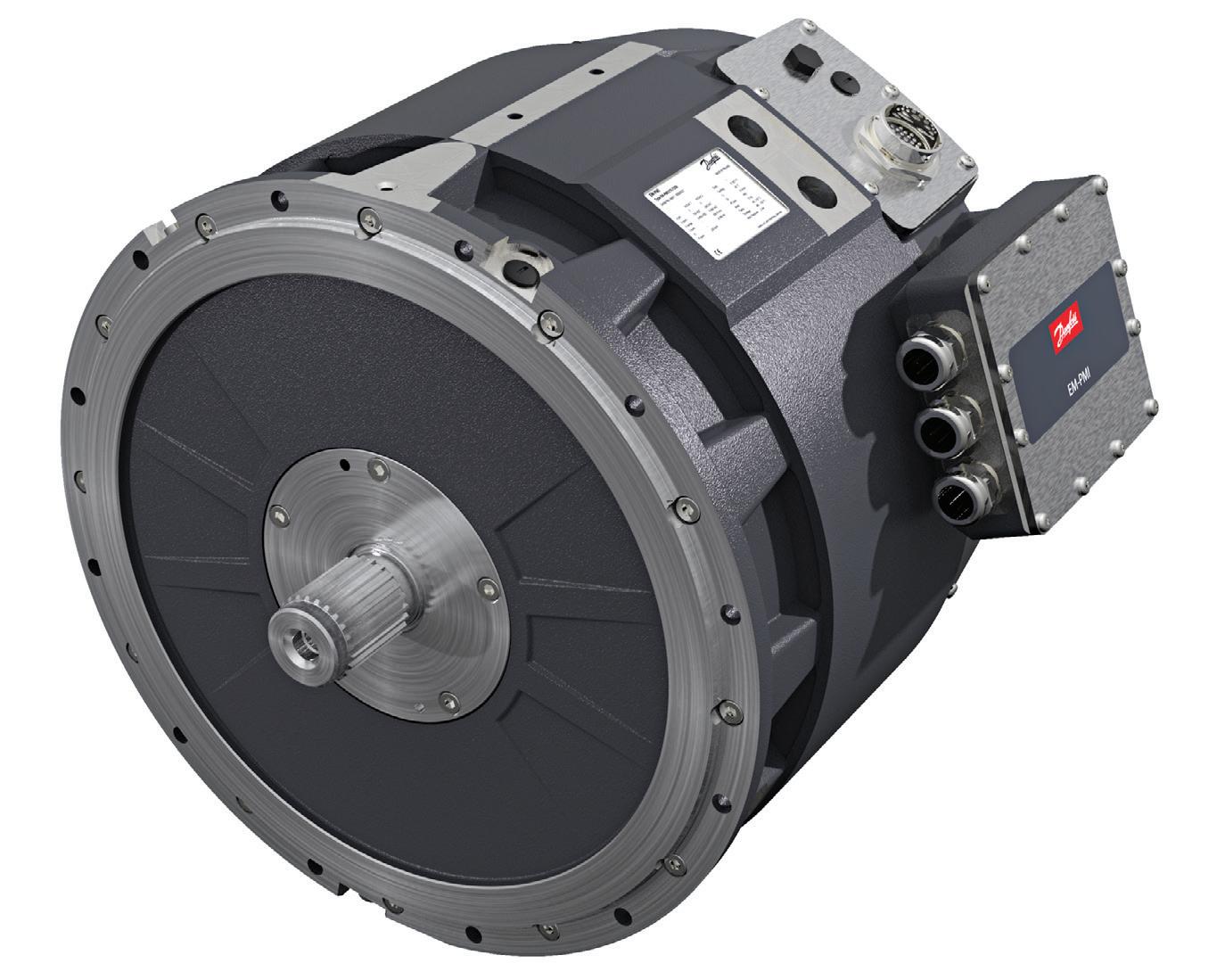
Modular desiccant air dryer
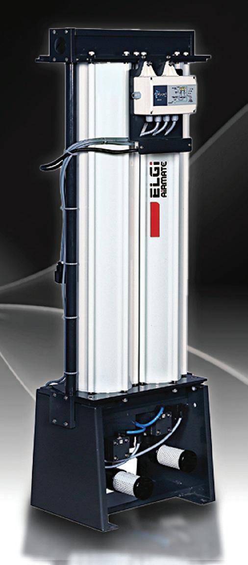
ELGi North America elgi.com
The Airmate HLD series modular desiccant compressed air dryer is designed for ultra-dry compressed air applications. It achieves ISO 8573-1:2010 Class 2 air quality and maintains –40° C pressure dew points to meet industries’ moisturesensitive requirements. The dryer uses a modular twin-tower heatless drying system, alternating between two towers for a continuous, high-quality air supply. Air passes through one tower to absorb moisture while the other regenerates the desiccant. The system runs on a fourminute cycle to ensure efficient drying.
The Airmate HLD series also includes an adjustable purge optimizer and an optional dew point stretch cycle to tailor operation efficiency based on moisture needs and reduce energy consumption. It is available in sizes from 10 to 375 cfm and easily integrates into existing systems.
Vented linear position sensors
NewTek Sensor Solutions newteksensors.com
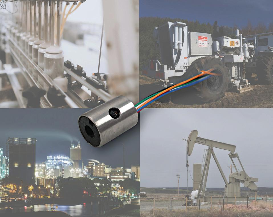
The vented M-375 linear variable differential transformers (lvdts) measure piston position in high-pressure hydraulic cylinders operating up to 30,000 psi and at –65° F to 400° F. The vented design equalizes pressure, preventing damage from imbalances. Noncontact measurement preserves accuracy and minimizes wear, while a 3/8-in. diameter suits tight spaces. Used in industrial automation, power plants, oil/gas drilling, and materials testing, they support measurement ranges from ±0.025 to ±2.0 in. with ±0.25% non-linearity. Compatible with standard differential input conditioners like the NTC-6000 Qwik-Cal, the M-375 series outputs DC voltage, current, or RS-485 digital signals for critical hydraulic system feedback. FPW

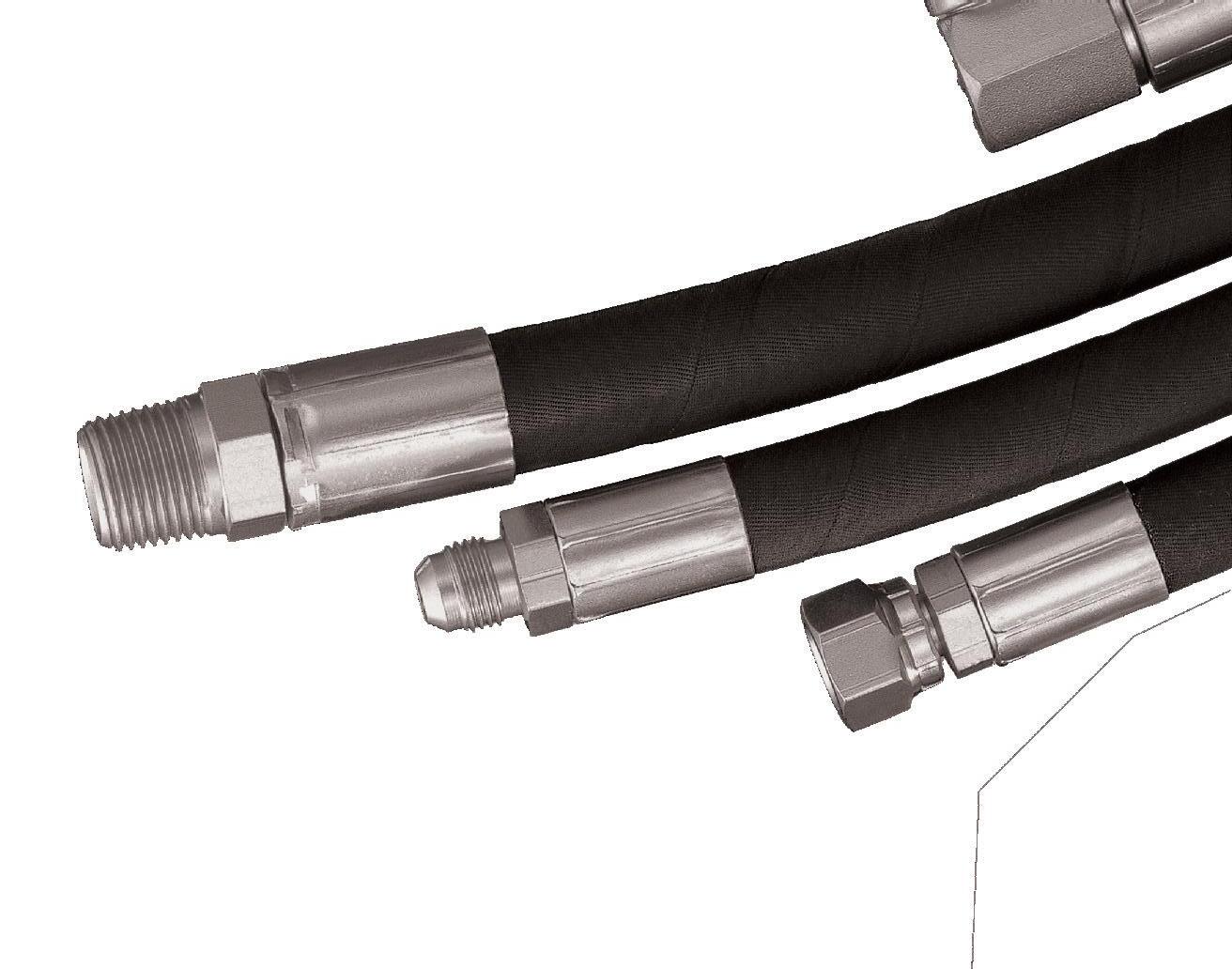

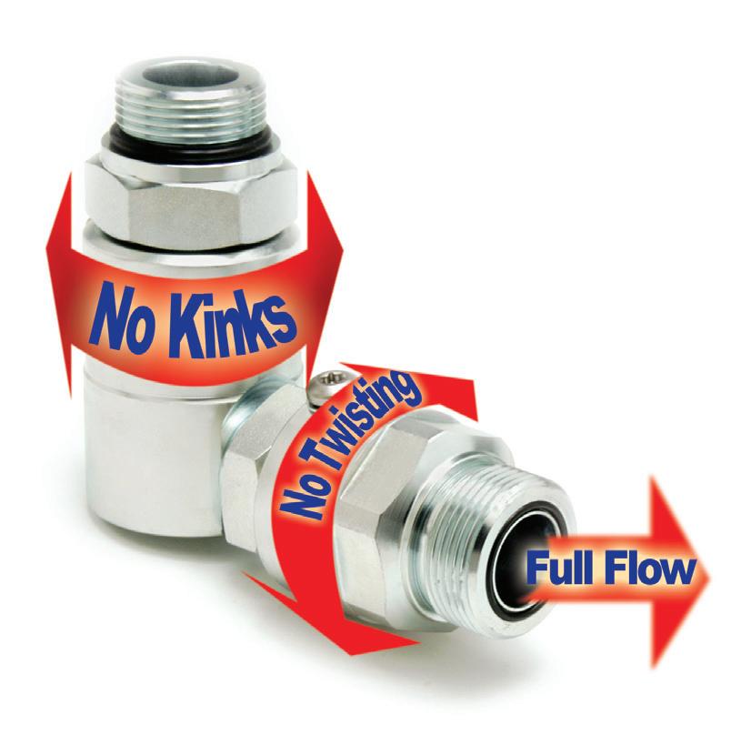

Robert Sheaf • Founder of CFC Industrial Training
Directional valve replacement causes return line filter failure
WHILE LIFTING A BENT PLATE from a steel plate bending press machine, the accumulator safety unloading valve was damaged and the magnet on the plate lifting crane failed (see circuit attached). They repaired the crane magnet and replaced the damaged hydraulic valve. On start up, they bled the system of air and cycled the crane hydraulic system. When they shut off the power to the crane and hydraulic system, the spin-on return filter element blew off, spilling oil all over the floor.
The technician installed a new clean element, which promptly blew off again when the system power was shut off. Engineering decided to increase the flow rating of the filter head and element assembly. When the larger assembly was installed, excessive leakage occurred immediately between the head and the spin-on element when powering down the hydraulics.
They reviewed the PLC program and found it was sequencing correctly, as originally designed. They decided to remove the complete filter assembly. On this try, they blew the breathers off the top of the reservoir on shutdown.
What would you do next? We welcome responses of all kinds directly to Bob Sheaf at rjsheaf@cfc-solar.com or to mgannon@wtwhmedia.com The solution will be provided in conjunction with next edition of Fluid Power World and will be published online in March.
Solution to is heat causing these cylinders to move out of sync?
THE PROBLEM CAUSING THE CYLINDERS TO BIND was created by one of the flushing valves (#10 on the schematic) that were left open during the shutdown. With long pipe runs, it is common practice to install flushing shut-off valves to allow clean fluid to flush the lines and cylinders as preventive maintenance. During the shut-down, one of the maintenance team members did not completely close off one of the flushing shut-off valves after performing maintenance. FPW

Accumulator Circuit Operation


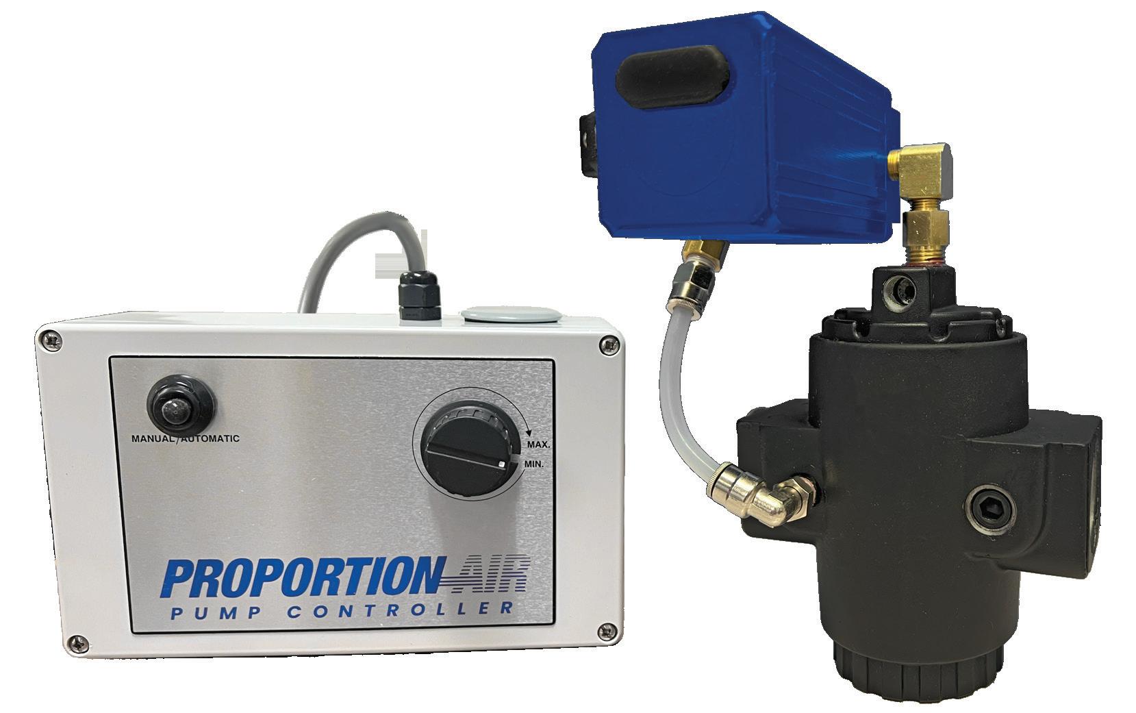


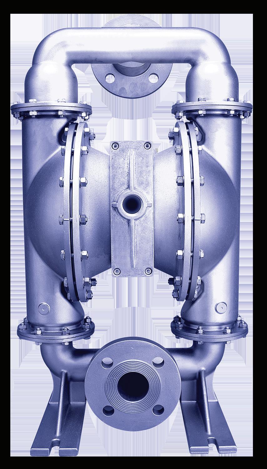


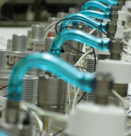

Precision Control Solutions
Designing efficient systems involves much more than simply understanding a few basic principles. There is a true art to balancing the specific requirements of an application in order to achieve the desired goals in the best possible way. Help us understand the unique needs of your application and together, we’ll develop something that surpasses what any of us could have done alone.
Contact your distributor to learn more, or visit clippard.com to request a free catalog and capabilities brochure.