StudioanFieraexerciseingridshelldesignXavierBarnett1341028DesignStudioC20-TheShapeofWine
Table of Contents 4 Precedent Study 6 Paper Exploration 8 Paper Model Views 10 Mesh Exploration 12 Elastic Gridshell Digitisation 14 Final Elastic Gridshell 16 Pneumatic Shell Formfinding 20 Structural Analysis 22 Case Study Precedents 26 Initial Digital Model 28 Final Digital Model 30 Physical Model Development
page 5
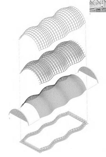
There are a number of takeaways from the precedent study conducted in order to understand how a successful eleastic gridshell can be successful. A key aspect is trhe bracing, with clear bracing always around the entrance. This allows for a clear entrance and minimising outward forces from the gridshell. Furthermore, the structure itself shall be braced at continuous centres through the form. There must also be points of anchorage on the ground, transferring the load and minimising outward forces. Many precedents use concrete anchor points where the form makes connection to the ground, withholding the elastic potential energy in the shell. The bracing itself is generally twice the with of the conventional gridshell spacing, through the centre of each diagrid panel.
The gridshell may include voids, however these must be braced similarly to any entrances on the form. outlined on
4 ElasticFiera Gridshell Exploration Part 1: Precedents > Japan Pavillion by Shigeru Ban Architects > > Further precedents
Fiera 5
Mannheim Multihalle, Frei Otto Acts on Tracks Japan Pavillion, Shigeru Ban
The following precedents are examples of elastic gridshell architecture, being the Japan Pavillion by Shigeru Ban Architects, the Mannheim Multihalle by Frei Otto and Acts on Tracts by the Institute of Advanced Architecture in Catalonia, Spain. Acts on tracts is noted for its unique bracing system attached to anchor points, which will be benificial for the final design.
While this approach may be seen as cute or superficial, it was incredibly benificial as a starting point to creating an ideal form. The abstracted espresso drip created two voids that allowed for unconventional folding points in the form. Along with this, the voids allowed for interesting light play when folded with double curvature.
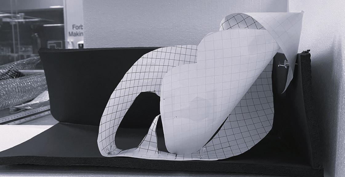
The next step was to use physical form finding with paper to create a gridshell form that could be developed into more realised ideas through mesh and digitisation. The assigned form of a cafe was explored through various abstracted forms, such as a croissant, espresso machine and latte art.
Elastic Gridshell Exploration Part 2: Form Exploration with Paper 6 Fiera
> Iterations from paper > > Progression diagram from abstraction to form > First spacial iteration from paper cutout > Second spacial iteration from paper cutout > Third spacial iteration from paper cutout > Final spacial iteration from paper cutout
The process of the espresso machine form began with researching images of drip. this was then sketched onto paper, with this form then segmented and cut out, with the decision to use the negative space of the espresso drip rather than the espresso drip itself, creating the two voids outlined previously. This cut out form with grid paper allowed for increased light play and curvature.
Espresso Sketch Negative Space Cut-out Spacial
Drip
Mindmap
FormFiera 7
> Spacial Abstractions for cafe interior > > “Hero shot” This exploration with paper resulted in four different forms, all creating unique space with unique light. On top of the precedents outlined on page 4, I was inspired by Melbournes laneways, that use an enclosed space to have a lively and vibrant cafe space. The brief required the gridshell to have a point of contact to a wall, with all of the iterations having connection to two walls rather than one. The result of this was spaces that resulted in less comfortable circulation and perhaps an over-enclosed space. As this design progressed, we would see spaces that only connected to a single wall that had free-flowing circulation through the space. Elastic Gridshell Exploration Part 2: Form Exploration with Paper > Cafe developmentspacial#1 > Cafe developmentspacial#2 > Cafe developmentspacial#3 > Cafe developmentspacial#4 8 Fiera
> Cafe developmentspacial#5 Fiera 9
> Development images of chicken wire meshexplorationThedesign then went though further refinement and realisation through chicken wire, simulating the mesh form of an elastic gridshell. After various initial failed attempts with the original form, the shape had to be adapted to remove aspects of the void. This was due to over bending from the wire that disallowed both synclastic and anticlastic curvature, with the form collapsing upon trying to achieve4 this. As a result, only the droplets from the initial form had been retained, however this was the key aspect of the void light play that I had intended to include. Elastic Gridshell Exploration Part 3: Chicken Wire Mesh Exploration > Chicken wire form plan > Chicken wire front elevation > Chicken wire side elevation 10 Fiera
In order to come to a final form, the most successful aspects of each group member’s design was implimented into one final form. The voids from my form, the bending moments from Christopher’s form and the segments of Afrah’s form were combined into one final gridshell, as seen below. Elastic Gridshell Exploration Part 3: Chicken Wire Mesh Exploration Abstraction from espresso drip Abstraction from Croissant Abstraction from Latte art > Images extracted from inital cafe abstractions \/ Final mesh model Fiera 11
The selected forms for this stage were a continuation of the forms created from the initial espresso form. The edges became more rigid, and the shape became more angular, allowing for better connections to the surface. Some iterations still used the void form, with this being my preffered iteration from this step.
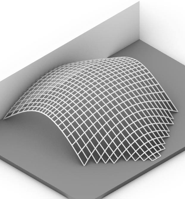
The next step was digital gridshell form-finding through a program called Grasshopper, a digital design software allowing for parametric modelling. Through a plug-in for Grasshopper called kangaroo, gridshell forms can be simulated from base shapes, calculating the height and bending moments of a physical elastic gridshell.
Elastic Gridshell Exploration Part 4: Form-Finding and Analysis > “Hero shot” of gridshell generated from Kangaroo form finding > > Various design iterations from form finding 12 Fiera
Iteration 1 Plan View Iteration 2 Plan View Iteration 3 Plan View Iteration 4 Plan View Iteration 1 Elevation View Iteration 2 Elevation View Iteration 3 Elevation View Iteration 4 Elevation View Fiera 13
A key aspect taken from the precedents was the edge beams along the connection points of the gridshell. These serve as seating for the cafe as well as structural supports for the gridshell, as well as edge bracing providing further support.
> Perspective hero shot of final elastic gridshell model > > Development images of elastic gridshell fabrication
Elastic Gridshell Exploration Part 5: Final Physical Model 14 Fiera
The final design was a result of further realisation and adaption of the previous models. The model itself was created in a “T” shape, a result of cutting and changing the previous forms. It still retains similarities to previous designs such as the previous kangaroo models with the overall layout, however accessibility of the cafe had to be considered as well as connection points.
Formation of Gridshell with cable ties Plan view Side elevation view Front elevation view Final form Fiera 15
> Form creation with Vacuum Forming machine > > Development of Pneumatic form
Pneumatic Shell Exploration Part 1: Form Finding 16 Fiera
The next step in the design journey was exploring Pneumatic shells. My assigned brief was a “stage” design, with various considerations nessesary for this to be successful. I intended on having two different spaces within my stage, a backstage area, seating, and the stage itself being the bridging point between these spaces. Both of my base forms engaged with this, forming two “bow-tie” spaces with the stage being the pinching point. These forms, as seen on page 17, were laser cut on MDF and then formed with the Vacuum Forming machine to inflate plastic through the cutout form. The resulting forms successfully fit the brief of a stage, however then had to be analysed in order to understand the realism of such a form.
Laser-cut cutout of form Inflated plan view Inflated plan view Side Elevation Side ElevationLaser-cut cutout of form Fiera 17
> External view of iteration #1 > > External view of iteration #! > > > External view of elevation #3 Section of pneumatic form iteration #1 Section of pneumatic form iteration #2 18 Fiera
Fiera 19
The Pneumatic Shell stage form created then had to be digitally analysed in a grasshopper plugin called Karamba. The plug in measures the structural performance of a form by having a number of inputs, being material, material cross section height (thickness) and input surface, among other commands. The result is a displacement scale, that identifies where the form is weak, identifying how far the material is displaced by a force, in this instance being gravity.
Maximum Displacement: 0.16318 (1.63cm) Material: Concrete C30/37 Material Thickness: 20cm Height: 4.95mm Pneumatic Shell Exploration Part 3: Karamba Analysis 20 Fiera 1.1.0.0e+001.7e-33.40e-35.10e-36.5e-38.5e-0302e-021.19e-0236e-021.7e-02 Karamba Model - First Iteration
Both forms are relatively successful with low displacement results, however it is clear where the form is strained the most. The points where multiple triangular subdivisions meet tend to be under a lot of stress, and these are found at the apex of any curve on the form. These must either be braced or avoided.
Maximum Displacement: 0.011774m (1.1cm) Material: Concrete C30/37 Material Thickness: 20cm Height: 4.4m Fiera 21 9.7.0.0e+001.18e-032.36e-033.54e-034.72e-035.9e-0308e-038.26e-0344e-021.18e-02 Karamba Model - Second Iteration
Case Study: Fiera Milano Part 1: Precedent Journal 22 Fiera Fiera Milano Full
> Photograph of Fiera Milano Full volcano Fiera Milano is an unconventional grid shell situated in Milan, Italy. It is a perfect case study for the exploration of gridshell structures due to the approach of several different construction methods to realise the design. The gridshell is consists of a raised peak (Logo) and several full and half valleys, referred to as volcanos and half volcanos, connected through flat quadrangular meshes that span approximately 1300 meters. The construction of the flat portions of Fiera Milano are constructed from 240mm steel bars, connected through four-pronged nodes, resulting in a quadrangular grid. These nodes are supported by “tree columns” at intervals of 16.2 meters longitudinally and 13.5 meters transversally. The tree nodes expand out to 4 outward branches, supporting 4 nodes. Volcano
Selected portion of Fiera Milano segmented for modelling Fiera 23 Plan view of Fiera Milano Triangular subdivisions Fiera Milano Full Volcano Fiera Milano Half Volcano
The half volcanos are constructed alternatively to allow for the unconventional angles required to realise the concept. The design is far too warped to be able to support quad mesh, so the mesh becomes triangulated. The result of this is the addition of members that run diagonal to the quadrangular meshes longitudinally. In addition to this, transverse diagonal members are added to each quad mesh, making connection to the ground.
Longitudonal members, diagonal to quadrangular mesh (Schlaich Schober)
Final Form (Schlaich Schober)
24 Fiera
Full volcano pentagons due to mesh alteration
Pentagonal Mesh
The full volcanoes become increasingly complicated, with the addition of spiralling bars. The result of this extra member is the forced introduction of a 5-pronged node, creating pentagonal mesh at these intersections in order to allow for seamless mesh. Bars arranged in a radial pattern subdivide and triangulate this mesh for fluidity.
Addition of transverse members (Schlaich Schober)
Yan)
Initial Render (Hao
Model
<<
Case Study: Fiera Milano Part 2:
The initial model was created on Rhinoceros 7, a digital design software. The form was designed using a method called SubD, which subdivides forms and averages the curvature between subdivisions, allowing for smooth and pliable curvature in a form. This approach was then referenced into Grasshopper, which created the members specified in the research stage, including the increased subdivisions within the volcano and half volcano forms. This however proved incredibly difficult to achive inside the volcanoes themselves, due to projection problems in the form. The result of this was subdivisions that were far too long, with real life subdivisions in the Fiera Milano never exceeding 3 metres. Many of these subdivisions were upwards of 5 meters. Initial Digital -
Fiera 25
The
were
Part 2: Initial Digital Model ManuallyrhinoconstructedsubD Recreated surface with diagonal grid Curve that marks out the area with bracing Surface with designed bracing area Cylindrical Joints Manuallycolumnsmodeled Mesh for glass panels Final model Steel frames Surface of simple diagonal steel frame Surface of simple steel frames with bracing Weaverbird midedge subdivision Dispatch using points in curve relationship (Through reconstruction) Get edge curves VerticescylinderbasedPipeBake 26 Fiera Initial Half Volcano Form (Hao Yan) Progression (Hao Yan)
Fiera
initial
We
The model was created on Rhinoceros 7, created through SubD, allowing for forms to fluidly be transformed through subdivisions. were new to this tool, resulting in geometry in the volcanos and half volcanos that did not follow the plan outlined in the reference document. The rest of the form, being the vela-roof and the platforms between were generated well from SubD, with touchups in grasshopper to formulate the bars and the panels within the roof. International Journal of Space Structures was paramount to recreating this design, with Schlaich Schober’s writings indicating how intricate aspects of the Milano constructed.
Fiera 27 Failed Karamba Analysis befor additional support points were added Improved Karamba Analysis
While some subdivisions generated horizontally rather than vertically, these could be swapped and the geometry could properly form.
After the inital analysis and feedback session, it was clear that the geometry of the volcano and half volcano had to be increasingly realistic, especially going forward into Afterfabrication.daysof deliberation, it was found that the method of creating the half volcano outlined in the Schlaich Schober’s file was not the most efficient method of finding the curve geometry. Rather, the only way to make it work was to add the subdivisions directly in Rhinoceros, creating more geometry subdivisions, rather then extending the default amount of subdivisions in the half volcano. This was also efficient in the full fulcano, The document states that the helix form is key, thus by adding a helix subdivision on the SubD, the geometry properly generated.
Case Milano Digital Model
Cleaned up geometry, final half volcano form
Part 3: Final
Form after addition of transverse members in grasshopper
28 Fiera
Initial form after increasing subdivisions, creating longitudonal members
Study: Fiera
Final full volcano form after cleaning up geometry
Fiera 29 Final Elevation with fixed volcano geometry Final Plan with fixed volcano geometry
Case Study: Fiera Milano Part 5: Physical Model Creation 30 Fiera
>
Hero shot of physical model
The final physical model of the Fiera Milano was created from a combination of 1mm mountboard, along with 3D printed sections. The inital step was to segment the sections that would be laser cut, and segment the sections that were to be 3D printed. The next step was to run a script that measured the intersections between the diagonal curves in the digital model, which then generated notches in the linework for laser cut fabrication. Spaces that were not laser cut were sent to the 3D printers, which were the full volcano, half volcano and the trees that were to hold the structure up.
The strips were then sent to the laser cutters in order to be assembled. The X and Y axis of strips were separated out and placed in their nessesary order, however this came with great difficulty to complete successfully. Eventually, the laser cut sections of the Vela Roof were assembled, with diagonal bracing being required to reduce bending in the members. The bracing profiles had to be separately fabricated, and placed alongside the voids for the 3D printed volcanos. of volcano structures Laser constructioncut Transversebracing
Fiera 31 3D Printing
ModelRhino Laser-cutstrips
Case Study: Milano
Part 5: Physical Model Creation
Fiera
Finally, the model was braced externally, supporting the form from both lateral and transverse forces. By gluing each intersection between the bracing and the vela-roof, each strip was glued to the edge beam (bracing) thus supported. The form was then spray painted white for consistency, then finally, the 3D printed half volcano and full volcano could be inserted into the structure.
Fiera Milano: Final Model 32 Fiera bracingLateral paintingSpray Assembly Completion
Fiera 33 Side elevation of final Fiera Milano model
34 Fiera Final form of 3D printed full volcano Final form of 3D printed half volcano
Fiera 35 Plan view of Fiera Milano Model Elevation view of Fiera Milano model
Afrah, 2022. Mesh Model Sketch. [image] Christopher Andonioff, 2022. Mesh Model Sketch. [image] Frei Otto, 1975. Mannheim Multihalle [image] Available at: Haoconstruction-and-inspiration-detail-book-report-06-02-2015/https://www.designboom.com/architecture/frei-otto-a-life-of-research-[Accessed25thJuly2022].Yan,2022. Model Renders [image] Hao Yan, 2022. Progression Diagram. [image] Institute for Advanced Architecture, 2015. Acts on Tracks. [image] Available at: <https://www.iaacblog.com/programs/acts-ontracks/> [Accessed 25 July 2022]. Schober, Schlaich. 2005. "New Trade Fair In Milan". International Journal Of Space Structures 20 (1): 1-14. Shigeru Ban, 2002. Japan Pavillion. [image] Available at: https://clarewashington.wordpress.com/2012/12/10/shigeru-banbuilding-with-paper-japan-pavilion-expo-2000/ [Accessed 25th July 2022]. Bibliography


