5 minute read
Refurbishment of the shut-off flaps

from zek HYDRO 2022
by zek Magazin

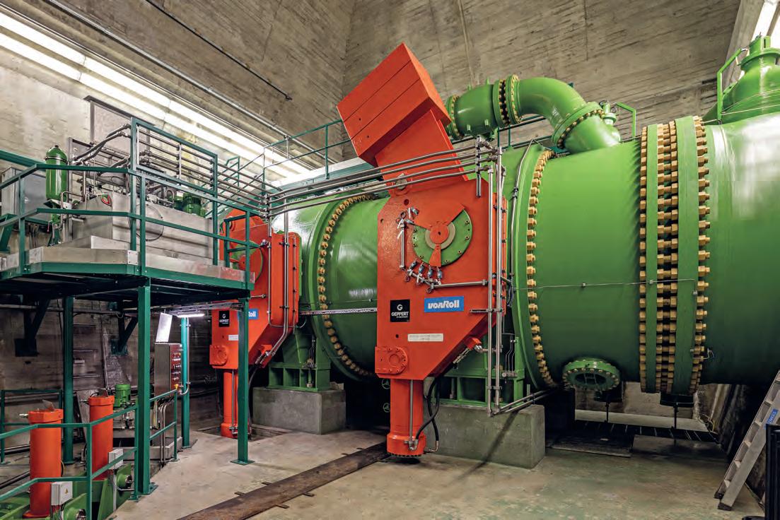
Butterfly valves after completion of maintenance work. Geppert needed around 6 months for the refurbishment of the valve components.
photo credits: Geppert
VALVE RENOVATION GUARANTEES HEADRACE SAFETY AT KÜHTAI PUMPED-STORAGE HYDROPOWER PLANT
The mighty DN3500 valves were in operation in the headrace at the Kühtai pumped-storage hydropower plant for around 40 years. When the Tyrolian plant operator TIWAG lowered the level of the adjoining reservoir in the late autumn of 2019, it provided a perfect opportunity for a fundamental maintenance sweep of the headrace. Particular attention was paid to restoration of the two PN25 pressure category butterfly valves. The work was conducted by Geppert, the Tyrolian hydropower specialists. The contract posed several technical challenges and took around half a year to complete.
The Längental and Finstertal reservoirs form the hydraulic basis for the Kühtai pumped-storage hydropower plant, part of the Sellrain-Silz group under the auspices of Tiroler Wasserkraft AG (TIWAG). The reservoirs are connected via a DN3500 pipeline. Safety is ensured along the works water route by two mighty butterfly valves installed in a cavern-like service chamber at over 2,150 metres above sea level, directly under the Finstertal reservoir dam. The valve service chamber can only be accessed via a 300-m tunnel in the mountain. At the beginning of 2020 there was an ideal opportunity to subject the valves of the works water pipeline to a comprehensive programme of restoration. Hugo Götsch, the TIWAG project manager, commented on the initial situation: “At first there were no external signs of wear or damage to the valves, but when the decision was made to empty the reservoir, we seized the opportunity to inspect these essential shut-off devices – and repair them if required. Fortunately, the drawdown of a reservoir is a fairly rare occurrence.” Geppert Hydropower, the Tyrolian hydropower allrounders, were charged with the refurbishment of the two valves, the bottom outlet infrastructure, the dead space draining system and of the regulating gates.
COMPREHENSIVE PREPARATIONS Before deinstallation could commence in the valve service chamber there were several issues in need of attention, as Markus Klotz of Geppert Hydropower remarks: “Along with the necessity of scheduling work, equipping the site, organising assembly teams and coordinating with the various subcontractors, it was first necessary to plan dismantling work. This involved a carefully-sequenced task framework. Moreover, we needed to agree points of contact with the TIWAG team, and establish in advance how much leakage water could be expected from the bottom outlet. This was important because a large degree of leakage would have necessitated a different sitework plan, and it wouldn’t have been possible to remove both valves simultaneously. We would have had to remove them one after the other.” Activities ultimately commenced in January 2020 when Geppert began dismantling the original valves. This was no easy task, since each of the 3.5-m valves weighed around 60 tons. Luckily the assembly team had access to
graphics: Tiwag Dismantling the upstream side valve DN3500.
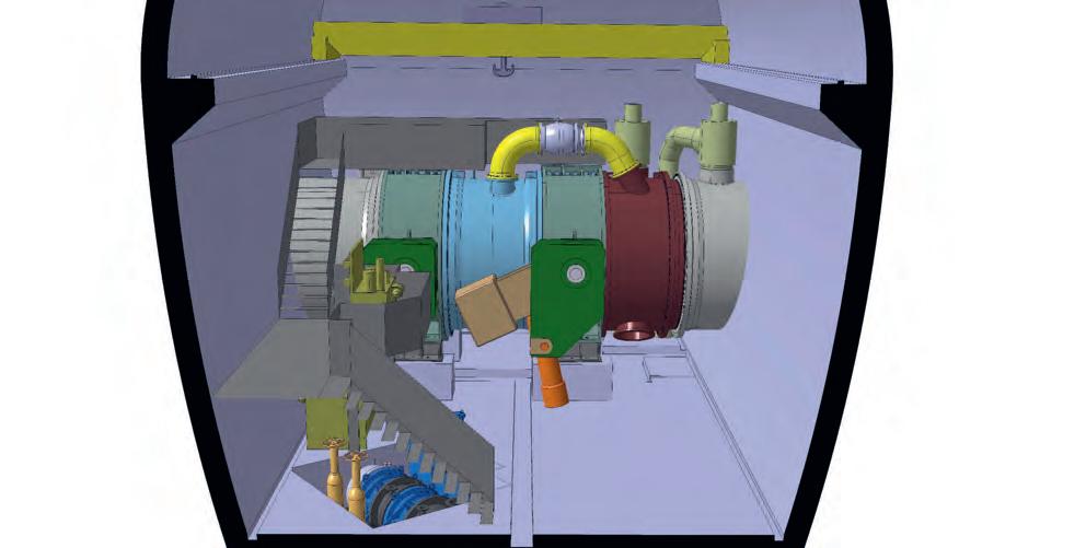
3D visualisation of the valve service chamber
the original plant installation plans from 1979. This allowed dismantling to be conducted as an exact reversal of the original installation procedure. Nevertheless, both the dismantling work, and subsequent transportation of the individual components out of the access tunnel, involved considerable technical challenges.
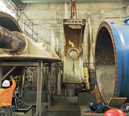
CHALLENGING DISMANTLING PROCESS Geppert’s Markus Klotz explained the main steps in the dismantling process: “First, the dismantling team had to remove all attachments, such as the bypass pipes, measuring conduits and supply channels, the parts of the drive systems on both sides, hydraulic cylinders, drive levers and counterweights. Subsequently we loosened the flanges of the dismantling joint to provide an axial gap of around 12mm. This enabled us to move the downstream side valve on a purpose-built track towards that gap and to lift the intermediate pipe out of its position. Having relieved the disc’s weight with assembly supporters, the technicians were able to remove the first half of the housing sideways. Subsequently, the disc was removed from the remaining half of the housing.” Once dismantled and removed, the components were prepared for transportation. The procedure was performed in the same way for the dismantling of the upstream side valve.
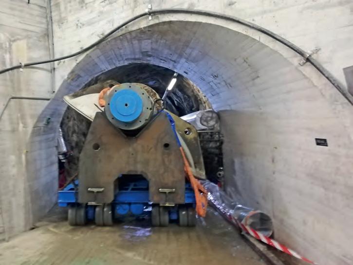
HANDLING HEAVY WEIGHTS TIWAG’s overhead hall crane had already been upgraded to a maximum capacity of 30 tons ahead of transportation to enable it to lift the 25-ton valve discs and the trunnions. Transporting the items along the access tunnel was a first test for the viability of the operation. Due to the cramped conditions, as soon as each individual component had been removed from the overall set-up it was transported out through the tunnel. “Since the system was originally built, the size of the tunnel cross-section had shrunk by the height of the road. As a result, components that couldn’t be disassembled any further, like the intermediate pipe and the dismantling joint, had to remain in the valve chamber to be refurbished there. For this reason, special tunnel ventilation had to be installed for cor- rosion protection work” Markus Klotz explained. He emphasised the need for extremely detailed planning regarding transportation of the valve parts out of the tunnel. This required very precise cross-sectional measurements of each section of the uncladded tunnel, the aim being to facilitate transportation of components, such as the housing parts and the valve discs, out through the tunnel using a manoeuvrable heavy-duty trailer. Klotz continues: “We developed a support frame to transport the valve discs with the trunnions attached. So the adapted heavy-duty trailer was able to manoeuvre its bulky load along the tunnel, and then a special heavy-load transport convoy to the factory in the town of Hall, without exceeding an effective width of 3 metres.” On top of the technical difficulties encountered in the cramped valve service chamber, Geppert’s team of technicians were also confronted with the challenges of an Alpine winter. Hugo Götsch outlined the scenario: “In January 2020 it was mid-winter up there at 2,000 metres above sea level, and the snow
Discs and transport frame being manoeuvred in the access tunnel on a heavy-duty trailer.
Foto:Wien Energie
photo credits: Geppert photo credits: Geppert


