CLIMACTIVE
Architectural Envelope for Passive Environmental Control
Juan E Subercaseaux Garcia de la Huerta Emergent Technologies and Design Master in Architecture Architectural Association School of Architecture
Michael Weinstock, Michael Hensel, Achim Menges, Martin Hemberg
Acknowledgments
I want to thanks to my all family, above all to Juan Subercaseaux S. my father and Juan Garcia de la Huerta my grandfather for their unconditional support.
Also my gratitude to all my tutors for their guidance and enthusiasm with my project.
Finally many thanks to Nikolaos Stathopoulos for his invaluable collaboration with the computer fluid dynamics simulations.
Index Chapter zero, Introduction 004 Abstract 005 Aim and scope 006 Design path 007 Chapter one, Controlled approach to pneumatic design 008 Background 009 Material system 015 Analog experiments Mechanics 017 Geometry 026 Geometry + mechanics 031 Partial conclusion 043 Chapter two, Material system contextualization with design strategies 044 References Hall 8 Expo 2000 Hanover 045 Eden Project 046 Retractable roof at Rothembaun 047 Parametric day light filter 048 Performance envelope 049 Fluid dynamics 050 Environmental context Climatic zones 051 About the location and the program 053 Parametric design engines Global to local 054 Local to global 060 Melting of scales 064 Environment cast in building Wind flow simulations Geometry preparation for CFD 066 Mappings 069 Light mapping 075 Watering system 0 atering 078 Chapter three, genotype make up, observed phenotype 081 Building genotype Shape and tessellation 082 Light permeability 083 Air permeability 084 Water collection zones 085 Light and pressure systems negotiation 086 Building phenotype Digital model 087 Analog model 091 Light system observations 095 Ventilation settings observations 100 Pneumatic system observations 101 Programmatic lay out 102 Chapter four, closure 104 Conclusions 105 Further development 106 Bibliography 107 003
004
Chapter zero Introduction

General:
Like the structures present in nature that have the ability of mutation in response to changing environments, the dissertation project is mainly aimed to design and construct a dynamic/kinetic system. This is a climatic envelope that reacts to the environment in which it is placed, keeping its structural capability, with characteristics to make it perform as a passive reversible system, operated by external changes.
Research paths:
The work rests in two symbiotic paths of investigation: Physical and digital models.
Physical.
There are two main families of physical models, one is developed to investigate mechanic properties such us pneumatic forces and articulations and the other informs geometry principles such us advanced construction processes and proliferation strategies.
Digital.
Information from analog models is extrapolated into the digital realm, where several test are run in order to corroborate information. The output from this process is strategically layered and combined in order to define the final physical geometry.
Design entities:
The system is defined by the creation of genetic design tools or “Parametric engines”. There are two main parametric engines, one on a macro scale and another on a micro scale. The third element involved in the design process or geometric definition is the environment where the system is placed. From there are extracted: Sun light exposure, wind forces, temperature and water precipitations.
The two design entities plus the information extracted from the environment are combined in a strategic way in order to achieve a different phenotypes from one constant genetic input.
Structure:
From a composition point of view, the project is a grid shell without secondary structural elements. Structure and skin are combined together in one arched organization with aerodynamic features. This shell is decomposed in a non regular triangular tessellation.
The triangular grid is composed of components that have the same structural role.
Performance:
The project is driven towards the definition of a “Climatic Envelope”. The global output is layered and populated in a specific manner. The range of components and their location on the surface is the product of the hierarchical association derived from: Light, Air and Water
The result is an organization that achieves a complex emergent behavior trough simple and direct reactions to external stimulations. Therefore the system behaves as a passive climatic regulator, controlling sun light exposure, permeability, air movement and temperature.
Abstract C_0.1
005
Pneumatic system early model
On the first hand, the aim of the dissertation project is the implementation of a pneumatic material system that is able to have the lifespan and the consistency required to be incorporated in the architectural scale and programs. On the other hand, the thesis aims the design of a structure, with characteristics to make it perform as a passive, dynamic and reversible system, operated by external changes in the environment where it is placed. This means that the system needs to react itself, without the use of external mechanic devices such us engines, sensors or operators.
Generally speaking, pneumatic systems require non elastic membranes or components in order to be stable from a structural point of view. In parallel dynamics or kinetic systems generally have at least one elastic or flexible component that allows the reorganization of the geometrical configuration of the structure. Since the structure is aimed to be dynamic and stable at the same time, one of the key stones of the thesis is the definition, implementation and corroboration of a dynamic organization operated by smart devices, without compromising the overall stability of the structure and its appropriate lifespan in order to insert the project into the architectural field.
From a strategic point of view, the thesis aims to design not only a building but also a process that can be repeated in different circumstances and environments. Thus the design strategy is the genotype and the final geometrical output is the phenotype, or sample, that allows us to explain and corroborate the design process (genotype). At the same time during the evolution of the thesis and the definition of the elements that will conform the structure, it is very important to consider that the project should be able to be constructed, thus the thesis involves the creation of an efficient process of production, transportation and assembling of the structure. Therefore the structural system is inserted within the parameters of production techniques available, and on the other hand it is a product that can be developed and placed in different locations according to the circumstances.
Aim and Scope
C_0.2
006
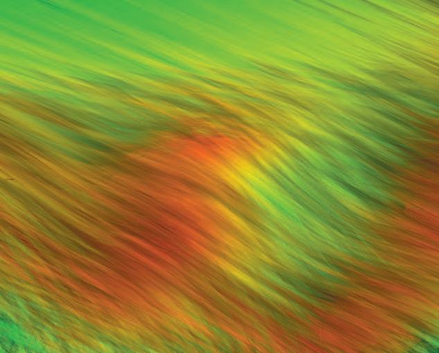
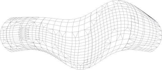
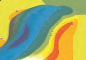
Computer fluid dynamic image of winds flow simulation
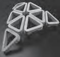
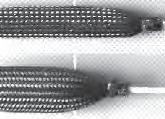




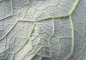

Resume of thesis evolution and design definition
This chart is an introductory map to navigate through the thesis; here are high lightened the most important concepts, experiments and facts that were conducing the development of the study.
1_Intial research in nature and early experiments defined the framework to develop a new material system, this new technique suggested then the theoretical research for architectural references and applications.
2_Aiming to insert this body of work into a real environment, a site and a program are proposed for the building, together with the introduction of fluid dynamics principles.
3_Later on, the combination of the material system together with the environmental research will lead to the definition of the design tools needed to create an specific shape tuned with the requirements.
4_Then this shape is taken into a predefined set of performance analysis, from were some very specific information if gained. This information is combined strategically into a “genotype for the building”.
5_From the genotype procedure is extracted a sample building. This particular “phenotype” is again rigorously observed. From those observations an operational and programmatic lay out is set for the building.
6_As a closure, the final product –building- allows stating several conclusions in relation to the building and the design process, on the other hand raises some questions and preserve open some issues for further research.
Design path
C_0.3
Fluid dynamics, Environment Parametric engines, Global to local, Local to global, Melting of scales Environment cast in building envelope , Genotype set Phenotype observations C F Closure 007
Background, Nature, Pneumatics Research, Models, Theory Context,
Chapter one
Controlled approach to pneumatic design
008
Models in nature applied to the system
Turgor pressure
Turgor pressure:
Is the pressure produced by a solution in a space that is enclosed by differentially permeable membrane. When a cell is in a hypotonic environment, water flows across the cell membrane into the cell causing it to expand. The membrane restricts the expansion, which causes an increase in pressure. The resulting pressure is called Turgor.
Definition extracted from: www.wikipedia.org
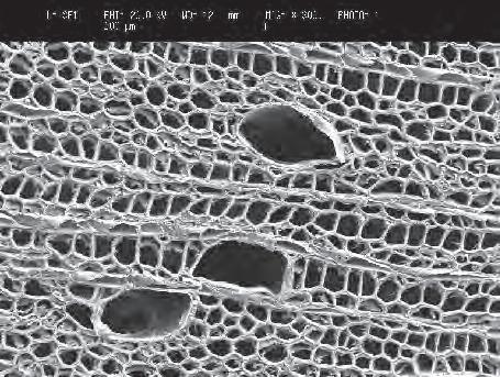
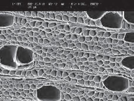
During the biomimetics seminar course, we where introduced to several strategies used by plants to reproduce, grow and change their geometrical configuration. From there the concept of turgor pressure was extracted as an input to develop a material system.
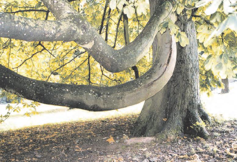
As all mechanisms of plant movement, the orientation of branches depend on four design elements:
-Interacting cells (shape, dimensions, organization)
-Fibrous cell walls (cellulose) layers, orientation
-Turgor pressure (active movement)
-Sources of energy
The Turgor pressure principle can be defined as a pneumatic strategy that plants use to keep the rigidity and to change the direction of the growth of their stems or branches. This is achieved by changing the inner pressure of the cells organized in the different layers of the structure. This is to produce a bending behaviour and this way prove to be a stable pneumatic system.
The stability of the re-configuration is achieved thanks to the amount of cells that are working together, thus is can be named as emergent behaviour since the final output is operated by a hierarchical organization where each individual component is informed to behave in a particular manner, therefore the overall system re-configures itself.
In the context of the investigation undertaken, it is interesting to look into this principle because of the collective organization of cells involved in the reorganization and at the same time the pneumatic principle behind the activation of the cellular components.
“The stability of the re-configuration is achieved thanks to the amount of cells that are working together, thus is can be named as emergent behaviour”
Background
Example of a stiff element (branch of a three) curved by changes of Turgor pressure in inner cells.
C_1.1 009
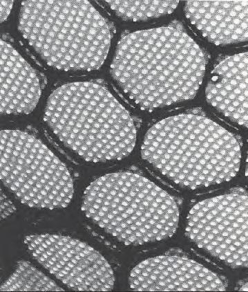
Microscopic view of two stages of cellular organization hypotonic (cell interior contains a lower concentration of water than its exterior) and isotonic (when is in equilibrium to the concentration of water in the environment)
Background
Models in nature applied to the system
Tessellation strategies in diatoms
In order to research tesselation strategies, this part of the thesis focuses on the investigation of diatoms.
Tessellation:
Tessellation is a collection of figures that will fill a plane, surface or space with no overlaps and no gaps. In Latin, tessella was a small cubical piece os clay, stone or glass used to make mosaics. The word “tessella” means “small square”
Diatoms:
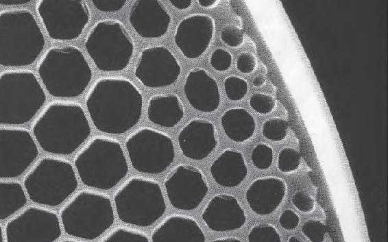
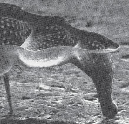
Diatoms are a major group of eukariotic algae, and are one of the most common types of phytoplancton. Most diatoms are unicellular, although some form chains or simple colonies. A characteristic feature of the diatoms cells is that they are encased within a unique cell wall made of cilicate. These walls show a wide diversity in form, some quite beautiful and ornate.
Definitions extracted from: www.wikipedia.org
Diatoms are conformed by silica deposit in the shell This together with the morphology of diatoms is largely controlled by a pre-pattern. Thus the basic question with regard to the formation of the silica shell ia a question of definition of the pre-pattern.
Assuming this, the questions that arise are:
To what extend it is genetically determined?
To what extend it is determined by the environment?
To what extend it is determined by characteristics immanent in the system?
The fact that indeed all the three factors are involved is shown by a simple consideration. A genetic determination results from the fact that the triggering of silicification is controlled by the nucleus of the cell and that general classification of species is based on the shell pattern. There is an environmental factor since the varying conditions result in variations in the shell design. Finally, the characteristics immanent in the system can be the result of structural or material aspects, such as the initially evolutionarily trend directed towards increasing silica solidification followed by a trend to safe material. The fact that the shell is formed according to a plan determined from the beginning, makes an interesting analogy between the diatoms shells and man-made structures. In relation to this, the project developed in this thesis is approached in the same manner by the definition of a genetic input affected by the environment and informed by characteristics immanent to the system. Also it is important to address that the formation process of diatoms is controlled by pneumatic principles, since they form in most cases around bubbles or “arolar vesicles”. These vesicles owing to the tensile stress and inner pressure are compressed on the surface of the cell and thereby packed more densely.
Thanks to the formation process described above, diatoms achieve some amazingly specific and differentiated tessellation strategies according to genetic input, environmental variations and material organization. This together with the fact that diatoms are shell structures, makes them a very important topic to address and research in the context of the thesis.
“The fact that the shell is formed according to a plan determined from the beginning, makes an interesting analogy between the diatoms shells and man-made structures”
different sizes of cells in a diatom shell in relation with the location on the structure.
Hierarchical differentiation of two scales of tessellation in the same diatom shell
010
Shell building formation between prestressed braces. Example os complex shape achieved by a diatom.
Background
Input of pneumatic models and digital experimentation
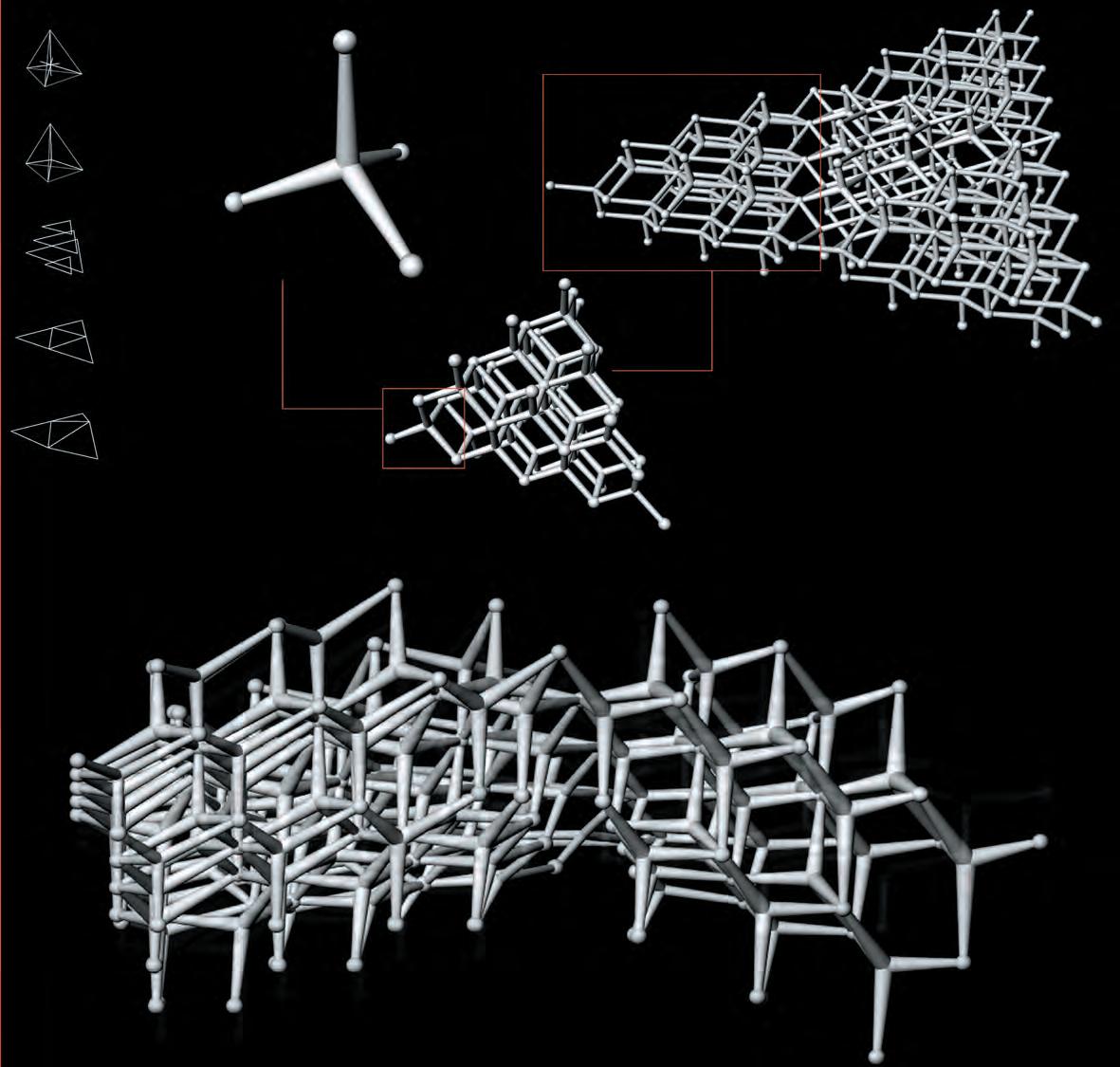
Tridimensional packing system parametric model
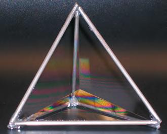
On parallel with the research of pneumatics principles and tessellation strategies in nature , some initial digital models where created taking as an input the observation of the most geometrically economic but also very unstable pneumatic material system as it is with soap film models. This early experiment is observed as an example of 3d tessellation and also as a particular geometrical configuration that uses pneumatic principles of space partition and organization.
The experiment is focused in the identification of centroidal Voronoi tessellation and boundary optimization logics exhibited in close-packing systems. An analogue model was fabricated; achieved by submerging a platonic tetrahedral frame into soap film solution bath. Geometric logics were identified, and based on the geometric fundamentals of Plateau’s laws extended into three dimensions, where three relaxed soap bubbles can only meet at an angle of exactly 109° 28’ 16”, a four segment tetrahedral dihedral angle component was digitally translated.
The second step was to nest the component inside a layered triangular organization of 38 features, generating a parametrically deformable triangular tile with regular pentagonal dodecahedra (12-sided) interior cellular partitions. This tile was a periodically distributed into a larger equilateral configuration with a total population of 152 nested component features. As an established parametric system, a procedure of external modification was introduced. With the isolated manipulation of one single input point, a re-configuration of 114 primary components resulted; maintaining the rigid cellular partition coherence while relocating the respected individual centroids.
“With the isolated manipulation of one single input point, a re-configuration of 114 primary components resulted”
Analog model geometrical input. Three relaxed soap bubbles into a four sided platonic tetrahedral
011
Proliferation logic and nesting procedure in GC of component extracted from analog model
Background
Input of pneumatic models and digital experimentation.
Sizes and boundaries of pneumatic cells affected by displacement of centroids in a “Weire Phelan Foam cluster”.
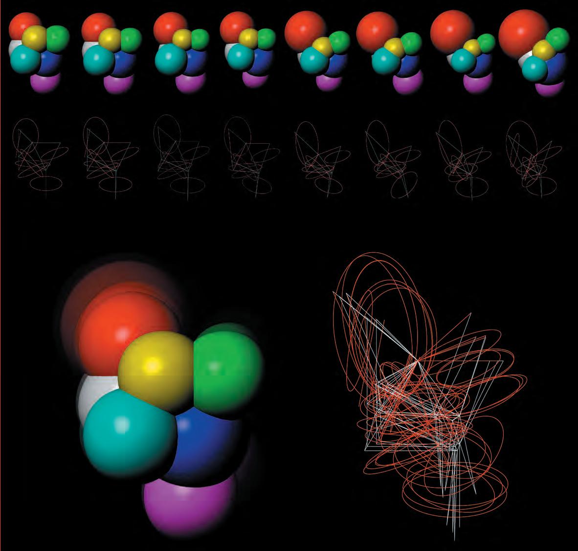
As a continuation of the previous experiment, this digital procedure is based also on the observation of pneumatic soap film organizations. This model aims towards the research of boundary relations between neighboring pneumatic cells.
The experiment is focused on the observation of an isolated cluster of eight cells arranged initially in a “ Weire-Phelan Foam Structure” pattern, (two irregular pentagonal dodecahedra (12-sided) six tetrakaidecahedra (14sided)). This organization has the particularity of being the most economical geometrical deduction of a close packing system. The geometric logics of construction and boundary relations between the cells where observed and extracted into a parametric model.
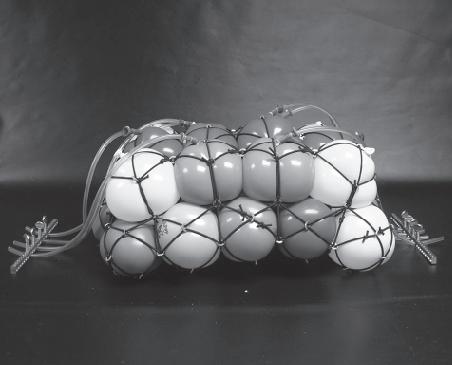
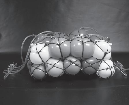
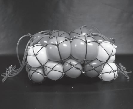
The sequence of captures, are different instances of the process of threedimensional displacement of the centroids of the cells. Each new arrangement affects the position of the cell informed and, on the other hand, stimulates the neighboring ones, readjusting their volume in order to remain in a state of collective equilibrium, according to the logics of foam structures.
With this model two different outputs where observed, firstly the relation between the volumes of the components, and secondly the displacement and spatial reorganization of the borders between the cells.
This experiment, together with the previous one, where both were based on soap film observations. Despite the fact that different logics where extracted in each case, in both of them the principles observed and taken into the digital realm, where very interesting. On the other hand the material system used (soap film) proved to be not stable enough to develop further analog models where mechanics and physics tests are intended to run.
“Each new arrangement affects the position of the cell informed and, on the other hand, stimulates the neighboring ones, readjusting their volume in order to remain in a state of collective equilibrium”
012
Sequence of the reorganization of soap film cluster model activated trough changes in digital real (Generative Components parametric model)

Background
Input of pneumatic models
Progressive reduction of pneumatic devices.
Form finding, tessellation arrangement
Pneumatic composite systems
Dynamic, pneumatic, hybrid systems
In the soap film experiments, and their posterior translation to the digital environment, three different material entities where observed and digitally analyzed. The air or pneumatic pressure, the segments described by lines or edges between cells and the surfaces described by soap films between these segments. Taking these three elements, different materials where explored with the aim for a pneumatic/kinetic material system but exploring more stables techniques.
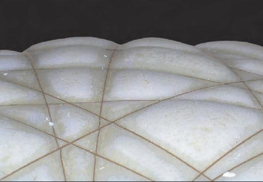
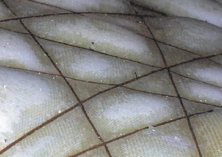
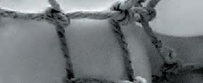
1_The first family of experiments were constructed with an elastic mesh fixed in a solid frame wrapped with nonelastic thread. Afterwards poliuretan expanding foam was injected, the expansion of the foam produced an increase in the volume and pressure of the model. The nonelastic threads sets the maximum of expansion defining an overall curved geometry (or dome). Due to the further expansion of the mesh between the nonelastic elements, another generation of secondary domes where formed, giving to the already overall stiffness of the shape another layer of secondary structure in accordance with the tessellation defined by the arrangement of the threads.
As a form finding process this experiment proves to be quite successful. The material entities involved in the structure were organized in a very efficient manner by the pneumatic force transmitted trough the expandable foam. On the low side however, the foam proves to be a very messy, and rather difficult material to control. And more importantly, the structure could not perform any readjustment once it sets, thus it was non-kinetic. The development of this material system was stopped at this point, but was the first step of the experiments to come.
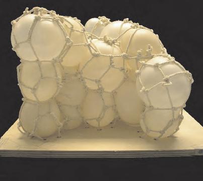
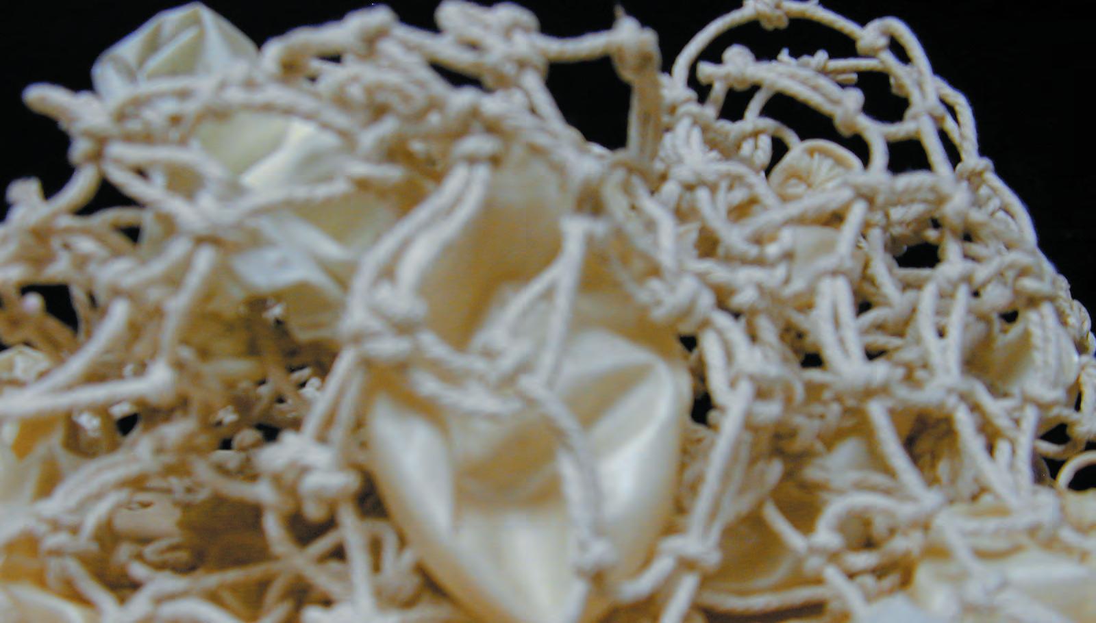
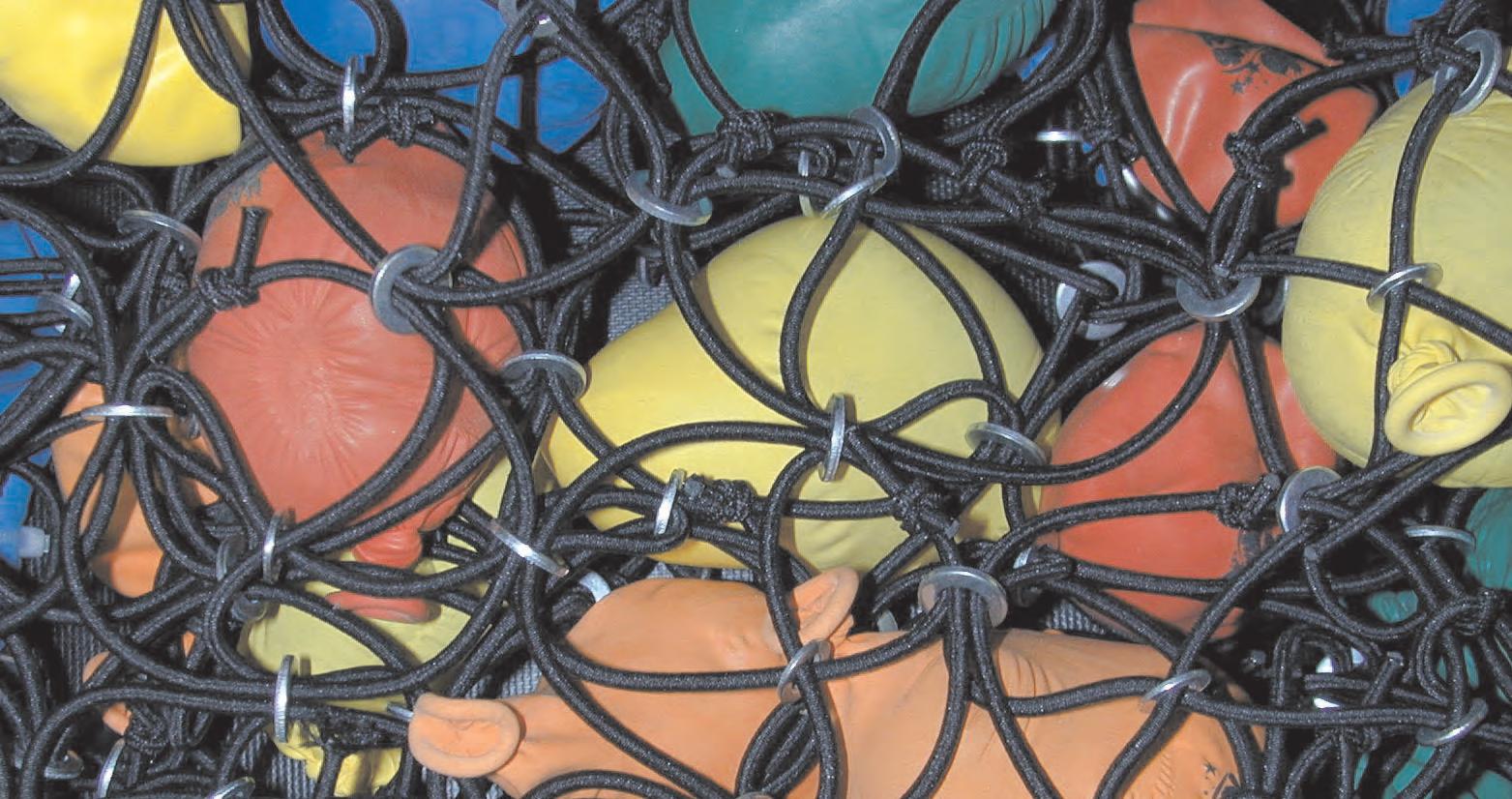
2_Another similar set of experiments was developed using balloons, non elastic thread and air as a pneumatic device. The major difference of this experiment to previous ones is that the threads were knotted together as a three dimensional net so the form finding process was to some extent affected by it. On the other hand instead of having one big body of pneumatic volume this experiment had several cells conformed by balloons. This model proved to be quite successful as a first attempt to move from composite to hybrid structures where the elements involved in the shape are shearing structural efforts and defining the geometry between the interactions of their material properties. However, this experiment was not achieving the ability of the soap film to reorganize itself to changing boundary conditions or any other external input.
3_With this in mind the third family of experiments were developed using an elastic thread and a system of valves in order to be able of change the pressure of the balloons (cells) placed in a strategic manner. Actually this set of experiments was directly extracted from the “Turgor pressure” strategy used by plants to reorganize themselves.
The balloons where arranged in two layers and attached by elastic threads in an economical 3d space partition. As the pressure was changed in one of the layers, the overall organization was able to change shape, which in this case was the curvature of the surface. This early experiment was very successful and became the starting point for development of the material system. Nevertheless there was a problem that was still unsolved........
1_Model from hybrid system module, pneumatic form finding tessellation system, fabric, cotton cord, resin, expanding foam.
2_Composite pneumatic structure from module 5, packing system, cotton cord mesh + balloons + pressure.
013
3_Pneumatic dynamic hybrid system from module 5, contractible packing system, global curvature change trough many local manipulations.
Background
Input of pneumatic models
Instability of elastic pneumatic material systems
As it is shown in the pictures on the left, the life span of the pneumatic material system investigated in the last experiments, was quite short (one week with stable environmental conditions).
It is important to state that this condition is due to the kinetic performance aimed in the material system. In order to have a dynamic system combined with pneumatic devices, it is indispensable to use elastic elements in the structure, and in most cases, elastic membranes. As it has been proved in numerous experiments, pneumatic systems cannot support loads if there are elastic elements within the structure. Instead, if there are not elastic elements involved the pneumatic systems can carry considerable loads as it is evident in many structures, such us inflatable boats (Zodiac). On one hand the material system to be designed needs to have a sufficient life span in order to be inserted in standard architectural projects and on the other hand it needs the necessary structural stiffness to support its own weight and extra loads such as wind and water.
“As it has been proved in numerous experiments, pneumatic systems cannot support loads if there are elastic elements within the structure. Instead, if there are not elastic elements involved the pneumatic systems can carry considerable loads as it is evident in many structures”
014

Material System Concept Flexible tessellation + Strategic location of elastic devices + Environmental input.
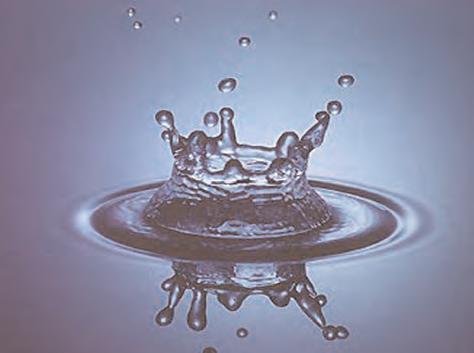
The strategy to develop the material system is composed of two main elements, flexible tessellation and strategically located pneumatic devices. The concept is driven by the reduction in size of the pneumatic devices, thus it gains in stability. At the same time the number of devices increases, so they are performing in a collective manner, shearing structural load and achieving global changes in the system by actions taken in local and regional scales. On the other hand the location of pneumatic devices play a major role in how the system will react to their stimulation.
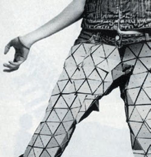
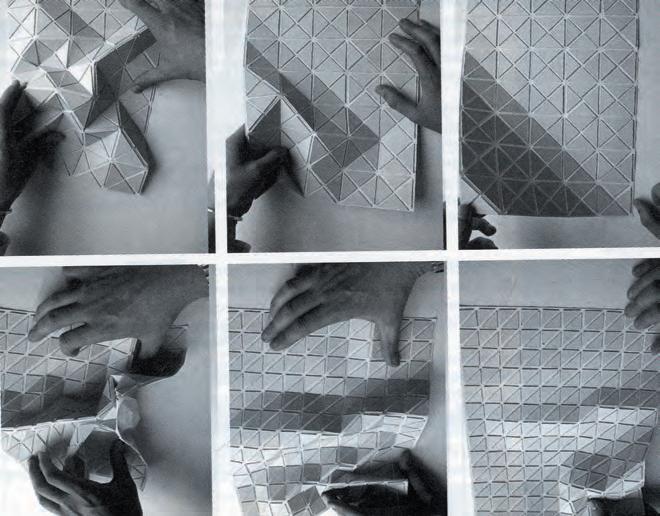
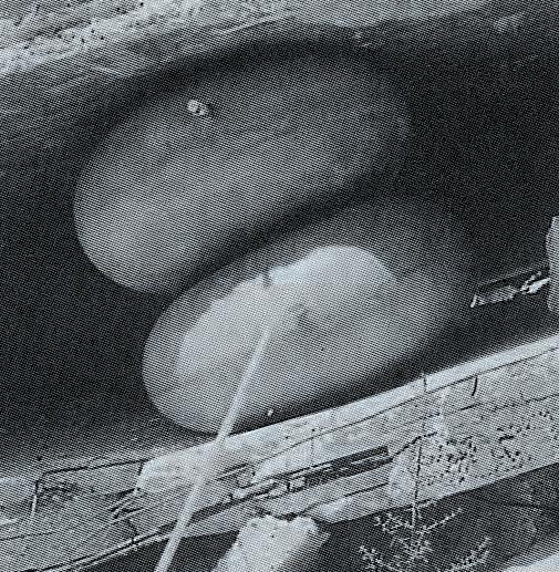
1_In the case of the tessellation the research starts with the investigation of triangular shapes. Since triangles are able to achieve the description of any shape or surface by planes without loosing the structural capacities of each component. On the other hand, when they are attached together in a collective configuration, the whole surface tends to be structurally instable because of the flexibility of the tessellation, this will have later an impor- later tant effect on how the individual “tessellas” will connect together
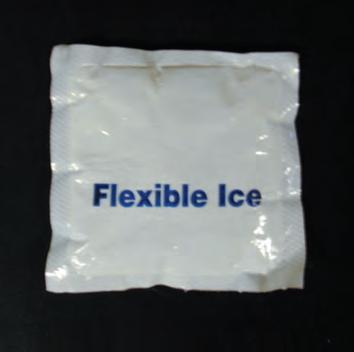
2 The pneumatic device used in the development of the material system is a powder that has the ability to swell water and release it only as vapor. This material is widely used in different industries, such as the food industry where it is know as “flexible ice” (there it is used for the preservation of food in dry environments). The scientific name of the powder is “CMC Gel” (carboxy_methyl_cellulose). In the context of the project this material is very interesting because of its pneumatic properties. When in contact with water the material expands keeping its stability and volume until it comes back to its initial configuration after releasing the water as vapor. Thus is a reversible pneumatic system it can carry a considerable amount of forces in relation to its volume. Finally the fact that it reacts with water makes it a very suitable pneumatic device in order to be operated by changes in the environment, like rain and hot weather.
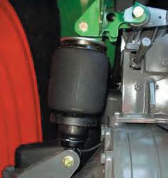
3_Taking as an example the suspension system in a car (in some cases a pneumatic system), the interrelation between pneumatic components and the steady ones are strategically located in order to achieve an specific performance. A car does not need to be entirely “loose”, flexible or pneumatic in order to be comfortable. Actually a car is a very sophisticated machine with incredible structural and dynamic capacities. One part of this complex structure is the suspension system, that is also reversible and is activated by changes in the topographical environment where the car is moving. In the following experiments the research is focused at the interrelation of “CMC Gel” pneumatic devices and solid cells or parts of the system. The aim is to define an instrumental way of connecting them in order to achieve a collective performance that can be related to the architectural scale and program.
“The concept is driven by the reduction in size of the pneumatic devices, thus it gains in stability. At the same time the number of devices increases, so they are performing in a collective manner, shearing structural load and achieving global changes in the system by actions taken in local and regional scales”
1 Examples of triangular tessellation surfaces and their ability to adjust to any shape
2 Small pillow of “flexible ice” CMC Gel, the stimulation agent (water), as a result pneumatic forces (in the case of the picture used to lift heavy loads).
C_1.2 015
3 The images are showing how isolated pneumatic devices can play a major role in highly complex and articulated systems, by the strategic location of them.
Specific
1 gr. raises 1 newton 1 newton = 100 grms.
1 liter contain 500 grms. of CMC Gel carboxy_methyl_cellulose
A volume of 10x10x10cm can raise up to 100 kgms.
Mechanic properties and scaled values
400cm. 800cc. 800kgms.
200cm. 200cc 200kgms
300cm. 450cc. 450kgms.
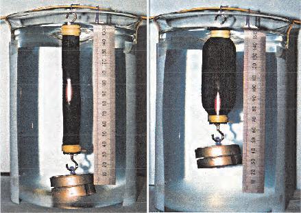
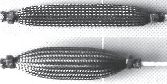
During the Biomimetics seminar course, we where introduced by George Jeronimidis to pneumatic muscles developed in the Biomimetics Department of Reading University. These muscles are constructed placing CMC Gel in the interior of a flexible pipe (TechFlex) made out of a bidirectional non-elastic mesh. This pipe is flexible and deformable. Nevertheless it deforms in a particular manner thanks to the directions of the fibres. Once the gel inside absorbs water, it increases in volume, and since the gel is contained in an enclosed environment the forces created by the expansion are transmitted to the pipe. As the pipe grows in diameters it get shorter in length, due to geometrical arrangement in the fibres of the pipe and their non-elasticity. The system stabilizes when the maximum possible volume is achieved. As a result the muscles provide a pulling force. Afterwards, as the water is released by evaporation the muscles returns to their relaxed configuration.
This experiment was then discussed after a visit to Reading University, and the concept was taken as the starting point for developing the technique further and introducing it into a project with architectural applications. After measuring the forces transmitted by the muscles, the values where scaled and estimated in relation to the size of the mechanic pneumatic devices. As a result, some interesting facts where extracted. The first one being, that the forces are directly related with the volumes of the muscles, the bigger the muscles the higher the forces. On the other hand if the muscles are thinner, the forces are not as big but the degree of contraction is higher. So it became more apparent how to tune the volume in relation to the length. This relation is discussed further in another experiment undertaken later on in the research. One interesting comparison is with the lifting force in the function of the human body. In the experiments estimations a muscle with the volume of an arm can lift around 150kg. That is almost double of what can be lifted by a human arm. On an architectural scale a muscle of the size of an standard steel pillar (300 x 15cm) can lift 450kg.
100cm. 50cc 50kgms.
“since the gel is contained in an enclosed environment the forces created by the expansion are transmitted to the pipe. As the pipe grows in diameters it get shorter in length, due to geometrical arrangement in the fibres of the pipe and their non-elasticity. The system stabilizes when . the maximum possible volume is achieved. As a result the muscles provide a pulling force”
Material System Specifics
Ø 5cm. Ø 10cm. Ø 15cm. Ø 20cm.
values.
Muscles developed in Reading university during the stimulation process.
Traction concept shown in the update of the muscles developed for this thesis.
016
Scaled values of forces in relation to the volume of the muscle.
Analog Experiments Mechanics Set
1
Uniform tessella with intercellular captive gel and collective performance
Variables:
_3 sided cells
_4 sided cells
_Articulations between cells
_Regional scale
_Forces transmitted directly by the expansion of gel
4 sided 3 sided articulated locked porous local regional global press on tension Exp. 1 Exp. 2 Exp. 3 Exp. 4 Exp. 5 Exp. 6 Exp. 7
C_1.3.1 017

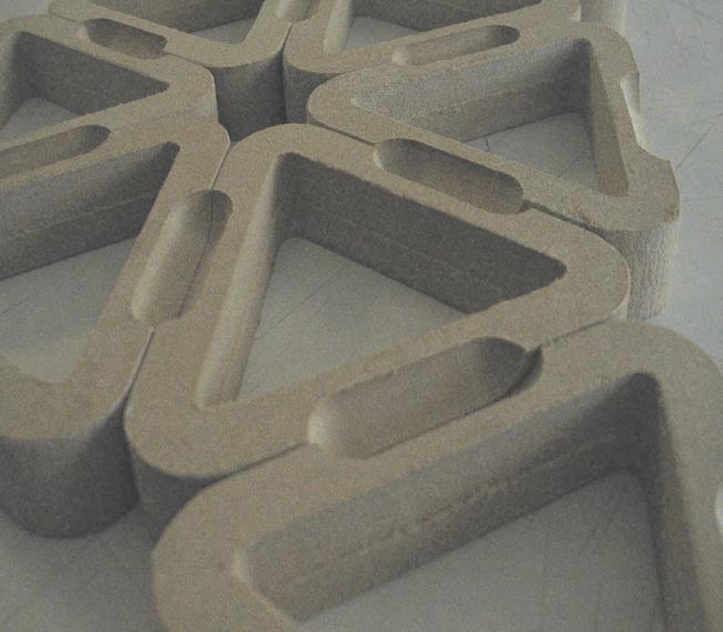
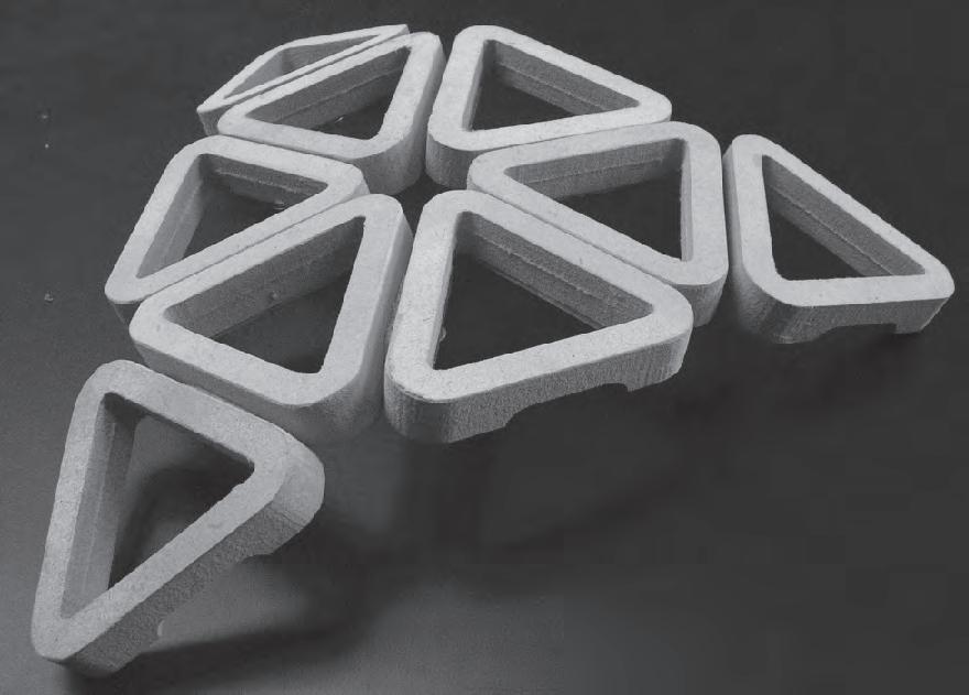
Analog Experiments Mechanics set 1a
Uniform triangular tessella with intercellular captive gel and collective performance
Locked articulations
Articulated edges
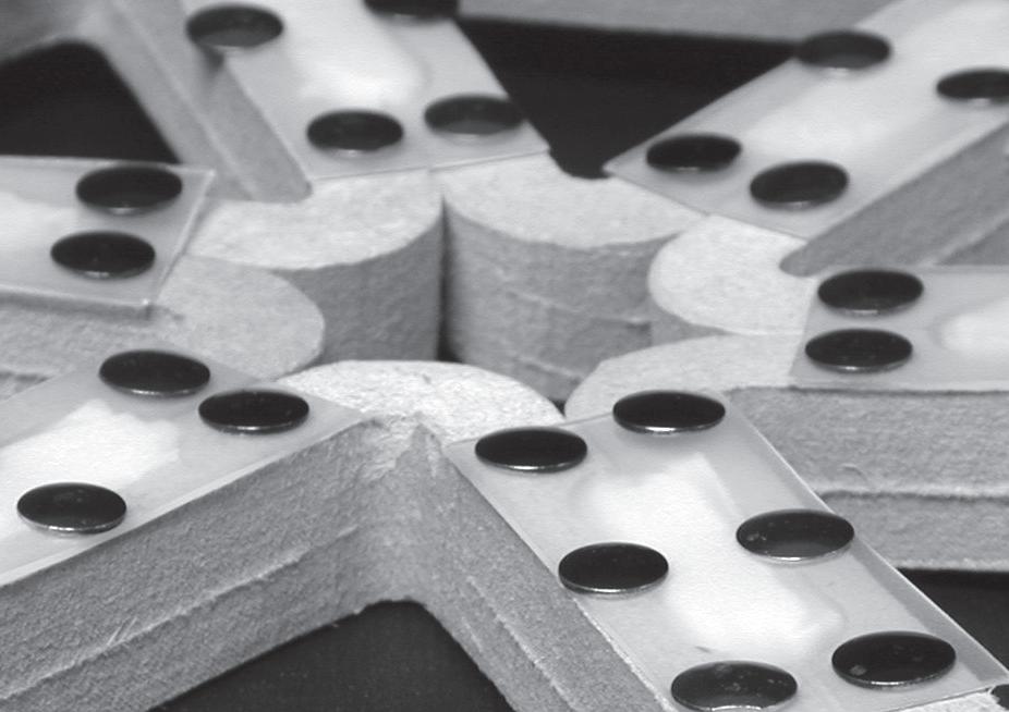
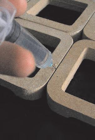
After the familiarization with pneumatic properties of the swellgel introduced during the Biomimetic seminar course a new generation of experiments where developed using the same material but with a different approach. This set of experiments is aimed to investigate the expandable forces transmitted by the Gel. With the muscles, the expansion of the material is converted into a tension force thanks to the pipes where the gel is placed. In this case the investigation is focused in the direct transmission of the forces from the gel to the neighbours cells.
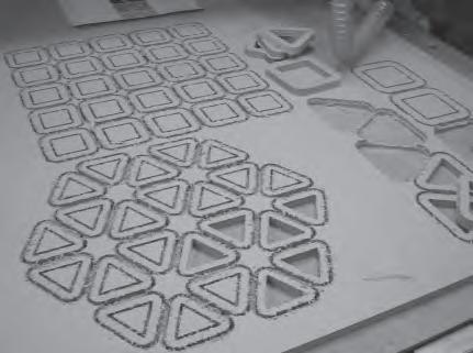
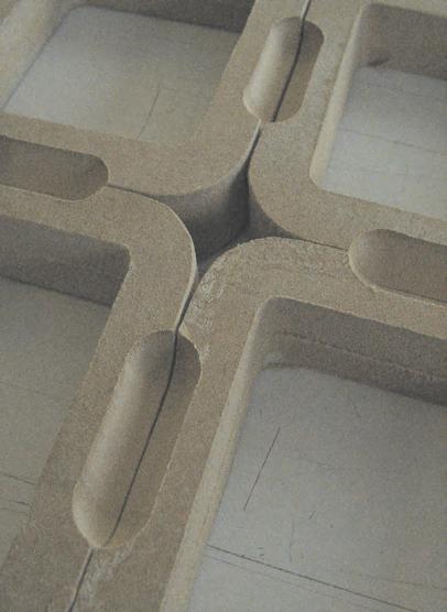
So this is actually the first attempt to combine the dynamic devices with the fixed parts of the system as it was previously explained in the conceptual chapter of the material system. On the other hand this experiment only focuses on the mechanical properties, so all the cells are equal in size. Nevertheless the same experiment was made with triangular and square cells. Due to the number of cells involved in the models, they where cut with CAD/CAM technologies. In the edges of the cells a quarter of a pipe was removed from the material (MDF). Then, as the cells where arranged together this sections will form a pocket that will describe a half pipe. This pocket is the receptacle where the swellgel will be placed, after it has been contained in a pillow of elastic mesh. This pillow is placed in the pocket, then the space is closed by a thin plastic membrane that has two purposes: one, to delimit the space of expansion and two, to perform as a hinge between the cells.
From the mechanical point of view the experiment was successful. The pneumatic forces of the expandable swellgel are transmitted to the neighbouring cells and the system re-configures itself switching from flat to convex configuration. At the same time the new shape can support two times its own weight (500grms). On the other hand it is very difficult to predict the amount of curvature that the system will achieve. Also some of the articulations get locked due to geometrical characteristics of the triangular organizations.
Overall reconfiguration
“The pneumatic forces of the expandable swellgel are transmitted to the neighbouring cells and the system re-configures itself switching from flat to convex configuration”
CAD/CAM cutting process
Pillow with gel into pocket closed by hinge.
Pre arrangement of tessellas.
018
Activated system
Analog Experiments
Mechanics set 1b
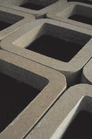
Uniform square tessella with intercellular captive gel and collective performance
Locked articulations
Articulated edges
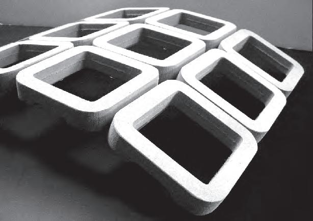
The experiment described previously was carried out again, but this time using square cells instead of triangular ones. What was observed in this case, was that the amount of curvature collectively achieved was bigger than the one achieved with the triangular configuration. This resulted from the parallel arrangement of the articulations, therefore the degree of the angles between cells was directly translated in the more pronounced curvature. On the other hand 8 out 17 edges were locked which makes the percentage higher than in the triangular configuration where 4 out 9 edges are locked. In relation to the lock/unlock edges it is interesting to quote that the direction of the curvature can change according to the activated edges (U or V direction throughout the surface).
Like in the previous one, this experiment proves that it is difficult to control the amount of curvature, since there is no mechanical or geometrical device to set or lock the overall system. This fact will be an issue that will determine the later development of the material system investigation.
Overall reconfiguration
“this experiment proves that it is difficult to control the amount of curvature, since there is no mechanical or geometrical device to set or lock the overall system”
019
Activated system
Analog Experiments Mechanics
Set 2
Reversible porosity in membrane placed in individual tessella
Variables:
_3 sided cells
_4 sided cells
_Porosities activation in the system
_Local scale
_Forces transmitted directly by the expansion of gel
4 sided 3 sided articulated locked porous local regional global press on tension Exp. 1 Exp. 2 Exp. 3 Exp. 4 Exp. 5 Exp. 6 Exp. 7
020
Analog Experiments Mechanics Set
2
Reversible porosity in membrane placed in individual tessella.
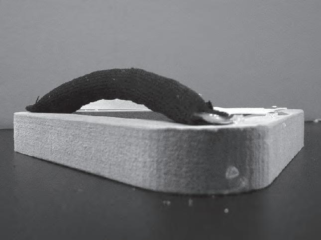
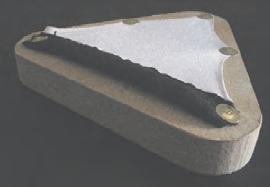
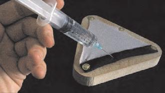
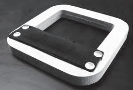
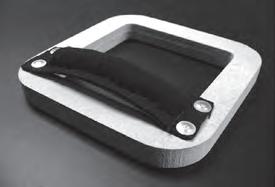
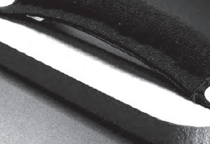
This set was made using the same materials like in the previous experiments. But in this case the research is focused on a local scale. Like in the previous one, in this test the gain in volume of the swellgel was transmitted directly as an expansion force. The gel was contained into a tube made out of elastic tissue. The tissue, as the non-elastic pipes, can only deform in one direction, in this case in a longitudinal one. Since the edges of the tube were fixed to the frame of the cell, as the tube grew in length it also curved. Since it could not move towards the frame, it grew upwards, creating an opening at the edge. This operation can be performed either in three, or four sided cells. Also the openings can be placed in one or more sides of the cells.
As it was concluded earlier elastic membranes in combination with pneumatic devices were not a very successful combination in order to construct stable structures. And since in order to perform, the configuration above needs elastic membranes between the tubes an extra caution has to be taken.
“The tissue, can only deform in one direction, in this case in a longitudinal one. Since the edges of the tube were fixed to the frame of the cell, as the tube grew in length it also curved. Since it could not move towards the frame, it grew upwards, creating an opening at the edge”
Re-configuration Activated system 021
Triangular
cell relaxed
and under stimulation Square cell relaxed and stimulated

Analog Experiments
Mechanics set 3
muscles re-design and mechanics observations
Variables:
_Regional scale
_Forces converted from expansion into tension
4 sided 3 sided articulated locked porous local regional global press on tension Exp. 1 Exp. 2 Exp. 3 Exp. 4 Exp. 5 Exp. 6 Exp. 7
022
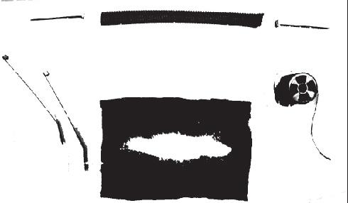
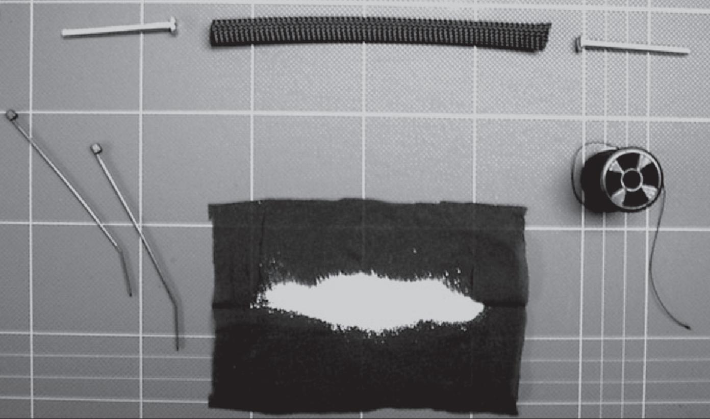
1_50x3mm bolts, ends and attaching devices
2_bi-directional elastic pipe (TECHFLEX)
3_100mm. plastic ties
4_multidirectional elastic fabric
5_0.2grms. watering gel
6_thread
Above are specified the materials used for the construction of the updated muscles. Their design was approached by taking in consideration the scale of the models intended to build and also the production techniques, making them cheaper and quicker to build. Firstly, the swellgel is wrapped into semi-permeable elastic mesh, where the ends are knotted. This component was driven inside of the TechFlex pipe, that was then closed with the heads of the bolts. Finally, using plastic ties the bolts and the ends of the pipe are attached together. The part of the bolt going to the outside of the muscle could be screwed into an external nut. Some later muscles where constructed using a cord with a knot on the inside instead of the bolts, this was made with the purpose of achieving more flexibility an also because the component worked only under tension.
This experiment was consider successful since the muscles served the purposes of the dynamic devices in the later models where they were introduced. If the design needs to be scaled up to 1:1 size, the concept will work but some aspects of the design may need a reconsideration, for instance the material used to wrap the swellgel.
Mechanics set 3 muscles re-design and mechanics observations 1 2 3 4 5 6
Analog Experiments
023


1_6x150mm. relaxed


2_6x150mm. contracted Contraction=85%
3_6x100mm. relaxed
4_6x100mm. contracted Contraction=90%
5_4x150mm. relaxed
6_4x150mm. contracted Contraction=80%
7_4x100mm. relaxed
8_4x100mm. contracted Contraction=85%
9_watering process
water exposure_1 minute reaction_15 minutes
relaxation thin muscles
2 hours at room temperature
relaxation thick muscles
2 1/2 hours at room temperature
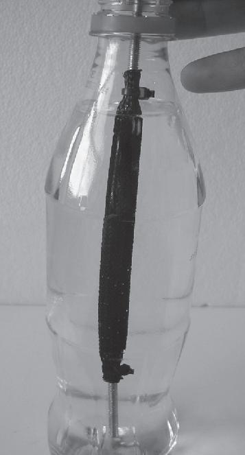
Before the implementation of the muscles in the rest of the models (fixed parts), some series were constructed using different diameters and lengths of the pipes. The output of the observation proved that if the pipe is thinner, the percentage of contraction (in length) is higher. This means that using thinner pipes will allow more pronounced articulations or changes in later models. On the other hand during the watering of the muscles, there were not observable differences in the stimulation process, so the maximum level of contraction was achieved in 15 minutes by all the muscles. Nevertheless during the relaxation process, it is interesting to note that when the thinner muscles have less material inside them, the process is quicker, due to the less amount of water to be released.
During the observations, one important fact to realize is that with the muscles it is possible to predict exactly how much contraction will be achieved in terms of length and forces. This is a very important step forward in relation with the previous mechanical experiments, where it was very difficult to control or predict the variations of the system behaviour after the stimulation process.
1 2 3 4 5 6 7 8 9
Analog Experiments Mechanics set 3 muscles re-design and mechanics observations
024
Muscles configuration in early model. Is interesting to note that angle of the fold in the pictures sequence is much pronounced in the middle articulation. This is due to the overlay of muscles at that articulation.
Stimulation and reaction sequence in a lapsus of 20 minutes.


With the aim of making a relation between the technique of ”captive swellgel between cells” and external muscles, one previous model was equipped with “external to the cells” dynamic devices. The first observation was that the amount of articulation was successfully predicted, on the other hand it is important that this was achieved using only 50% percent of the pneumatic material (swellgel) used by the same configuration without the external muscles. This realization is very valuable since at the end it means that the system needs less water to react and requires less time to come to the relaxed configuration (due to the quicker evaporation process). This added to the fact that the geometrical output of the experiments is more controllable makes the decision for the use of external muscles as the pneumatic devices easier.
Finally the system needs 25% more time to re-configure after the stimulation than the time taken by the muscles alone. This is due to the loads added to them.
“this was achieved using only 50% percent of the pneumatic material (swellgel) used by the same configuration without the external muscles”
1 2 3 4 5 6
Analog Experiments Mechanics set 3 muscles re-design and mechanics observations
025
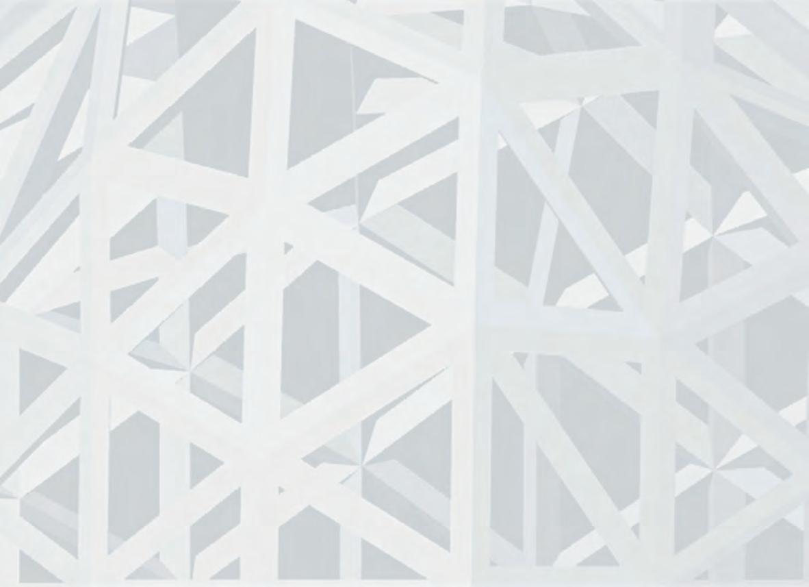
Introduction to the concepts of parametric design.
Despite the fact that in the background chapter some parametric experiments where exposed. At this point of the research this powerful tool is incorporated in the development of the material system.
To understand the essential difference between an explicit geometric model and a parametric model, imagine a digital drawing of two circles with a line connecting their centre points. In an explicit geometric model, any change in the position of either of the circle will require the redrawing of the connective line. In a parametric model, a relentionship between the centres and the line can be established so that the line will follow any translation of either circle. Other relationships can also be prescribed, for example between the length of the line and the radius of one of the circles. This association can then be given a conditional statement, such as one preventing the two circles from intersecting. And so on. All predefined geometric relationships applied through parametric expressions and constrains remain consistent as the model is manipulated.
Extract from “Pluripotent Components and Polymorphous Systems”, AA Files 52 by Achim Menges
Analog Experiments
Geometry set 4
Parametric tessellas for three and four sided cell configurations
Variables:
_3 sided cells
_4 sided cells
_Articulated organizations
_Locked organizations
Regional scale
4 sided 3 sided articulated locked porous local regional global press on tension Exp. 1 Exp. 2 Exp. 3 Exp. 4 Exp. 5 Exp. 6 Exp. 7
C_1.3.2 026


Parametric tessellas for three sided cell configurations.
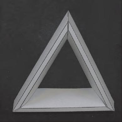
At this point of the research where the mechanical properties of the articulations between cells and the pneumatic actuators have already been investigated and incorporated as components of the material system, the focus of the experiments switches towards the parametric definition of the geometries already investigated. Therefore parametric models of triangular and four sided cells are modelled within Generatives Components. The aim so far is only focused on the geometrical logics of proliferation and production techniques. Thus, there are not pneumatic or any other kind of dynamic devices incorporated in the experiments.
In the case of the triangular tessella, four points are defined as control points for each component, one for each vertex and another external point that defines the orientation of the external faces and therefore where the edges will meet. The distance of the external point will also define the thickness of the frame in relation of 1/10 of the distance.


Analog Experiments Geometry set 4a
P_3 P _4 P_1 P_2 P_P_ 3 P_P_ 4 P_1 P_2 P_4 Plan View Side View X/10 X
Diagram of geometry principles in triangular component.
027
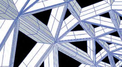
Sequence of parametric activation of a component by the manipulation of the external to the frame point.
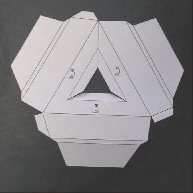
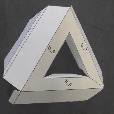
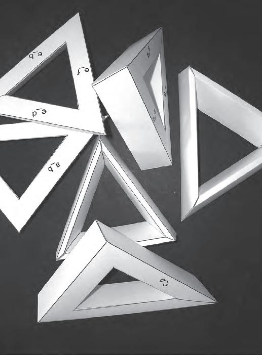
1_shell with nested components (digital)
2_component unfolded
3_component semi-folded
4_component ready
5_components pre assembly
6_ assembled components
Analog Experiments
Geometry set 4a
Parametric tessellas for three sided cell configurations.
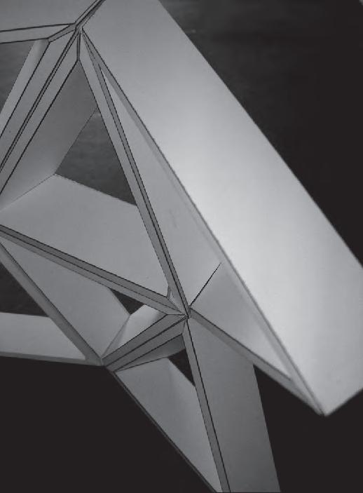
In relation with the construction concept of the model, the technique used is: unfolding the digitally modelled component, cutting the shape and later folding back the material to conform the analog shape. This process is widely used in various industries including architecture. Also it allows an easy transition from the modeling with cardboard or paper to the bigger scale of any sheet material such as steel or aluminium. The geometry is modeled in GC, unfolded in Rhino and then cut and folded by hand.
Therefore these first models aim to corroborate the construction process defined and also investigate the interrelation between a larger number of neighbouring cells. In relation to this, the perfect match between neighbouring cells is secured by the sharing of control/input points of adjacent tessellas, while the fourth external point defines the equal thickness of the frames. This configuration can be achieved either by placing isolated points in the space or by the population of a surface described by points.
After the mechanical experiments described previously (set 1) the strategy defined from now on, moves towards the use of triangular cells as the lock part of the system. Later on the pneumatic devices will be incorporated, but acting within the frame of each individual cell. At this point of the process the design is moving towards the definition of a gridshell type structure.
“This process is widely used in various industries including architecture. Also it allows an easy transition from the modeling with cardboard or paper to the bigger scale of any sheet material such as steel or aluminium”
1 2 3 4 5 6 028
Diagram of geometry principles in triangular component.
Side View of array of articulated components under tension.



Sequence of parametric activation of a component by the manipulation of the the frame and the external to the frame point.
Analog Experiments
Geometry set 4b
Parametric tessellas for four sided cell configurations.
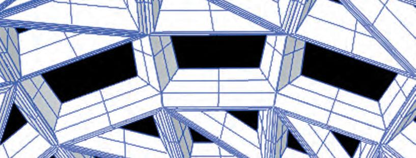
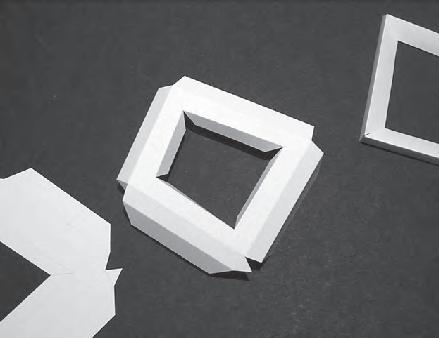
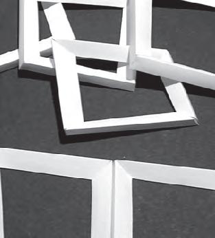
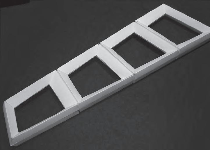
This four sided component shares the geometrical principles described in the three sided component. In this case five points are defined as control points for each component, one for each vertex and another external point that defines the orientation of the external faces and therefore the edges where these faces met. The distance of the external point will also define the thickness of the frame in a relation of 1/10 of the distance.
Despite the similarities between the logics of triangular and four sided cells, in this case the experiment investigates the possibility of a collective articulation. The option of doing this with four sided tessellas is due to the analysis of the previous experiments (set 1) where the “collective articulations behaviour” observed where more successful with this configuration.


Plan View Single Component Side View Single Component
P_1 P_2 P_3 P_4 P_5 P_1 P_2 P_5
Side View of array of articulated components relaxed.
029
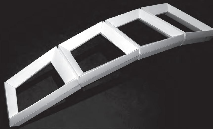
external angles of the components defines the degree of collective curvature
Analog Experiments
Geometry set 4b
Parametric tessellas for four sided cell configurations.
1_shell with nested components
2_folding sequence
3_components assembly
4_articulated tile relaxed
5_articulated tile under traction forces
The construction process explained in experiment 4a is repeated here, the only difference is that in this case the different cells instead of being attached together by the external faces, are connected by a hinge. Thus the array of cells is one articulated body. So the specific angles of the external faces of the cellular frames are defining two different settings for the patch. One in a relaxed state and the other in a state of curvature (supplied potentially by the muscles).
This set of parametric experiments (set 4), proves to be a very important new input for the development of the material system. Nonetheless the geometrical relation of the experiments does not have a particular purpose further than the investigation of the construction processes and the quality of the structural and mechanical properties of the models.
1 2 5 4 3 030
Analog Experiments
Geometry + Mechanics
set 5
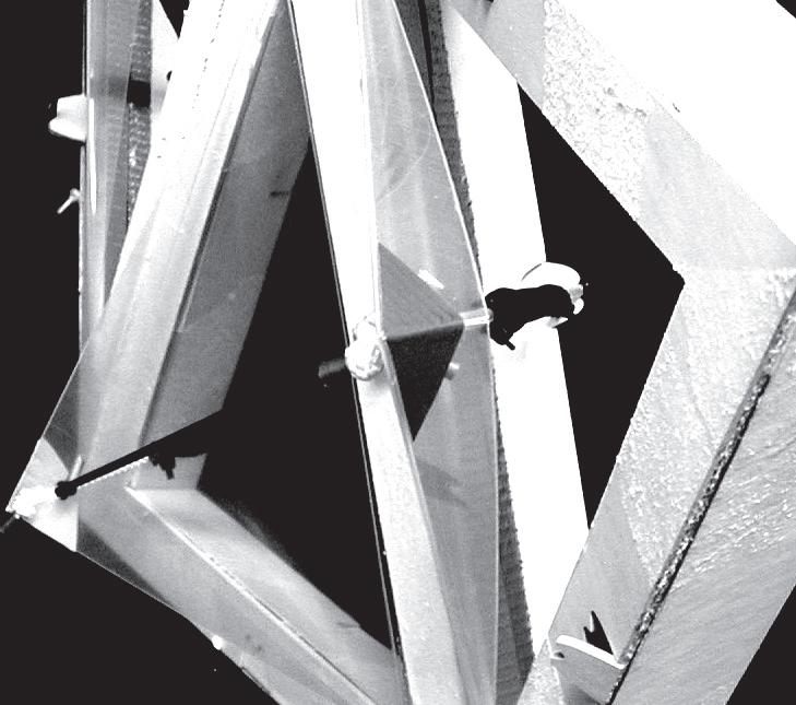
Parametric triangular porous tessellas, activated by pneumatic muscles.
Variables:
_3 sided cells
_Locked organizations
_Porosities activation in the system
Local scale
_Forces converted from expansion into tension
Contains experiments set 3 and set 4.
4 sided 3 sided articulated locked porous local regional global press on tension Exp. 1 Exp. 2 Exp. 3 Exp. 4 Exp. 5 Exp. 6 Exp. 7
C_1.3.3 031
Analog Experiments
Geometric diagram of model, inputs points and unfolded pieces (not in the same scale)


Sequence of parametric manipulation of model


Parametric triangular porous tessellas, activated by pneumatic muscles.
In this set of experiments, CAD/CAM technologies were introduced in the production techniques, using the procedure of unfolding, laser cutting and assembly. From the geometrical point of view, the model is constructed with the paremetric logics developed before. The inputs needed for the nesting procedure of the cells are seven points. Two of them are shared by three cells, another two are shared by two cells and two more are used only by one cell, finally the external point is shared by all the four cells. This secures the perfect match between components and the geometrical logics shared by them. As in shown in the sequence of images below the system can be reorganized in different configurations but relations establish in the parametric model remain consistent. The approximated scale for this model is 1:10.


Geometry + Mechanics set 5
P_1 1 cell P_2 2 cells P_3 3 cells P_4 1 cell
2
3 cells P_7 All cells
P_5
cells P_6
032

Parametric triangular porous tessellas, activated by pneumatic muscles.
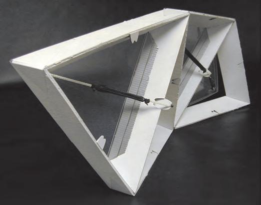
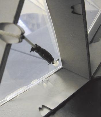
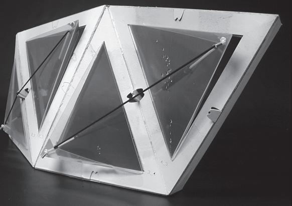
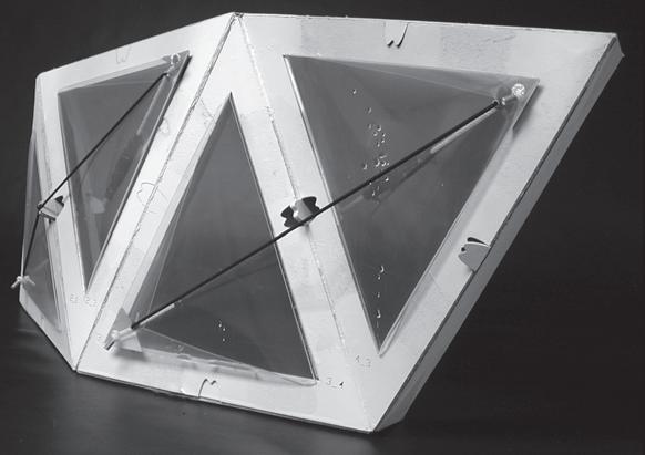
In this experiment the triangular cells are equipped with “flaps like” openings, the openings are three sided aswell and in one of the sides there is a hinge that is attached to the frame. The openings are organized in two pairs; each pair shares the section of the structure where the hinges are attached. They also share one set of muscles, the muscles are organized in pairs ant they use a common elastic thread as a reversible device.
The aim for this experiment is to test in a local scale the influence of water in the system. The input of water in the muscles will make it switch from an open configuration to a close one. The openings are consider as porosities, so if the components are proliferated into a larger structure, the collective reaction to the external input of water will make the system reacts together to the environment, switching from permeable to a sealed shell.
On the other hand, this experiment is the first one to combine the geometric logics developed for parametric cells, together with dynamic devices. Also at this point of the research there are some very important facts arising. A is the relation between an external environmental input (water) and the potentials of the material system as a passive reversible organization that control its permeability.
“The openings are consider as porosities, so if the components are proliferated into a larger structure, the collective reaction to the external input of water will make the system reacts together to the environment”
Analog Experiments Geometry + Mechanics set 5
Front View Right View Top View
Left View
Openings relaxed, under stimulation, and detail of porosity closed.
Esquematic section drawing of two cells and a pneumatic devices set.
033
muscles reversible device flap frame Action Reaction


4x150mm. Relaxed and contracted muscles
Contraction percentage=80%
Parametric triangular porous tessellas, activated by pneumatic muscles.
10 min.
Reaction to injected input
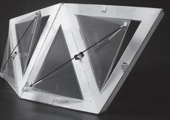
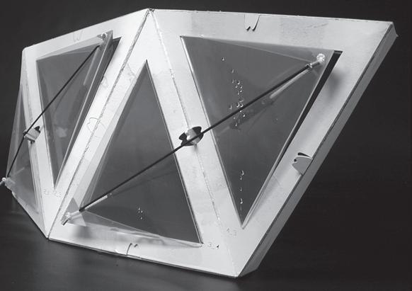
As is shown in the sequence of images, after the stimulation of the muscles, the closing process of the porosities happens in a coordinate manner. Therefore the system permeability changes all together at one time. In this experiment the cells were stimulated injecting the water into the muscles. The aim for the system in real scale is to define a way to introduce the water collected from rain fall into the muscles. As is been say before, the system should be passive, without external devices such as engines, bombs or controllers. Nevertheless at this point is important to concentrate on that the muscles are stimulated individually by the environment, thus they react as isolated entities. But, due to the multiplication of isolated actions, the whole system achieves a complex behaviour, changing its overall permeability to the environmental influence of water.
In relation with the size of the openings, they are negotiated between the degree of permeability and the amount of traction that a muscle can perform. In this experiment the muscles contracted down to the 80% of their initial lengths. On the other hand, the size of the opening when the muscles are fully relaxed, reaches the 40% of the open area within the cell frame.
In relation with the stimulation process, when the water is injected directly into the muscles, the reaction time is 5min. faster than when the muscles are soaked.
“after the stimulation of the muscles, the closing process of the porosities happens in a coordinate manner. Therefore the system permeability changes all together at one time”
Analog Experiments Geometry + Mechanics set 5
1 3 2 4
Sequence of coordinated porosities closure procedure.
034
Analog Experiments
Geometry + Mechanics set 6
Articulated collection of “parametric four sided porous tessellas” activated by pneumatic muscles.
Variables:
_4 sided cells
_Articulations between cells
_Porosities activation in the system
Local scale
_Forces converted from expansion into tension
_Contains experiments set 3 and set 4.
4 sided 3 sided articulated locked porous local regional global press on tension Exp. 1 Exp. 2 Exp. 3 Exp. 4 Exp. 5 Exp. 6 Exp. 7
035
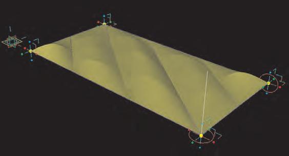
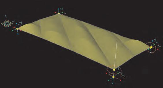
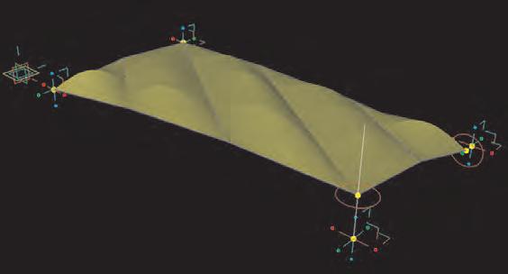
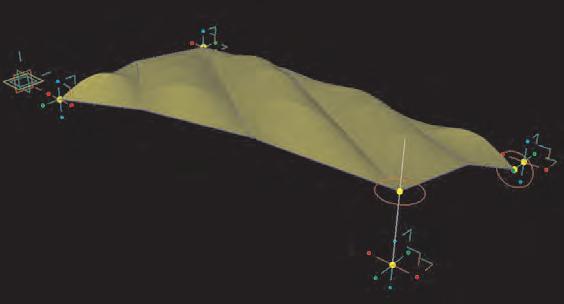
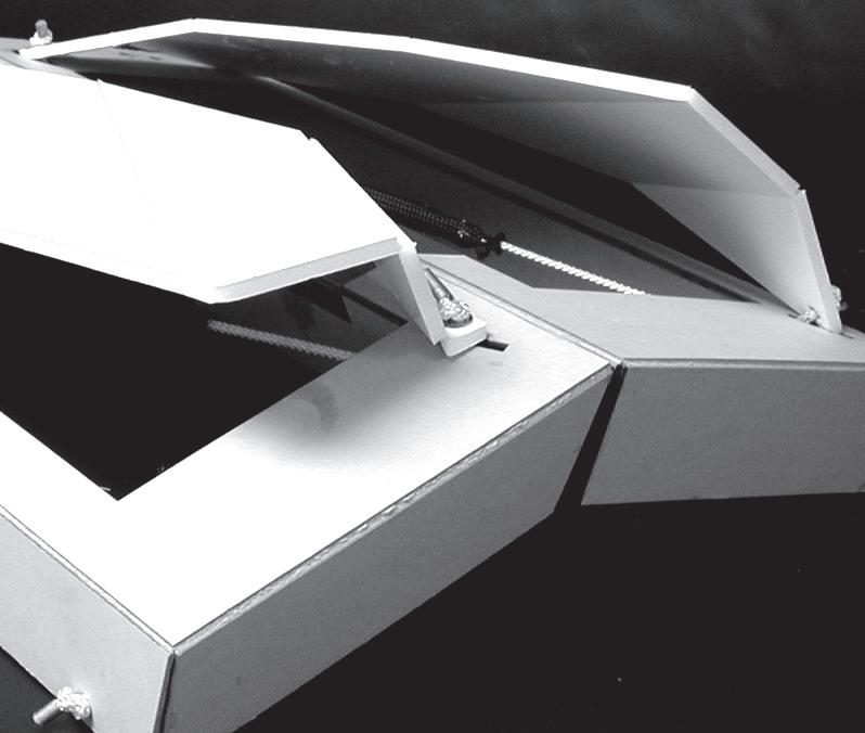
The aim for these experiments is to combine articulations between cells together with porosities in the cells. Also due to the geometric setup of the porosities, they are opening instead of closing under the stimulation process. The construction technique is the same one described in the previous experiment (CAD/CAM).
Performance diagram Action Reaction
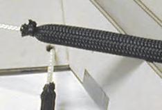
The geometric logics involved in the articulations between cells in this experiment are the same ones described in set 4b, thus the angles predefined in the cell frames will control the degree of articulation driven by the tension of the muscles, therefore the overall curvature. On the other hand these porosities react in a different manner to the ones revised before. In this case the porosity is an articulated rigid membrane with diagonal lines, the tension is performed between to opposite angles of the membrane and the direction of the muscles is inverted to the direction of the lines, allowing the articulation. The four angles of the porosity are fixed to the frame in a specific manner in order to allow the proper mechanic reaction: Number 1 and 3 are semi loose, having a line of displacement. Number 2 is the only one fixed to the frame while 4 is free. As the tension force is performed by the muscle, points 1 and 3 displace getting closer one with another. As this generates the articulation of the membrane, point 4 moves upwards generating the opening. The percentage of opening in the relation with the size of the interior space of the frame is up to 70%. The scale of this experiment is approximately 1:10. P_1 P_2 P_4 P_3


b 6 b 6 b 5 b 4 b 4 b 5 Analog Experiments Geometry + Mechanics set 6
1 2 3 4 5
Articulated collection of “parametric four sided porous tessellas” activated by pneumatic muscles.
Model 3d View and unfolded pieces.
036
Parametric model of the articulated membrane reacting to traction forces..
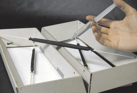
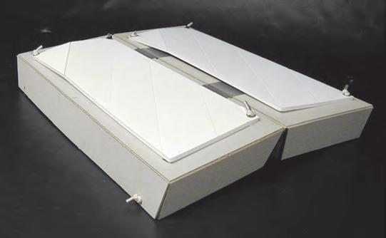
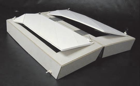
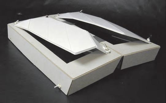
Articulated collection of “parametric four sided porous tessellas” activated by pneumatic muscles.
The analog model constructed for this experiment was conformed by two cells and their porosities. The articulation between the cells is controlled by one muscle of 150x8mm. On the other hand the porosities are activated by muscles of 120x4mm.
The experiment combined successfully different isolated experiments undertaken before. It also proved that the technique developed with the material system can be used in different kinds of geometries and with different purposes. The results observed in this particular model, suggested the use of the resulting openings as a source of light, rather than as a ventilation device. In relation to this, the problem is the correct association between more light and at the same time more ventilation, because in general darkness is associated with bad weather and brightness with good weather, so there is a mismatch. Theoretically a flexible transparent membrane can be placed between the opaque articulated opening and the cell frame. Thus when the system reacts to water the cells open, then due to the size of the opening this system can potentially achieve a high degree of light permeability.
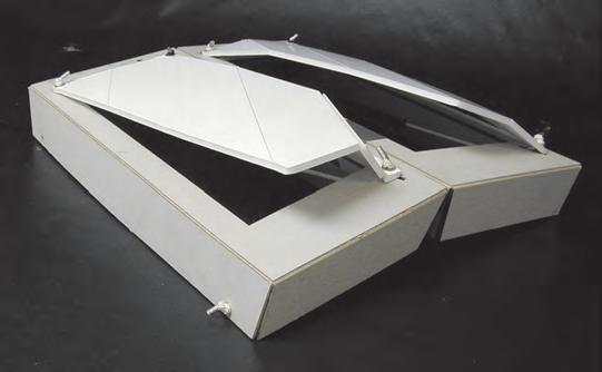
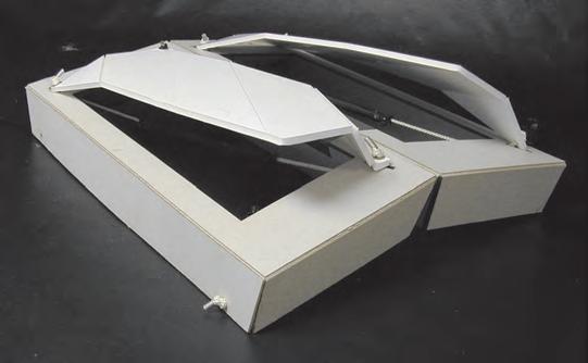
“It also proved that the technique developed with the material system can be used in different kinds of geometries and with different purposes. The results observed in this particular model, suggested the use of the resulting openings as a source of light, rather than as a ventilation device”
10 min.
Reaction to injected input

Analog Experiments Geometry + Mechanics set 6
1 2 3 4 5 Stimulation process
Sequence of simultaneous change in permeability and angle between cells.
Detail of semi loose point and line of displacement
Detail of inverted muscles and their relation with the rest of the system, in the case of the lower one, it goes trough the frame and is fixed to the “semi loose” angle of the membrane, so the cord attached to the muscles displaces trough the frame.
037
Analog Experiments
Geometry + Mechanics
Set 7
Parametric patch with lock and articulated sections, collective geometrical re-configuration.
Variables:
_3 sided cells
_4 sided cells
_Articulations between cells
_Locked cells
Local scale
_Regional scale
_Forces converted from expansion into tension
_Contains experiments set 3, set 4 and set 6.
Exp. 1 Exp. 2 Exp. 3 Exp. 4 Exp. 5 Exp. 6 Exp. 7
4 sided 3 sided articulated locked porous local regional global press on tension
038
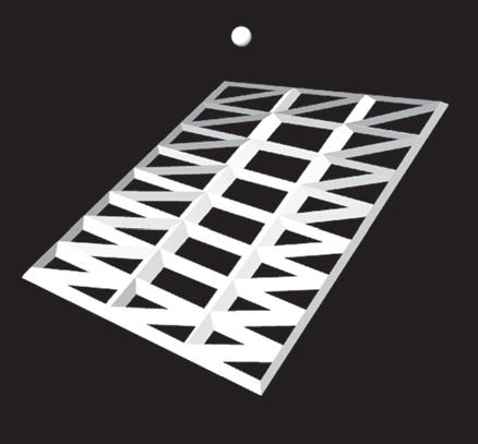
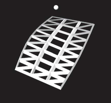
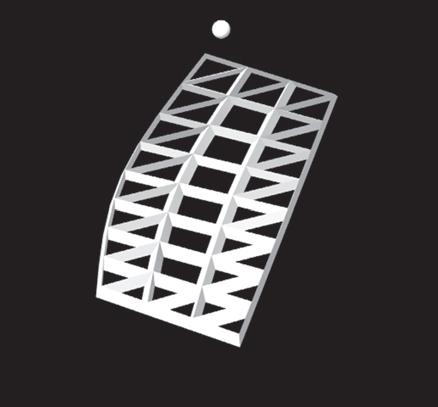
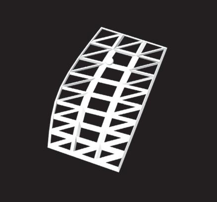
Concave and anticlastic geometrical configurations, extracted from the same parametric model.
Parametric patch with lock and articulated sections, collective geometrical re-configuration.
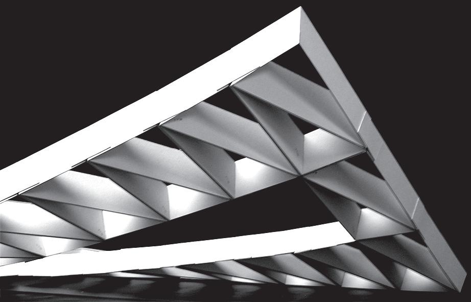
The aim for this model is focused on the relation between the lock parts of the system (conformed by triangular cells) and the articulated ones (conformed by four sided cells). This is due to observations which make evident the dependency of articulated sections to fixed elements in order to have a structurally stable system. With this purpose a parametric patch is designed where 6 “four sided tessellas” where located into a frame constructed with 36 triangular components.
The geometric relations of the model are defined by the population of a parametric surface controlled by six points. At the same time the surface is subdivided by a collection of points, finally another point is located outside of the surface. The components are placed using the points on the surface and the external one, according to the logics of the three and four sided components explained in experiment set 4, where the external points defines directionality and thickness of the components. This model allows the manipulation of its shape, therefore can be related to patches of a larger system where isolated geometrical sections can be investigated. From this parametric organization, two analog models were constructed, a convex one and another with anticlastic curvature. Here the observations are focused in the first one.
“due to observations which make evident the dependency of articulated sections to fixed elements in order to have a structurally stable system”
Analog Experiments Geometry + Mechanics Set 7
039
Series of parametric variation by manipulation of the surface and the external to the surface point.

Analog Experiments
Geometry + Mechanics Set 7
Parametric patch with lock and articulated sections, collective geometrical re-configuration.
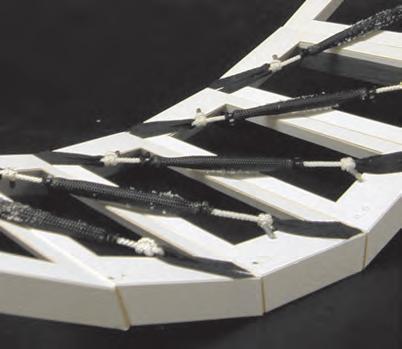
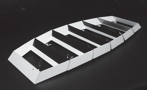
The convex output of the parametric model is constructed using the (CAD/ CAM) unfold technologies described before. This particular model aims to be a study model, where geometric and mechanical behaviours are investigated. Nevertheless the shape of the model can be related with a roof, in deed with out been very specific, the changes operated on the model are until some extend referred to practical applications in a structure with covering purposes. In this case the changes on the permeability are not thanks to the collective opening of porosities, instead is due to the operation of several articulated cells that will inform a larger part of the system changing its overall shape. This action is translated into major geometrical and topological variations on the roof surface, where big gaps are described between the lock and the un-lock parts of the system. This gaps are switching from open (when is relaxed) to close (when is stimulated). In the model the cells where left empty, therefore to understand the changes of permeability we have to assume that they are closed by some kind of membrane.
“In this case the changes on the permeability are not thanks to the collective opening of porosities, instead is due to the operation of several articulated cells that will inform a larger part of the system changing its overall shape”
7 b_ c_6 8 8 c c_10 b_ c_12 c_14 c_15 b_ c_16 b10 a5 4 a b_ b_ b_ 9 a_10 a_1 a_2 b_ 2 1 5 1 b_ a_3 b_ 31 a a_16 a_14 a_12 4 c 5 c_1 c_
Front View
Top View
Side View
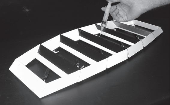
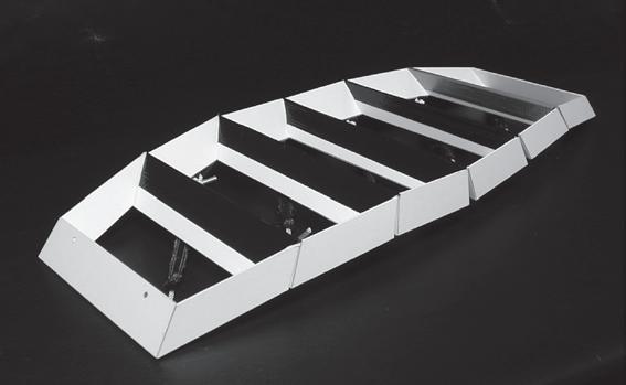
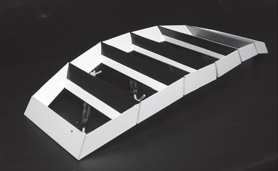
Un-assambled components, articulated section of the system under traction, detail of muscles attached to cell frames.
040
Assembled models and un-fold pieces

Set 7
Parametric patch with lock and articulated sections, collective geometrical re-configuration.
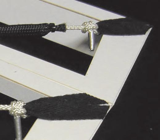
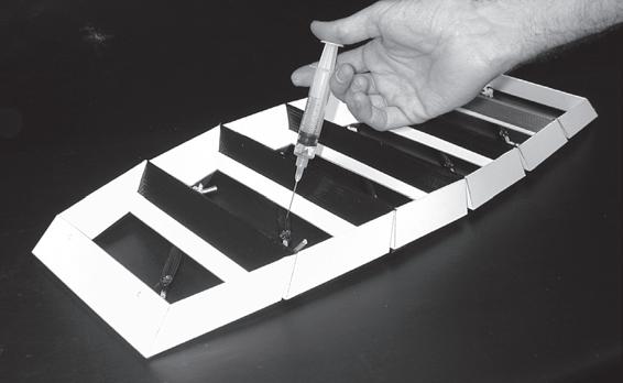
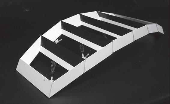
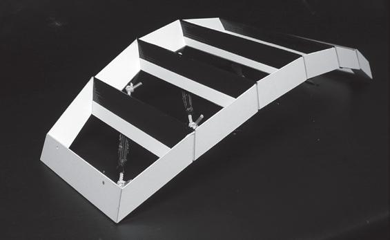
Before organizing the lock and un-lock parts of system together, the articulated patch was taken under the stimulation process on its own. This allows a better understanding of the physic principles that occurs during the articulation process. In the model, between any two neighbour cells there is a muscle placed in diagonal between them, therefore there are in total five overlaid pneumatic devices. After the stimulation process each of them attracts two of the cells together until the external faces of the frames match in a predefined angle. When all the muscles are fully contracted the output is a continue arch with the structural capacities to carry five times its own weight.
It is important to note that despite the fact that the overall articulated organization can be seen as one, the global performance is achieved by the actions of local actuators.
“After the stimulation process each of them attracts two of the cells together until the external faces of the frames match in a predefined angle”
10 min.
Reaction to injected input
1 2 3 4 5 6 7 8
Analog Experiments Geometry + Mechanics
041
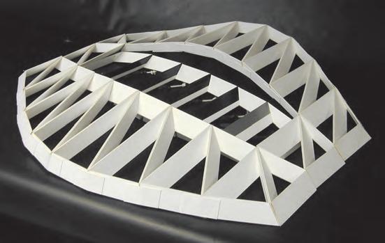
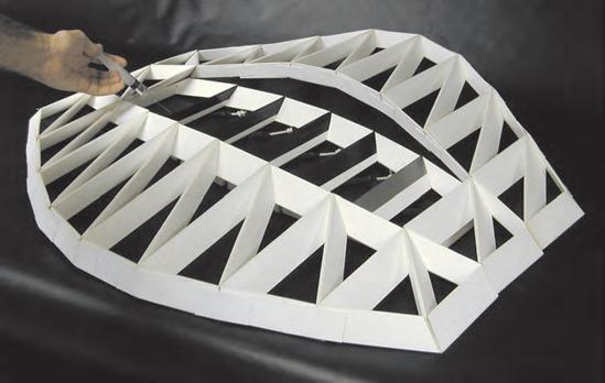
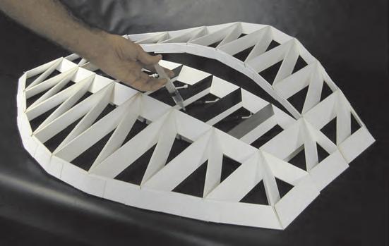

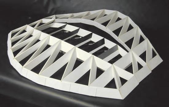
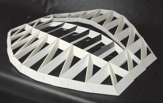
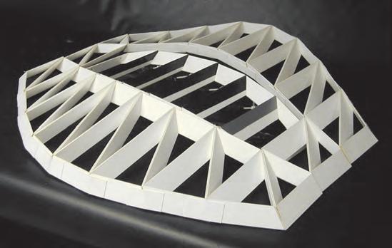
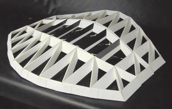
Taking the case of a roof configuration, and assuming that the locked frame of the model can be supported by pillars or placed in a hypothetical peripheral wall, the articulated part of the middle hangs in a relaxed manner leaving gaps between its sides and the locked frame. As the pneumatic devices are stimulated, the articulated patch achieves curvature thus the gaps get closed. Thus the structure switches from a permeable to a sealed one.
This collective reaction can be repeated many times in a larger system. Again the material system suggests that the combinations between dynamic devices and cells (and the changes operated by them together) are endless.
At this point the chapter of analog experiments is temporarily closed. The experiments had informed the forthcoming path of the investigation, where different types of programmatic implementations for the material system are studied. On the other hand analysis of environmental issues are addressed aiming to tune the material system with potential locations , and also to relate it with environmental factors such light, wind and water.
“As the pneumatic devices are stimulated, the articulated patch achieves curvature thus the gaps get closed”
10 min.
Reaction to injected input
1 2 3 4 5 6 7 8
Geometry + Mechanics
Analog Experiments
set 7 combined cells in parametric patch_ logic
042
The partial conclusions taken from the project relate to the parts of the system and the relations between them.
Firstly, the mechanical system investigated has successfully proved that using two main components for the structure (cells and muscles) it is possible to achieve a huge range of different and specific dynamic behaviours. The set of tests performed has identified two main categories of interactions, which will be the focus of our conclusions: single and multiple.
The action of single cells naturally produces local changes to the pattern, resulting in a switch, which is reversible, from open to close. Nevertheless, if this behaviour is multiplied by use of several components embedded in the system, the result is in a complete topological change in the pattern hence a change to the permeability and ventilation of the system.
A multiple effect results from the collective interaction of neighbouring cells. The outcome of this is a substantial alteration to the shape and topology of the pattern in a regional scale.
In relation to the “passive _ reversible _ dynamic” interactions of the structure, all the sets of experiments have evidenced the dependency of the structure on its static or locked points. Thus the dynamic parts of the pattern are always a function of the secure parts.
The input for both results is the same: water extracted from the environment where the structure is placed. In relation to this, the key to this investigation is how to use, in an instrumental way, the one single physical interaction of the pneumatic devices developed. Therefore the proper combination of geometry, dynamic devices and environment will produce an efficient climatic envelope.
In the next chapter of the dissertation, the work is conduced towards the empirical corroboration of theories formulated during the previous research. In order to achieve this, contemporary buildings and previous experiences in the context of the Emergent Technologies program are addressed. On the other hand environmental issues are suggested as an informing body of parameters for the material system.
Partial conclusion C_1.4 043
Chapter two
Material system contextualization with design strategies
044
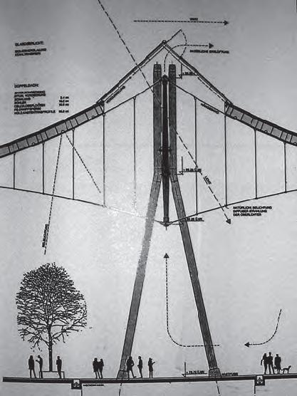
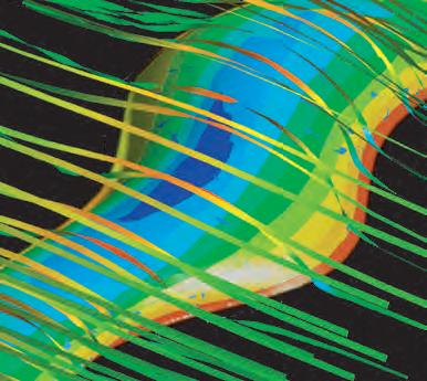
Climatic control +program + dimensions
Architects von Gerkan, Marg and Partner, Hamburg
Structural engineers: Schalaich, Berger-mann+Partner, Stuttgart.
The structure developed so far, suggested applications for large open spaces, therefore exhibition pavilions are an interesting case to look at. In the case of this specific building what is more interesting are the concepts of passive ventilations and climatic control systems. This is observed in the double glazing of the facade and in the mechanism at the top of the roof where openings are located. In these areas, low pressure is generated due to the shape of the roof and the direction of predominant winds. The design also considers sun light exposure and its effects on the movement of air volumes inside the building due to different temperatures in the space.
This building fulfills successfully some characteristics that my dissertation project is dealing with, some of the most important are:
-Large scale climatic envelope.
-Use of daylight.
-Optimal use of natural ventilation.
About the size:
Column free covered area 140 x 240m
Floor to sealing clearance, 15m
Maximum high 25 m
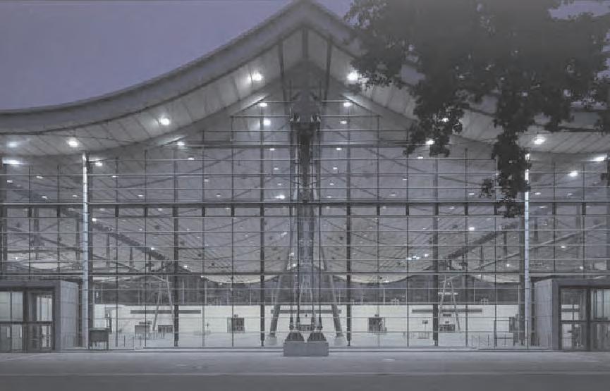
In relation with the program, an exhibition pavilion is an interesting research path, since matches together two issues: Controlled environments and large open spaces inhabited by people. This leads to the conceptualization of what are the implications underlying in a building of this type. Later on, the program for the building will have a key role in the definition of the hypothetical location.
Trade is change. Trade fairs are markets. Markets develop where trade routes intersect. Market rights have always established at such intersections, and still are. As boats become sturdier, coastal trade extends human contact and promotes wealth.
References Hall 8 EXPO 2000 Hanover
Relation with own project
Association between strategies of air movement by the use of low pressure zones, activated by the environment where the building is placed
C_2.1.2 045
Big open space with thermally isolated facade by double glazing.
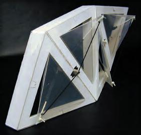
Relation with own project
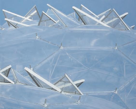
Local scale: Reference of similarities in transparency and ventilation devices (porosities).
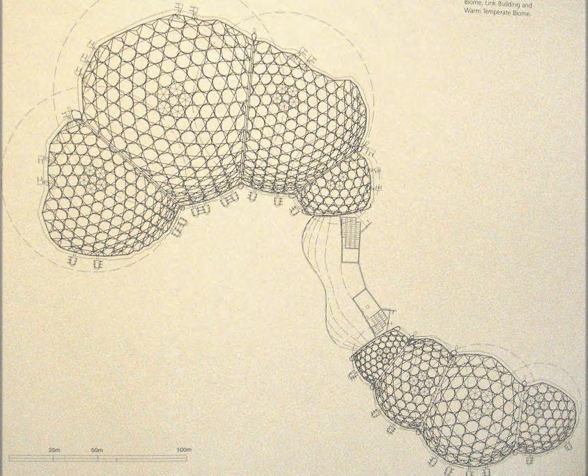
Translucency + climatic control + materiality + global geometry + tessellation
Architect: Nicholas Grimshaw
The team headed by Grimshaw and partners included architects, engineers, botanists and scientists among other specialists. Initially the site is analyzed to determinate the best position and sizes for the green houses in accordance to computer simulations of the sun path trough the year, to identify the best sun exposure. The overall layout of the building is defined by analog models of planar bubbles organizations. The bubbles later are designed as a series of interconnected geodesic domes. The pieces of the domes where constructed using CAD/CAM production processes. The biggest of the domes is 240m long, 55m high and 110m across. The overall area is 15.590m2. The domes panels are glazed with ethyltetrafluroethylene (EFTFE), which is a high techtransparent foil that:
_Is less than 1%of the weight of equivalent glass
_Lets through 98% of sunlight (glass lets through about 90%)
_Has non stick properties (easy to clean)
_Is tough and not degraded by sunlight
_Suffer minimal deformation when it is windy (glass can eventually crack under high winds)
Each panel is sandwich of three or four layers of ETFE heat welded together. After the panels are installed, they are pumped up with dry air. The overall thickness is about two meters, which gives better insulation than normal double glazing.
Climatic control in the domes is maintained by having good insulation to conserve the heat. The domes haves a back wall of natural rock that acts as a heat sink, absorbing heat in the day and giving it off at night. There is also a combined heat and power unit to heat the domes as necessary. Also the rain water is collected and reused, as overhead water sprays simulating rainstorms along with a permanent waterfall to maintain the level of humidity.
Eden is a very interesting project in the research context of this thesis. The more important issues observed are: the technologies used on the construction, form finding processes, materiality and the climatic control system of the building. Nevertheless the thesis look at it just as reference and aims to develop a more sophisticated and simpler way of controlling the conditions at the inside of the building, using the changing environment as informing entity . On the other hand this research aims to develop a system to be inhabited by people not by plants.
Global scale: Form finding processes driven by pneumatic principles in both buildings.
References Eden project
C_2.1.1 046


References
Retractable roof at Rothembaum
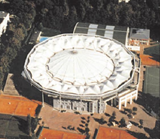
Dynamic behaviour + relation between lock/unlock parts of the system + materiality + size + program
Architect
Werner Sobek
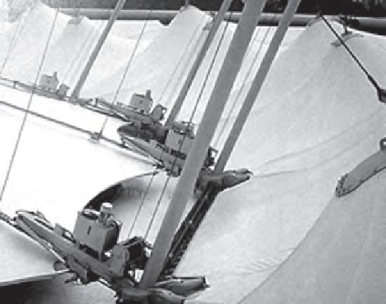
This roof is selected as an important reference due to the dramatic changes of permeability that perform between the two main different states. It is also a clear example to the issue exposed in experiment set 7, addressing the dependency of any dynamic part to a steady structure. Here the relation is very comprehensible where a fixed perimeters works as a support for the retractable roof.
On the other hand, until some extend the program for this roof and its size is suitable to the potentials programs that the system developed in this thesis aims to address. Also the light materiality and the production technologies can be suggested as a potential input to the design.
On the low side this building is an interesting example on readjustment to changes in the environments, nevertheless by no means the project devepoped in this thesis intents to use mechanic systems (such as engines) to activates the dynamic devices.

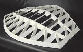
“addressing the dependency of any dynamic part to a steady structure. Here the relation is very comprehensible where a fixed perimeters works as a support for the retractable roof”
Two stages of the roof, sealed and fully open. Relation with own project, experiment set 7.
C_2.1.3 047
Detail and section showing relations between lock and dynamic elements in the building
Controlled transparency / opacity + number of components + parametric design
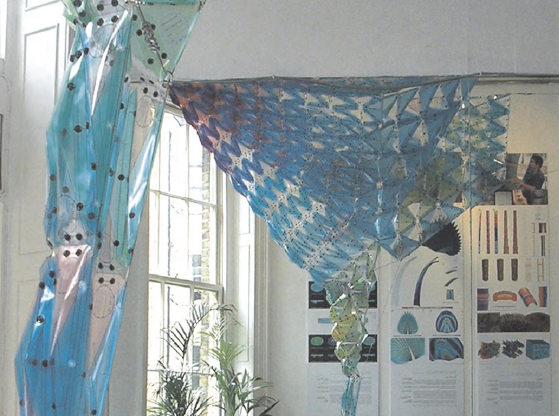
As every year the Emergent Technologies program, prepared an installation in the context of the AA final year exhibition. In this occasion the EmTech group approached the project from the environmental conditions at the room. Where the light pattern at the time of the exhibition (summer) is taken as the most substantial environmental agent to work with.
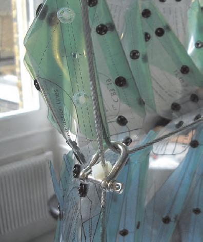
Therefore, the installation will be the design and construction of a day light filter. With this aim, a form founded cable structure is placed towards the light influx zone of the AA Bar, this structure is later populated with over 800 components. Due to their parametric logic, each of the components is different, and each of them has a particular position in the structure.
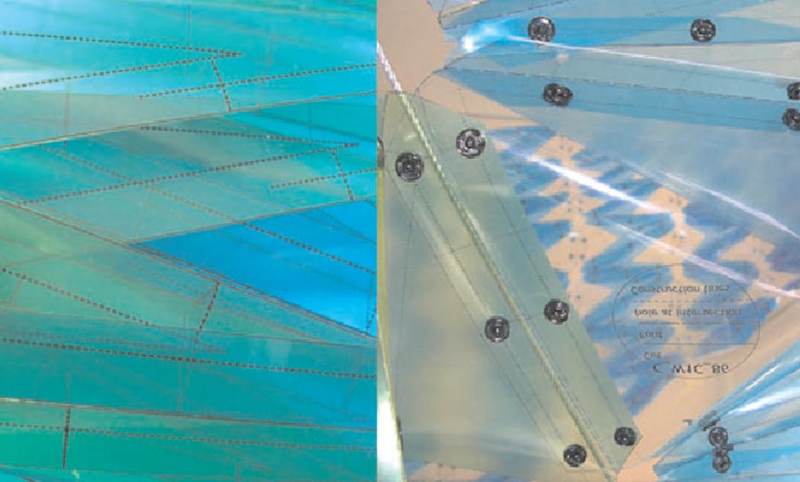
The final product is a highly differentiated light filter, where sizes, shapes and colors are changing smoothly through the surface in relation to their position on it. This procedure is informed in accordance to light conditions at specific points of the surface.
This experience it is very important as it is the first real parametric construction where I have been personally involve, therefore the experience informed the later development of this thesis, where some of the same issues were revisited. Some of them are, design concept, light control, number of components and production techniques.
“highly differentiated light filter, where sizes, shapes and colors are changing smoothly through the surface in relation to their position on it”
References
Parametric day light filter EmTech ex.04/05 AA bar
C_2.1.4
Surface populated with parametric component defined by light exposure and global geometry
048
Details of cable structure where the components where attached, and translucency features of the components
Selected profile
1c+2c+3c+4c+5a
The selected profile is the one that better suits the material system developed. In this range, we can find applications for large open spaces inhabited by people. The applications can be: Sport arenas, exhibition pavilions and shelters in general (train stations, bus stations, gas stations). Since those types of constructions are usually re-thought in accordance to new necessities, materials and technologies, their defined life span is about 50 years. From a structural point of view, the system is “light” in relation to its size, nevertheless it has to be strong enough to support it self and the forces transmitted by the environment, such as wind and water.
1_Structure capacities
1a_Self support
1b_Low weights
1c_High loads
1d_Heavy loads
1a+2a+2b+3a+4a+5b+5c
The mixed profile in this case gives a very light structure, highly susceptible to environmental conditions, with the tendency to be relatively small in size. These kinds of bodies are designed with the acknowledgement that they have to last for a very short period of time. On the other hand, they have limited capacities of reconfiguration.
1b+2a+2b+3a+3b+4a+4b+5a+5b+5c
The mixed profile in this case gives a structure, or a system, with the size to allow human activities. Due to the lightness of the structure, this configuration is still susceptible and influenced by the environment: in its structural capacities and also during the design process. The structures can be much bigger but still they have limitation in its size. The life span in most of the cases is short since the designs are constantly changing with the technologies and tendencies. The dynamic behaviour can be either present or not.
1c+2c+3c+4c+5a
The selected profile is the one that better suits the material system developed. In this range, we can find applications for large open spaces inhabited by people. The applications can be: Sport arenas, exhibition pavilions and shelters in general (train stations, bus stations, gas stations). Since those types of constructions are usually re-thought in accordance to new necessities, materials and technologies, their defined life span is about 50 years. From a structural point of view, the system is “light” in relation to its size, nevertheless it has to be strong enough to support it self and the forces transmitted by the environment, such as wind and water.
1d+3c+4c+5b+5c
The heavy structures are in most of the cases the result of accurate mathematics and physics calculation that give to the engineers the ideal shape, form or configuration of a specific type of material in relation with a predefined purpose. Thus the environmental factors are part of the equation. In this category, we can find the biggest structures achieved by architects and they are building made to last for a very long period of time. In relation with the dynamic behaviour, they can have intricate mechanisms in order to make this systems perform in complex ways.
Performance Envelope
2_Environment 2a_Geographic 2b_Weather/climatic 2C_Relation int. ext. 3_Scale/size 3a_Small size 3b_Medium size 3c_Large size 4_Life span 4a_Temporary 4b_Short 4c_Long 5_Dynamic behaviour 5a_Passive 60% 5b_Activated 30% 5c_Static 10%
C_2.2 049
Passive environmental control in conventional buildings
Standard wind forces behaviour at building.
Side and plan view
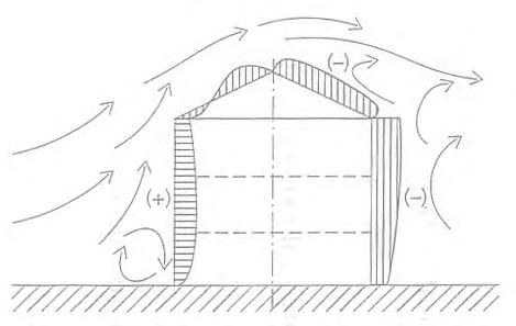
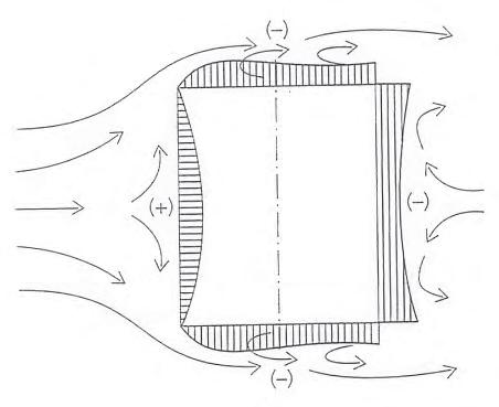
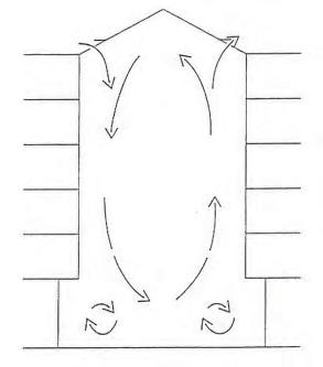
Diagram of air movement for natural ventilation and different temperature gradients and influx velocities
Low velocity_ 0.5 m/s Medium velocity_ 2.5 m/s High velocity_ 5 m/s
Isotherm
Outside colder than inside
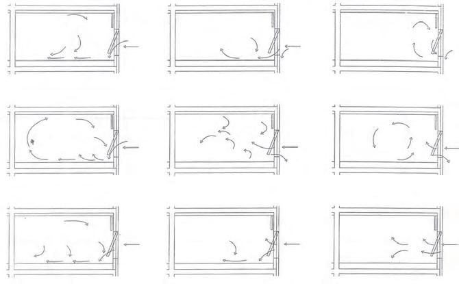
Outside warmer than inside
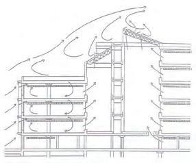
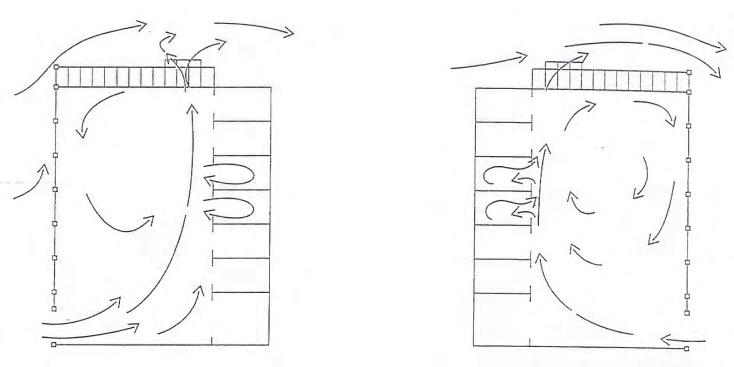
Variations of wind flows affected by building shapes

Variations of wind flows affected by building orientation
In the pursuit for natural ventilation in buildings, it is important to consider some factors such us: Size of the space intended to be ventilated, wind forces at the site, frequency of calms (no wind), emissions and thermal properties in the room.
The first thing to do is to evaluate whether or not the site is suited to place a building with natural ventilation, therefore measurements of wind forces, frequency and prevalent wind directions to which the building is exposed are essential. It is also important to establish if emissions present at the site may prevent natural ventilation or whether dust, noise, odors and other factors may limit the degree to which natural ventilation is useful. In relation to the spaces suitable for natural ventilation it is important to have a relation between size of the room and exposure to wind forces. On the other hand wind penetration and air currents in to the room change both in response to the relation of outside and inside temperatures. Another factor to consider is the percentage of openings as windows. Regarding this, the faster the wind flows, the smaller the percentage of openings. Any wind flow over 5m/s is enough to have a partial opening.
In the case of large open spaces it is possible to generate a high degree of air influx by the proper use of the façade. This can be complemented by creating shafts (stacks) in the interior of the building, which generate strong negative pressure in the area beneath the roof, thereby producing a suction effect that ventilates the building. The same effect can be achieved promoting negative pressure above the roof trough the specific geometry of the building. When differences between inside and outside temperatures are sufficiently high, the interior is naturally ventilated even in periods of low wind velocity. Air change is only achieved, however, when the outside air is colder than the air on the inside. When isothermal conditions exist, air movement can not be achieved during periods when there is no wind.
“Another factor to consider is the percentage of openings as windows. Regarding this, the faster the wind flows, the smaller the percentage of openings”
“generate strong negative pressure in the area beneath the roof, thereby producing a suction effect that ventilates the building”
Fluid Dynamics
C_2.3 050
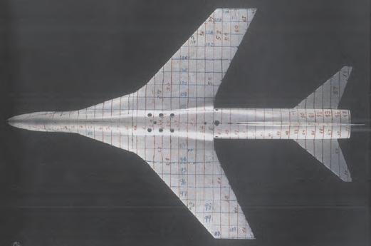
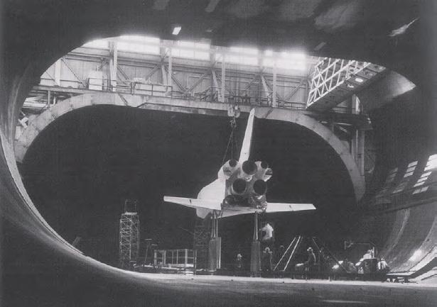
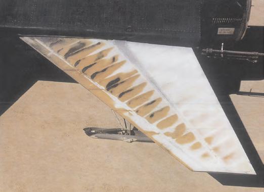
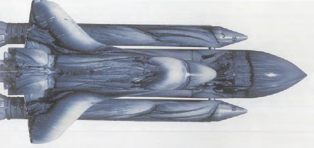
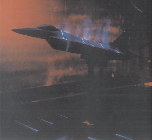
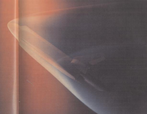
Analog fluid dynamics simulations
1_This model of modified F-8 (1968) was used for supercritical wing research. It displays several of the innovations used to achieve supersonic speeds, including the area rule (evident in the pinching of the fuselage) and the supercritical airfoil, both developed at NASA by Richard Whitcomb. This model was specifically used to study the supercritical wing at speeds near Mach 1. The markings on this model represent reference measurements, used to determine the cross-sectional area and model volume.
2_This horizontal stabilizer on an x-15 was painted with thermally sensitive paint. As the airplane got hotter, the painted surfaces turned different colors. This visually shows the heat gained by various surfaces. The white areas are relatively cool, while the brownish areas were hot.
3_The air flow around a model of the F-16XL is seen using smoke and laser light sheet during a wind tunnel test in NASA (1993). Lasers are used to visualize the flow of air over the model. These techniques are used to analyze the flow field around the airplane before proceeding to flight-test.
4_A 1/3 scale model of the final Space Shuttle configuration tested in a 12x24 meter wind tunnel. The model was 13.38 meters long, and was used for low-speed data in support of the approach and landing tests.
5_An oil flow study of the Space Shuttle launch vehicle showing the localized flow patterns over the vehicle when is traveling at March 1.96. A mixture of oil ant paint is applied to the model. When the wind tunnel test is completed, light colors or lack of paint denote high pressure regions, while dark blue colors or heavy concentrations of paint show low pressure or stagnation regions.
6_The flow field around a model of the Space Shuttle orbiter is visible at Mach 20 and 35 degrees angle of attack. An electron beam illuminates the flow around the orbiter 56cm. model at NASA Langley Research Center Hypersonic Helium Facility. The variations of colors and brightness graphically depict the flow around the vehicle.
Fluid Dynamics
1 2 3 4 5 6 051
Environmental Context
Climatic zones
Suitable types of weather
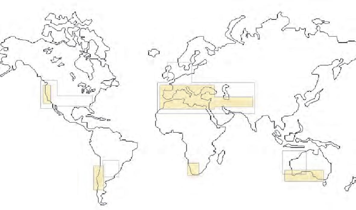
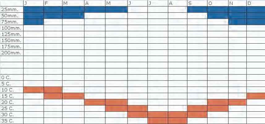
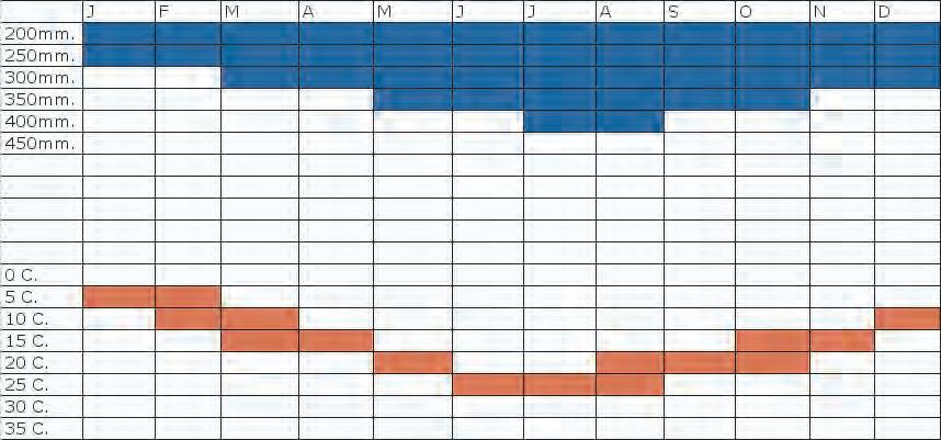
The climate system
The earth’s climate system is a highly complex interactive system involving the atmosphere, hydrosphere (oceans, lake and rivers), biosphere (the earth’s living resources), cryosphere (particularly sea ice and polar ice caps) and lithosphere (the earth’s crust and upper mantle). This results in a great variety of climates types.
Mayor climatic regions and sub-types
Polar: Ice cap, tundra.
Cooler humid: Subarctic, continental cool summer, continental warm summer.
Warmer humid: Temperate, humid subtropical, Mediterranean.
Dry: Steppe, desert.
Tropical humid: Savannah, rain forest.
The climates considered more suitable to test the material system developed are the ones defined as warmer humid, and more specifically Mediterranean. Nevertheless Temperate zones are considered as potential locations aswell.
Mediterranean weather description
A Mediterranean climate is one that resembles those of lands bordering the Mediterranean Sea. It is usually experienced between 30 to 50 degrees north and 30 to 40 degrees south of the Equator. In zones of Mediterranean climate, rainfall results almost entirely from the procession of the westerly zone of frontal storms during the low-sun season; during the summer, the subtropical high-pressure zone dominates the seasonal weather, preventing rainfall by preventing rainstorms from forming. Mediterranean climates are generally pole ward of the great dry belt of subtropical deserts but equator ward of the zone of maritime temperate climates. They are never on the east coasts of continents. Because of the proximity to large bodies of water, temperatures are generally moderate with a comparatively small range of temperatures between the winter low and summer high. Temperatures during winter rarely reach freezing, and snow is almost unheard of. In the summer, the temperatures, while warm, don’t reach the high levels of inland desert areas. The average temperature for most places experiencing this climate is 8 degrees Celsius in winter and 27 degrees Celsius in summer. The subtropical western coasts of continental landmasses typically experience such climates. Examples include Coastal California, Western Australia, Cape Province in South Africa, and central Chile. Inland locations sheltered from (or distant to) sea breezes, experience severe heat during the summer characteristics of hot deserts.
Athenas climatic chart _ Mediterranean London climatic chart _ Temperate C_2.4.1 052
Location of Mediterranean and Temperate climatic zones in the world
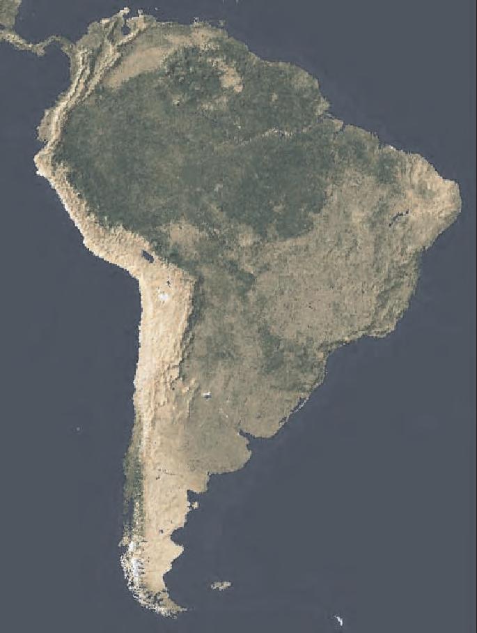
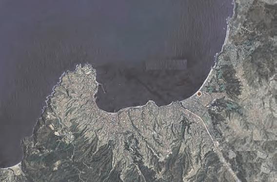
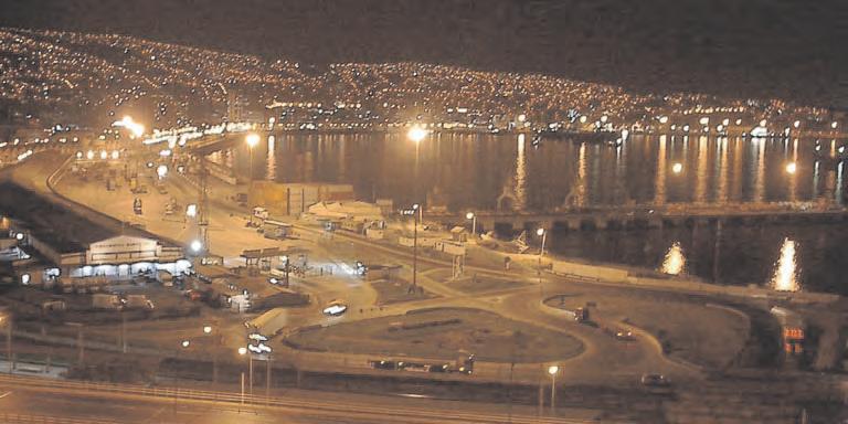
Winds associated with precipitation
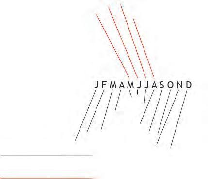
Environmental Context
About the location and the program
Valparaiso, Chile Latitude_ 33.2S Longitude_ 71.40W
The hypothetical location of the building is Valparaiso, a city in the central Chile coast, where the climate is Mediterranean and during the summer the wind blows steadily from the south.
In relation to the location and program, historically, Valparaiso used to be one of the major ports in the Pacific Ocean, since the only pass between the Pacific and Atlantic oceans was the Estrecho de Magallanes. When the Panama channel was build at the beginning of the last century the history and destiny of Valparaiso where lost. This project aims to reinforce the historic position of the city as a trade point. Therefore the hypothetical structure is an exhibition pavilion located in the former harbor areas.
Summary of climatic conditions in the costal zone of central Chile:
Average temperature summer 20 degrees Celsius
Average temperature winter 15 degrees Celsius
The average fluctuation of temperature between day and night is: 5 degrees Celsius
The relative humidity of the air is: 65%
The average annual precipitation is: 462mm. concentrated between the months of June and October
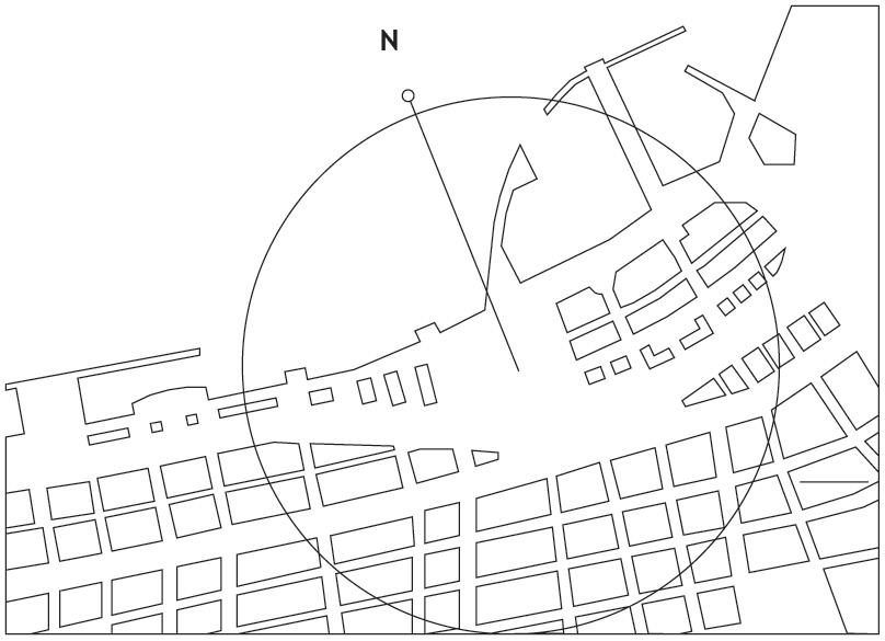
Wind Chart
Speed scale 10m/s
N S N N C_2.4.2 053
Site Plan View

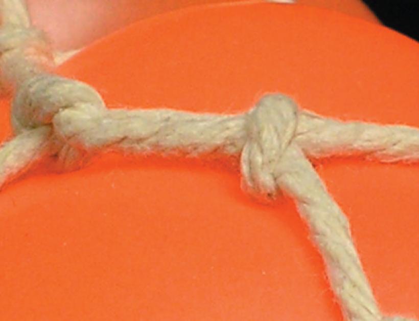
Global to local
Pneumatics Form Finding experiments informing parametric definition for global shape
Until now the material system has been developed from isolated experiments at local and regional scales. Thus, there are not any suggestion of how the components will be proliferated and what kind of surface or structure will host them. Also the sets of experiment undertaken are suggesting the directions towards a global shape definition.
Since the material system is keen to be implemented in grid shell structures, the same pneumatic background is taken as a valid and instrumental input to deal with the global geometric definition. On the other hand these types of shapes are characterized by their smoothness and continuity; therefore they can generate different pressure zones with out changing dramatically the natural wind flows at their surrounding. This is a key fact in the pursuit of a passive ventilation system.
“these types of shapes are characterized by their smoothness and continuity; therefore they can generate different pressure zones with out changing dramatically the natural wind flows at their surrounding”
Parametric Design Engines
C_2.5.1
Global geometry shaped by pneumatic forces and controlled by fixed frame and lines, describing a particular tesselation of irregular domes.
054
Examples of curvature in surfaces at local scale defined by rigid control lines.
Informed by the pneumatic experiments exposed before, a series of parametric models where done. Their logic is deduced from relations between the arches in the XY plane, or steady parts (in relation with the bases of the analog models), and the arches perpendicular to the XY plane. The curvature of these arches is defined by measurements on analog models, and their relations are maintained constant to parametric modifications. Thus the manipulation of the control points is affecting the arches in XY plane and the perpendicular ones aswell keeping the parametric relations stable. Each of these models has a different parametric set up but they are all controlled by the same rules. Their geometry is constructed in Generative Components where only the structural arches are defined; this decision is taken to endorse the fact that they are fixed geometric entities; these entities will lately rule the surfaces. The output from GC is taken into Rhino where the surfaces are constructed by lofting particular combination of arches.
1_Geometry ruled by cross-section with normal angle in relation of the points describing the primary arch. All the zones are framed in 3 sided patches and some of them are opened to the side at ground level.
2_Series of 3 different vertical boundary lines outputs for the same configuration of horizontal control points. Multiple 4 and 3 sided patches. In the case of model “B” there is some gaps/openings between 4 sided and 3 sided patches.
3_The output of this test is more smooth and continuous since the vertical sections are described as a single arch instead of a double one. There are also connections between 3 and 4 sided patches
4_Geometry described by several (18) control points, the vertical arches are described as cross sections between alternate points of both sides. In the zones where the volume growths the connections between control points increases as well
Design Engines Global to local 1 Parametric design evolution 2a 2b 2c 3 4
Parametric
055
Coordinate system
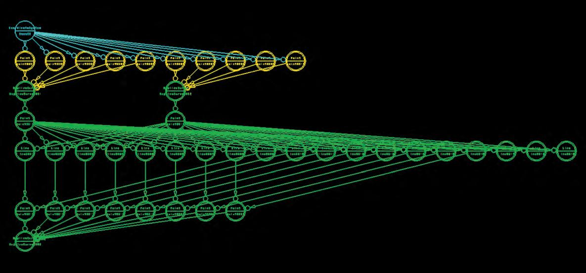
Parametric Design Engines
Global to local
Control points
Ruling bsplines 1 and 2
Collection of points in bsplines
Relationship between points
Generative Components global geometry model
Construction logic, relation between symbolic and geometry models
Vertical lines from intersections
Ruling bsplines 3
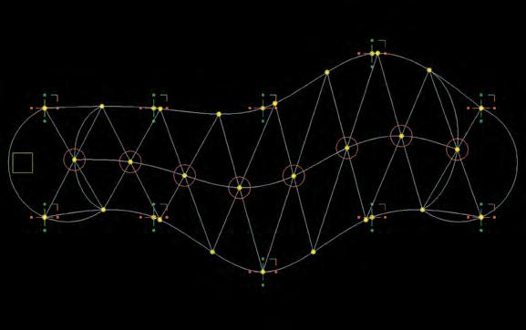
Vertical lines from intersections Control points
The same logic used during the design process described before, is applied to define a final parametric model for the global shape. In this case the parametric relations in the model are more complex, however the final output -or shapes- are simpler and smoother. The reason for this, is that at this point of the investigation is evident the role played by the environment, where wind, light and water needs to be strategically manipulated to use them like actuators on the climatic control system of the building. Therefore with out quitting the principles implicit in the pneumatic form finding experiments, this parametric model is designed to create smooth surfaces where the elements flows and the cast of them is more predictable, making their strategic combination easier without adding extra complexity to the task. One good example is the “wing like shape” of the geometries; this will secure the acceleration of winds and describe specific areas of pressure over the surface.
Relationship between points
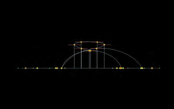
Ruling bsplines 3
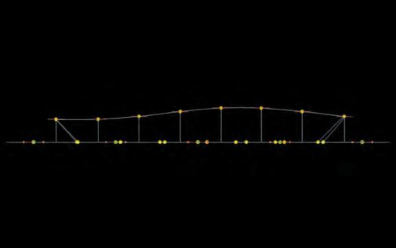
Relationship between points
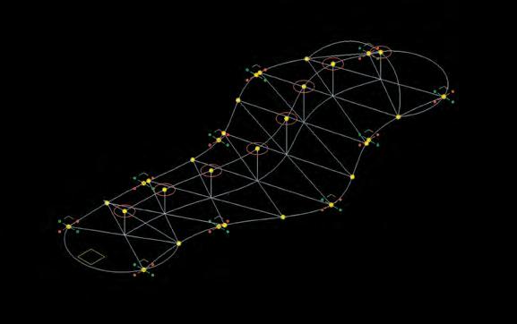
Ruling bsplines 1 and 2
These decisions are taken considering the characteristics of the site selected to insert the sample building. Where the exposure to winds, sun light and water are forecasted in accordance to the characteristics of Mediterranean weather and specific meteorological data extracted for Valparaiso city.
“this parametric model is designed to create smooth surfaces where the elements flows and the cast of them is more predictable. One good example is the “wing like shape” of the geometries; this will secure the acceleration of winds and describe specific areas of pressure over the surface”
Symbolic view
056
Plan view front view Side view
Isometric
The geometry of the parametric model is controlled by ten control points, five for each of the two original bsplines. This action will deform the bsplines in the XY plane, each bspline is divided in eight sections made by a series of points (0,1,0.25). Each of these points is interconnected with the two diagonally opposite pair of points, what gives a series of intersections between the two initial bsplines. From there, a vertical line is defined. The length of this line is the addition of the distances between the four points defining the two lines that intersect at the starting point of the vertical line ((Distance(point1,point2)+Distance(point3,point4))*0.125). Using the 8 points at the end of each vertical line, the third bspline is constructed. Finally the geometry is closed by two arches at each end of the three ruling bsplines. As the model is activated, the relations remain constant, and the global shape readjusts to external manipulations of the control points, keeping the smooth relation between width and height.
This particular model does not consider the possibility of been inserted in non-flat terrains (since bsplines 1 and 2 only operates in XY plane in order to secure intersection between the lines). Since at this point of the investigation the site is been already defined (horizontal ground), this issue is not considered. This limits the insertion of the building into more complex terrain configurations. Nonetheless it is not difficult to make the adjustment in order to improve the model in that way. Besides this fact is by no means an impediment to successfully continue with the thesis development, and there are not practical reasons to consider the update at this state of the investigation.
Design Engines Global to local Operation logic 1 Original configuration 2 Control points 3 Horizontal splines 4 Negotiators between distances of splines
Points describing central spline, or building back
Vertical distance output
Skeleton from where the final shape is extracted.
Parametric
6
5
7
Two stages of global re-configuration. Top Side Perspective Front Top Side Perspective Front 057
Samples superposition
Global to local Y axis variations of control points, volume increase.
Series of samples extracted from parametric manipulations
X and Y axis variations of control points, volume decrease.
Starting from the most regular possible configuration, a series of nine different outputs where extracted from the parametric model. During this procedure the complexity of the shapes increases gradually as more control points are manipulated. The first series of six variations is defined by the manipulation of the points in the Y axis and the gradual increase in the overall volume of the samples. The second series of two variations is defined by manipulation of the control points in Y and X axis and the gradual decrease in the overall volume of the samples.
The two series then are taken into Rhino where the surfaces are constructed in accordance to the definition of the ruling bsplines. After this process the parametric engine proved a successful performance, since all the surfaces extracted from it are within the restriction of smoothness and continuity previously defined. However, only one will be selected according to parameters defined by the interaction between inductive and deductive procedures in global and in local scales, together with environmental conditions at the site.
“all the surfaces extracted from it are within the restriction of smoothness and continuity previously defined”
Engines
Parametric Design
Top Perspective Front Side
Plan Perspective Front Side 058
Exposure to environmental inputs
The first step in order to observe the interaction of the surfaces created with environment, is to expose them to parallel horizontal influence. This operation is performed using the render application in VectorWorks, where all the samples where exposed to the same setting (4 different exposures to each of them). The output from this process is the first set of observations of the surfaces under the influence of wind and light. From this procedure early notes were extracted, defining which of the shapes is more adequate to take it into further and more specific sets of simulations.
“this process is the first set of observations of the surfaces under the influence of wind and light”
0 degrees 90 degrees 180 degrees 270 degrees Parametric Design Engines Global to local
059
Triangle lines 2
Triangle lines 3
Frames
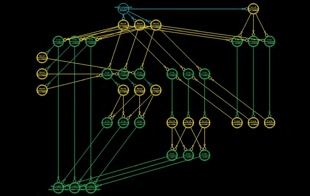
Symbolic view
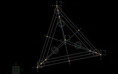
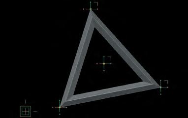
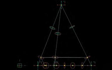

Direction lines
Local to global
Porosity points
Generatives Components local geometry model. Construction logic, relation between symbolic and geometry models.
Triangle lines 1
From the sets of analog experiments linked to the material system, the four sided component is dismissed in favor of the triangular one. The reasons for taking this path is, on the one hand because of the better and simpler interaction between triangular components and pneumatic devices, and on the other hand because the system is already defined as a gridshell organization, consequently triangular tessellations suits better this kind of structural configuration. Thus, the particular characteristic of the four sided component of operate in a collective manner in order to achieve articulations between cells (and therefore bigger openings), is replaced by the isolated activation of many triangular porosities that collectively operates major changes in the envelope permeability.
As is been described in the analog experiments the triangular component is defined by four input points, one for each angle and another one that supply directionality and thickness to the frame. Apart from that simple description the component is more complex. From each of the vertices of the triangle, a line is defined towards the centre of the opposite line. In each of the new lines created, a point is placed with a “T” value; the movement of this point along the line will later define the degree of opening of each cell. This is controlled with a global variable, which defines three different positions of the points along the line resulting in three different levels of opening. In order to create the surfaces to construct the frame, three different triangles were formed, one between the lines going from the angles of the triangle towards the external control point, another between the points that controls the degree of opening and the last one by the actual vertices of the component. These three triangles are lofted, resulting then in a triangular frame.
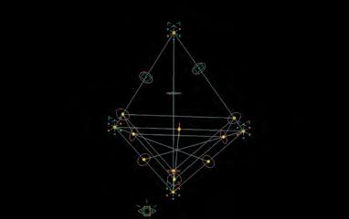
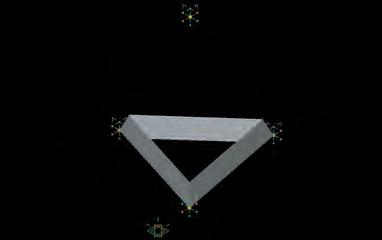
“The reasons for taking this path is, on the one hand because of the better and simpler interaction between triangular components and pneumatic devices, and on the other hand because the system is already defined as a gridshell organization, consequently triangular tessellations suits better this kind of structural configuration”
Parametric Design Engines
C_2.5.2
Triangle vertices External point
Construction lines imbedded in component
060
Volumetric out from construction lines

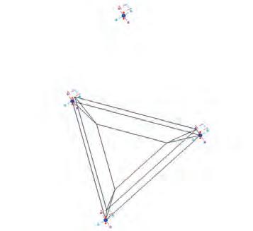
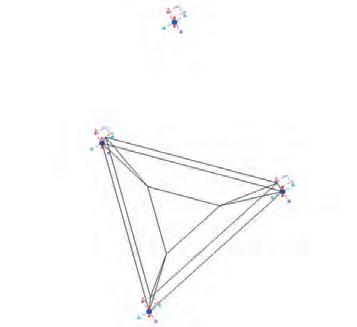
Series of opening settings, controlled by a “global variable”

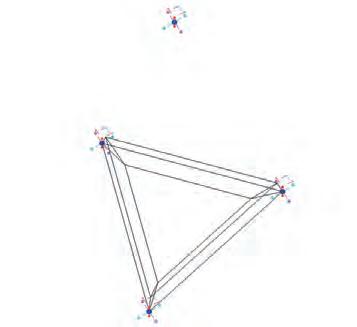
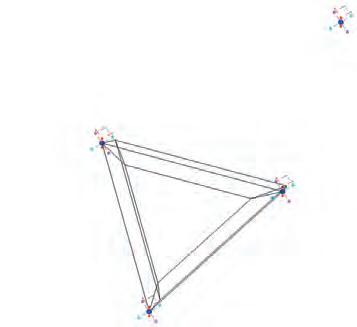
Series of modification of the shape by manipulation of control points.
First concept of porosities activated by a pneumatic device, in this early model is difficult to achieve and control the degree of permeability. In the actual component can be numerically defined.
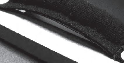

First parametric triangle designed in the context of the material system. At this point the possibility of variable opening was not inserted yet and the frame was conformed by four faces instead of three.
Local scale
A component is the entity that is populated over a tessellated structure; parametrically the component used is one. Nevertheless geometrically speaking, each of the components in the system is potentially unique, and the way in which they are organized over the surface describes a highly differentiated system.
As is been explained previously, the configuration of a single component is controlled by two main devices:
One is related with the size of the porosities and it is controlled by a global variable (In Generative Components, a global variable is a value that can be related to more than one geometrical entity of the model. In this case is affecting the three points that define the size of the opening). The values defined for the global variable are three, and they set the level of transparency of each component.
Value 1 = 75% of opening of the global area of the cell
Value 2 = 50% of opening of the global area of the cell
Value 3 = 25% of opening of the global area of the cell
The other control device defines the external shape of the component and is controlled by four points. They delineate parameters such a size, angles degree at the vertices and thickness of the frame. The possible configurations are infinite and they are all fixed to the parametric relationships seed in the component. In relation to this, the “drawing” of the piece is done with out any kind of scale or unit system, since never mind if the piece measures one centimeter or three meters, the relation between the geometric principles remains constant.
Design Engines
Parametric
Local to global Component parametric features
061
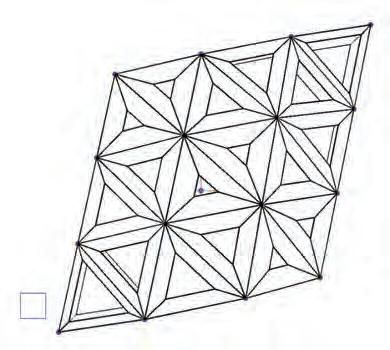
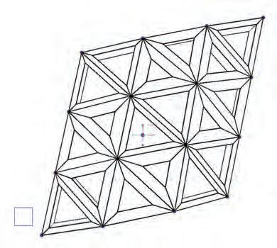
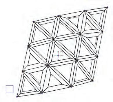

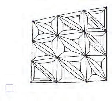
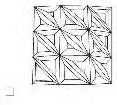
Proliferation of components and patch manipulation in a regional scale
Regional scale
Proliferation of components and light permeability variation in a regional scale

The process of scaling up the component is made with the purpose of investigating and understanding the behaviour of a cluster of members in a regional scale. Therefore a small surface is constructed where 18 triangular triangles are nested; the initial shape for the surface is a rhombus, because this shape allows a configuration where the sides and sizes of the triangles are even. The proliferation process is completed by nesting the components in the surface, and using an additional “external to the surface” input/control point.
The first process of manipulation is conduced by the modification of the surface in the XY plane, switching from the original rhombus to a square, with one intermediate stage. In the first step all the triangles are regular; in the second step all the triangles are different, since the irregularity of the shape. Finally at the third step the triangles are regular again, in this case with two equal sides each. From this simple process we can understand the dependency of the components to the hosting structure. In relation to this, one that the component is nested into the surface, its shape can not be modified individually anymore, now is ruled by the surface.
On the other hand, despite the fact that they are already attached to a bigger hierarchical organization, each individual component can be modified on its degree of opening, thanks to the global variable previously defined. Therefore the same cluster of components is used to analyze four different degrees of overall translucency. Starting from the most open configuration, the cells are gradually closed (starting from the acute angles of the surface towards the middle of the cluster), achieving an overall new level of translucency. Just to give an idea of the high degree of differentiation that can be achieved in a global scale; in this small proliferation there are 18 triangles, each of them has 3 levels of translucency, so only for this patch there are over 54 different configuration, with out considering the infinite additional modifications that can be perform in the hosting surface.
“Just to give an idea of the high degree of differentiation that can be achieved in a global scale; in this small proliferation there are 18 triangles, each of them has 3 levels of translucency, so only for this patch there are over 54 different configuration, with out considering the infinite additional modifications that can be perform in the hosting surface”
Design Engines Local to global Patch parametric features
Parametric
062
Analog model of early triangular proliferation deduced from parametric components.
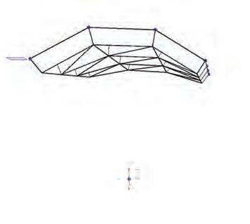
1_Variations of patch trough modification of hosting surface
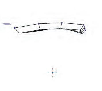
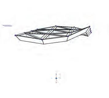
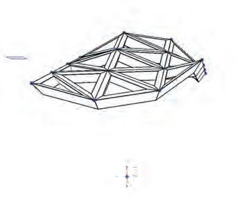

2_Variations of components directionallity by translation of external point trough X axis
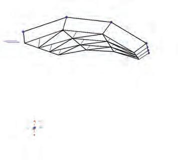
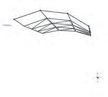

3_Variations of components thickness by translation of external point trough Z axis
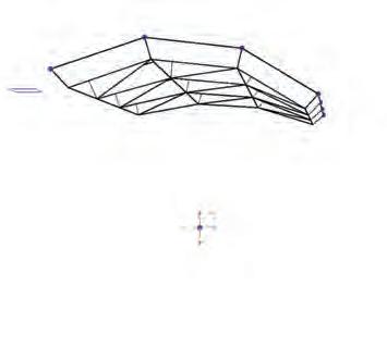
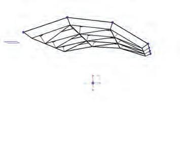
Regional scale
The next series are ruled by 3D modifications of the cluster. The first one is conduced by the actual manipulation of the hosting surface, switching from sinclastic to anticlastic in four different intermediate states. In each of them all the components readjust to the new setup. Other collateral variation to this action can be observed in the change of thickness of the components, since as the surface is taken downwards approaches the “external to the surface” input point shared by all the components, as is been explained before the thickness of the components is proportional to this distance.
The next series of modifications are conduced using the “external to the surface” control point. One of the features achieved with this tool is that this point defines the orientation of all the components (within a determinate section of the global system). Therefore, if an arched organization is designed, the position of this point will determinate the tendency of light permeability in relation with the direction of light influence. This feature is explained with more details later on the conclusive chapter of the thesis. Nevertheless in the series number two can be observed how the lines that are describing the edges of the triangles -therefore the direction of the faces- are following the position of the point.
Finally as is been already said, the translation of the external point in the Z axis will affect the overall thickness of all the components related to this point. This feature can be utilized in an instrumental way, using the position of this point as a way of changing structural capacities of the system. The farthest from the “external to the surface control/input” point the thicker the components gets. In relation to this, the behaviour of the organization can be observed in series three, where the single movement of one point has an overall influence on the thickness of a collection of components.
At this state of the research is important to notify that there is a factor from the global geometric point of view that is not addressed by this investigation. The fact that it is not solve the negotiation between different patches populated by “external to the surface” control/input points. The implications of this affect the perfect match between the patches. In the case of my overall geometry, three major patches are predicted, with consequential two negotiation zones. This procedure is dismissed in favor of the development of other aspects of the system. On the other hand, this issue is been undertaken and solve in the thesis of Daniel Coll I Capdevilla ( AA Dip4 2005) where three sided parametric components where used aswell. Finally is important to state that there are simpler ways to achieve this, and that it is not considered as a key factor for the proper completion of the research.
“The next series of modifications are conduced using the “external to the surface” control point. One of the features achieved with this tool is that this point defines the orientation of all the components”
Parametric Design Engines Local to global Patch parametric features
Two states of a larger parametric patch informed by surface manipulation 063
UV_Grid_18x60
Overall Components_2006
UV_Grid_12x40
Overall Components_858
UV_Grid_9x30
Overall Components_464
UV_Grid_6x20
Overall Components_190
Melting of scales Uniform Tessellation degree
At this state of the research, the definition process became very specific, therefore is imperative to combine and melt the parameters investigated in global and local scales in order to move towards more advanced environmental tests. Firstly the definition process is until some extent intuitive, on the other hand is a highly informed by the actual state of the investigation; as it will be explained further in the initial part of the next chapter.
After revising the global and local design processes, the investigation focus on the combination of these two procedures. The global geometry is taken from the final stage of the “global to local” design engine, after an early environmental exposure method. This geometry is subdivided in triangles, which secure the definition of the shape by flat sections. Four different levels of uniform tessellation are suggested and two of them are defined as the more suitable ones (858 and 464 components each), firstly because of the degree of differentiation intended to achieve with the system and secondly in relation with the size of the components and the ability to insert them in real constructions processes (CAD/CAM). Also the setting of the tessellation will define the sizes of the porosities and therefore will determinate the weight that the pneumatic devices will take.
Plan Side Front Plan Side Perspective Front
Design Engines
C_2.5.3
Parametric
064
Series of 7 different non uniform overall tesselation variations. The degree of tesselation is defined by the amount of curvature in different regions of the surface.
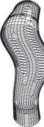




Parametric Design Engines
Melting of scales Non_uniform
Differential description of the surface
As another way to describe the global geometry, this process leads to a more differentiated description of the envelope. The procedure is conduced by setting different levels of accuracy for polygonal deduction of the surface, as the parameters of the geometric definition are manipulated the tessellation degree change. What remains consistence is the agglomeration of geometrical entities (lines and planes) in the areas with more curvature (where more information is required). Therefore the technique defines the overall level of definition, organizing the geometrical information trough the surface adding more where is required, and less where is redundant.
As is show below seven manipulations of the geometric information where made, with one output for each. From this sets two where extracted in accordance to the most suitable tessellation degree defined previously.
“Therefore the technique defines the overall level of definition, organizing the geometrical information trough the surface adding more where is required, and less where is redundant”


Plan Side Perspective Front Plan Side Perspective Front
065

At this point of the research, the global geometry is associated with the environment and its influence. This is done using computer simulations of the environmental conditions of wind and light at the location. The first procedure done is the one that simulates the wind flow patterns at the site, by using computer fluid dynamic (CFD). The aim for this task is to use the pressure and gradient mappings over the surface and extract from there information to define population and permeability logics.
To make the wind flow simulations the first duty is to model the volume of air surrounding the building, the aim is to generate a close volume. This volume has to be perfectly modeled in order to be understood by the simulation software (Ansys). The first step is done by taking the same bsplines used to create the shape of the building and project their end points into the box defined as the volume. This procedure demarcates the segmentation of the volume in 21 zones. (16 for the building and ground floor level + four sides and top plane of the box). In order to do this, the bsplines are extracted from the GC model; they are exported as IGS into Rhino, where the volume of air and the segmentations are define.
“To make the wind flow simulations the first duty is to model the volume of air surrounding the building, the aim is to generate a close volume”
Environment Cast in Building Wind flow simulations Geometry
B_splines from GC Top Side Front Stage 1 Stage 2 Stage 3 C_2.6.1.1
preparation for CFD
Z_1 Z 2 Z 3 Z 4 Z 5 Z 6 Z 7 Z 8 Z 10 Z_11 Z_12 Z_13 Z_14 Z_15 Z_16 Z 9 066
Geometry preparation for CFD Bi rail surface construction in Maya
The lines describing the different zones are taken into Maya where they are lofted into surfaces that share the same amount of subdivisions. This fact is very important since will secure the proper unification of the patches. This process is made with a high level of definition, where each of the 16 patches at building level -the ones with more complexity/geometrical information- is described with over 1250 triangular geometric entities.
Side Front Stage 1 Stage 2 Stage 3
Wind
Environment Cast in Building
flow simulations
067


Finally, the different surfaces are merged together; the output is one continuous volume resembling the negative of the building shape. This volume represents the volume of the air affected by the building shape.
In order to run the simulations the final geometry of this process is imported as IGS into Ansys. There are defined the final factors that will determinate the digital simulations, such as influx / outflux faces and wind velocity.
“the output is one continuous volume resembling the negative of the building shape. This volume represents the volume of the air affected by the building shape”
Wind flow simulations Top Side Front Stage 1 Stage 2 Stage 3
Surface merged in Maya
Environment Cast in Building
Geometry preparation for CFD
068
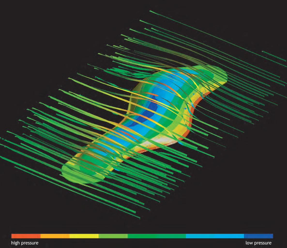
Pressure map at surface level in accordance to predomi-

Ansys is the software used for the analysis and simulations shown here. For simulation, Ansys Multiphysics is the most comprehensive software; a coupled physics “engine” that provides the ability to construct and run simulations for structural, thermal, fluid dynamics, acoustic and electromagnetic analysis. In our experiments we have used Ansys Workbench to simulate the wind flow patterns and pressure developing on the building envelope at different times of the year. The careful analysis of the wind flow patterns and pressures on the building envelope produced by the simulations is used to develop a strategy for controlling the localized facade components in a coordinated way, so that the site’s wind characteristics are used for the purpose of natural ventilation and passive environmental modulation.
Setting up the simulation requires two sets of data, on the one hand gathering and analyzing meteorological information for the site and the predominant wind speeds and their directionality, and in the other hand producing three-dimensional models of the building and the surrounding topography, natural and built, within a region of approximately half a kilometer.
Text by Michael Weinstock with Nikolaos Stathopoulos for AD Magazine edition March 2006.
According to predominant wind flows direction and taking a speed of 10m/s in accordance to information gathered for the site, two main sets of experiments where made. The first one is associated only to the building envelope, while the second one involves the surrounding environment aswell.
The first -and easier to read- image on the left, shows the mapping of the pressure zones over the building surface in accordance to the influx zone. The area of the surface with a higher pressure is the red one, and is located in the windward lower part of the building at the union with the ground level. The “wing like” shape of the building generates acceleration of the flow at the top of the envelope, defining there the lowest pressure zone. Between these two zones (lowest and highest pressure) the transitions of the pressure trough the surface is rather smooth, without dramatic changes of pressure in short areas of the envelope.
To contextualize the concepts implicit in some of the images Bernoulli’s principle is described:
Bernoulli’s equation states that in fluid flows, an increase in velocity occurs simultaneously with decrease in pressure. Also states that the sum of all forms of energy in a fluid flowing along an enclosed path is the same at any two points in that path. Is only important to note aswell that the only because of the change in fluid velocity is the difference in pressures either side of it.
“The “wing like” shape of the building generates acceleration of the flow at the top of the envelope, defining there the lowest pressure zone”
Environment Cast in Building Wind flow simulations Mappings
C_2.6.1.2
069

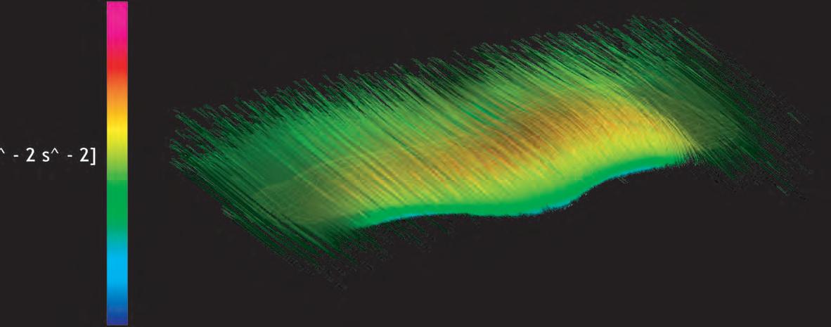
The concept of “gradient” is used in several scientific applications and therefore many definitions can be applied to the term. A generalization of these concepts is the gradient in vector calculus. The gradient of a scalar field is a vector field which points in the direction of the greatest rate of increase of the scalar field, and whose magnitude is the greatest rate of change. For example, “pressure gradient” is defined as the change in pressure over a distance.

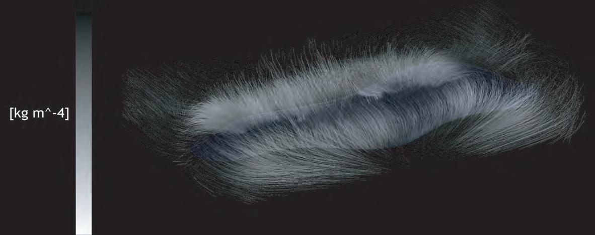
By analyzing the images on the left it can be observed the interrelations between different kinds of mappings for the same wind flow pattern, and how it is affected by the building shape. On the top image is clear how the vectors move towards the highest pressure zone (windward lowest part of the envelope). Where the blue/green colors are in opposition with reds vectors over the top of the building.
In the case of the second and third images, they are both referring to the air volume surrounding the building. They can be clearly related one with the other. Therefore a parallel can be established between air density and wind velocity, where a decrease on density is translated on an increase of velocity. This is shown by the equal configuration of gradient vectors trough the volume of air surrounding the building envelope. In the last image the red colors just over the top of the building are showing concentration of the vectors where the speed of air increases, resulting in a low pressure zone.

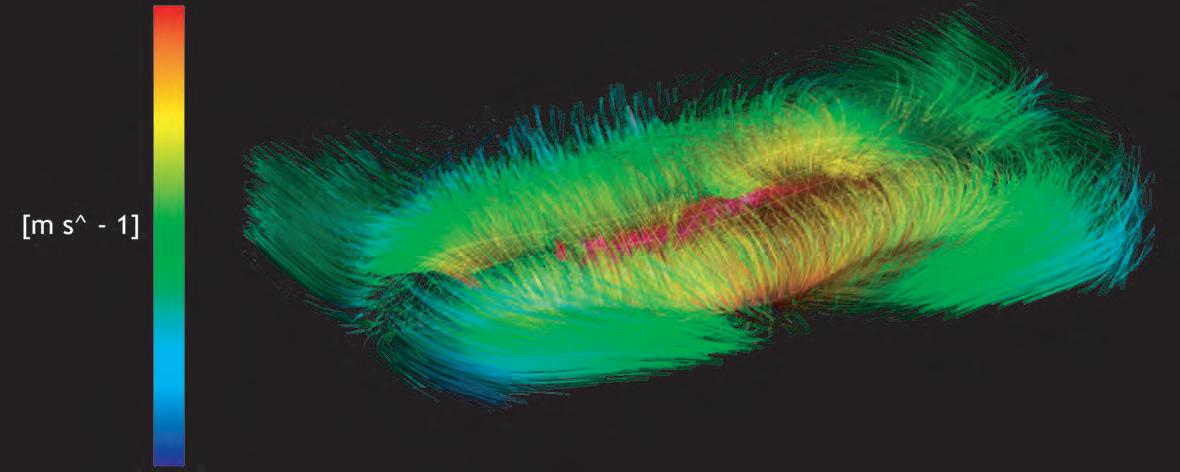
“a parallel can be established between air density and wind velocity, where a decrease on density is translated on an increase of velocity”
Velocity - Gradient 2.567e+001 1.517e-001 [m s^ - 1] Density - Gradient 2.567e+001 1.517e-001 [kg m^ - 4] Pressure - Gradient 5.946e+001 9.743e-002 [kg m^ - 2s^ - 2]
Mapping of gradients on building envelope Environment Cast in Building Wind flow simulations
070

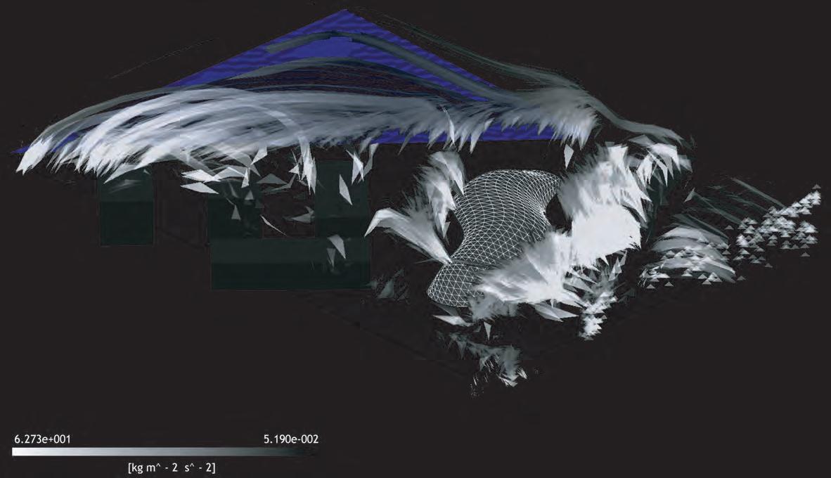
Building
Wind flow affected by building and surrounding environment, wind velocity and density gradient on air volume
In order to have a more realistic scenario, the building is placed into the context of the site, where other constructions will have an influence in the wind flows around the envelope.
On the image of the top (where wind velocity is shown), the influx zone is at the right hand side, the green color symbolizes the original wind speed, set at 10m/s according from the site meteorological records for spring time. The red zones of the image are describing and increase of the wind velocity. Because of the shape of the envelope designed, the wind flow is accelerated trough the surface achieving the highest speed at the top of the surface -red zones- therefore defining low pressure zones. Because of the smooth “wing like” shape of the envelope the increase and posterior decrease of the speed is gradual, going from greens to reds and back to greens colors. This is considered as an achievement since the parameters planned for the building shape were set aiming to manipulate the wind flow in a controlled manner. The wind flow is only increased, never reduced. This fact makes more efficient the ventilation of the building. In opposition to this in the square volumes of the surrounding buildings the blue colors are showing turbulent zone where the speed of the original wind flow decreases.
The image on the bottom shows the density gradient of the air volume around the building and surrounding site. Since the increase of density can be translated into decrease of speed, this graph corroborates the ability of the building to control and accelerate wind flow, since no increase of density is shown directly over the building. On opposition to this, they are directly above the square volumes around.
“the wind flow is accelerated trough the surface achieving the highest speed at the top of the surface -red zones- therefore defining low pressure zones. Because of the smooth “wing like” shape of the envelope the increase and posterior decrease of the speed is gradual”
“The wind flow is only increased, never reduced”
Environment Cast in
Wind flow simulations
Wind velocity Density gradient on air volume 071
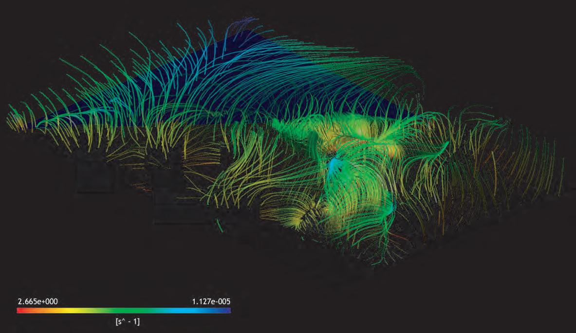
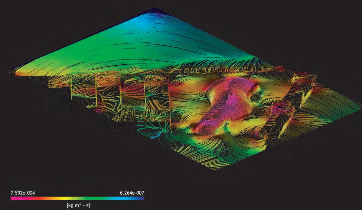
Wind flow affected by building and surrounding environment, velocity gradient and density gradient on surface level
The lines on the top image are describing the velocity gradient from the surface level towards the air volume and then back to the surface level in other areas of the building or the surrounding environment with equal velocity gradient. Therefore, the high amount of lines over the envelope is understood as the numerous connections between different degrees of wind acceleration over the building. Despite the fact that there is a big –pressure- gap between the lowest and highest pressures zones on the building surface, there are several zones that haves the same velocity value, this due to the progressive acceleration and posterior speed reduction of the wind flow.
The image at the bottom is showing the relations between densities of air on differences areas at surface level. The colors going from the yellow/oranges towards pinks/violates are describing the reduction of air density.
On the forthcoming two images, different outputs already addressed in an isolate manner are overlaid with the aim of understand the interrelation between different graphic interpretations to the same conditions. In relation to this, is important to state that all this images/graphs are the product of one setting of environmental conditions, so all of them are different versions to the same phenomenon that is occurring under certain predefined circumstances. Furthermore the interrelation of the isolated information extracted from them will later -in addition with other factorsdefine population and kinetic logics within the system.
“is important to state that all this images/graphs are the product of one setting of environmental conditions, so all of them are different versions to the same phenomenon that is occurring under certain predefined circumstances”
Density gradient on surface level Velocity gradient Environment Cast in Building Wind flow simulations
072
Environment Cast in Building
Wind flow simulations
Wind flow affected by building and surroundings environment. Readings superposition of wind velocity and velocity gradient

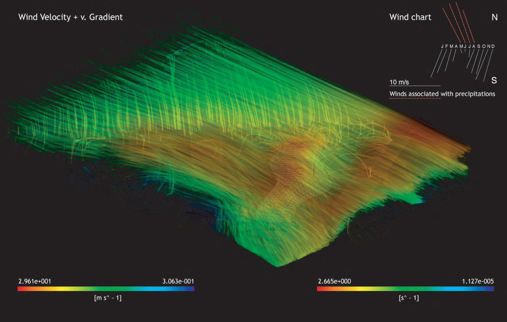


10 m/s
Winds associates with rain
 Wind velocity + Velocity gradient
[m s^-1] 2.962e+001 3.063e-001 [s^-1] 2.665e+000 1.127e-005 073
Environment Cast in Building
Wind flow simulations
Wind flow affected by building and surrounding environment. Readings superposition of den density gradient and pressure gradient
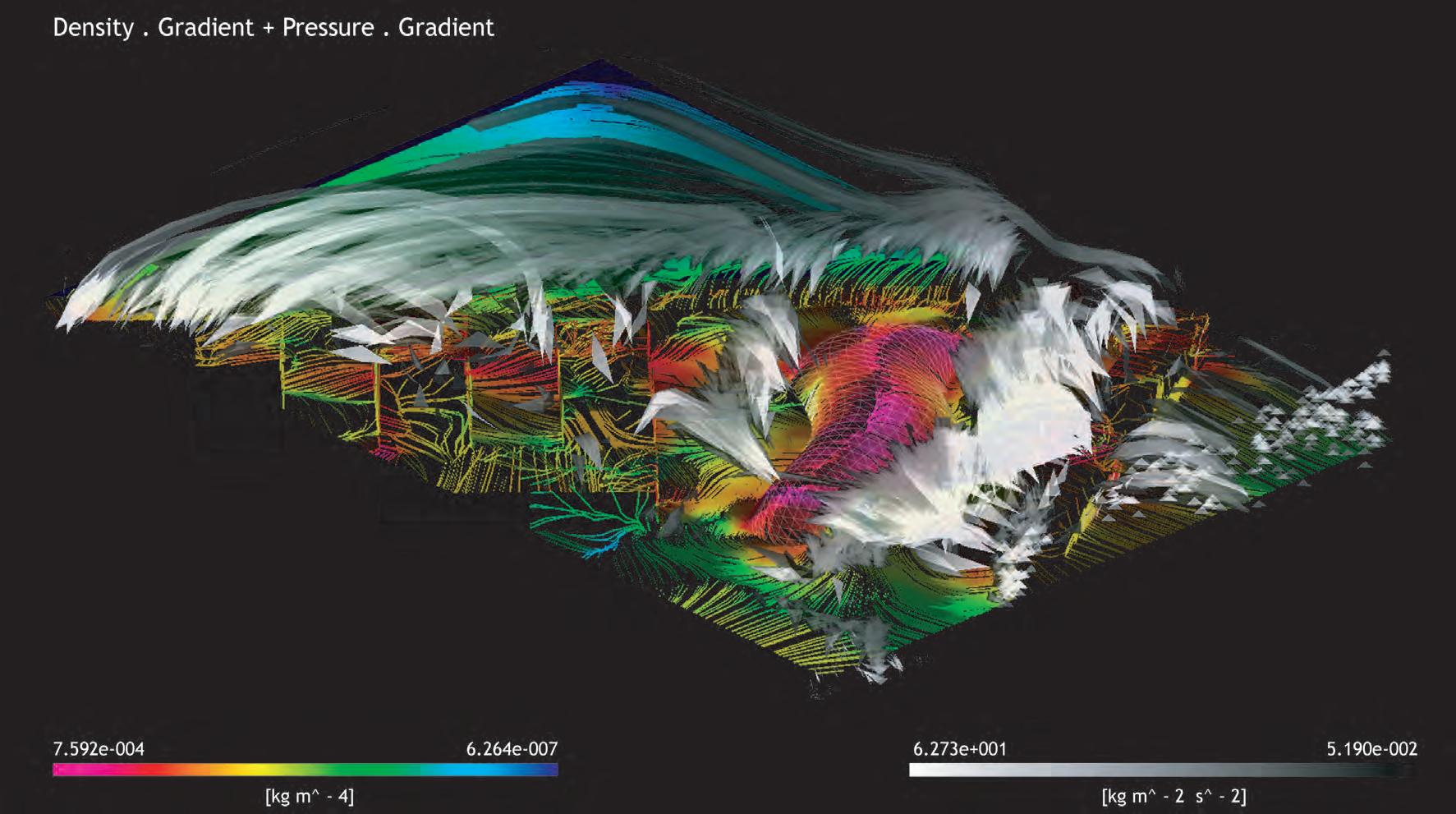


gradient + Pressure gradient [kg m^-4]
m^-2 s^-2]
074
Density
7.592e-004 6.264e-007 [kg
6.273e+001 5.190e-002

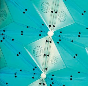
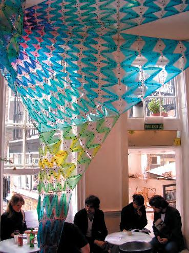
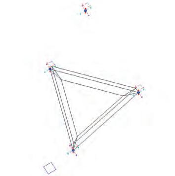
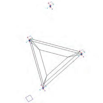
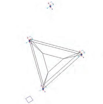
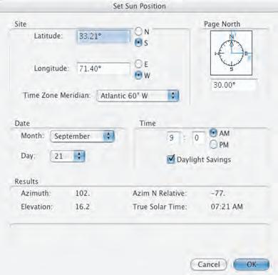
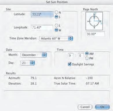
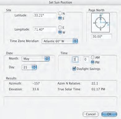
Light regulator system concept
One important issue in relation to the climatic control performed by the envelope is the regulation of light quality and exposure. In the case of the devices to control the light in the system, they are not dynamic, so they don’t change together with the seasons of the year as threes do, nevertheless thanks to the highly tessellated envelope the light can be modulated in a very specific manner in accordance to a predefined set up. A previous experience in this topic is already been made in the context of the EmTech program, during the AA exhibition 2005 the EmTech group developed a parametric day light filter. On that experience the aim was to modulate the light in relation to the degree of exposure of the different areas affected by day light and also the gradual definition of colors showing the stresses taken by the -form founded- cable system supporting the translucid components. Despite the fact that the scale of the project in this case is much bigger, the concepts related with the light modulation are similar. However in this case the devices -components- to control light exposure and permeability are much sophisticated. Acting as a large collection of small diaphragms, where each cell can be individually set in its degree of opening allowing 25, 50 or a 75% level of transparency in relation to the total area of the component.
The control of light exposure will not only define the quality of the light in the interior of the envelope. Also this sub-system has a major role in the control of temperature inside the building, since the movements of the air volume is affected by changes of temperatures at the envelope surface induced by light exposure.
In order to inform the process of how the light permeability should be defined along the surface, several readings of how the sunlight is projected over the building surface are taken. The parameters for the three most representative dates of the year are set for the specific location of Valparaiso, Chile. Equinox -September 21-, Summer Solstice -December 21-, Winter Solstice -May 21- (dates for southern hemisphere). Four readings will be taken in each of these three days: 9AM, 12PM, 3PM, 6PM. A strategic combination of these isolated images will define a particular light pattern informing then how to populate the surface in relation to the light control.
Light mapping Component variations Set_ 1 75% of transparency Set_ 2 50% of transparency Set_ 3 25% of transparency
Environment Cast in Building
Date and locations coordinates Equinox Date and locations coordinates Summer Solstice Date and locations coordinates Winter Solstice C_2.6.2
Nature model of light control filter in relation with seasons
075
Parametric day light filter system, detail and global organization.
9:00 AM
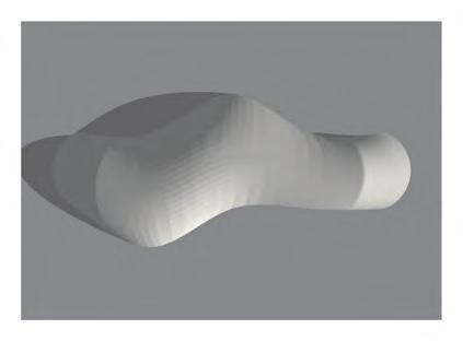
12:00 PM
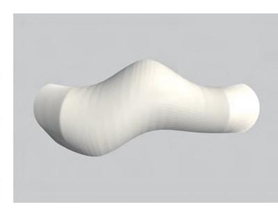
3:00 PM
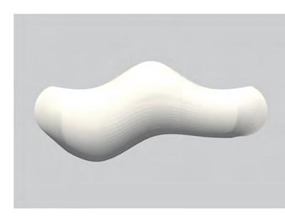
6:00 PM
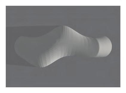
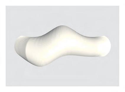
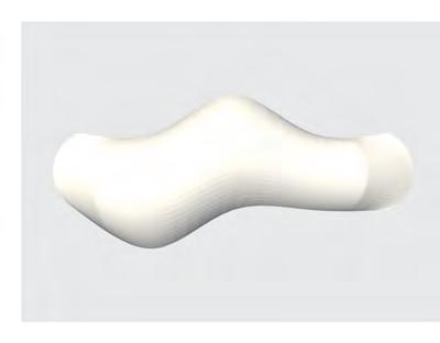
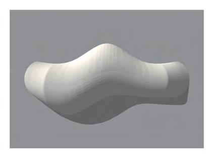
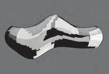

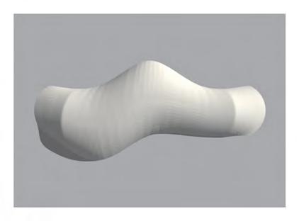
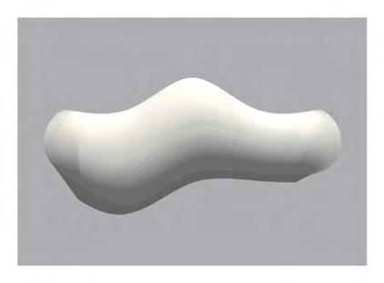
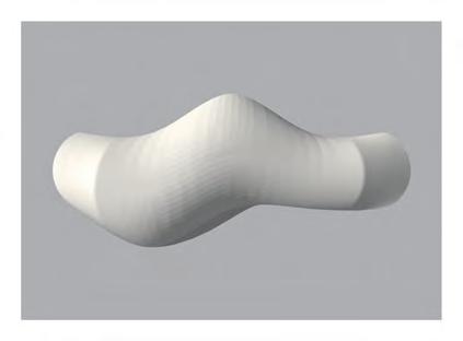
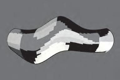
Different light reading over the year.
The light mapping process aims to identify the different zones and times of the day when the sunlight rays hits the surface in a direct manner, recognizing when the position of the sun is “more” perpendicular to the surface, these zones “more” perpendicular to the sun rays are identified by the brightest areas at the surface level at different times of the three sample days during the year. Once that these zones are secluded they are combined together creating a specific pattern to each of the three days. This pattern shows the superposition of the zones as the four mappings are layered. When two or more zones (a maximum of four) are over layered the intersection area gets whiter, therefore that specific zone is more likely to have an overall direct exposure to sunlight rays. Due to the geometrical characteristics of the triangular components, the zones where the light is hitting directly are more likely to allow light penetration. Also these zones are identified as warmer zones on the surface, influencing the movement of air inside the building.
The three seasonal different patterns can be understood by the influence of the sun transit and its light angle in relation with the season of the year. The overall most exposed zone, is the one facing the north. It also clear how during the summer the lighter area on the back of the building is moving downwards trough the north face as the angle of the sun decreases during the equinoxes, to finally reach the lowest strip of the north face at the winter solstice.


“aims to identify the different zones and times of the day when the sunlight rays hits the surface in a direct manner, recognizing when the position of the sun is “more” perpendicular to the surface”
“the zones where the light is hitting in this manner, are more likely to allow light penetration”
Environment Cast in Building Light mapping
Daily light patterns superposition
Equinox Summer Solstice Winter Solstice
North South East West 076
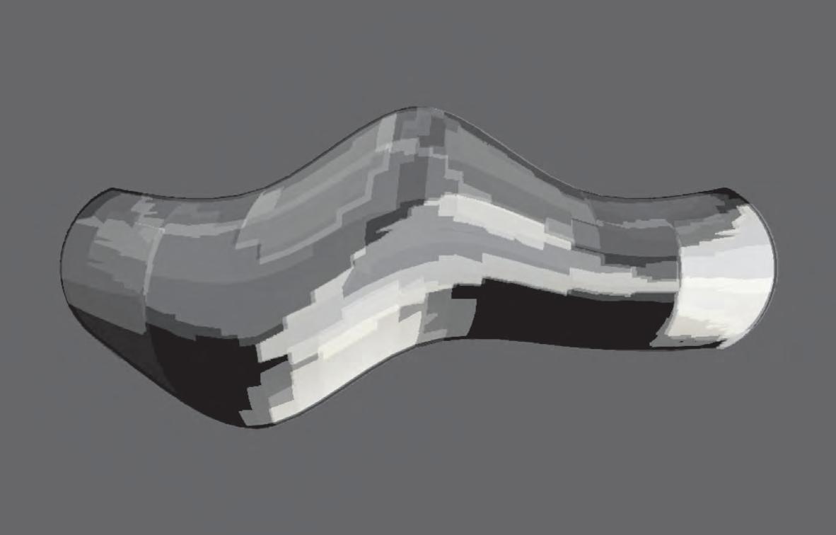
Overall high light exposure
Overall medium light exposure
Overall low light exposure
Light mapping diagram
Equinox
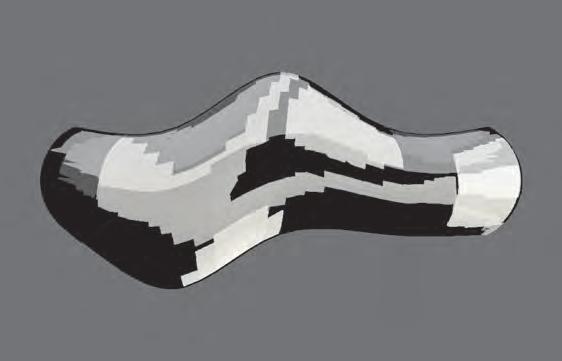
Summer solstice
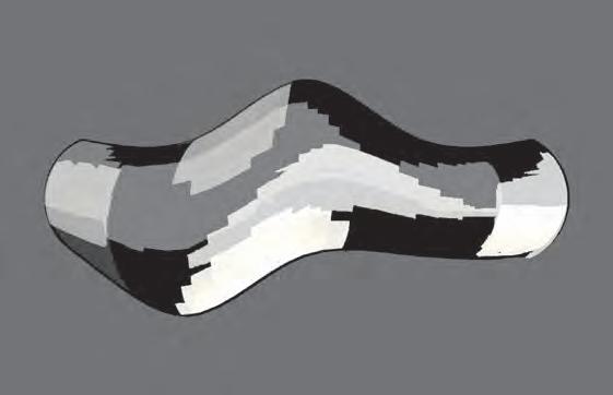
The same processes described before is repeated, this time using the pattern extracted for each of the days. The aim is to define an overall pattern of light incidence the whole year. Again the lighter zones are representing the areas of the surface more likely to receive direct influence of the sun light. Thus they are identified as the most permeable -to the light- zones of the building. This will have an influence in the pattern inside the building, due to the calculations between these parts of the surface and the light angle; this will later define the light choreography at floor level. On the other hand the whiter the surface area the warmer its tendency, on opposition to this, where no direct sunlight influence is registered the colder the surface zone is.
At this point is important to state that the light mapping combination procedure is not an exceptionally accurate representation of what happens in the reality. A minor problem is identified in the final superposition of the mappings, where the north face of the building it is not the overall brighter one. Since in the south hemisphere the sun always transits trough the north this is considered as mismatch. In deed the brighter zones are the ones facing the sunrise (East), what it is not completely inaccurate, considering that the north zone is much brighter than the zone facing directly to the south, what is a correct relation. Looking backwards, the initial light readings are correct, nonetheless the combination of them it is not the most faithful one.
At the time that this remarks where made, the information gained from this process have had already determinate the forthcoming chapter of the thesis. Therefore the mappings remains as a valid way of understanding the design process, therefore the investigation can move forth ward with out jeopardizing the successful deliver of the tasks and aims intended to achieve with the light control system and also without affecting the major framework of the thesis.
Winter solstice
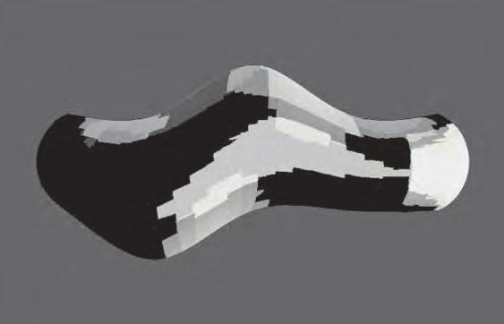
Environment Cast in Building Light mapping
Seasonal light patterns superposition
North
East West 077
South

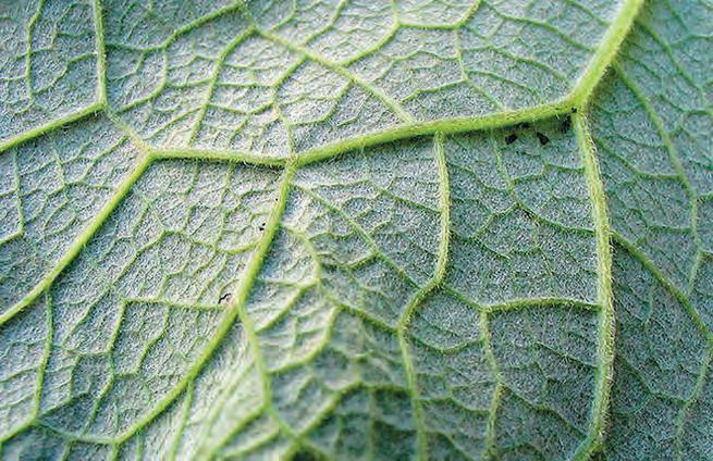
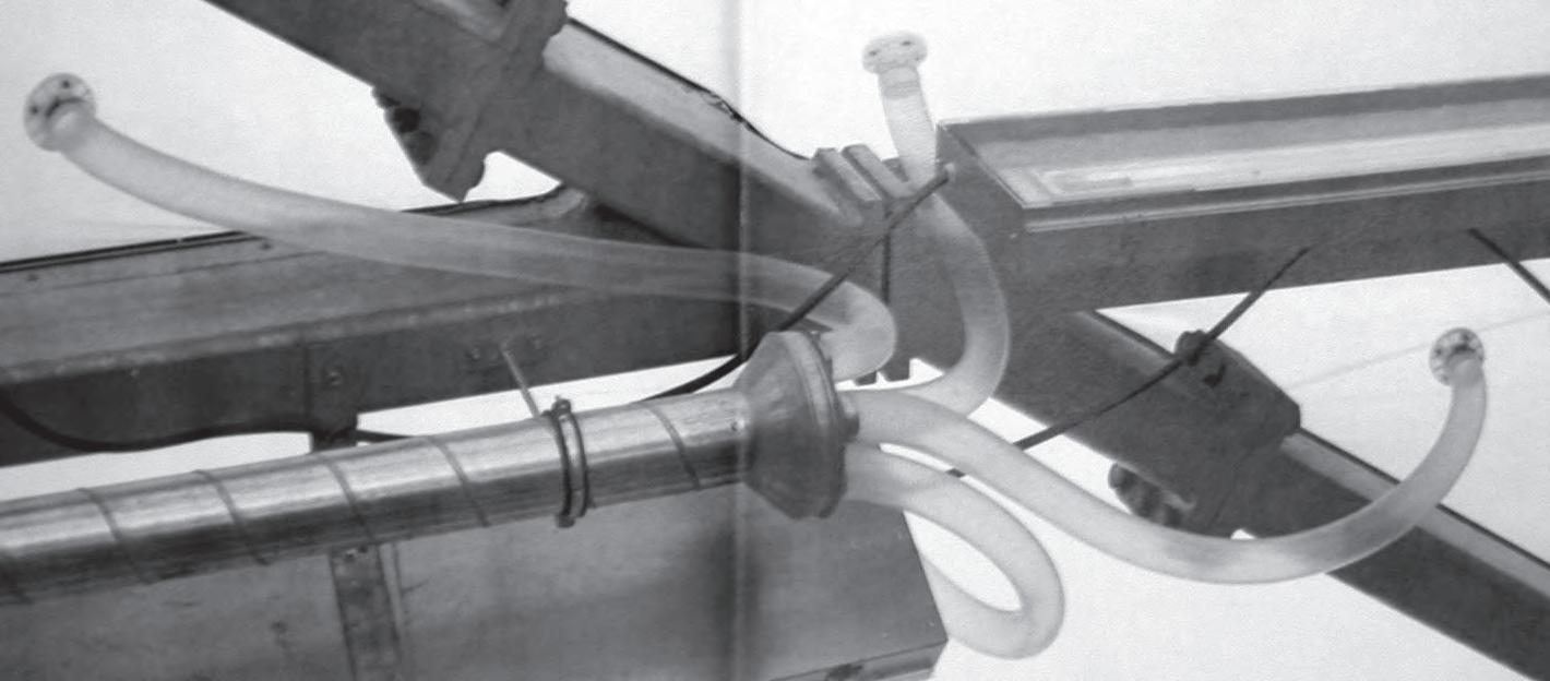
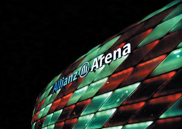
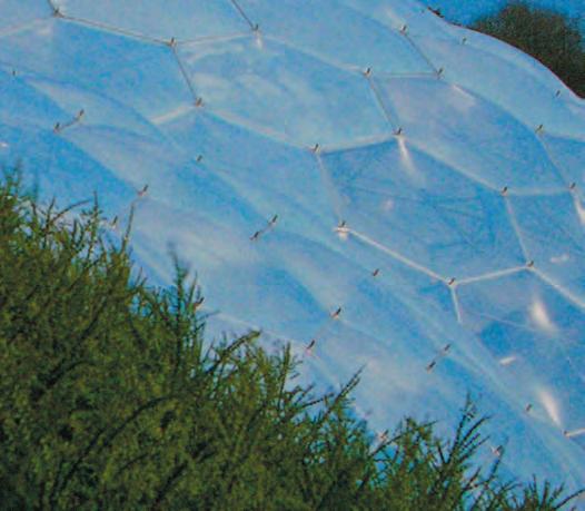
Concept
Again using nature as a source of research and observation is proposed a water collection/irrigation system in order to stimulate the muscles or pneumatic devices along the climatic envelope. Due to the complexity of the task, this system is addressed from the conceptual point of view, assuming that to define it properly can be considered itself as a thesis. Nevertheless the principles and implications that such a system requires are clearly stated in this chapter. For this task isolated concepts, physic principles and techniques are combined together in a simpler way aiming to rationalize and allow the implementation of the dynamic devices needed to have an active structure.
Basically the concept principles are: Firstly divide the envelope into porous patches -conformed by active cells-, and collection patches -conformed by receptive cells-. The water collected in the receptive cells is transported using the capillary physic concept, where due to surface tension; water can be transported upwards (depending on the diameter of pipes used).
As is been done before in the examples addressed (Allianze Arena, Eden Project), a higher hierarchical system defines how the water is distributed. Therefore the individual feeding of each cell is controlled in relation to settings previously defined. The parameters to define which cell is activated and when, are extracted from the strategies of climatic control in accordance to the relation between the building and the environment where is placed. But basically with dry weather the system is fully open, due to the characteristics of Mediterranean climate this occur during summer time when temperatures raises, thus the envelope is permeable and therefore ventilated by the action of the predominant winds. During winter the rain water is collected and taken into the muscles, stimulating their contraction. Thus the envelope close itself until the dry weather came back and the raises in temperature evaporates the water contained in the system. The muscles switch to the relaxed configuration and the envelope is permeable again. Furthermore another intermediate state between fully open and sealed are proposed and explained with more detail in the next chapter of the thesis.
“with dry weather the system is fully open, due to the characteristics of Mediterranean climate this occur during summer time when temperatures raises, thus the envelope is permeable and therefore ventilated by the action of the predominant winds. During winter the rain water is collected and taken into the muscles, stimulating their contraction”
Environment Cast in Building Watering system C_2.6.3
Water collection model in nature (self cleaning leaf)
Water irrigation model in nature (capillaries in leaf)
Pneumatic control pressure system for individual cells
Organizations with high population of pneumatic cells controlled by global system, Allianze Arena, Eden Project.
078
Conceptual drawing
Storage points and irrigation veins
Top
Conceptual drawing
Collection zones defined by building shape
Top view Principles
Storage points Capillaries
system
Conceptual drawing
Collection zones defined by building shape
Front view
Conceptual drawing
The diagrams on this page are showing the conceptual implementation of the watering system, where the rain water is collected by gravity and conduced by the slope of the surface towards storage points strategically located nearby the porosities intended to stimulate. From the storage point the water is “self” conduced by the principles of capillary action and surface tension into the muscles. This is achieved using several narrow tubes, in the case that the dynamic cells are located in higher point of the surface. In order to have an efficient stimulation, the capillaries are taken into the muscles trough the inside of the cable that is attaching the muscles with the cell frames.
Capillary action definition:
Capillary action or capillarity (also known as capillary motion) is the ability of a narrow tube to draw a liquid upwards against the force of gravity. It occurs when the adhesive intermolecular forces between the liquid and a solid are stronger than the cohesive intermolecular forces within the liquid. The effect causes a concave meniscus to form where the liquid is in contact with a vertical surface. The same effect is what causes porous materials to soak up liquids.
A common apparatus used to demonstrate capillary action is the capillary tube. When the lower end of a vertical glass tube is placed in a liquid such as water, a concave meniscus forms. Surface tension pulls the liquid column up until there is a sufficient weight of liquid for gravitational forces to overcome the intermolecular forces. The weight of the liquid column is proportional to the square of the tube’s diameter, but the contact area between the liquid and the tube is proportional only to the diameter of the tube, so a narrow tube will draw a liquid column higher than a wide tube.
Surface Tension short definition:
In physics, surface tension is an effect within the surface layer of a liquid that causes the layer to behave as an elastic sheet. It is the effect that causes capillary action.
Definitions extracted from //www. wikipedia.org
Conceptual drawing
Collection zones defined by building shape
Side view

Environment Cast in Building Watering
079
Environment Cast in Building Watering system
Specifics
The irrigation logic is based on a regional scale, where a single storage point is feeding a district of active cells. The volume of water that each of this collecting points can storage is defined by the amount of muscles that is feeding, so when all the muscles are fully contracted the storage point is empty. Preventing the pneumatic cells to remain close when the weather has switched to dry, when this happens the exact water contained in the regional system evaporates and the organization switch to the permeable configuration. Thus the volume of water that the collecting point can storage must be calculated in relation with the amount of muscles connected to it. The volume of water collected can be easily controlled by the depth of the base inside the collecting cell and in relation with the angle of the cell depending on its position through the surface.
Therefore in the system there are several communities of passive and active cells interconnected by capillaries tubes, these independent organizations are reacting in a passive/reversible manner to the water levels of the environment. Eventually depending on the season of the year some of this organization can be shutdown, by having the collecting point permanently drained, so the water is evacuated before it is distributed trough the system reaching the interconnected cells. This strategy can be implemented during mid season (fall, spring) when despite the rain; there are zones that should remain open to permit the particular ventilation setting for that time of the year. Furthermore some water communities can have a storage point with more capacity that the exact required to feed the cells, then this regional sub-organization remain sealed for a longer period of time after the switching of environmental conditions. These strategic topics are revised, explained further and partially defined in next chapter of the thesis.
“The volume of water that each of this collecting points can storage is defined by the amount of muscles that is feeding, so when all the muscles are fully contracted the storage point is empty. Preventing the pneumatic cells to remain close when the weather has switched to dry...”
Section view of permeable configuration (ventilated during hot/dry season)
irrigation detail Water storage cell detail
Section view of sealed configuration (closed during cold/wet season)
Muscles
Porosity open (relaxed configuration)
Porosity
(muscle
Storage cell charged (rain season)
Storage cell empty (dry season)
closed
stimulated)
Muscles Capillaries driven trough the cell frames first and then through the cable attached to the muscle.
Elastic device to bring back porosity to open configuration
Water storage point permanently connected to muscles by capillaries
Pipe filled with several capillary tubes
Base depth interrelation to water needed to feed community of active cells
080
The angle of the cell affects the depth of the base in order to storage more or less water
Chapter three
Genotype makeup, observed Phenotype
081
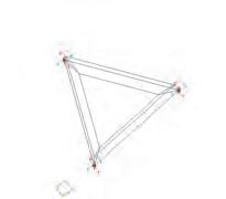




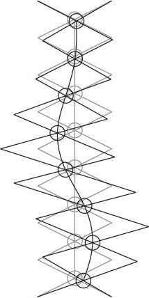
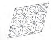
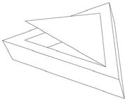


Shape and tessellation
This chapter is focused on the strategic combination of isolated inductive approaches to the issues related with the envelope design. At this stage of the investigation, the information gained from each of the isolated design and observation procedures is negotiated in an instrumental way aiming to define a Genotype for the building.
Genotype:
The genotype is the specific genetic makeup (the specific genome) of an individual. Together with the environmental variation that influences the individual, it codes for the phenotype of that individual. definition extracted from //www.wikipedia.org
The chart on this page resumes the concepts behind the specific procedures described in the previous chapter, where shape and tessellation are defined according to the following criteria:
Path number one starts from tessellation logics observed in nature, more specifically in diatoms, from there is defined firstly a component or “tessella” (step 2) and later the proliferation logics for that component (step 3), finally this path will select the more suitable tessellation layout for a global shape extracted from the combinations of paths number two and number three (step 5).
Path number two starts from pneumatic behaviours observed in nature, more specifically in the dynamic strategies of plants based in the implementation of Turgor pressure principles. From there is designed a pneumatic device or muscle (step 2), later on comes the definition of a pneumatic cell (step 3). The aim for this cells is to ventilate in a passive manner the system where is located, therefore the final stage of this path is the election of the most suitable global shape to be passively ventilated by a high population of pneumatic cells nested over the surface (step 4). This surface is one of the nine outputs from path number three.
Path number three is referred to environmental issues, and they will have an incidence in the genotype (as is described in the genotype definition). The specific location and the environmental conditions are defining a global shape parametric engine (step 2), from there nine outputs are extracted (step 3), and each of them is exposed to horizontal environmental influence. At this point, one out of the nines shapes is selected by path number two (step 4). This shape is described in 11 different -tessellation- ways.
Path number one picks the most appropriate configuration (step 5) according to differentiation and number of overall components (around 1000). The combinations between the selections of steps 4 and 5 give us the final shape with the tessellation arrangement for that specific surface (final step).
Building Genotype Definition procedure
Step_1 Step_2 Step_3 Step_4 Step_5 Final Step Path _1 Path 2 Path 3
C_3.1.1 082
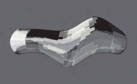
Overall high light exposure zone
Overall medium light exposure zone
Overall low light exposure zone
Overall hight light permeability
of translucency
Building Genotype Definition procedure
Overall medium light permeability
of translucency
The light permeability strategy defined for the building will set the population logic, defining the degree of transparency of each of the components to be nested in the already defined tessellation layout. Where each of the four sided planes are deduced with triangular components.
Taking the overall light mapping defined in the previous chapter, the intention with this light configuration is to have an overall constant light pattern inside the building, controlling the permeability in relation to the direct light exposure of the different areas of the envelope. This decision is taken firstly due to programmatic reasons and secondly because it is a straightforward way in order to prove and explain this feature of the system. Therefore the zones of the surface with an overall higher exposure to light trough the year are populated with components where the diaphragms are closed to the smallest configuration (25% light permeability), and so on where the exposure is average the degree of translucency is 50%. Finally in the zones whit overall low light exposures the diaphragms are fully open to the maximum 75% of translucency.
Independently if this light configuration is the most interesting or instrumental in order to gain the most of the highly differentiated system the procedure applied can be reversed. Therefore zones with high light exposure can be opened to the maximum permeability; on opposition to this the zones with low light exposure can be set to the minimum of translucency and so on. At the end the system allows to play with these factors according to the intention of the designer/architect.
Is important to quote also the role that is playing the tessellation lay out, where areas of the surface with more geometric information (curvature) are highly tessellated, this allows major light control since there are a larger amount of components to play with.
The images on the left are showing the specific zonification of the three kinds of components trough the surface, in relation with their translucency level. The last image at the bottom is showing the final configuration of the building with the three zones combined.
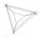
Overall low light permeability
of translucency
Final grid shell configuration
“.....the intention with this light configuration is to have an overall constant light pattern inside the building. This decision is taken firstly due to programmatic reasons and secondly because it is a straightforward way in order to prove and explain this feature of the system”
be
Population procedure defined by light exposure trough the year Shade / light patterns and grid to
populated
75%
50%
25%
C_3.1.2
Light permeability
083

Z_1 High pressure zone (south wind) Influx/suction
In relation to wind direction.
Building Genotype
Definition procedure
Identification of pressure zones
Porosities distribuition
Z_2 Inter media pressure zone (south wind) suction/Influx
In relation to wind direction.
Z_3 Low pressure zone _ suction
Having already defined the transparency level for each of the cells, now the process focused on defining which cells or components have pneumatic/ dynamic properties. In order to inform this process the readings from the wind flow simulations are addressed, where three major zones are identified in relation to the predominant wind condition at the site (speed and direction).
There are two different Influx/Suction zones at both sides of the building (south and north) this two sections are switching from high pressure to intermediate pressure, in relation with the wind direction. In central Chile the wind always blows from the South, South/West direction. Whenever bad weather (rain) the wind is switches to North, North/West. In accordance to the CFD tests, the lower section of the windward face of the building has the higher pressure level of the envelope, while the opposite face has an intermediate pressure level. On the other hand the third pressure zone (low) is at the highest part of the envelope. Whenever the wind is blowing (south or north), a lower pressure zone is created at the top of the building. This is due to the -wing like- shape of the building.
Therefore these three zones are selected as the sections of the building with porous active cells. The combinations of when the zones are opened or close, or more specifically, how many of the cells are open or close is set by the ventilation strategy defined for the building for particular time of the year.
In relation to this, the overall strategy is:
During summer time when the weather is hot and dry, the three zones (Z_1,Z_2,Z_3) are fully open, allowing a high level of ventilation where isotherms conditions between inside and outside are expected, preventing the formation of a “greenhouse” effect.
During winter, when the weather if relatively cold and wet, the overall configuration is sealed, nevertheless in order to have air renovation and prevent condensation, some cells (this cells are open through the whole year) are open in the highest section of low pressure zone (Z_3). On parallel some cells equally distributed through zone number one (Z_1) are open aswell (during winter this zone is expected to be the zone of intermediate pressure zone, due to switching of the wind to the north). So this configuration aims to have a very slow air renovation.
During mid season (spring, fall) the strategy is to have an intermediate state of ventilation, this is achieved by opening a fraction of the porosities in the high and low pressure zone (Z_1,Z_3). An estimated 50% of the cells for each of these zones should be opened, achieving then a slow but constant renovation of air, without loosing too much heat during the process.
Combined pressure zones
“....the lower section of the windward face of the building has the higher pressure level of the envelope, while the opposite face has an intermediate pressure level. Whenever the wind is blowing (south or north), a lower pressure zone is created at the top of the building. This is due to the -wing like- shape of the building”
Pressure map according to wind direction
C_3.1.2
Air permeability
084
Output from previous procedure
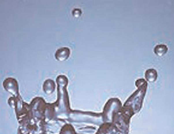
Implementation of water activated pneumatic devices in the building
suction/influx porosities feeding zone
Suction porosities feeding zone
Comvined zones of water collection/feeding
Watering
Identification of water collection zone and distribution to permeable areas
In order to feed with water the porous zones of the system, the rest of the envelope is populated with sealed cells. The function assigned to these areas of the surface is to collect and storage the water used to stimulate the muscles of the porous cells. The storage and feeding techniques have already been described in the previous chapter. Here are addressed the specific interconnected sub feeding/porous zones.
In general there are three major collection zones, one for each pressure zone. The feeding zone is conformed by the collection of sealed cells surrounding the active cells. On each of these three isolated systems there are sub-independent organizations. Each of this communities is organized by an area of collection where the water is taken by gravity towards a storage point conformed for one or more cells. From there, the water is conduced by capillaries into the muscles. As is been said before, the amount of water that can be storage is previously defined in accordance with the sealed/ permeable cycle of the community.
The suggested sub organizations of communities is informed by the overlapping of two environmental cast over the building surface, on the one hand the light mapping and on the other hand the pressure zones identified by CFD. These two processes are tied together due to the influence of the sunlight in the temperatures over the envelope. So this will have an incidence in the movement of the air volume inside the envelope.
Each of these systems has three different sub-zones in the case of the light system defined by three levels of translucency, and in the case of the pressure system three different pressure zones. The product of the overlapping of the two systems and the negotiation between their characteristic, is 15 sub hybrid zones (see next page). The logic used to label these zones is based on the principle that the sunlight exposure will rise the temperature on some areas of the building surface, thus the air inside the building will have the tendency to move towards that specific area. Therefore when, for instance, an area of high light exposure is intersected by an area of low pressure, the combination of both physic principles will provide -in this case- an extra suction power, and then this sub-zone can be considered a “turbo” suction area. On opposition to this a high pressure zone can increase it influx properties due to the intersection with a low light exposure (cold) zone and so on, in another cases the relation between suction and influx can be partially annulled by this reason.
Therefore the water collection/feeding system will be subdivided in fifteen colonies of interconnected cells. At this point the research only reaches the definition levels to determinate which are the active/pneumatic cells for each of the sub-systems. The specific collection zones are defined, so far, only at the hierarchic level of the bigger pressure zones. The sub-hierarchical level of feeding zones will be a subdivision of the higher level feeding system zone by the number of sub-zones contained on it.
For instance the low pressure zone is divided into six sub-suction zones; therefore the overall feeding area for the low pressure zone is subdivided in six sub-feeding zones. (See next page)
Influx/suction porosities feeding zone
Building Genotype Definition procedure
C_3.1.3
085
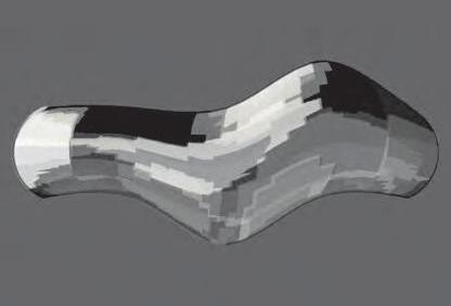
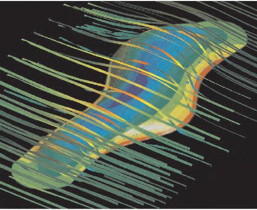
Pressure map according to wind direction.
Building Genotype, Definition procedure
Light and Pressure systems negotiation
Negotiation between sun exposure and pressure zones
Speculation about the temperatures on the surface and their effect in the movement of air inside the building
Population logic in relation to sun light exposure
Pressure/water collecting zones identification on building surface
Intermediate pressure

Sub_A_Z_
Intermediate pressure
Mild zones
Sub_A_Z_3
Convined Light and pressure systems
Overall water feeding/collection zones
Differentiation in permeable “Sub Active Zones” by effect of changes of temperatures in the surface of the building due to sunlight exposure.
Sub_A_Z_4
Intermediate pressure
Warm zones
Sub_A_Z_5
Sub_A_Z_6
Low pressure
Sub_A_Z_7
Low pressure

Low pressure
Cold zones
Sub_A_Z_11
Hight pressure
Mild zone
Sub_A_Z_13
Sub_A_Z_
Sub_A_Z_12
Sub_A_Z_15
Shade / light patterns on surface
C_3.1.4
086

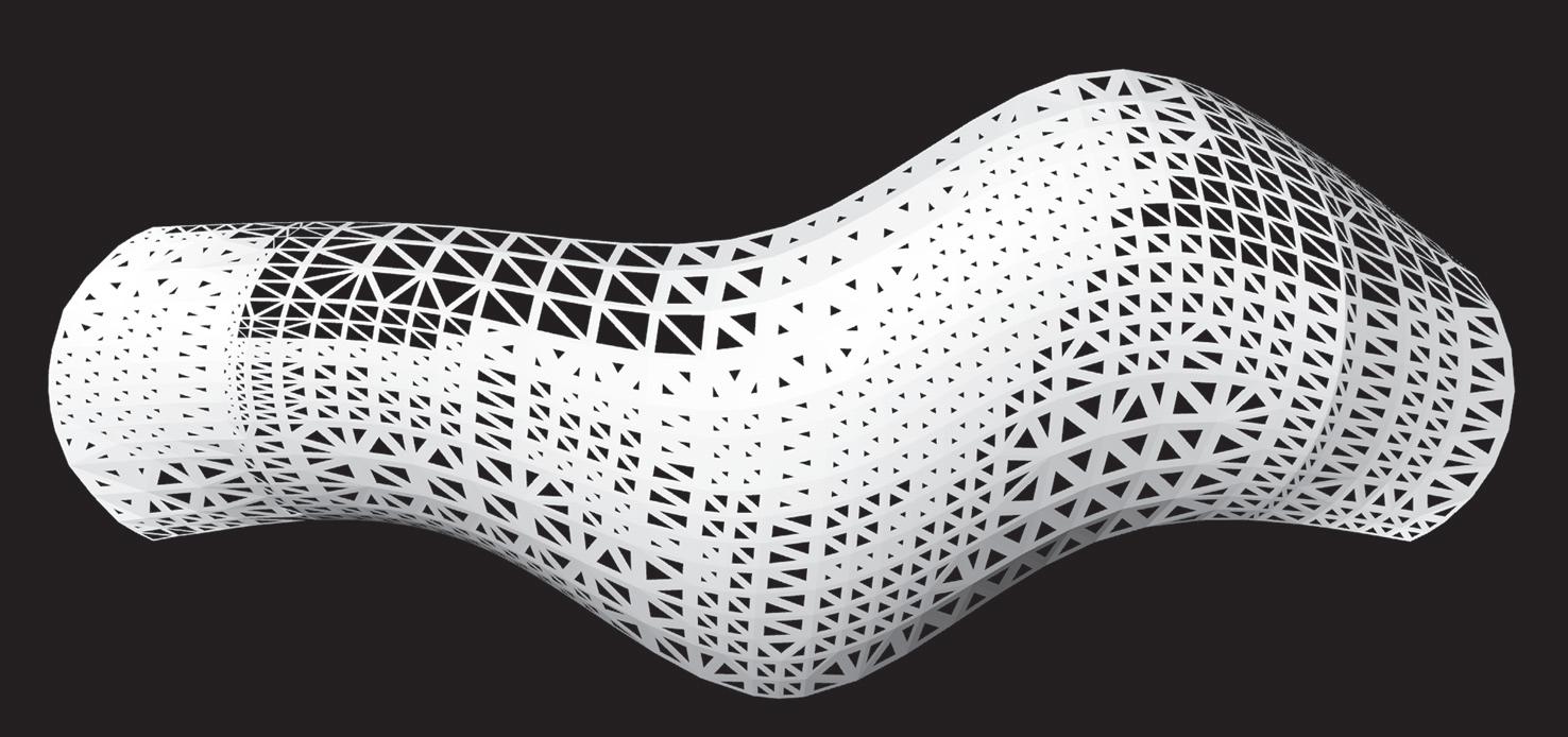
Phenotype Digital model North Elevation Plan View C_3.2.1 087
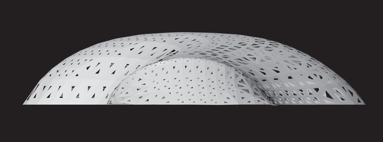

088
West Elevation East Elevation Phenotype Digital model
Phenotype
Digital model
Soth Elevation
Perspective View_1

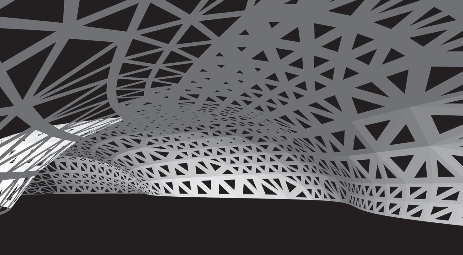
089
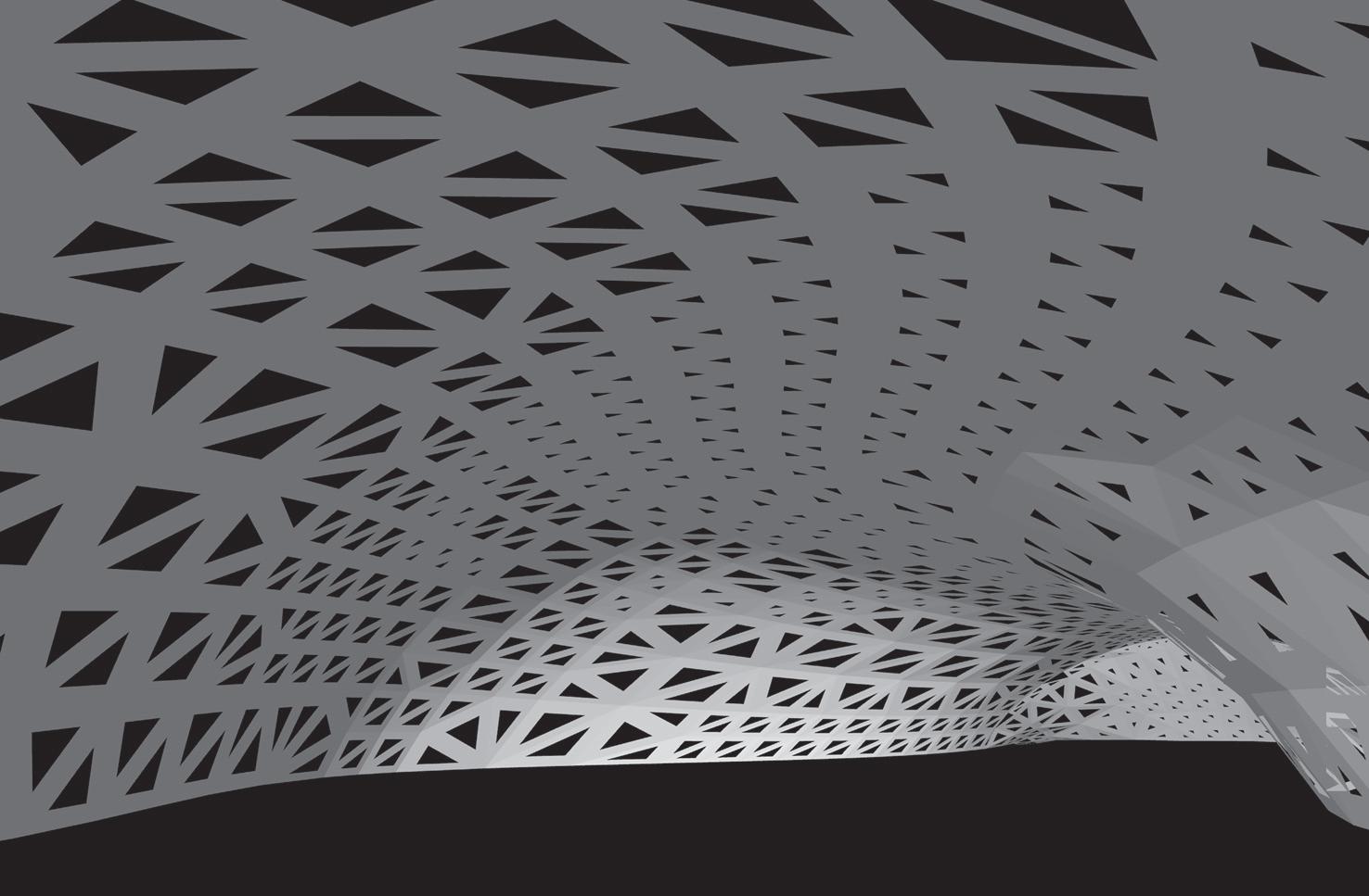
Perspective View_2
090
Phenotype Digital model

An analog model of the sample building is made with the intention to prove the parametric design principles imbedded on the system and their relation with the CAD/CAM technologies. On the other hand the maquet if used to observe light permeability hence sun light patterns inside the building.
The scale for the model is 1:100, thus the maquet has and overall length of 100cm. The populations logics defined by the genotype of the building, where applied in the digital construction on Generatives Components. The Sub-zones defined by the combination of the light and pressure systems where used as subdivision in the quartering of the envelope. On addition to this the pressure zones where labeled using three different colors: Light grey for the high pressure zone, grey for the intermediate pressure zone and black for the light pressure zone.
“The Sub-zones defined by the combination of the light and pressure systems where used as subdivision in the quartering of the envelope”
C_3.2.2 Low_3_A Low_3_B Low_3_C High A High B High C High D High Low_2_A Low_2_B Low_2_C 1 A 1 B 3 A 3 C 3 D 3 E 3 F Med_3_A Med_3_B Med_2_A Med_2_B Med_1_A Med_1_B Low_1_A Low_1_B 2 A 2 B 2 C 2 D 2 F 2 G 2 H
Cad_Cam construction process 3d partition of global shape Phenotype Analog model
091
Building 3D digital model and quartering in 36 pieces
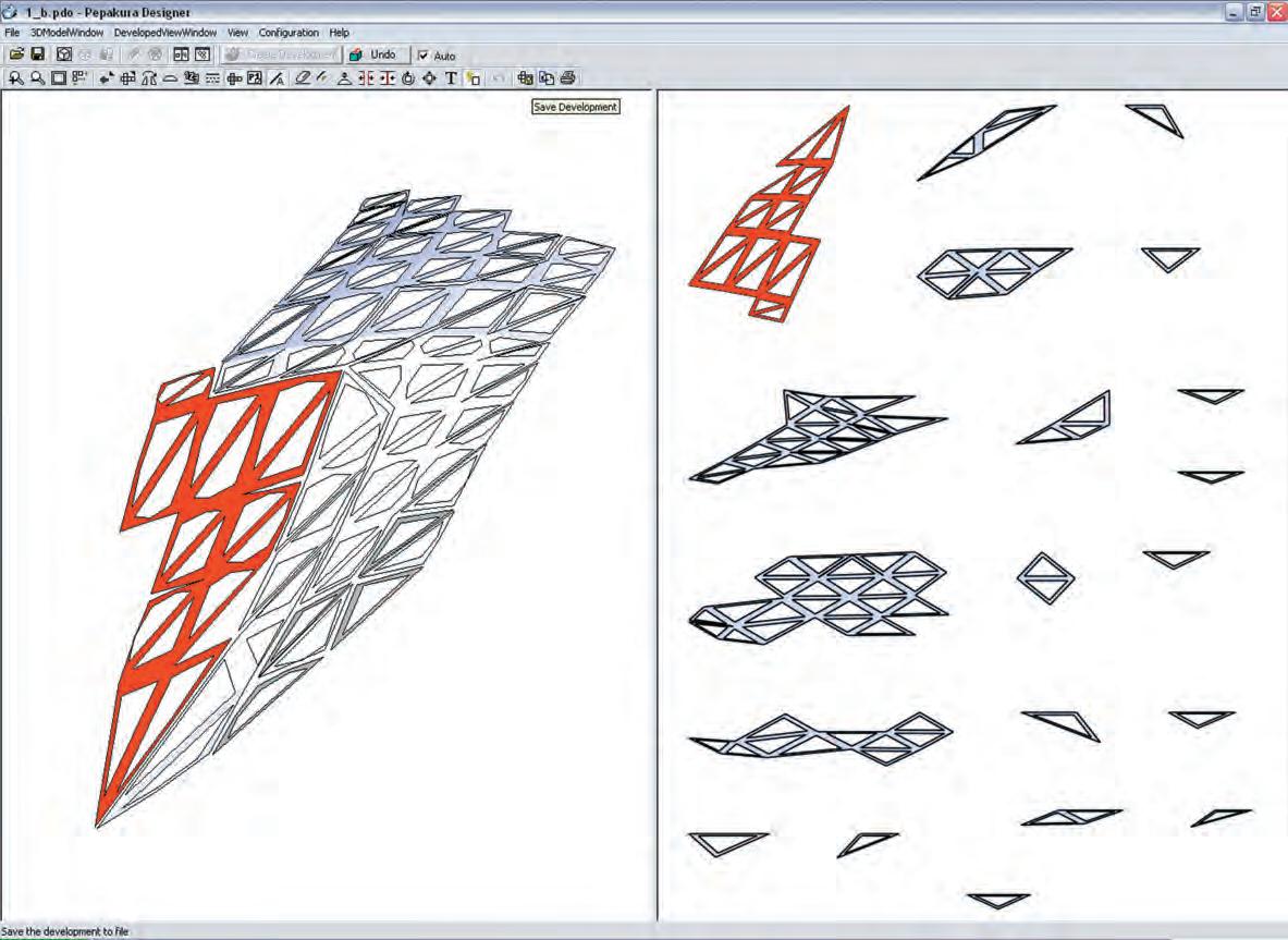
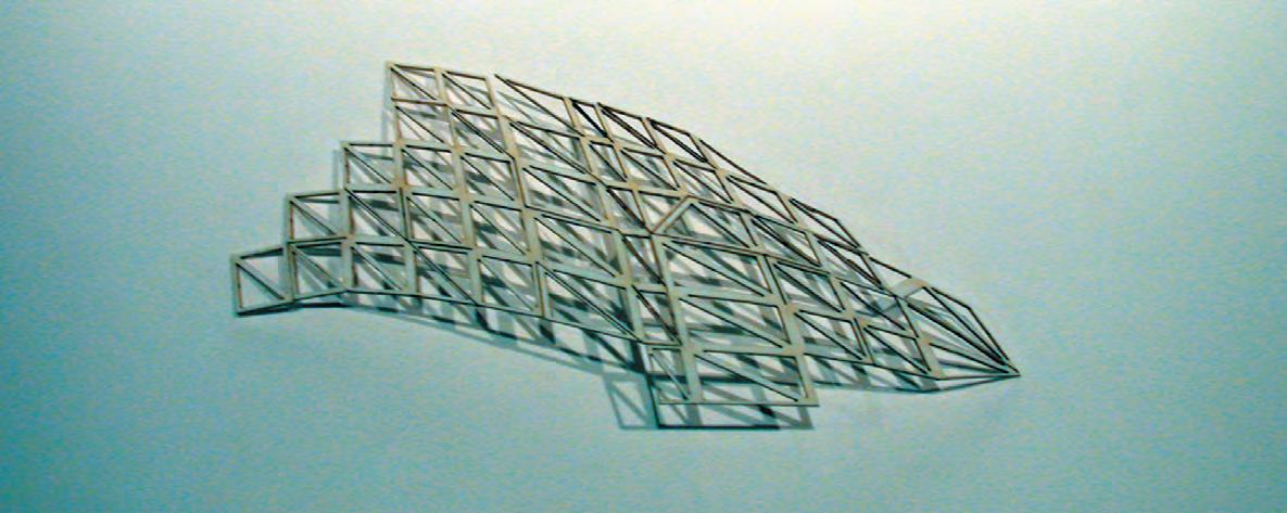
Phenotype Analog model
Unfold process in “Pepakura” unfolding software. Piece of model in 3 stages
The building process is defined as the translation from the digital to the material realm, where the 3D shape of the model is deduced into a flat configuration, to take it back to 3D later through the assembly process.
The steps needed for the analog model preparation requires the use of four different softwares, first Generative Components, where the global and components geometry where separately constructed and later assembled together. Then the geometry is exported into Rhino, using IGS format. In Rhino is divided into 36 different pieces, each of them is exported as a separated DXF file. Then each of the pieces is opened in Pepakura, unfolded and saved as an EPS file. Each of these files is opened in Illustrator and saved as a DWG. Finally all the 36 DWG files are combined together into on file in Rhino, where the pieces are labeled and organized to send them to the laser cutting procedure as a DWG file.
As is shown in the picture at right, Pepakura software is used as a guidance in order to recognize the different parts needed to put together each of the 36 pieces, where flat components (right hand side window) are related to the 3d piece (left hand side window) as you click them.
Pepakura software “screenshot”, showing two stages for the same piece, 3D and unfolded Same piece back again to 3D, this time as a piece of the maquet.
092
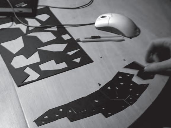
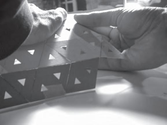
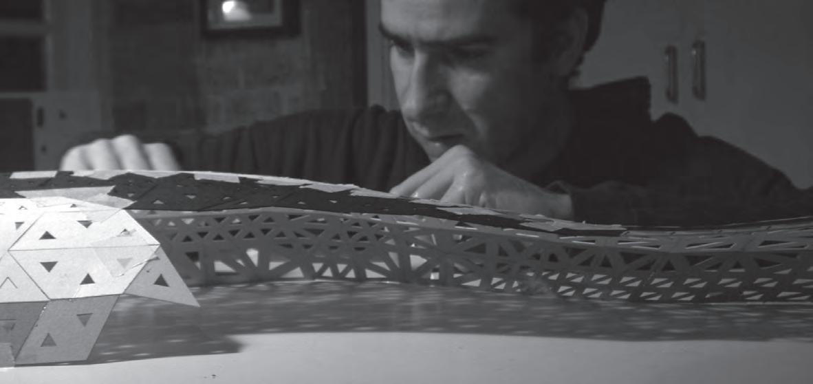
Phenotype Analog model
Assembly proccess
The assembly for this kind of models is a very interesting process. It is quite surprising to see how small/flat/isolated pieces start to achieve three-dimensionality as they are attached together. By doing this, their original geometry taken from the digital real appear in the physical world. In general mankind have been always interested and looking into ways to rationalize complex three dimensional geometries, like human anatomy, buildings, sea shells maps of the world etc... Nowadays computers and their associated construction technologies allow the simple rationalization of complex tasks. This fact have opened and stretched the borders of architecture and another design related activities to unsuspected limits, leading to tremendous advantages to the designer.
The CAD/CAM technologies used to construct this model are at the same time the most appropriate technologies in order to construct the system in real scale, where each isolated component is formed from flat sheet. Later on as the different components are assembled together the global geometry takes form, just as it happens in the maquet. Thus considering the gaps in scale the two processes can be clearly related.
The images on the left are showing gradually how the process from the flat to the three-dimensional shape is completed.
“The CAD/CAM technologies used to construct this model are at the same time the most appropriate technologies in order to construct the system in real scale”
 1 Assembly process of one of the 36 pieces
2_Assembly process between pieces.
3_As the separete pieces are attached together the model gets it shape naturaly 4_Side view of the completed model
093
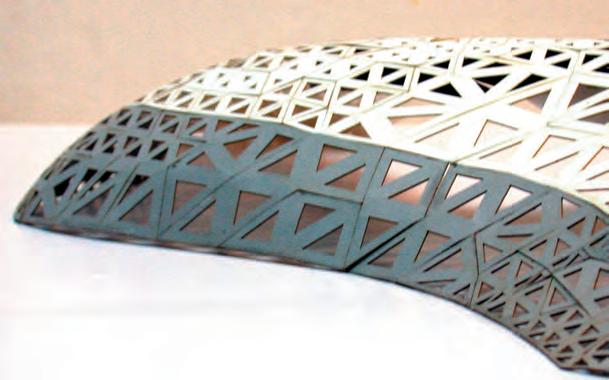
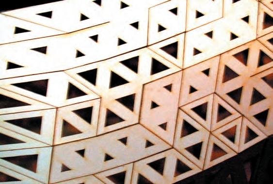


Phenotype Sample building Analog model
Surface details and light patterns observation
Despite the fact that these images are not considered as a rigorous light test procedure, they are showing some tendency on the light behaviour as passes through the envelope, such as the overall decrease in the amount of light and the clear incidence that the different components on the surface level have in the light patterns observed inside the building. Looking the shadow patterns at floor level can be clearly read where the borders between permeability zones are located at the surface. Also can be observed the difference between the light qualities at surface level on the outside of the building (strong contrasted light) and the light quality at the interior of the building (more smooth an even with diffuse borders).
The major impediment to make real light tests with this model is the fact that this lacks thickness, since the thickness of the components plays a key role in the light permeability of the system. This issue is addressed at a diagrammatic level.
 View of north facade of the envelope from the east
Detail of differntiated surface
Partial viewfrom the outside of unfinished envelope and light pattern at floor level.
Light modulated
projected
floor level
Difuse
Diferentiated light pattern at the inside of the building floor level
by envelope
at
(building interior).
borders.
094
Overall zone of high light exposure
50% of light permeability
Overall zone of low light exposure
50% of light permeability
Overall zone of medium light exposure
50% of light permeability
25% of light permeability
75% of light permeability
Static Sun light chart in relation to the building
After the definition of the phenotype, the sample building is taken into a series of observations in order to analyze how it behaves in relation with the environment and explain further its performance.
In this diagram, the building is divided in three major zones taken in relation to light permeability; in each of these zones a section of the envelope is drawn making an emphasis in the thickness of the shell. In each of the sections is high lightened the different light permeability degrees defined by the opening of the components nested in that particular area of the envelope.
25% of light permeability
75% of light permeability
Sun Transit
25% of light permeability
N
C_3.3.1 Light system observations 095
Light system observations
Aiming to be more specific, in each of the three sections is deduced the light penetration. This procedure is repeated to each of the most representative sun positions trough the year, equinoxes and summer and winter solstices.
In the diagrams, the angle of the sun position in relation with building and the individual components, will define which cells are trespassed directly by sun light and which others will behave as a source of indirect light.
Summer solstice sun chart Equinox sun chart Light penetration Summer solstice penetration, 80.27 degrees Equinoxes penetration, 57 degrees Direct light Indirect light Winter solstice sun chart 12 11_13 10_14 9_15 8_16 7_17 6_18 9 73 80.27 ° zenit 6 7 8 9 10 11 12 11 10 9 8 7 6 147.00 ° 12 11_13 10_14 9_15 8_16 7_17 6_18 33.00° 57 00 ° zenit zenit 6 7 8 9 10 11 12 11 10 9 8 7 6 147 00° 12 11_13 10_14 9_15 8_16 7_17 6_18 zenit 6 7 8 9 10 11 12 11 10 9 8 7 6 14700 ° 5700° 33 00 ° Winter solstice penetration, 33 degrees Direct light Indirect light Direct light Indirect light
Hight permeability Low permeability Medium permeability Hight permeability Low permeability
permeability
permeability Low permeability
permeability 096
Medium
Hight
Medium
Direct / Indirect light incidence
In this page is more specifically shown the two different kinds of light (direct or indirect) penetration in accordance with the component position trough the surface. The direct light will have an influence on the light pattern at floor level, and at the other hand the indirect light is reflected into the interior space, given then a particular -more soft- light quality to the building.
It is also shown the range of angles in light penetration for one component, this will influence the light choreography at floor level, where the pattern will have a transitional behaviour as the sun changes it position in relation with the envelope.

Direct
Indirect light permeability, skylight effect
Light pattern at floor level inside the building Component, Top Component, Side Component, Bottom Component, Right
of light permeability tolerance : Over 60 degrees
Angle
Shell thickness variation in relation with components location trough the surface
097
light permeability Light system observations
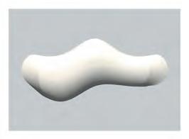
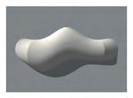
Daily choreograohy, transit of contrastefd light patches inside the building at floor level.

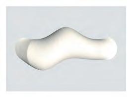
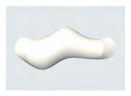
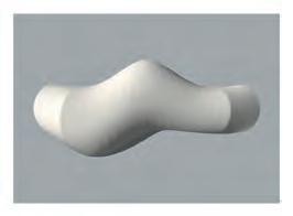
This procedure is conduced using the same renders used to predict the light exposure at surface level. In this case the aim is to identified the zones of most direct light incidence to different times of the day inside of the building at floor level.
Due to the characteristics of the component in relation to their permeability to direct light, the envelope is more likely to allow the pass of direct light when the sun is perpendicularly hitting the surface. Assuming this, the zones showed in this images are the predictions of that attribute for different times of the day during . This procedure is repeated for the Equinox and both solstices
9am 6pm 9am 12am 12am 12am 12am 3pm 3pm 6pm 6pm 9am 9am 12am 12am 12am 3pm 3pm 6pm 9am 12am 3pm 6pm 9am 12am 3pm 6pm
Equinoxes daylight choreography inside the building at floor level.
Summer Solstice daylight choreography inside the building at floor level.
system observations 098
Light


Winter Solstice daylight choreography inside the building at floor level.
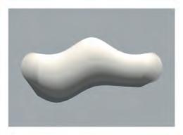
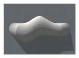
Light system observations
Combined choreograohy of contrasted light patches inside the building at floor level.
The outputs gained from each of the daily procedures are combined together in an overall sunlight choreography inside the building at floor level. Defining then the most exposed areas through the year. This pattern is taken into section view, where the combined reading is showing the tendency of direct light influence in the inner volume of the envelope. The angle of the light used for this graph is the light angle described at the equinox, since is an average between the different angles of light incidence through the year.
Overall light choreography trough the year
“This pattern is taken into section view, where the combined reading is showing the tendency of direct light influence in the inner volume of the envelope”


9am 12am 12am 3pm 3pm 6pm 6pm 6pm 9am 12am 3pm 6pm 9am 12am 3pm
A B C Section A Section B Section C
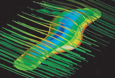

Considering the degree of differentiation achieved with the system, and the potential in terms of the complex performance of the envelope, the ventilation settings proposed are rather simple. Nevertheless they are tuned with the climatic characteristics of the Mediterranean weather, and more in particular with the characteristics of the site.
These diagrams are showing the configurations for the most characteristic climatic conditions trough the year, defining then three different ventilations settings and therefore permeability levels.


chart
m/s
associated with rain J F M A M J J A S O N D N S N S
Summer
Fall/Spring
Winter
open zones open zones open
incidence in the site and building C_3.3.3
observations south wind south wind south wind south wind south wind south wind north wind north wind north wind
Wind
10
Winds
Ventilation settings
setting; High degree of ventilation
settings; Average degree of ventilation
setting; Low degree of ventilation
zones Wind
Ventilation settings
100
Water container cell empty, porosity open
Sunny and warm climatic conditions
Overall permeable envelope


Water container full, starts procces of irrigation
Water moves through capillaries


Wet and cold climatic conditions
Air permeability cycle
This sequence is showing in the simplest way the different stages of the cycle of water in the system and its consequences on the envelope configuration, therefore in the ambient conditions at the inside of the building.
The cycle starts with the system dry. The containers are empty, the muscles are relaxed, the porosities are open and the envelope is permeable.
When it is raining, the system starts to work. First the water is collected (as it is collected in any roof, by the slope) and taken by gravity to the containers, due to the capillary principle the water moves trough the veins towards the muscles, then they start to soak water, the swellgel begin its expansion.
As the muscles are stimulated they perform tension. Now the muscles are contracted, the porosities are closed and the envelope is sealed preventing the water to go trough the envelope into the building.
Once that the rain stops, and the dry conditions are back, the systems starts to release water as vapor, the muscles starts they relaxation process, the porosities came back to their open configuration and the envelope is permeable again.
The system has completed the cycle and now it is ready to start another the cycle again.


Container releases water into the system, porosities close
Overall sealed envelope


Wet and cold climatic conditions
Details of container and how the water moves from there into the muscles

C_3.3.2
Pneumatic system observations
101
Zones of daily exposure to direct light trough all the year.
Transit of templates zones of non direct light exposure.
Traces of light choreography for programmatic distribu-
choreography tion
Using the observations of light penetration into the building, two main kinds of ambient are identified. One is defined by the zones that have the major sunlight coverage trough the year, where every at some time of every day during the whole year they are exposed to direct light that surpasses the envelope. The other is defined by transitional zones areas where there is less light exposure and is variable in accordance with the season of the year. Each of these two ambient zones is sub-divided in another two zones, describing then four partitions in the building plan.
This ambient zonification is used to inform the programmatic organization inside the building.
Equinoxes
races
C_3.3.4 Programatic Lay out
Summer Winter
102
Choreography trough the year
Programatic lay out informed by ambientat subdivision at the inside of the envelope
Zone 1: Gallery, courtyard, interior garden
Zone 2: Stage, conference room
Zone 4: Exhibition hall Pacific ocean
Zone 3: Administration, cafeteria, restaurant, shop, services
Zone 3: Medium/Hight light exposure 50cm above ground floor
Zone 2: Low light exposure with transit of patterns through the year. One meter above ground level
Zone 1: Hight light exposure and air permeability, interior garden, fine boundary between interior and exterior. Ground floor level. Public zone
Zone 4: Average light exposure with transit of patterns through the year. 50cm above ground level
Access Access Programatic Lay out N
City center
Plan
Section
View
103
104
Chapter four Closure
Material system
The mechanical system investigated has successfully proved that using two main components for the structure (cells and muscles) it is possible to achieve a huge range of different and specific dynamic behaviours. In relation to the “passive / reversible / dynamic” interactions of the structure, all the sets of experiments have evidenced the dependency of the system on its static or locked points. Thus the dynamic parts of the pattern are always attached to the secure parts. The input for the dynamic devices is water extracted from the environment where the system is placed. In relation to this, the key to this investigation is how to use, in an instrumental way, the one single physical interaction of the pneumatic devices developed. Therefore the proper combination of geometry, dynamic devices and environment will produce an efficient climatic envelope.
Collective behaviour
The individual reactions are inherent to the cells, and they promote local topological changes, switching in a reversible manner from open to close. Nevertheless if this behaviour is multiplied by several components nested in the system, the result is an overall topological mutation, and as a consequence the overall permeability of the system changes. The whole envelope permeability is informed by the components, more specifically by the partial opening of the porosities. In accordance to this, the shell is conceived as a wing shaped building, where the flow of air is accelerated, and to some extend controlled and consequentially used as a passive ventilation agent.
In relation to the light control system, the global geometry and its relation to light exposure will inform back the local scale, defining the degree of opening (transparency) of each individual component. This information process is set in accordance to light conditions predefined for the building space. Therefore, potentially there are several light permeability setups; these different associations are organized in accordance to light conditions at the site, the program of the building and finally the ambient intended to generate at the interior of the envelope.
Sample building
The grid shell structural typology of the sample building is informed by the material system, the interrelation of the material system with the environment defines global shape and tessellation logics. The program and the ambient conditions intended to generate inside the building are setting the population strategy, therefore the light and air permeability layouts.
Relevant observations made on the sample building are delivering important statements about the performance of the envelope. On the one hand, the light projected over the surface of the envelope is manipulated in order to control its trespass trough the shell generating a particular light pattern at floor level and a specific climatic ambient in the internal volume. On the other hand the ventilation settings have been tuned in accordance to specific meteorological conditions at the site, furthermore they change together with the seasons of the year in accordance to the wind directionality and the oscillation of temperatures.
Process no building
The thesis is structured in two main parts, analog and digital. Firstly the physical experiments put out some mechanic properties that are investigated into the digital realm. These properties are observed in several manners and finally organized with the aim of defining a “Genetic design engine”. The behaviours extracted from the material system combined with the particular environmental characteristics of the site where the building is placed will have as a consequence one only output or sample. This is the “phenotype” while the design process is the “genotype”. In the context of the investigation the final “phenotype” output is a vehicle to understand, explain and prove the genetic information contained in the thesis.
Finally, if the genotype is successfully proved as a valid design process, the procedure can be repeated in different environments. The process (DNA) will be the same. Nevertheless the geometry and organization of the structure (phenotype) will be always different. Assuming this, the aims of this thesis it is not focused on the design of a building. The ultimate aim is to design a smart procedure that can be applied in different environments and with different purposes, generating a diverse family of phenotypes tuned with the specifics characteristics of their surroundings.
1
Conclusions
105
The further development intended for this research is based on making more specific interrelation between the informing entities that are defining the geometrical and kinetic characteristics of the actual system. So far the work presented in this thesis have been dealing successfully with the bigger hierarchical levels of the different sub systems (light, air and water). Nevertheless if the project is developed further, more specific interrelations and definitions can be undertaken. However in order to achieve this, even more specific data is required, for instance computer fluid dynamics simulations for the interior space of the envelope. In addition to this, another important step further can be made by constructing a final digital model of the sample building, in this case taking into account the thickness of the envelope. Having a more realistic digital model would allow to predict with higher accuracy the light behaviour inside the building, also due to the parametric characteristics of the diaphragms different settings can be tried by changing the degree of opening in the different cells.
In relation with the watering system, another step further would be the definition of the irrigation zones to the already defined 15 active sub zones, by doing this the whole envelope can be subdivided in another manner and furthermore will allow the identification of the specific role for each individual cell.
Finally, despite the fact that they have been addressed conceptually, the issues related with the real implementation and construction processes for the material system haven not been undertaken as seriously as is required in order to have a real final product. Therefore this topic it is open to revision, and then supplementary definitions could be made in topics such as: Materiality, CAD/CAM processes, transportation, assembly and finishings.
Further development
106
Finding form
IL 38 Diatoms II, Shells in nature and techniques III
IL 28 Diatoms I, Shells in nature and techniques
AA files 52
AD Architectural Design, Emergence: Morphogenetic Design Strategies
AD Architectural Design
Frei Otto, Bodo Rasch, 1995, 2001 edition.
Johann-Gerhard Helmcke and Ulrich Kull, 2004
Johann-Gerhard Helmcke and Ulrich Kull, 2004
2005
May 2004
March 2006
Desmonstrating science with soap films, David Lovett, 1994
Structure in nature is a strategy for design,
Peter Pearce, 1990
The Kelvin problem, Foam structures of minimal surface area, Denis Weaire, 1996
Aerospace design, Aircraft, Space craft and the art of modern flight
Aircraft
Architecture for sports
Exhibition pavilions
Hallen Expo Halls 8+9
Architecture of Eden
Lightness: the inevitable renaissance of minimum energy structures
Book of skin
Double-skin facades: integrated planning
Anthony M. Springter, 2003
David Pascoe, 2003
Peter Sturzebechen, Sigrid Ulrich, 2001
Moises Puente, 2000
Von Gerkan, Marg and Partners, 2000
Hugh Pearmen, 2003
Adriaan Beukers, Ed van Hinte, 1998
Steven Connor, 2003
Eberhard Oesterle
Naturally ventilated buildings: building for the senses, economy and society 1997
Environmental sustainability: the challenge of awareness in developing societies
The Times concise Atlas of the World, eight edition
Buckminster Fuller: antology for the new millennium
Zuq Musbih
2001
Thomas T.K. Zung, 2001
Bibliography and references
107


 1 Assembly process of one of the 36 pieces
2_Assembly process between pieces.
3_As the separete pieces are attached together the model gets it shape naturaly 4_Side view of the completed model


 View of north facade of the envelope from the east
Detail of differntiated surface
Partial viewfrom the outside of unfinished envelope and light pattern at floor level.


