HydraulicFracturePotentialduringDrillinginDams

Environmental&EngineeringGeoscience,Vol.XXIX,No.1,February2023,pp.3–16 7
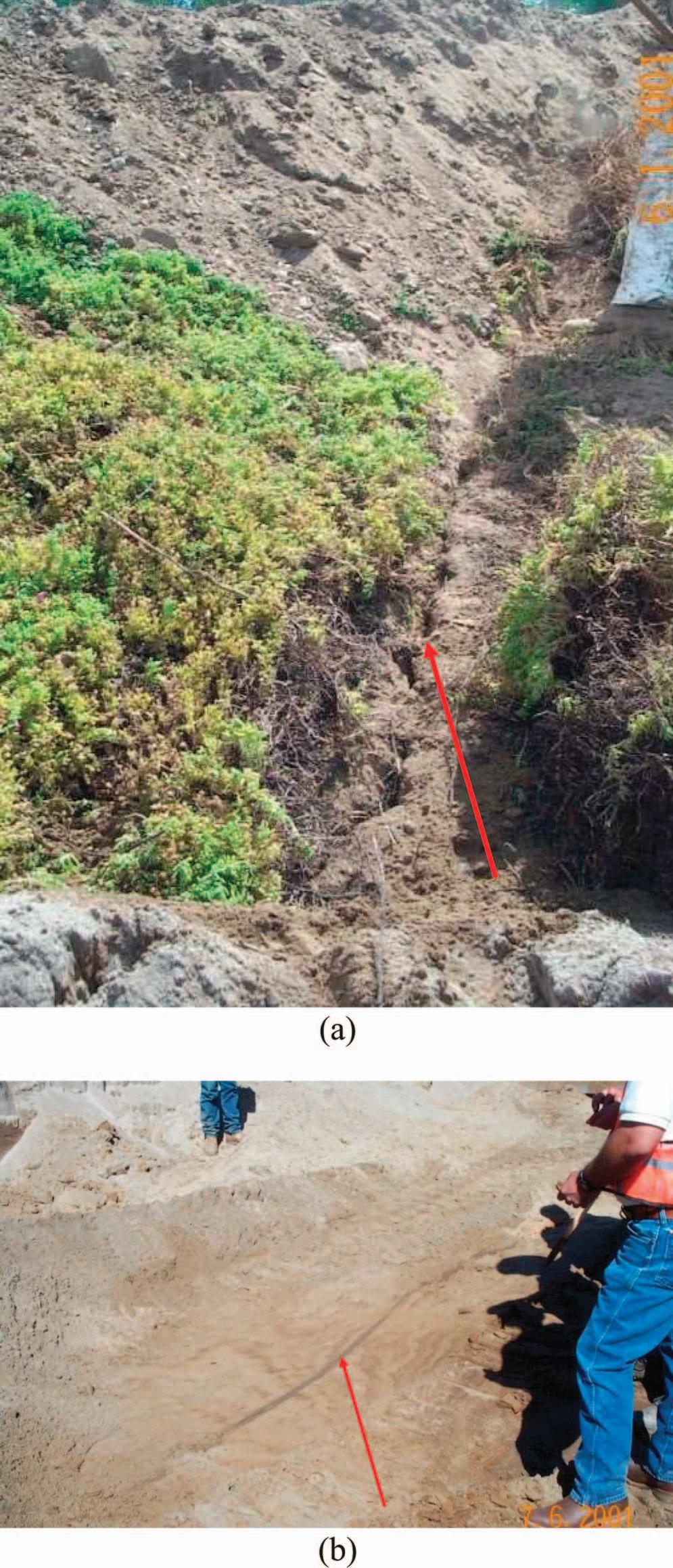
Figure6.(a)Cut-offwallconstructedinMudMountainDam,WA(USACESeattleDistrict).Noteverysteepandnarrowrockvalley,which resultsinlowconfiningstressintheembankment.(b)Longitudinalcrackthatdevelopedintheworkplatformduringconstructionofthe cut-offwall.(c)Verticalcrackinthesideofacut-offwallpanelexcavation.
Figure6.(continued)
drilling(HDD)tocausehydraulicfracture.The groutleaksandfractureswereeasilyidentifiedwith thered-dye-coloreddrillfluid(Figure9).

Duetothesignificantnumberofknownincidents, wecanconcludethatitisnotrareforhydraulic fracturestooccurfromintroductionoffluidsinto embankmentsandtheirfoundationsduringdrilling, grouting,orunbalancedslurryconstruction.Intheauthor’sopinion,itisalsolikelythattherearemanymore casesthathavenotbeenreportedduetoamisinterpretationofdrillfluidlossorexcessivegrouttakes.
ESTIMATINGHYDRAULICFRACTURE PRESSURES
Severalmechanismsforhydraulicfractureinsoils havebeenproposedbydifferentresearchers.Aliteraturereviewrevealedthattherearemanydifferentconceptsandmodelswithwhichtoestimatedamaging fracturepressuresinsoils,including tensilestress, undrainedshearstrength, unconfinedcompressionstrength,
Figure7.(a)Sketchshowingthelocationofahydraulicfracture thatoccurredontheGreenPocketLevee.(b)Photographshowing aslurry-filledhydraulicfracturefoundinanexcavationoftheembankment.

elastictheory, linearelasticfracturemechanics, empiricalformulas,and cavityexpansion.
Thesemodelsrangefrompracticaltoverytheoretical.Inthisstudy,itwasdesiredtodetermineifthere wasapracticalmodelthatwouldgivereasonableresults.Sherard(1973,p.273),statedthat,“Fromapracticalstandpoint,acrackmaybecausedtoopenona givenplaneiftheeffectivestressactingontheplane goestozero;thatis,ifthetotalstressontheplaneis equaltoorlessthanthewaterpressure(providedthe soilcannotwithstandtensilestress).”
Documentationintheliteraturerelatedtofieldhydraulicfracturetesting(Bozozuk,1974;Calcagno, 1983;ChenandZhang,1989;Hamoucheetal., 1995;andSherard,1973)revealedthatthepressurerequiredtoinitiatehydraulicfracturewasalwayssomewhatgreaterthantheminorprincipal stress.Thefieldtestresultsshowedthatthefracturepressurewasapproximately300to3,000psf
Schaefer
8 Environmental&EngineeringGeoscience,Vol.XXIX,No.1,February2023,pp.3–16
(14to144kPa)greaterthantheestimatedminorprincipalstress,whichsupportstheideathat thesoilstrengthcontributestothefracturepressure resistance.
TheapproachtakenbyAndersenetal.(1994)was basedonthegeneralprinciplethathydraulicfracturingcanoccurifthegroutpressureexceedstheminorprincipalstressplusthetensilestrengthofthe soil.ThiswassupportedbyastudybyAlfaroand Wong(2001),whereinthevariousconceptswereinvestigatedandcomparedtolaboratorytesting,and thetensilestrengthapproachbestapproximatedlaboratorytestsforhydraulicfracture.AdditionalbackgroundonhydraulicfracturingcanbefoundinSherard(1970),Sherardetal.(1972),Sherard(1986),and Bjerrumetal.(1972).
Becausetensilestrengthisnotcommonlydeterminedforsoils,itisproposedthattheundrained strengthofthesoilcanbeusedtoreasonablyapproximatethetensilecapacityofthesoil.Hydraulicfracture ofclaysoccursinanundrainedloadingconditionbecausethereisaquickloadactingonanimpervious soil.Severalresearchershavepublisheddatafromlaboratoryhydraulicfractureteststhatalsoincludedinformationontheundrainedstrengthofthesoil.The author’sevaluationofthemeasureddatafoundinthe literaturereviewrevealedthattheboreholefracture pressurecancloselyapproximatethemeasuredfracturepressureinthelaboratoryusingtheminimum principalstressplustheundrainedstrengthofthesoil intermsoftotalstress. P

which,fornormallyconsolidatedsoils,wouldreduce to:
Ifenoughdatawereprovidedinthepapers,theresultswerereplottedandoverlainwiththeproposed predictionfromEq.1.Figures10and11showthatthe predictionfromEq.1agreeswellwiththelaboratory

HydraulicFracturePotentialduringDrillinginDams
Figure7.(continued)
f = σ3 + σ3 tanφu + cu , (1)
Pf = σ3 + cu . (2)
Figure8.(a)Asurfacecrackand(b)anexcavatedslurry-filledhydraulicfracturecrackfoundontheAmericanRiverLeveeduring constructionofaslurrywall.
Environmental&EngineeringGeoscience,Vol.XXIX,No.1,February2023,pp.3–16 9
hydraulicfracturetestsandhighlightstheimportance oftheundrainedshearstrengthofthesoil.
DELFTCAVITYEXPANSIONEQUATION
TheHDDindustrycommonlyusestheDelftCavity ExpansionEquation.Thecavityexpansiontheorywas firstdevelopedbyVesic(1972)andthenfurtherdevelopedforuseinHDDprojectsbyresearchersatDelft Geotechnics,LugerandHergarden(1988).Thetheory isthatastheannularfluidpressureincreases,theboreholeradiuswillexpand.Initially,thedeformationwill beelastic,butasthepressureincreases,thedeformationwillbecomeplastic.Asthezoneofplasticdeformationincreasestothegroundsurface,blowoutwill occur,anddrillingfluidwillflowtothesurface,creatinga“fracout”or“inadvertentreturn.”USACEguidancedocumentEM1110-2-2902—Conduits,Pipes, andCulvertsAssociatedwithDamsandLeveeSystems(USACE,2020),describesseveralissueswiththis equationandapproach.Theprimaryissuesare(1)the equationisusedtolimitpressuretopreventdrilling fluiddischargeonthesurfaceratherthanpreventing theinitiationofhydraulicfractureand(2)thethe-
oryisbasedonisotropicstressconditions,whichalmostneverexistinrealsoils.Fordamandleveesafety, weareconcernedwithpreventingdamage,notjust fluidreleaseonthesurface.However,forclays,ifwe simplifytheequationbyassumingundrainednormally consolidatedsoilconditionsandtheminorprincipal stressisusedinsteadoftheisotropicstress,theDelft equationreducesdowntobeequivalenttoEq.2given above.

USACEREGULATIONER1110-1-1807
TheapproachusedbyUSACEinER1110-1-1807— DrillinginEarthEmbankmentDamsandLevees(USACE,2014)shouldbeimplementedwithintheprofessionalpracticeandfollowedwheneverdrillingorother invasivetechniquesareusedondamorlevees.Ifpossible,theuseofdrillingfluidsshouldbeavoidedin orneardamorleveeembankments.Ifdrillingfluids mustbeusedduetothedrillingobjectiveorthesubsurfaceconditions,theDrillingProgramPlan(DPP) mustcontainananalysiswithcalculationsforthepotentialtocausedamageandthemeasuresthatwillbe usedtominimizerisk.ForUSACEdams/levees,all DPPsthatproposetheuseoffluidsmustbereviewed bytheStandingCommitteeonDrillingandInstrumentation,ledbytheUSACEGeotechnical,Geology, andMaterialsCommunityofPracticeLeadandapprovedbytheDamSafetyOfficerortheLeveeSafety Officerattherelevantdistrict.Thetotalminorprincipalstressplustheundrainedstrengthofthesoilshould beusedtoestimatethehydraulicfracturepressure. TheUSACEregulationdoesnotrecommendafactorofsafety.Designersshouldselectanappropriate factorofsafetybasedontheimportanceofthestructureandlevelofuncertaintyintheanalysis.Itwould bereasonabletouseafactorofsafetyinthe1.3to 1.5range.
CONFININGSTRESS
ThefirstparameterinEq.1andEq.2isthetotalminorprincipalstress.Todeterminethisforflatground conditionswithnormallyconsolidatedsoils,thesteps are:
1.Determinethesoilunitweights.
2.Estimatetheporepressureusingseepagemodeling ormeasureddatafrompiezometers.
3.Calculatetheverticaleffectivestress.
4.Estimate k0 byusingtheequationinJaky(1944), whichgivestherelationshipbetweenthemajorand minoreffectiveprincipalstressesas
Schaefer
Figure9.Red-dyedslurry-filledhydraulicfracturecrackoverahorizontaldirectionaldrillingboring.
k0 = σ 3 /σ 1 = 1 sinφ . (3) 10 Environmental&EngineeringGeoscience,Vol.XXIX,No.1,February2023,pp.3–16
However,therealconditionsfordamsandmanyleveesaremuchmorecomplicated.Theconfiningstresses cannotbeaccuratelyestimatedbysimplecalculations duetothefollowingissues:
Embankmentsalwayshaveslopedgroundconditions.
Majorandminorstressesarenotalwaysverticaland horizontal.
Theupperzonesoftheembankmentmaybeoverconsolidatedduetolocked-incompactionstresses, whilethelowerzoneswillbenormallyconsolidated becausethesoilweightisgreaterthanthecompactionstresses.
Thephreaticsurfacecanvarysignificantlyacrossthe coreofadam.
Irregularrocksurfaces,pinnaclesandslots,steep abutments,overhangs,conduits,concretedamcontacts,anddifferentialsettlementwillallcauselocalizedlowconfiningstressconditions.
SeeSherard(1986)foragooddiscussiononthespecialconsiderationsforlow-stresszonesthatcontribute tohydraulicfracturing.
Withmodernnumericalanalysistoolssuchas SIGMA/W,FLAC,andPLAXIS,atwo-dimensional modelcanbedevelopedtoestimatethestaticstresses inanembankmentdamatthelocationoftheproposed drilling.Inspecialcaseswithcomplexgeometry,threedimensionalmodelsmaybeappropriate.Thiswilltypicallyrequireevaluatingdifferentsections,including bothlongitudinalandtransversesections.Thegeometryofthemodelshouldbebasedonconstruction recordsandanyavailableboringdata,sothefoundationgeometryandembeddedstructuralfeatures,such asconduits,areproperlyincluded.Multiplepoolelevationsandpiezometricconditionsmayneedtobe consideredbasedonthepotentialforpoolfluctuations.Alinearelasticsoilstrengthmodelcanbeused. Theunitweightofthematerials,anestimateofPoisson’sratio,andcharacterizationofgroundwaterconditionsaretheprimaryvariablesrequired.Poisson’sratio isusedinthemodeltodeterminetheratioofhorizontaltoverticalstress(k0 ).
Oncethemodelisconstructed,itisloadedwithselfweight(gravity),andstressesarecalculated.Contour plotsofdepthversusstressprofilesofthetotalminimumstressescanbedeveloped.Thisanalysiswillprovideanapproximateestimateofthestressesinthedam

HydraulicFracturePotentialduringDrillinginDams
Figure10.LaboratoryhydraulicfracturetestresultsonfivesamplesfromMoriandTamura(1987)comparedtoproposedpredictionequation.
σ 3 =
σ 1 (4)
5.Calculatethehorizontaleffectivestress,
k0
6.Addtheporepressuretodeterminethetotalhorizontaleffectivestress.
Environmental&EngineeringGeoscience,Vol.XXIX,No.1,February2023,pp.3–16 11
andfoundation.Moredetailedevaluationcanbedone usingmultistagesequencemodelingandmorerigorous materialmodels.SeeMcCookandGrotrian(2010)for proceduresformorerigorousmodelingforhydraulic fracture.Multiplesimplifiedrunscanbeperformed parametricallybyvaryingtheinputparameterstoestimatetherangeofstresses.
MEASUREMENTOF INSITU STRESS

Itispossibletomeasure insitu stressusingtools suchastheself-boringpressuremeter(Benoit,1995).
Theself-boringpressuremeterisconsideredtobethe mostreliablemethodformeasurementoflateralstress insoils.Thepressuremeterisplacedinthebottomof aboringandadvancedusingarecessedcuttingbit.
Afteradvancementtothedesireddepth,testingisdelayedtoallowforthedissipationofporepressure.
Themembraneisthenpressurized,andtotalpressure
versuscavitystrainismeasured.Thetotalhorizontal stressisdeterminedateachstrainarmbyinspectionof thetotalpressureversuscavitystrainplots.Thepressureatwhichthemembraneliftsoff(beginsdeforming thesoil)isequaltothe insitu totalhorizontalstress. Schmertmann(1985)providedadditionalinformation on insitu lateralstressandmethodsformeasurement. Measurementof insitu stresscanreallyonlybeused asaconfirmationoftheestimatedstresses,sincea boringusingdrillfluidmustbeperformedtodothe measurement.
DRILLINGNEXTTOCONDUITSANDSTEEP ROCKABUTMENTS
Cautionshouldbeusedbeforedrillinganyboringsnexttoconduitsorsteeprockabutments.Numerousincidentsofdrillfluidlossadjacenttoconduits
Schaefer
Figure11.Laboratoryhydraulicfracturetestresultsfromfourotherstudies(SeedandDuncan1981;LoandKaniaru,1990;Yanagisawaand Panah,1994;andAlfaroandWong2001)comparedtoproposedpredictionequation.
12 Environmental&EngineeringGeoscience,Vol.XXIX,No.1,February2023,pp.3–16
orabutmentshaveoccurred.Stressesaroundconduits canbeverylow.Itispossibletohavetensilestresses adjacenttoconduitsduetoarchingeffects,asdemonstratedinaresearchreportbyCasagrandeandCovarrubias(1970)fortheUSACEWaterwaysExperiment Station.Iftensilezonesarepresent,thentheuseofany drillingfluidwilllikelycausehydraulicfracture.Figure 12showsacommonconditionwhereoutletworksconduitswereconstructednearasteeprockabutment.In theareamarkedbytheredarrowinFigure12,arching ofthesoilswilloccur,andtheconfiningstressesinthe areabetweentherockabutmentandtheconduitwill beverylow.
UNDRAINEDSTRENGTH
ForthesecondpartofEq.1andEq.2,the undrainedstrengthofthesoilisrequired.Thiscanbe determinedfrompreviouslaboratoryorfieldtestingor correlationstoindexproperties,oritcanbeestimated usingcriticalsoilmechanics.Aconservativeestimate canbeobtainedbyassumingtheembankmentdamor leveeisnormallyconsolidated,andEq.2canbeused.

Thisassumptionisvalidinmostcases,exceptin theuppersoilzones,wherethelocked-incompaction stressesaregreaterthantheoverburdenstress,andthe undrainedstrengthwillbemorethanestimated.Ifno previoustestingforundrainedstrengthisavailable,for normallyconsolidatedclays,theundrainedstrength ratiototheverticaleffectivestresscantypicallybeestimatedas ½ sin φ orintherangeof0.22to0.25. Equation5canthenbeusedtoestimatetheundrained strength.
Figure13showsdamagetoabottomoutlettunnel linercausedbyexcessivegroutpressureswhenrefusal pressureadjacenttothetunneldidnotconsiderthetotalpressure.

PRESSUREMEASUREMENT
Whencomparingestimatedfracturepressuresto pressuresinthefield,therelevantvaluetouseisthe totalpressure.Thetotalfluidpressureistheinitial porepressureplustheadditionalpressureappliedby thecolumnoffluidorgrout.Pressuremeasureddown theholeinthefieldwillbethetotalpressure.Groutingprojectstypicallyuseeffectivepressurestomonitor groutingprograms.Thisisappropriatefordeterminingtheeffectivenessofthegrouting.Inorderforthe grouttobepushedintosubmergedrockjoints,theinjectionpressuremustfirstovercomethe insitu groundwaterpressure.Theadditionalpressureistheeffectivepressure.However,totalpressureshouldbeused toevaluatehydraulicfracture,andeffectivepressure shouldbeusedtoevaluategroutingeffectiveness.Also, whendeterminingtheloadappliedtounderground structures,thetotalpressureshouldbeevaluated.
Onewaytoimproveourabilitytomonitorpressuresiswiththeuseofinstrumentedpackers,which candirectlymeasurethetotalgroutorwaterpressure directlyatthetopofthegroutorwaterpressuretest stage.Detailsofaninstrumentedpackerdevelopedby ACTforuseontheRoughRiverDamprojectcanbe foundinIvanovetal.(2017).Itisalsocommonfor HDDdrillingequipmenttohavepressuresensorsat thecuttingheadtodirectlymeasurethedrillfluidpressure.Forstandardgeotechnicaldrilling,directmeasurementoffluidpressuresinnotcommonlydone.If pressurizedfluidsareused,amethodtomeasurethe appliedpressureatthedrillrigshouldbeused,which willneedtobeaddedtothecalculationofthestatic headofthedrillfluid.Oncethethresholdpressures
HydraulicFracturePotentialduringDrillinginDams
cu = σ 1 × 0 5sinφ (5)
PRESSURECOMPARISON
Figure12.Exampleofpotentiallow-stresszonebetweenrockabutmentandoutletworksconduit.
Environmental&EngineeringGeoscience,Vol.XXIX,No.1,February2023,pp.3–16 13
Figure13.Steel-linedbottomoutlettunnelwasdamagedbygroutingusingeffectivepressurecriteriainsteadoftotalpressure.
Figure14.Simplifiedexampleofhydraulicfracturepressurecalculation.
Column1:DepthofCalculation.
Column2:MajorTotalStress = Column1 × γsoil .
Column3:PorePressure = (Column1 DepthtoWater) × γwater ifpositive,else0.
Column4:MajorEffectiveStress = Column2 Column3.
Column5:MinorEffectiveStress = Column4 × k0 .
Column6:MinorTotalStress = Column5 + Column3.
Column7:UndrainedStrength = Column4 × 0.5 × sin φ
Column8:FracturePressure = Column6 + Column7.
Column9:GroutFluidPressure = Column1 × γgrout .
Column10:FactorofSafety = Column8/Column9.
arecalculated,apressurereliefvalvecouldbeusedto protectagainstpressurespikes,whichcouldhappenif cloggingoccursinthedrillfluidreturnpath.
SIMPLIFIEDEXAMPLE
Figure14showsasimplifiedexampleoffracture pressurecalculationsforgravitygroutingonaflat groundsite.Thisisforillustrativepurposesonlyand doesnotapplytoconditionsthatarefoundinand underdamsandlevees.Theboringisplannedtobe drilledinasingleclaysoillayertoadepthof100ft (30m).Calculationswillbedonefor5ft(1.5m)in-
crementsofdepth.Thesoilunitweightis120pcf(18.9 kN/m3 ).Thegroutunitweightis80pcf(12.5kN/m3 ). Theinitialwatertableisatadepthof50ft(15m).The drainedstrengthisassumedtobe φ = 30degrees.The k0 valueiscalculatedusingEq.3.
Notethatthelowestfactorofsafetyisnotatthebottomoftheboring.Groundwaterhasasignificantinfluenceonthefracturepressures.Practitionersshould considersettingupthecalculationsforsmallincrementsofdepthandincludeallsoillayerspresenton thesite.Fordamsandleveeswherenumericalmodelingisusedtoestimatethestresses,valuesoftotalminorprincipalstressversusdepthcanbeoutputfrom

Schaefer
14 Environmental&EngineeringGeoscience,Vol.XXIX,No.1,February2023,pp.3–16
HydraulicFracturePotentialduringDrillinginDams
themodelingsoftwareandusedinasimilarspreadsheettocalculateprofilesforfracturepressure,drill fluidorslurrypressure,andfactorofsafetyversus depthforeachproposedboringorslurry-supported excavation.
SUMMARY
1.Numeroushydraulicfractureincidentshaveoccurredondamsandlevees.
2.Holesshouldnotbedrilledindamsorleveesunless thereisawell-reasonedcasethatjustifiestherisk.
3.Aplanshouldbedraftedtomanagetheriskinthe bestwaypossibleto“donoharm.”
4.Riskcanbeminimizedthroughcarefulplanningof boringlocation/samplesites.
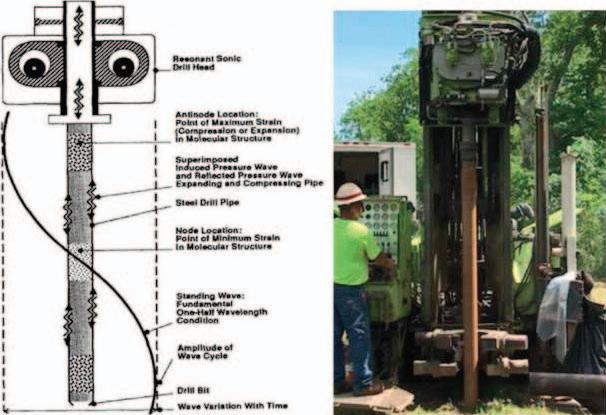
5.Theuseofsonicdrillingorhollowstemaugers shouldbeconsideredtoavoidtheriskofdrilling withfluids.
6.Iffluidsareused,onlygravitypressureshouldbe used,ifpossible.
7.Ifpressurizedfluidsmustbeused,thenahydraulic fractureanalysismustbeperformedtodetermine theestimatedfracturepressure,estimatedfluid pressurefromdrillingactivity,andestimatedfactor ofsafety.
8.Pressuresshouldbemonitoredandkeptbelowthresholdsusinganappropriatefactorof safety.
9.Ifpossible,apressurereliefvalveshouldbeused toprotectagainstspikesinpressurecausedbydrill fluidreturnclogging.
REFERENCES
Alfaro,M.C.andWong,C.K.,2001,Laboratorystudiesoffracturingoflow-permeabilitysoils: CanadianGeotechnicalJournal,Vol.38,pp.303–315.
Andersen,K.H.;Rawlings,C.G.;Lunne,T.A.;andBy,T.H., 1994,Estimationofhydraulicfracturepressureinclay: CanadianGeotechnicalJournal,Vol.31,pp.817–828.
Benoit,J.,1995,Advancesinpressuremetertechnologywithspecificreferencetoclays.InBallivy,G.(Editor), ThePressuremeterandItsNewAvenues,Proceedingsofthe4thInternational Symposium, 17–19May1995,Sherbrooke,Québec,Canada: CRCPress,BocaRaton,FL,pp.125–139.
Bjerrum,L.;Nash,J.K.;Kennard,R.M.;andGibson, R.E.,1972,Hydraulicfracturinginfieldpermeabilitytesting: Geotechnique,Vol.22,pp.319–332.
Bozozuk,M.,1974,Minorprincipalstressmeasurementsinmarineclaywithhydraulicfracturetests.In Proceedings:EngineeringFoundationConferenceonSubsurfaceExploration forUndergroundExcavationandHeavyConstruction,Henniker,NH:AmericanSocietyofCivilEngineers,NewYork, pp.333–349.
Calcagno,F.,Jr.,1983,HydraulicfracturestudyoftheTiber spillwaycofferdam: AEGNewsletter,Vol.26,pp.25–26.
Casagrande,A.andCovarrubias,S.W.,1970, CrackingofEarth andRockfillDams,TensionZonesinEmbankmentsCausedby ConduitsandCutoffWalls:U.S.ArmyEngineerWaterways ExperimentStationContractReportS-70-7.
Chen,Yu-JiongandZhang,Shu-Lu,1989,Testembankmentof fracturegrouting: JournalofGeotechnicalEngineering,Vol. 115,No.11,pp.1668–1672.
Davidson,R.R.;Levallois,J.;andGraybeal,K.,1992,SeepagecutoffwallforMudMountainDam.In ASTMSTP 1129—SlurryWalls:Design,Construction,andQualityControl: AmericanSocietyforTestingandMaterials,Philadelphia,PA,pp.309–333.
Erwin,E.D.andGlenn,J.M.,1992, ASTMSTP1129—Plastic ConcreteSlurryWallforWisterDam,SlurryWalls:Design ConstructionandQualityControl:AmericanSocietyforTestingandMaterials,Philadelphia,PA.
Hamouche,K.K.;Leroueil,S.;Roy,M.;andLutenegger,A.J., 1995, Insitu evaluationof k0 ineasternCanadaclays: CanadianGeotechnicalJournal,Vol.32,pp.677–688.
IndependentPaneltoReviewCauseofTetonDamFailure, 1976,FailureofTetonDam:ReporttotheU.S.Departmentof InteriorandStateofIdaho,U.S.GovernmentPrintingOffice, Washington,D.C.
Ivanov,D.;Horvath,D.;andHeenan,D.,2017,Advancesin measuringgroutingpressuresusinganinstrumentedpacker. InByle,J.,Johnson,L.,Bruce,D.,ElMohtar,C.,Gazzarrini, P.,andRichards,T.(Editors), Grouting2017:AmericanSocietyofCivilEngineers,Honolulu,HI,pp.313–322.
Jaky,J.,1944,ThecoefficientofEarthpressureatrest: Journalof theSocietyofHungarianArchitectsandEngineers,Vol.25,pp. 355–358.
Lo,K.Y.andKaniaru,K.,1990,Hydraulicfractureinearth androck-filldams: CanadianGeotechnicalJournal,Vol.27, pp.496–506.
Luger,H.J.andHergarden,A.M.,1988,Directionaldrilling insoftsoil:Influenceofmudpressures.In Proceedings:NoDigConference: InternationalSocietyofTrenchlessTechnology,WashingtonD.C.
McCook,D.K.andGrotrian,K.O.,2010,UsingSIGMA/W topredicthydraulicfractureinanearthenembankment.In Proceedings:DamSafety: AssociationofDamSafetyOfficials, SeattleWashington,pp.247–271.
Mori,A.andTamura,M.,1987,Hydrofracturingpressure ofcohesivesoils: SoilsandFoundations,Vol.27,No.1, pp.14–22.
Schmertmann,J.H.,1985,Measureanduseofthe insitu lateral stress.In ThePracticeofFoundationEngineer,OsterbergVol. DepartmentofCivilEngineering,NorthwesternUniversity, Evanston,IL,pp.189-213.
Seed,H.B.andDuncan,J.M.,1981,TheTetonDam—Aretrospectivereview.In ProceedingsoftheTenthInternationalConferenceonSoilMechanicsandFoundationEngineering,Vol.3: Stockholm,Sweden,pp.219–238.
Sherard,J.L.,1970,Lossofwaterinboreholesinimperviousembankmentsections.In Proceedingsofthe10th ICOLDCongress,Vol.VI:Montreal,Quebec,Canada, pp.377–381.
Sherard,J.L.,1973,Embankmentdamcracking.InPoulos,S. andHirschfeld,R.(Editors), EmbankmentDamEngineering: JohnWileyandSons,NewYork,pp.272–353.
Sherard,J.L.,1986,Hydraulicfracturinginembankmentdams: ASCEJournalofGeotechnicalEngineering,Vol.112,No.10, pp.905–927.
Sherard,J.L.;Decker,R.S.;andRyker,N.L.,1972,Hydraulic fracturinginlowdamsofdispersiveclay.In Proceedingsof
Environmental&EngineeringGeoscience,Vol.XXIX,No.1,February2023,pp.3–16 15
Schaefer
theSpecialtyConferenceonPerformanceofEarthandEarthSupportedStructures,Vol.1,PartI:AmericanSocietyofCivil Engineers,NewYork,pp.563–590.
USACE(U.S.ArmyCorpsofEngineers),1998, Installationof PipelinesBeneathLeveesUsingHorizontalDirectionalDrilling: U.S.ArmyCorpsofEngineersTechnicalReportCPAR-GL98-1.
USACE(U.S.ArmyCorpsofEngineers),2014, ER1110-11807—DrillinginEarthEmbankmentDamsandLevees:U.S. ArmyCorpsofEngineers,Washington,D.C.
USACE(U.S.ArmyCorpsofEngineers),2020, EM1110-22902—Conduits,Pipes,andCulvertsAssociatedwithDamsand LeveeSystems:U.S.ArmyCorpsofEngineers,Washington, D.C.
Vesic,A.S.,1972,Expansionofcavitiesininfinitesoilmass: ASCE JournaloftheSoilMechanicsandFoundationsDivision,Vol. 98,pp.265–290.
Yanagisawa,E.andPanah,A.K.,1994,Twodimensionalstudy ofhydraulicfracturingcriteriaincohesivesoils: Soilsand Foundations,Vol.34,No.1,pp.1–9.
16 Environmental&EngineeringGeoscience,Vol.XXIX,No.1,February2023,pp.3–16
BestPracticesforPlanningandImplementingSite InvestigationsatFederallyOwnedorRegulatedDams andLevees
KATHLEENBENSKO
FederalEnergyRegulatoryCommission,OfficeofEnergyProjects,DivisionofDam SafetyandInspections,888FirstStreet,N.E.,Washington,DC20426
BRYANK.SIMPSON
U.S.BureauofReclamation,GeotechnicalServicesDivision,EngineeringGeologyand Geophysics,DenverFederalCenter,POBox25007(86-68320),Denver,CO 80225-0007


THOMASA.TERRY
U.S.ArmyCorpsofEngineers,RiskManagementCenter,12596W.BayaudAvenue, Suite400,Lakewood,CO80228
SCOTTR.WALKER*
TennesseeValleyAuthority,DamSafetyGovernance&Oversight,1101MarketStreet, LP1F-C,Chattanooga,TN37402
KeyTerms: DamSafety,LeveeSafety,Geotechnical SiteInvestigations,DrillingProgramPlans,Drilling Guidance,FederalAgency
ABSTRACT
Management,regulation,andreviewoftheplanning andexecutionofintrusivesiteinvestigationsvarywithin eachoffourfederalorganizationsinvolvedwithdam andleveesafetybaseduponvariousrolesandresponsibilities.TheU.S.BureauofReclamation(USBR),the TennesseeValleyAuthority,andtheU.S.ArmyCorps ofEngineers(USACE)areowner-operatorsofdams thatservemultiplepurposes,includingfloodcontrol,hydropower,watersupply,andnavigation.TheFederalEnergyRegulatoryCommission(FERC)regulatesandinspectsnon-federalhydropowerdams,anddevelopsand implementspolicies,programs,andstandardstoensure thesafetyoftheselicensedprojects.Eachorganization (exceptFERC)isalsoresponsibleforoversight,rehabilitation,andrepairofstructuresincludingdamaged levees,canals,anddams,includingsome(inthecaseof USBRandUSACE)thatareoperatedandmaintained byothers.Thispaperprovidesabriefoverviewofthe variousregulationsandguidancerelatedtotheplanning andexecutionofintrusivesiteinvestigationsconducted atstructureswithineachorganization’sportfolio.Italso
*Correspondingauthoremail:srwalker3@tva.gov
providesaprogrammaticoverviewoftheprocessesutilizedbythedifferentfederalorganizationsforplanning, reviewing,andimplementingintrusiveinvestigations.It coversspecificrequirements(guidanceandregulations), timeframesthatareinvolvedwiththereviewprocess, anddiscussesupdatesandchangesthatareplannedor beingconsidered.
OVERVIEW
Thepurposeofthepaperistoexplainhowthefour majorfederalorganizationswithdamandleveesafety programs—theU.S.BureauofReclamation(USBR), U.S.ArmyCorpsofEngineers(USACE),Tennessee ValleyAuthority(TVA),andFederalEnergyRegulatoryCommission(FERC)—planandimplement intrusivesiteinvestigationsforhydraulicstructures. Eachorganizationhasdifferentprimarypurposesand rolesrelatedtodamsandleveeswhichaffectwhyand howsiteinvestigationsforeachareperformedand implemented.
Topicsdiscussedincludethefollowing:
Asummaryofeachorganization’srolesandresponsibilitiesrelatedtodamandleveesafety,including thepurposesoftheirdamsandlevees,regulatory position,emergencyandpost-emergencyworkfor others,andworkforotheroutsideentitiesrelatedto damandleveesafety
Environmental&EngineeringGeoscience,Vol.XXIX,No.1,February2023,pp.17–39 17
Adescriptionofthebasicsiteinvestigationprocessestheorganizationsallfollowandhowriskassessmentsareutilizedininvestigationplanning Abriefdescriptionofhoweachorganizationplans andexecutesintrusivesiteinvestigations,including adiscussionofthevariousregulationsandguidance documentseachorganizationfollows Contracting,communications,levelofinvolvement, andoversightoftheintrusivesiteinvestigation process
DiscussiongenerallyfollowstheorderofUSBR, USACE,TVA,andFERC.Thisreflectsaprogression fromfewertomoreentitiesinvolved,andfromanalmostfullyinternalprogram(USBR)toamixedinternal/externalprogram(USACE)toowneroversightof theprocess(TVA)toregulatoroftheprocess(FERC).
Notalldamandleveesafety-relatedaspectsthatare importanttositeinvestigationprogramsarediscussed. Additionalrequirementscouldincludepreparedsubmittalssuchashealthandsafetyplans(HASPs), qualityassuranceandqualitycontrol(QA/QC)processes,TemporaryConstructionEmergencyAction Plans(TCEAPs),siteaccess,realestateissues,utility clearances,tribalconsultations,NationalEnvironmentalPolicyAct(NEPA)and/orStateHistoricPreservationOffice(SHPO)reviewsorrestrictions,andother archeological,biological,orhistoricalevaluations.
BACKGROUNDONORGANIZATIONS
USBR
Establishedin1902,theUSBR(alsoreferredtoas Reclamation)isbestknownforthedams,powerplants, andcanalsitconstructedinthe17westernstates(see Figure1).Thesewaterprojectsledtohomesteading andpromotedtheeconomicdevelopmentoftheWest. Reclamationhasconstructedmorethan600damsand reservoirsincludingHooverDamontheColorado RiverandGrandCouleeDamontheColumbiaRiver.
Reclamationisalsothesecondlargestproducerof hydroelectricpowerintheUnitedStates.USBR’s53 powerplantsannuallyprovidemorethan40billion kilowatthours,generatenearly$1billioninpowerrevenue,andproduceenoughelectricitytoserve3.5millionhomes.Today,theUSBRisacontemporarywatermanagementagencywithastrategicplanoutlining numerousprograms,initiatives,andactivitiestohelp thewesternstates,NativeAmericantribes,andothers balanceamultitudeofcompetingusesforwater.The missionistoassistinmeetingtheincreasingwaterdemandsofthesestatesandentitieswhileprotectingthe environmentandthepublic’sinvestmentinReclamation’sinfrastructure.
Reclamationplacesgreatemphasisonfulfillingwaterdeliveryobligations,waterconservation,waterrecyclingandreuse,anddevelopingpartnershipswith customers,states,andNativeAmericantribes,and findingwaystobringtogetherthevarietyofintereststoaddresscompetingneedsforlimitedwater resources.
USACE
In1853,USACEbeganworkontheWashington Aqueduct,whichsupplieswatertotheDistrictof Columbia(WarDept,1939)andisstilloperatedby USACE.Subsequently,USACEbecameinvolvedin floodcontrolandnavigationalongtheMississippi Riverin1879withthecreationoftheMississippi RiverCommission(StatutesatLarge,1881).In1885 USACEcompletedthreereservoirsinMinnesotanear theheadwatersoftheMississippiRiverforflood controlandnavigationpurposes(USACE,1885and 2020a).TheRansdell–HumphreysFloodControlAct of1917(StatutesatLarge,1917)wasthefirstfederal FloodControlActpassedbyCongress,andthenthe FloodControlActof1936(StatutesatLarge,1936a) madefloodcontrolafederalpolicyandofficiallyrecognizedUSACEasthemajorfederalfloodcontrol agencywithofficesandprojectsacrossthecountryand overseasterritories(Figure2).
USACEself-regulatesitsdamsandleveesandinspectsandpartiallyregulatesothersunderaprogram authorizedbyPublicLaw(PL)84-99(Statutesat Large,1955andU.S.C.,2020c).USACEisthelargest producerofhydropowerintheU.S.asmeasuredby hydroelectricgenerationcapacityinmegawatts.Additionally,USACEprovidesfloodfightingassistance andaidstheFederalEmergencyManagementAgency (FEMA)indisasterrecoveryefforts.USACEmanagestheNationalInventoryofDamsandtheNational LeveeDatabaseandisworkingwithFEMAonthe NationalLeveeSafetyProgram.
TVA
TVAisacorporateagencyandinstrumentalityof theUnitedStates,createdonMay18,1933,when CongresspassedtheTennesseeValleyAuthorityAct of1933(TVAAct;StatutesatLarge,1934andU.S.C., 2020b)inresponsetoPresidentFranklinDelanoRoosevelt’svisionfor,“acorporationclothedwiththe powerofgovernmentbutpossessedoftheflexibilityandinitiativeofaprivateenterprise”(Roosevelt, 1938).Incontrasttoauthorizationsforotherfederal agencies,theTVAActreferstoTVAas“theCorporation”anddescribesitspurposesasimprovingnavigabilityandprovidingfloodcontrolontheTennessee
Bensko,Simpson,Terry,andWalker
18 Environmental&EngineeringGeoscience,Vol.XXIX,No.1,February2023,pp.17–39
River,initiatingenvironmentalimprovements(reforestationandimprovingfarmingpractices),stimulatingeconomicdevelopmentwithintheTennesseeValley,andprovidingfornationaldefense.

Asthenation’slargestpublicpowerproducer,TVA utilizesmultiplegenerationsources,includingnuclear, naturalgas,coal,andrenewables.Hydroelectricrepresentsabout10percentofTVA’soverallgenerationmix, andtwenty-nineofTVA’sriverdamprojects(along withtheRaccoonMountainPumped-Storagefacility) generateelectricity.TVAceasedreceivingfederalappropriationsin1999andmadeitsfinalscheduledrepaymentonCongress’original$1billioninvestmentin theTVApowersystemin2014.TodayTVAisfullyselffunded,withnearlyallrevenuederivedfrompower sales.WhilethisfiscalmodeldifferentiatesTVAfrom USBRandUSACE,akeysimilarityisthatTVA’sDam SafetyProgram(DSP),likethoseofotherfederaldam owners,isself-regulated.
TVAoperateswithinapowerserviceareathat coverspartsofsevenstates,asshowninFigure3. AllbutoneofTVA’sriverdamsarelocatedwithin thedrainagebasinoftheTennesseeRiver,whichis alsodepictedinFigure3.TVA’scurrentriverdam
inventoryincludes49projectscomprisedof88individualstructures(includingsaddledams,dikes,etc.). TVAconstructed42riverdamprojects(80totalstructures),purchasedsixotherprojects(sevenstructures), andacquiredoneprojectfromUSACEaspartofthe TVAAct.
Inadditiontotheriverdams,TVA’sDSPoversees ninewaterretentionstructuresconstructedtosupport ongoingfossilandnucleargeneration,sixleveesoriginallyconstructedforvectorcontrolandwhichnow providerecreationandwildlifehabitatbenefits,and onehistoricgristmilldamsituatedonlandTVAacquiredaspartofaflowageeasement.Allnon-river damsareclassifiedaslow-hazardpotentialstructures. AseparateregulatoryprogramatTVAprovidesgovernanceandoversightofcoalashandcoalwashfinesimpoundmentsatactiveanddecommissionedfossilgenerationsites.
FERC’soriginbeganwiththepassageoftheFederalWaterPowerActof1920(FWPA;Statutesat Large,1921)whichprovidedthefederalgovernment
BestPracticesforPlanningSiteInvestigationsatDamsandLevees
Figure1.U.S.BureauofReclamationregions.
FERC
Environmental&EngineeringGeoscience,Vol.XXIX,No.1,February2023,pp.17–39 19
withmorecomprehensivecontrolofthenation’snavigablewaterresources.In1935theFWPAbecame PartIoftheFederalPowerAct(U.S.C.,2020a),underwhichtheFederalPowerCommissionevolvedinto anindependentregulatoryagency(McKernan,1950). In1977,asaresultoftheDepartmentofEnergyOrganizationAct(StatutesatLarge,1980),theFederal PowerCommissionwasre-designatedastheFederal EnergyRegulatoryCommission.Sincetheenactment oftheFederalPowerAct,CongresshasassignedexpandedresponsibilitiestoFERCthroughvariouslaws toincludeproposalreviewofinterstatenaturalgas pipelines,storageprojects,liquifiednaturalgasterminals,responsibilitiesrelatingtobulk-powersystemreliabilityandcybersecurity,andlicensesfornon-federal hydropowerprojects.

FERC’soversightofnon-federalhydropowerdevelopmentishandledbythreeofsixdivisionswithin theOfficeofEnergyProjects.TheDivisionofDam
SafetyandInspections(D2SI)executestheCommission’sDamSafetyandPublicSafetyProgramsbyimplementingpolicies,programs,andstandardsfordam safetytoensurethatjurisdictionalprojectsareinspectedandevaluatedintheirdesign,construction, operation,maintenance,andsecurityphasestoprotectlife,health,property,andtheenvironment.Project compliancetothetermsandconditionsofthelicensesandexemptionsregardingdamsafetyarealso assessed.D2SI’soversightroleisexplainedintheCode ofFederalRegulations(CFR;CFR,2020).D2SIis comprisedoffiveregionalofficesasshowninFigure4, andaHeadquartersofficeinWashington,D.C.,totalingabout130personnel.
FERCregulatesover2,500hydropower-producing projectswithintheUnitedStates.Federallyowned hydropower-producingprojectsdonotfallwithin FERC’sjurisdiction;however,FERCdoesregulate privatelydevelopedhydropowerfacilitieslocatedat
Bensko,Simpson,Terry,andWalker
Figure2.UnitedStatesArmyCorpsofEngineersdistrictsandheadquarterslocations.
20 Environmental&EngineeringGeoscience,Vol.XXIX,No.1,February2023,pp.17–39
USACE-andUSBR-ownedprojects.(Therearecurrentlynoprivatelydevelopedhydropowerprojectsat TVAfacilities.)TheprojectswithinFERC’spurview varygreatlyintype,size,design,age,purpose,andoperation.Thenumberoflicensedprojectsandlicensees resultsinaratherdynamicportfoliobecauseitfrequentlychangesasnewprojectsarelicensedandother licensesaresurrendered.Figure5showsthedistributionofbothFERC-regulatedandfederalhydropower projects.
Figures6through8summarize(asapplicable),the inventory,structurepurposes,roles,anddegreeto whichdamorleveesafetyriskisappliedtoeach organization’soveralldamsafetyprogramandintrusivesiteinvestigations.Thenumberofregulated structuresforUSBRandUSACEreferstoadditionalfacilitiestheyregulate.Emptycellsindicate not applicable.Collectively,thesefiguresprovideasummaryofthesimilaritiesanddifferencesbetweeneach organization.
Asummaryoftheorganizationalrolesshownin Figure8isasfollows:
Self-governing–organizationregulatesitsownactionsrelatedtodamorleveesafety.
Regulator–regulatesallaspectsofdamorlevee safety.TheFERCregulatoryroleislimitedtothose structuresthatarepartofnon-federalhydropowerproducingfacilities(however,thefacilitiesmaybe locatedatfederalprojects).Pertinentstructuresrelatingtothesefacilitiesareincluded,suchassaddledams,etc.USACE’sregulatoryroleislimitedto leveesthatwerebuiltbyUSACEandturnedover toalocalsponsortooperateandmaintain,structuresforwhichanentityhaselectedtoparticipate inthePL84-99program(whichprovidesreimbursementforspecificdamagestoleveesthatresultfrom high-waterevents),andreviewofrequestsbynonUSACEentitiesforpermitstomodify,alter,oroccupyanyexistingUSACE-constructedpublicworks projectorassociatedlandsthatwouldotherwise beprohibitedby33U.S.C.§408(U.S.C.,2020d). (ThisstatuteiscommonlyreferredtoasSection 408,andtheassociatedauthorizationsareknownas 408permits.)

BestPracticesforPlanningSiteInvestigationsatDamsandLevees
Figure3.LocationsofTennesseeValleyAuthority(TVA)riverdamswithintheTennesseeRiverwatershed(lightershading)andTVApower servicearea(darkershading).
Environmental&EngineeringGeoscience,Vol.XXIX,No.1,February2023,pp.17–39 21
Emergencyassistance–aidsduringfloodemergenciestolocalsponsorsuponrequest.
Repairandrehabilitation–forstructuresthatare partofthePL84-99programsrelatedtoleveesand limiteddamsthatwerebuiltbyUSACEandarenow operatedandmaintainedbyalocalsponsor.USACEalsoactsasFEMA’sengineeringandcontractingbranchwhenrespondingtonationallydeclared disasterssuchashurricanesandfloods.

USBR,USACE,TVA,andFERCaretransitioningtowardfullyrisk-informedmanagementoftheir respectivedamandleveesafetyprograms.However, internaldesignandguidancestandards,externalregulations,treatyobligations,andcontractsdocontinue tocontrolsomeaspectsoftheprograms(tovarying degrees)andsiteinvestigationsisoneareawhereriskinformedprocesseshavebeenslowertoimplement.
USBRisthefurthestalongintheprocess,withthe majorityofitsdecision-making,design,andsiteinvestigationsinformedbyrisk.TVAandFERCaretransitioningtorisk-informedprocessesformanagementof theirfacilities,includingsiteinvestigations,butboth alsohavestandards-basedcriteriaandrequirements thatmustbefollowed.
USACEisusingrisktomanagedamandleveeportfoliosandtoinformdesigns;however,forsiteinvestigations,integrationofriskvariesbetweenthedam andleveeprograms.USACEtypicallyavoidsdrilling inorneardams(particularlyearthembankments)exceptinsupportofdesigns,aspartofissueevaluation studies(IESs)followingriskassessments,ortorepair orreplaceinstrumentationorreliefwells.Leveesfully ownedandoperatedbyUSACEaregenerallytreated similarlytothedamswhenitcomestointernalinitiationofsubsurfaceinvestigationprograms.However, unlikedamsthatoccupycomparativelysmallfootprints,leveesarelongstructuresthatoftenparallelmajorriversformanymiles.Thisgeometryandgeography commonlyplacetheminconflictwithtransportation andutilitycorridorsandmakethemattractiveaslocationsforparksorsimilaropenspace.Entitiesexternal toUSACEthatwishtoplacestructuresin,on,orunderUSACE-ownedleveesutilizetheSection408permitprocess(whichdoesnothaveariskcomponent)to requestpermissiontoconductsubsurfaceinvestigation insupportoftheirneeds(e.g.,designofbridges,directionalboresforpipelines,utilitytowers,picnicsheltersandoutbuildings).TheSection408processalso appliestodrillinginleveesthatareownedandoper-
Bensko,Simpson,Terry,andWalker
Figure4.FederalEnergyRegulatoryCommissionregionalofficesandcoverageareas.
22 Environmental&EngineeringGeoscience,Vol.XXIX,No.1,February2023,pp.17–39
JOINTOPERATIONSBETWEENTHE ORGANIZATIONS USBRandUSACE

USBRandUSACEjointlyoperateseveralfacilities, withtheUSBRtypicallymakingday-to-dayoperationaldecisionsrelatedtowaterandhydropower,while USACEtypicallymakesdecisionsrelatedtofloodcontrol.Theentitythatcontrolsthemainoperationisconsideredtheleadorganizationanddetermineswhich ofthetwowillleadindamsafetypractices.ExamplesoftheseincludetheFolsomDamjointuseproject andtheGarrisonDamproject’sSnakeCreekEmbankment,whichseparatesLakeAudubon(whichis controlledbyUSBRforirrigationwatersupply)from LakeSakakawea(whichiscontrolledbyUSACEprimarilyforfloodcontrol).
TVAandUSACE
TVA’sportfolioincludes10damswithnavigation facilities—nineontheTennesseeRiverandoneon theClinchRiver.Ateachfacility,TVAownstheinfrastructureandisresponsibleformaintenanceofthe dam,whileUSACEisresponsibleforoperationand maintenanceofthenavigationlocks.TVAmanages reservoirlevelsanddischargesacrossthesystemto supportnavigation.USACEdesignedandisnowcontractingforandmanagingconstructionofnewnavigationlocksattheKentuckyandChickamaugaprojects becauseUSACEcanreceivethefederalappropriations necessarytofundtheprojects.Additionally,thenorthernendoftheTennessee–TombigbeeWaterway(which isoperatedandmaintainedbyUSACE)is8.5miles upstreamfromTVA’sPickwickLandingDam.WaterfromPickwickLakeisreleasedwhenvesselslock throughJamieWhittenLockandDaminMississippi.
TVAalsocoordinatescloselywiththeUSACEdistrictofficesinNashvilleandCincinnatiforroutineand floodoperationsontheTennesseeandCumberland
BestPracticesforPlanningSiteInvestigationsatDamsandLevees
Figure5.FederalEnergyRegulatoryCommission(FERC)-regulatedandfederallyownedhydropowerprojects(FERC,2017).
atedbyasponsor(forwhichUSACEonlyservesa regulator).
Environmental&EngineeringGeoscience,Vol.XXIX,No.1,February2023,pp.17–39 23
Bensko,Simpson,Terry,andWalker
Rivers.Thelowermostreservoirsoneachriver(KentuckyLakeandLakeBarkley,respectively)arehydraulicallyconnectedbyanavigationcanal.TVA runsthehydraulicmodelforthecombinedsystem andschedulesnormaloperationdischargesfromboth dams.TVAalsoscheduleshydroelectricgeneration fromtheotherUSACEdamsupstreamontheCumberlandandprovidesUSACEwithdischargesfrom
GreatFallsDam(whichistheonlyTVAriverdam intheCumberlandwatershed).Duringfloodevents ontheOhioRiver,USACEschedulesdischargefrom KentuckyandBarkleyDamstoreduceimpactstothe lowerOhioandMississippiRivers.Inaddition,TVA utilizesUSACEcadrestoassistwithroutinesemiquantitativeriskassessments(SQRAs)forselected dams.

 Figure6.Summaryofstructureinventories.
24 Environmental&EngineeringGeoscience,Vol.XXIX,No.1,February2023,pp.17–39
Figure7.Primaryandsecondarypurposesofdamsandlevees.
TVAandUSBR
Althoughtherearenocurrentjointoperations,TVA andUSBRcollaboratedcloselyintheyearsimmediatelyfollowingpassageoftheTVAAct.Becauseit tooktimetocreateadesignbranch,TVAhiredUSBR todevelopthedesignsforNorrisandWheelerDams (whichiswhyNorrisistheonlyTVAdamwithdrum gates).TVAiscurrentlyworkingwithUSBRonrehabilitationofringsealgatesatHiwasseeDam,thedesignforwhichisvirtuallyidenticaltothoseatGrand CouleeDam.
FERCandUSBR,USACE,orTVA

TherearenumerousprojectswhereUSACEor USBRisthedamownerandoperatorwitha third-partyhydropowerproviderthatisregulated byFERC.ForUSACEstructures,thehydropower providergenerallycontrolstheday-to-dayoutflow operationsincoordinationwithUSACE,whileUSACEcontrolsthefloodpoolandfloodcontrol operations.Iftheprojectsalsohavenavigation, thenUSACEcontrolsthenavigationthroughthe locksandthenavigation-relatedpools;examples

BestPracticesforPlanningSiteInvestigationsatDamsandLevees
Figure8.Summaryoforganizationrole(s).
Environmental&EngineeringGeoscience,Vol.XXIX,No.1,February2023,pp.17–39 25
Figure9.SimplifiedTennesseeValleyAuthorityDamSafetyProgramorganizationalchart.
oftheseincludemanydamsalongtheColumbia River.
ForReclamationassets,thirdpartiesarepermittedunderaleaseofpowerprivilege(LOPP)contract.LOPPprojectsmustnotimpairtheefficiency ofReclamation-generatedpowerorwaterdeliveries, jeopardizepublicsafety,ornegativelyaffectanyother Reclamationprojectpurpose.
TVAcoordinateswithFERClicenseesthatoperate damswithintheTennesseeRiverwatershed(mostnotablyontheLittleTennesseeRiverdownstreamfrom FontanaDam),buttherearenoformaljointoperationsbetweenFERC,theirlicensees,andTVA.
GENERALCONSIDERATIONS, REGULATIONS,ANDGUIDELINES
ThepartiesinvolvedandthereasonsforconductingintrusiveinvestigationsatstructuresownedorregulatedbyUSBR,USACE,TVA,orFERCvary.For structuresownedbyoneoftheorganizations,theprocessmaybeself-initiated(suchastocollectinformationtobetterquantifyanidentifiedpotentialfailure mode(PFM),ortosupportdesignofamodification), orinitiatedbyanoutsideorganization(e.g.,transportationdepartments,pipelineowners,orthird-party hydropowerdevelopers).Forstructuresregulatedby USBRorUSACE,theprocessistypicallyinitiatedby anoutsideorganization;inadditiontotheexamples above,thesemayalsoincludealocalfloodcontrolor irrigationdistrict.ForFERC-regulatedstructures,the processisalwaysinitiatedbythelicensee.
Eachfederalorganizationutilizesregulationsand guidelinesthatdescribepermissibleorpreferredinvestigationtechniques,minimumqualifications,andsubmittalrequirements.Whilethespecificsofthevarious documentsdiffer,theunderlyingfundamentalprincipleis DONOHARM tothestructure.Theprimary governingdocumentsforeachorganizationareas follows:
USBR: GuidelinesforDrillingandSamplinginEmbankmentDams (USBRDrillingGuidelines;USBR, 2014)
USACE: DrillinginEarthEmbankmentsandLevees (ER1110-1-1807;USACE,2014a)
FERC: GuidelinesforDrillinginandNearEmbankmentDamsandtheirFoundations,Version3.1 (FERCDrillingGuidelines;FERC,2016)
TVA: EvaluationsandDesignofDams (TVAStandardProgramsandProcesses(SPP)-27.001; TVA,2022a),whichreferencestheFERCDrilling Guidelines
Supportingdocumentsthatmaybeusedtoassist withtheplanningofintrusiveinvestigations,including
internalandexternalguidancefordrillingandabandonmentofborings,andmethodologies,arelisted inthe References section.TheseincludeAustralian DrillingIndustryAssociation[ADIA],2020;ASTM, 2014,2016,2017,2018a–e;Dustmanetal.,1992;Farrar,1999;FEMA,2005;Luteneggeretal.,1995;Ruda andBosschler,2005;TVA,2013;USBR,1990,1998a, 1998b,2001;USBRandUSACE,2019;andUSACE, 2020b.
Whiletheintentofthisarticleisnottoreiterateinformationpublishedinthesedocuments,thefollowing areconsiderationsthatconstitutegoodpracticeand aregenerallyapplicabletointrusiveinvestigationplanningforprojectsatanydamorlevee(whetherforor regulatedbyafederalorganizationornot).
ResearchingAvailableBackgroundInformation
Researchistheleastinvasiveandsafestwayto gatherinformation.Thistaskincludesgathering,organizing,andreviewingallavailableinformationabout thestructureandsubsurfaceconditions.Potential sourceswillvaryfromprojecttoprojectbutshould includeallrecordsheldbytheownerandpriorownersattheiroffices(local,regional,andnational),at thesite,historicarchives(newspaper,county,state, andfederal–includingtheNationalArchivesand RecordsAdministration),stateandfederalagencies (e.g.,UnitedStatesGeologicalSurvey;stategeologicalsurveys;UnitedStatesDepartmentofAgriculture, NaturalResourcesConservationServicesoilsurveys), andotherresourcesasneeded.
Itisessentialtounderstandthefollowinginformationataminimumaspartofthepreparationforarisk assessmentandanysiteinvestigation:
Originaldesignplansandspecificationsforthe structure
As-builtdocumentation,andhistoryofmodifications
Recordphotosfrompreconstruction,duringconstruction,andpost-construction
Relevantanalyses(particularlystabilityandseepage)
Bedrockgeology,includinginformationaboutgeologicstructure,seismotectonicfeatures,joints,or discontinuities
Surficialgeologyincludingthegeomorphologyof thesiteandsurroundingarea
Hydrogeologicconditions
Inspectionrecords,includinginstrumentationreadings,recordsandperformanceevaluations
Muchofthisinformationistypicallycontained inthesupportingsummarydocumentationforeach structure;however,forvariousreasonsthisisnot
Bensko,Simpson,Terry,andWalker
26 Environmental&EngineeringGeoscience,Vol.XXIX,No.1,February2023,pp.17–39
Table1. Supportingsummarydocumentnomenclatureby organization.
Organization
SupportingSummaryDocumentName andAcronym
USBRComprehensiveReview(CR)
USACEPeriodicAssessment(PA)orRiskAssessment (RA)
TVASupportingTechnicalInformation(STI)
FERCSupportingTechnicalInformationDocument (STID)
USBR = U.S.BureauofReclamation;USACE = U.S.ArmyCorps ofEngineers;TVA = TennesseeValleyAuthority;FERC = Federal EnergyRegulatoryCommission.
alwaysthecaseinpractice.Eachorganizationusesdifferenttermsforthesupportingsummarydocuments; seeTable1fortheorganization-specificnomenclature.
PlanningSiteInvestigations
Intrusiveinvestigationprogramsshouldbedesigned bygeotechnicalandgeologicalprofessionalswithexperienceindamandleveesafety.Thefirststepisto definethequestionstobeansweredaswellasthegoals andtargetsoftheprogram,whichwillinformthelocationsanddepthsfortheexplorations,thesamples andotherinformationtocollect,andtheinstrumentationtoinstall.Inmanycases,intrusiveinvestigationprogramsareinitiatedfollowingriskassessments. ForPFMswithadispositionof“InsufficientInformation,”drillingorexcavationmaybenecessaryto collecttheinformationrequiredtoproperlyevaluate thePFM.ForSQRAsorquantitativeriskassessments (QRAs),informationfromtheinvestigationsmaybe neededtoreduceuncertaintyrelatedtorisk-driving failuremodesidentifiedbytheSQRAortoinformor refinenodalestimatesinaQRA.
Theneedfortheinformation,however,mustbebalancedagainsttheriskassociatedwithcollectingit.To thatend,theplanningteamshouldidentifywhatinformationcanbeobtainedbynon-invasiveandminimally invasivemethods.Additionally,forsomeinvestigation programs,phasingmaybeappropriate,withtheprogramtoendwhensufficientinformationisavailable toanswerthequestionsposed,thegoalshavebeen achieved,ortheriskofcontinuingtheprogrambecomesunacceptable.
Documentation
USBR,USACE,TVA,andFERCallrequire detailedplansforfieldinvestigationswithsimilarcontent,althoughnomenclatureandspecificsof howinformationispresenteddifferbyorganization.
FollowingFERC’smethodfororganizinginformation, intrusiveinvestigationplansshouldgenerallyinclude:
(1)Purpose,objective,andjustificationforthework, includinganswerstothefollowing:
• Whydoyouwanttodrillordiginthedamor levee(i.e.,putadefectinthestructure)?
• Didyouconsiderotheralternatives?
• Howwilltheinformationhelpyoumakeadecision?
• Whatifyoudidnothavetheinformation? Wouldthedecisionchange?
(2)Existinginformationcollectedduringtheresearchphaseshouldbesummarizedandkeyinformationpresented,includingbutnotlimitedto thefollowing:
• Geologic,hydrogeologic,andgeotechnicalinformation
• Boringlogsandothersubsurfaceexplorations
• As-builtdrawingsandspecifications;record photographsoforiginalconstructionandmodifications
• Relevantdesignandconstructionreports
• Relevantanalyses
• Inspectionandassessmentreports
• Instrumentationplans,installationrecords, data,andperformancereports
(3)Essentialgeologicandengineeringdrawings shouldshowthefollowingitems:
• Embankmentzones
• Detailsofsubsurfacematerialclassification, geologiccontacts,andcontinuityinterpretationssupportedbyallnearbydrillingandsamplingdetails
• Depthtothetopofrockandallotherzonesof importance
• Piezometerlocationsshowingscreenedinfluencezonesandrecordedpiezometriclevelstied tothereservoirwaterlevel
• Otherinstrumentationsuchasinclinometers, movementmonuments,etc.,showninthecontextofthefoundationgeologycontactsandinterpretations
• StandardPenetrationTest(SPT)blowcounts orother insitu andlaboratorytestresultsdefiningengineeringproperties
• Geophysicaldata,whereuseful(e.g.,crosshole shearwavevelocityprofiles)
• Estimatedextentofanyzonesofinterest,both naturalandmade-made(e.g.,groutholes)
• Seepageareastiedtoembankmentzonesand geologicunits,wherepossible
• Locationsofallinternalandexternalstructures,includingseepagecontrolfeatures,conduits,etc.
BestPracticesforPlanningSiteInvestigationsatDamsandLevees
Environmental&EngineeringGeoscience,Vol.XXIX,No.1,February2023,pp.17–39 27
• Locationandtypesofanydistressfeatures (seepage,wetspots,sandboils,sinkholes,etc.)
(4)Drillingscopeandmethodology:
• Numberandlocationofproposedborings
• Utilities,surfaceandundergroundobstacles,and accessibility
• Materialsexpectedtobedrilled,sampled,and tested
• Depth,diameter,bearing,andinclinationofborings
• Drilling,sampling(e.g.,SPT,shelbytube,HQ3 wirelinerockcore),and insitu testingmethods (e.g.,vaneshear,pressuremeter,waterpressure [packer]tests,etc.)
• Detailsoftheproposeddrillingequipmentand tooling
• Instrumentationandboreholecompletionrequirements(influencezone,seals,etc.)
• Personnelresponsibleforloggingmaterialsand assuringgeologicdrawingsareupdatedregularly duringthedrillingprogram
• Fieldandlaboratorytestingprogram
• Verificationthat insitu testingpressureswillnot causehydraulicfracturing
(5)Boreholecompletionshouldanswerthefollowing questions:
• Howdoyouplantouseorrepairthedefect?
• Haveyoucheckedthetremiegroutingpressures (hydrostatichead)tomakesuretheywillnot hydraulicallyfracturethestructure?
• Doesgroutingneedtobestagedtocontrolthe pressures?
• Howwillyoubackfillacrossadrainagefeature?
• Istheinstrumentationplanned?
(6)Instrumentationinformation:
• Plannedconstructiondetailsandconstruction methods
• Verificationthatwelldevelopmentandrehabilitationwillnotcausehydraulicfracturingor damagethecasings
• Isinstrumentationtemporaryorpermanent? Willitbeautomated?
(7)Documentationandcoordinationshouldanswer thefollowingquestions:
• Whataretheloggingproceduresorspecifications(e.g.,UnifiedSoilClassificationSystem,InternationalSocietyforRockMechanics, organization-specific)?
• Whatformswillbeused?
• Whatinformationneedstobecollectedinthe fieldduringthedrilling?
• Whoisresponsibleforupdatingtheinformationonthedrawings?
• Howfrequentlywilltheboringlogsbesentin fromthefieldtoupdatethedrawings?
• Whodecidesonchangestotheplanduringthe investigation,andhowarechangesapproved?
(8)Personnelexperienceshouldincludethefollowing:
• Explorationteam:Listmembersoftheexplorationteamthatdevelopedthesiteinvestigationplan.Includename,organization,title, registration,andyearsofexperience
• Drillrigoperators:Includenameandyearsof experience.Noteexperiencedrillinginornear damsorlevees
• Fieldsupervisionpersonnel:Includename,organization,title,registrations,andyearsofexperiencewithdamandleveeinvestigations
(9)Evaluationofpotentialrisks:includeanevaluationoftheriskofhydraulicfracturing,erosion, contaminationofdrainagefeatures,heave,orany otherpotentialdamage.Thisshouldincludethe following:
• Adetaileddescriptionofanydrillingfluiduse includingdetailsonthecirculationsystem,locationswherefluidwillcontactsoil,andcirculationpressuresthatwillbeused
• Monitoringneedsduringdrillingandacontingencyplaniflossofdrillingfluidorothercomplicationsareobservedduringdrilling
• Measurestominimizetheriskofdamagetothe dam,levee,orfoundation
• Measurestopreventthepossibilityofcrosscontaminationandleakagefromconfinedand separategroundwateraquifers
• Measurestopreventdrillcontactwithstructuralfeatures,suchasconduits
• Nearbyinstrumentswhosebehaviorwillbe monitoredduringtheinvestigationandtheexpectedresponse,includingthresholdandlimit values,andcontingencyplansforanunexpectedresponse
• Anemergencyactionplanincludingalistof emergencyequipmentandsuppliestohaveonsite(phoneorradio,filtermaterials,groutmaterials,etc.)
• Potentialremediationproceduresforrisks identified
(10)Other:
• Siteaccessmethods
• Environmentalprotectionmeasures
• NEPA,SHPO,orotherrequirementsandrestrictions
SafetyBeforeScope
Afinalconsiderationisthatinallcases,damand leveesafetyshouldbeprioritizedabovescope.Owners, consultants,anddrillingcontractorshavebeenguilty
Bensko,Simpson,Terry,andWalker
28 Environmental&EngineeringGeoscience,Vol.XXIX,No.1,February2023,pp.17–39
ofpushingtocompleteascopeofworkwhilelosingfocusontheoverallsafetyofthestructure.Ifthe subsurfaceconditionswereknown,therewouldbeno needfortheexplorationprogram.Thus,iftheconditionsencountereddifferunfavorablyfromwhatwasexpected,itbecomescriticaltostopandre-evaluatethe planandtheassociatedrisk.Thisis(inpart)whyminimumexperiencerequirementsexistforpersonnelexecutingtheprograminthefield.
ORGANIZATION-SPECIFICPLANNING AND/ORREVIEWPROCESSES
Thissectionprovidesadditionaldetailsregarding planningand/orreviewofintrusiveinvestigationprograms,specifictoeachorganization.
Oncetheneedforanintrusiveinvestigationprogram isjustified,amultidisciplinaryteamdeterminesexplorationcomponentsrequiredtoadequatelyaddressthe dataneeds.Ideally,theexplorationteamincludesthe principalengineer,principalgeologist,geophysicists, andexpertsinlaboratoryanalysis, insitu testing,and otherdisciplinesasneeded.Dataneedsandinvestigationplansarediscussedtoensurecompatibility.Items todetermineincludethefollowing:
Purposeoftheinvestigation
Costoftheexploration
Requiredsampletypeandsize(disturbedorundisturbed)
Acceptabledrillingandinvestigativemethods
Depth,diameter,andinclinationofdrillingrequired Materialstobedrilledandsampled
Utilities,surfaceandundergroundobstacles,andaccessibility
Developmentoffieldexplorationrequests(FERs) occursinternallywithintheUSBRforavarietyof clients,withthelargestpercentagefromtheUSBR DamSafetyoffice.OtherclientsforFERsincludethe BureauofIndianAffairs,BureauofLandManagement,NationalParkService,stateagencies,andother waterdistrictauthorities.Typically,FERsaredevelopedfortheDamSafetyOfficeattheTechnicalServiceCenter,alongwithotheragencies.FERsforother agenciesoccasionallymaybedevelopedwithinthevariousUSBRregions.
AmajorityofFERsarewrittentobettercharacterizesubsurfaceconditionsinsupportofexisting damsafetyissueevaluations,correctiveactionstudies,orfinaldesignsfordammodifications.Other casesforFERdevelopmentincludeassessmentor feasibility-levelsubsurfacecharacterizationsofnew damsites,retrofittingexistingdamsforhydropower, linearprojectssuchascanalsorpipelines,andmany otherprojectapplications.
FERsarewrittenfollowingtheUSBRDrilling Guidelines(USBR,2014),whichsupersedeUSBR’s 1989policydocument.TheUSBRDrillingGuidelinesprovideagencypolicyfortheinvestigationofembankmentdams,includinginvestigationplanning,site preparation,boreholeadvancement,subsurfacetesting,andboreholecompletion.
Specifically,theUSBRDrillingGuidelinesrequire considerationofwhethertheneedforcollecteddata justifiesthecostandpotentialrisktothestructurecreatedbythedatacollectionprocess.Thisincludesthe determinationofpotentialconsequencesifnoaction istakencomparedwithsubsequentinvestigationcost estimates.Consequencesincludeboththeriskandlikelihoodofworseningconditions,whichcoulddriveup futurecostsofremediationifrequired.
Damfoundationgeometryandhazardoffracturing Instrumentationandcompletionrequirements
Typicaldamsafetyinvestigationsincludesampling andtestingmethodstodeterminethepotentialforliquefaction(dynamicstability),seepageandpiping(includingfiltercompatibility),staticstability,collapse offoundationsoils,andcracking.Emergencyrepairs anddamremediationactivitiestypicallyrequiresome drillingcomponenttocollectneededdata.
Specificconsiderationsrelatedtointrusiveinvestigationsincludethefollowing:
Hydraulicfracturingduringthedrillingprocess and/orboreholecompletioncanopenseepagepaths andcreateconditionsconducivetointernalerosion, piping,andultimatelydamfailure.Locationsorsituationsthatrequireparticularcare(orpreferably avoidance)areasfollows:
◦ Inornearcutofftrenchesorcutoffwallswhere stressconcentrationsand/orhighgradientsare morelikelytoexist
◦ Nearstructuresorconduitswithinembankments
◦ ImperviousZone1corewithaninternalslope ratiosteeperthan0.5horizontalto1vertical (0.5H:1V)
◦ ThinZone1core
◦ UpstreaminclinedZone1core
◦ Nearabutmentswhereabruptchangesinslopes (shoulders)occur
◦ Inareaswheretheembankmentissubjectto transversedifferentialsettlementduetolarge changesinthicknessofcompressiblefoundation soils
◦ Nearabutmentssteeperthan0.5H:1V
BestPracticesforPlanningSiteInvestigationsatDamsandLevees
USBR
Environmental&EngineeringGeoscience,Vol.XXIX,No.1,February2023,pp.17–39 29
◦ Imperviouszonesconsistingofsiltandmixtures offinesandandsilt(e.g.,lowplasticitysoilsthat aremoreeasilyfractured)
◦ Drillinginorthroughgroutcurtains
◦ Nearareassoftenedorweakenedbyseepage
◦ Inlocationsofknowndefectsincompactedfill Damagetointernaldrainagefeatures,eitherdueto drillingorcontaminationwithgroutduringboreholecompletionorabandonment
Drillingorexcavatingatthetoeofadamwherea criticalhydraulicgradientorartesianconditionsexist,includingtheneedtoconstructadrillingberm
Drillingandsamplinglooseorunconsolidatedmaterialsandbalancingdrillingtechniques(e.g.,mud rotary)againstthepotentialforhydrofractureifthe holeisadvancedthroughtheembankment
Presenceofloosecollapsiblesoilswherewetting couldleadtocollapse,cracking,andultimatelyfailureofthestructure.Collapsiblesoilsarepresentin variouslocationsinthearidwesternstatesandunderliesomeearthdamsandsaddledikes.
Qualificationsandexperienceoftheleaddriller whenuseofReclamationcrewsisnotanoption
Preferred,restricted,andprohibiteddrillingtechniques
Instrumentationinstallationsandboreholecompletionorabandonment.Whenusingneatcement grout,specifyingtypeKcement,oraddinguptoone percentgypsumoraluminumpowderwillgivethe cementexpansiveproperties,whichmaybeadvantageousinembankmentdamswhereinternalseepage isanissue.
InadditiontointrusiveinvestigationsconductedundertheFERprocess,drillingassociatedwithremediationcarriesrisksthatmustbeconsidered.Examples includetheuseofcompressedairasadrillingfluidfor advancinggroutholesandjetgroutingwhichinvolves drillingholeswithveryhighairandfluidpressuresat rapidrates.
USACE
USACEsiteinvestigationsfallundermultipleUSACEregulatoryandguidancedocuments(USACE 2001,2014a,2014b,2018,2019,2020,2021)foundin the References section.
TheDrillingProgramPlan(DPP)processdescribed inER1110-1-1807(USACE,2014a)appliestositeinvestigationsatUSACE-ownedandUSACE-regulated damsandlevees,includingsiteinvestigationsconductedunderSection408.Thisincludesanyintrusive workinto,through,orbelowUSACEdamsandlevees withafederalinterest.
ER1110-1-1807includesabackgroundsectionon thepotentialproblemsrelatedtodrillingindamsand leveesandspecificallyidentifiesbasicrisksandpotentialbenefitsofdrillingwithfluidsandtheneedtobalancetheneedforusingfluidswiththepotentialrisks tothestructures.Thedocumentlaysoutthepolicyrequirementsasfollows:
DPPsneedtodiscussoraddressthefollowing topics:
◦ Justificationfortheplannedexploration(s)
◦ Existingdatareview
◦ Restrictionontheuseoffluidsfordrillingindams andlevees
◦ Riskidentificationandmitigation
◦ Boreholecompletion
◦ Drillingpersonnelrequirementsforthedrillerand on-siteoversightbyageologistorengineer
◦ Approval
◦ Exemptionrequirements
AppendixBofER1110-1-1807containsfurther guidanceandageneraloutlineofwhatshouldbeincludedintheDPP.Thesecontentsaresimilartothose describedpreviouslyinthedocumentationsectionand alsoincludethefollowing:
Riskevaluation:thissectionshouldincludeallthe potentialproblemstheproposedinvestigationplan couldcausetothestructureandhowtheyhavebeen addressedbytheplan,includingemergencymeasuresandemergencycontacts
DistrictDamorLeveeSafetyOfficercertification thattheplanfollowsER1110-1-1807
Additionalrequirementsbeyondwhatislistedabove includeaminimumoffiveyearsofexperiencedrilling indamsandleveesforthedrillerandfieldpersonnel loggingtheboringsandtheneedforeitheralicensed engineerorgeologisttobeonsiteandinresponsiblechargeofthedrillingwork.Thispersonneedsto beknowledgeableenoughabouttheplanneddrilling tobeabletorespondtoanysituationsoremergenciesthatmayarise.Lessexperiencedpersonnelare notexcludedfromloggingborings,providedafully experiencedsupervisoryprofessionalispresentonsiteduringdrillingoperations.ER1110-1-1807coversalldrillingindamsorleveeswithUSACEinterestnomatterthepurpose,includingbutnotlimited toinvestigations,instrumentationreplacement,relief wells,andconstruction-relateddrillingincludingcutoffwalls,grouting,andinstallationofutilitiesthrough orbelowthestructures.
USACEreviewoftheDPPs,whethergeneratedinhouseorbyconsultants,forUSACEinvestigations orinvestigationsbyothersunder408permits,allfollowthesamebasicprocess.Requirementsarelisted
Bensko,Simpson,Terry,andWalker
30 Environmental&EngineeringGeoscience,Vol.XXIX,No.1,February2023,pp.17–39
inER1110-1-1807,withadditionalguidanceprovided byEM1110-2-2902(USACE,2020).Theplansare firstreviewedbythelocaldistrictstoensuretechnicalcontentisappropriateandforquality-controlconsiderations.TheplansarethensubmittedforAgency TechnicalReview(ATR)bythedrillingandinstrumentationcommitteeoftheGeotechnical,Geology, andMaterialsCommunityofPractice(GG&MCoP). ThereviewprocessismanagedfortheGG&MCoP bytheRiskManagementCenter.TheATRbythe GG&MCoPisnormallydonebytwotothreemembersfromacrossUSACEwhoaregeologistsand/or geotechnicalengineers.Reviewcommentsareprovidedbacktothedistrictthatsubmitstheplanfor review.
Goalsandconsiderationsofthisprogramareas follows:(1)Donoharmtothestructures.(2)Fluids usedwhenneededduringthedrillingandabandonment(grouting)oftheboringshavealowriskofcausinghydraulicfracture.(3)Thedrillinghasalowriskof causingdamagetothestructure.(4)Theinvestigation plannershavethoughtthroughanddescribedpotentialproblemsalongwithappropriateresponseplans andmaterialstohaveavailabletoaddresspotentialissues.(5)Bereadytoreactappropriatelytoanyproblemsthatmayarise.
USACE’sreviewprocessforinternallydeveloped DPPsandassociatedworkdevelopedtosupportan IESisslightlydifferentfromthereviewprocessfor DPPspreparedbyentitiesexternaltoUSACE.The teamsthatdeveloptheplanspresentthemtoagroup ofseniorgeologistsandgeotechnicalengineerswith significantexperienceinplanningandexecutingfield workondamsandlevees.Thesepresentationsbythe riskassessmentteamaretypicallyvirtualmeetings. Duringtheseinteractivemeetings,thereviewersask questionsandprovidecomments,suggestions,andrecommendationsbacktotheteamwithfollow-upcommentswrittenbytwoorthreeofthereviewersprimarilyfocusedontheDPPportionsoftheplan.These plansaregenerallyphasedwithpredeterminedtriggers forthenextphaseofinvestigationandevaluationas needed.Whensiteinvestigationissuesarise,thereview teamsubjectmatterexperts(SMEs)arere-engagedto assisttheriskassessmentteaminfindingsolutions. ThisactiveinvolvementofSMEswiththeriskassessmentteaminupdatingandmodifyingtheplanshas reducedUSACE’stimeandcostrelatedtositeinvestigationsandriskassessments.
Inallcases,thereviewmanagerandreviewersare availabletodiscusstheircommentsandresolution ofthemwiththesiteinvestigationdesignteamto helpfinalizetheplansandwhenneededdiscussmodificationsduringthesiteinvestigationsorintrusive activities.
TVA
AsdepictedinFigure9,theheadofTVA’sDSPis theAgencyDamSafetyOfficial(ADSO),aposition currentlydelegatedbyTVA’schiefexecutiveofficerto thechiefoperatingofficer.FromtheADSO,thereare twobranches:governanceandexecution.Governance includestheDamSafetyOfficer(DSO),andtheDam SafetyGovernance&Oversight(DSG&O)organizationthatprovidesday-to-daygovernanceandoversightoftheDSPonbehalfoftheDSO.Ontheexecutionside,AssetOwners(AOs)aretheexecutivesfor thevariousbusinessunitsthatownresponsibilityfor assetsthatclassifyasdams.AOsdesignateaResponsibleEngineeringManager(REM)foreachstructure intheirrespectiveinventories,andtheREMisresponsibleforensuringthatDSPrequirementsaremetfor theirassignedstructures.
DamSafetyServices(DSS)providesin-housetechnicalsupport.Forintrusiveinvestigations,theAOwill generallyengageaconsultanttohelpdeveloptheexplorationprogram,andtheconsultantwillinturnhire theexplorationcontractor.
TherequirementsoftheTVADSParedescribedin aseriesofinternaldocumentsreferredtoas“Procedures.”Thetop-tierdocumentdefinestheframework oftheprogramitself;eighttier-downsectionsdescribewhatisrequiredconcerningevaluationand design,construction,operationandmaintenance,inspections,instrumentation,emergencypreparedness, governance,andriskassessment;andtheneachAO developsaparallelsetof“Procedures”thatdefine howtherequirementsoftheTVA-levelprocedureswill beimplementedwithintheirparticularbusinessunit. Overall,TVA’sDSPismodeledafterboththeFERC frameworkandFEMA’sFederalGuidelinesforDam Safety(FEMA,2004).Tothatend,theFERCDrilling Guidelines(FERC,2016)areincorporatedintoTVA’s DamSafetyProceduresbyreference.
SeparateorganizationswithinTVAactasowners andregulatorswhenitcomestointrusiveinvestigations.Foratypicalriverdaminvestigationproject, theREMservesastheprojectmanager;ageotechnicalengineer,geologist,orstructuralengineerfrom DSSservesasthetechnicalmanager;andresponsibilityfordevelopmentandexecutionoftheexploration scopeiscommonlyoutsourcedtoanexternalconsultant.AOsarerequiredbyprocedure(TVA,2022aand 2022b)tosubmitinformationaboutplannedintrusive inspectionsforreview,andDSG&OreviewstheAO’s submittalonbehalfoftheDSO.
ThetypicalprocessforplanninganintrusiveinvestigationataTVAdamstartswhenanAOidentifiesthe needforsubsurfaceinvestigation(tobetterquantify risk,supportthedesignofamodification,etc.).TVA
BestPracticesforPlanningSiteInvestigationsatDamsandLevees
Environmental&EngineeringGeoscience,Vol.XXIX,No.1,February2023,pp.17–39 31
developsthegeneralscopeandoverallprojectobjectivesandcontractswithaconsultanttoplantheprogram.Theconsultantthendevelopsaninvestigation planandothersupportingdocuments,asrequired. Next,theAOinformsTVA’sDSOoftheplannedwork andsubmitssupportingdocumentationtoDSG&O forreviewandcomment.
Intrusiveinvestigationandsubmittalsareintended tobescalablecommensuratewiththescope,complexity,andriskoftheproject.DSG&Oexpectsto receiveaworkplanthatgenerallyincludesthefollowinginformation(asapplicable):(1)reason(s)forthe investigation,includingjustificationthattheneedfor subsurfacedataorinstrumentationneedsoutweighs therisksassociatedwiththeintrusiveinvestigation(s);
(2)location(s),depth(s),inclination(fromvertical)and bearing(asapplicable)ofproposedinvestigationholes;
(3)dimensions(length,width,depth,andsideslope angles)oftrenchesortestpits;(4)anticipatedsubsurfaceconditions;proposedinvestigationanddrilling techniques,includingchangeoversbetweendrilling methodsandtype(s)ofplannedsamplingand insitu testing;(5)lengthoftimethatboringsand/orexcavationsareexpectedtoremainopen(notbackfilled);(6) plannedholecompletion(i.e.,instrumentationinstallationorabandonment),includingproposedproducts andmaterials,mixingproportions,andinstallation andplacementtechniques);(7)documentationthat boththeresponsibleon-siterepresentativeandlead drillrigoperatorandequipmentoperatormeetexperiencerequirements;(8)plannedsiterestoration andrepair,includingpatchingofreinforcedormass concrete,asphalt,orturf;and(9)anoverallproject schedule,includingthedurationofdrillingactivities. Fornon-drilledexcavations(testpits,testtrenches, etc.),adescriptionofthebackfillplan,including materialspecifications,placementtechniques,and compactionrequirements,shouldbeincluded,andif instrumentationisplanned,notewhichPFM(s)the instrumentsareintendedtomonitorordetect.When applicable,theriskofcausinghydraulicfractureof theembankmentand/orunderlyingformationdueto theintroductionoffluid(whetherduringdrilling, in situ testing,orbackfillingthehole)alsoneedstobe consideredandevaluated,andmethodsforcalculating andmonitoringallowablehydrostaticand/orapplied pressuresinthefieldneedtobedescribed.
Acontingencyplantoaddressand/ormitigatethe risksassociatedwithdrillingchallenges,geologichazards,and/ordamsafetyissuesthatcouldbeencounteredortriggeredbytheintrusiveinvestigationactivitiesneedstobeprovided.Thisrequirementoriginatedduetotheextensivepotentialforkarstacrossthe TennesseeValleyandhasexpandedbasedonindustrylessonslearned.Potentialdrillingchallengesand
hazardstoaddressinclude(butarenotlimited to)voidsandroddrops,lostcirculation,heaving sands,artesianconditions,pipingandinternalerosion, blowout,contaminationofdrainagematerials,inducementofslopeinstability,presenceofhazardousand explosivegasses,andthepresenceofburiedorembeddedconduitsandotherappurtenances.Anexampleof acontingencymeasureisstockpilingmaterialsnecessarytoconstructareverse-gradedfilterandcoordinatingwithamaintenancebasetostationabackhoeor excavatoratornearthedamwhendrillingnearthetoe ofanembankmentinknownkarstterrain.
TheotherrequireddocumentisaQualityManagementPlan(QMP).TheQMPisintendedtoensureintrusiveinvestigationactivitiesmeetTVA’sdamsafety andcontractrequirementsbyensuringQAandQC activitiesareperformedcompetentlyandconsistently andinamannerthatwillidentifyandaddressdam safetyissues.TheQMPcommonlyincludesanaccountabilitymatrixthatdescribeswhoholdstheultimatedecision-makingauthorityforvariousactivities throughoutexecutionoftheinvestigationprogram, andwhoisauthorizedtostopthework.
AttheAO’sdiscretion(orifrequiredbyTVA’s DSO),twoadditionaldocumentsthatmayberequired (typicallyformorecomplexand/orhigherriskinvestigationprograms)areatemporarysupplementtothe EmergencyActionPlan(TEAP)andTemporaryInstrumentationMonitoringPlan(TIMP).TheTEAP addressesdetectionofandresponsetoeventsduring intrusiveinvestigationsthatcouldthreatenthesafety ofthestructureanddescribestheresponsibilitiesand communicationproceduresshouldanemergencyoccur.ATIMPidentifiestheinstrumentstoberead, thefrequencyofreadings,andresponsibilitiesfordata evaluationduringtheinvestigationprogram,aswell asalertandactionthresholds,communicationprocedures,andresponseprotocolsifathresholdisexceeded.WhenaTIMPisnotrequired,theworkplan shoulddescribeanymonitoringofexistinginstrumentsand/orinspectionsplannedtobeconducted duringtheinvestigationprogram.
DSG&Oreviewsthesubmittalforcompliancewith TVAproceduresandgeneralindustrybestpractices (includingtherequirementsoftheFERCDrilling Guidelines)andprovidescommentstotheAO. DSG&OalsodeterminesiftheprojectrequiresformalDSOconcurrence.(Concurrenceisgenerallyreservedforprogramsthatareunusuallycomplexor whichcarryelevateddamsafetyrisk;forexample,the programscopeinvolvesdrillingthroughthecoreofan embankmentdamorinjectingfluidsunderpressure.) Oncecommentsareresolved,DSG&OeitherrecommendsthattheDSOconcurwiththeAO’splanned program,or(morecommonly)notifiestheAOthat
Bensko,Simpson,Terry,andWalker
32 Environmental&EngineeringGeoscience,Vol.XXIX,No.1,February2023,pp.17–39
concurrenceisnotrequired,andthatDSG&Otakes noexceptiontotheexecutionoftheproject.Inthe eventofsignificantmodificationstotheplannedactivities,AOsarerequiredtoinformtheDSOandallowtimeforsupplementalreviewandcommentby DSG&Oasnecessary.
Separatefromthesubmittalreviewdescribedabove, AOsalsoneedtoobtainadrillingandchippingpermitand/oranexcavationpermitinaccordancewith TVATechnicalInstructionTI-DS-0002(TVA,2022c). ThisisaninternalTVAprocessthatevaluatespotentialconflictswithundergroundorembeddedinfrastructure.Drillingandchippingpermitsapplytopenetrationsgreaterthan2in.(5cm)inconcreteandto geotechnicalboringslessthan12in.(30cm)indiameterinconcrete,rock,earthenembankments,orareas adjacenttothedam.Excavationpermitsapplytotest pitsorotherexcavationsopenedbynon-rotarymethodsandboringsgreaterthan12in.(30cm)indiameter. Forinvestigationsofnavigationstructures,theprocess alsoincludescoordinationwiththeUSACELockmaster.Additionally,TVArequiresaHASPbedeveloped (althoughthisrequirementoriginatesoutsideofDam SafetyandDSG&OdoesnotformallyreviewHASPs).
DSG&OalsoreviewsconstructionandmodificationprojectsonbehalfoftheDSOandmakesrecommendationstotheDSOaboutprovidingformal concurrence.DSG&Oconductsanoveralldesignreviewandforconstructionprojectsthatincludedrilling (e.g.,secantpilewalls,shaftfoundations,confirmation borings,etc.)aspartoftheproject.DSG&Oreviews thedrillingscopeforconsistencywithtypicalindustry standardsandTVAprocedures,andAOsareobligated toresolveDSG&O’scommentstothesatisfactionof theDSObeforeconcurrenceisprovided.
Oncetheintrusiveinvestigationprogram(orconstructionandmodificationproject)iscomplete,theresultsneedtobeincorporatedintothenextregularupdatetotheSTIdocumentforthedam.
FERC
D2SIisresponsiblefordevelopingandimplementingFERC’sDamSafetyProgramtoevaluatethe integrityofwaterretainingstructures,theadequacy oftheemergencyactionplansdevelopedtoachieve publicsafety,andthesecuritymeasuresdevelopedto includethethreatofcyberattacks.Thisincludesoversightofthedesign,construction,operation,andmaintenanceofthedamsandwaterconveyancestructures withinFERC’sjurisdiction.Theregulatoryauthority vestedtoFERCisdescribedin18CFRPart12(CFR, 2020)whichalsooutlinestheresponsibilitiesofthe projectlicensees.D2SIhasonecriticalmission:the safetyofdamsunderFERC’sHydropowerProgram.
TherolesandresponsibilitiesthatFERCplaysduringdesignandconstructiondiffergreatlyfrommost agencies.FERCisnottheowneroftheprojectsand doesnotdesignorprepareplans,specifications,or contractdocuments,nordoesitgetinvolvedwithany contractorprocurement.Astheregulatorybody,for theconstructionofanewprojectorremediationof anexistingprojectaddressingPFMs,FERCservesto reviewandapprovetheplanandscheduledeveloped bythelicenseetoperformtheworkanddefinethe pathmovingforwardtoensurethesafetyoftheproject (Figure10).
Damsclassifiedashavingahighhazardpotential, havingaheightgreaterthan32.8ft(10m)abovethe streambed,orthatimpoundmorethan2,000acre-feet (2.5millionm3 )ofwater,fallundertherequirements ofPart12DoftheCommission’sregulations.InApril 2022,arevisiontotheregulationsbecameeffective thatchangesthewayPart12Dinspectionswillbeexecuted.AsdescribedinChapter16oftheEngineering GuidelinesfortheEvaluationofHydropowerProjects (FERCEngineeringGuidelines;FERC,2021a),the inspectionswillalternateeveryfiveyearsbetweena PeriodicInspection(PI)conductedbyanIndependentConsultant(IC)andaComprehensiveAssessment(CA)performedbyanICandateamofSMEs. APIisprojectperformancefocused,whileaCAisa morein-depthandcomprehensiveassessmentofthe project.ThescopeoftheCAincludesaPotentialFailureModesAnalysis(PFMA)alongwithaLevel2 RiskAnalysis(L2RA)asdefinedinChapter18ofthe FERCEngineeringGuidelines(FERC,2021c).The PFMAprocessisdescribedinChapter17oftheFERC EngineeringGuidelines(FERC,2021b)andincludes identificationandscreeningofPFMs.TheL2RAthen estimatestheriskassociatedwithcrediblePFMstoinformprioritizationoffutureriskreductionactivities.
BoththePFMAandL2RAprocessesmayidentifytheneedforsite-specificinvestigations.Duringthe PFMA,theinformationavailablemaybeinsufficient tofullyevaluatesomepostulatedPFMsandaccurately determinetheircredibility.DuringtheL2RA,limited informationmayintroduceahighdegreeofuncertaintywhenestimatingtheriskassociatedwithacrediblePFM.Subsurfaceinvestigationtocollectadditionalgeologicandgeotechnicalinformationthenbecomesnecessarytoclosedatagaps,supportadditional evaluationsandanalyses,orrefineriskestimates.Informationobtainedfromsiteinvestigations,associated testing,andinstrumentationcanalsobeusedtoinformdesignofbothremediationandnewconstruction projects,andtoaidindetermininganyRiskReduction Measuresthatmaybenecessary.
Afteritisdeterminedthatasiteinvestigationisrequired,theDPPispreparedandsubmittedbyali-
BestPracticesforPlanningSiteInvestigationsatDamsandLevees
Environmental&EngineeringGeoscience,Vol.XXIX,No.1,February2023,pp.17–39 33
censeetoFERC.TheDPPisrequiredbyFERCfor anydrillingprojectandmustfollowtheFERCDrilling Guidelinesthatprovideinformationonthehazardsof drillingatanembankmentdamandguidanceforplanningandpreparingaDPP.Theguidanceprovidedin theFERCDrillingGuidelinesalignsverycloselywith thoseofUSACEandUSBR.Thedifferencebetween theseorganizationsisbasicallyhowtheDPPsrequired foranydrillingprojectarehandled,processed,and implemented.

AConstructionPFMAmayberequiredbythe RegionalEngineerbeforeconstructionbutafterthe drawings,specifications,procurementofthecontractor,andproposedmeansandmethodshavebeendeveloped.Thisassessmentisdesignedtoidentifyany PFMsthatmayresultfromconstructionprocedures, sequences,orprojectloadingvariations.Itservesto providetheopportunitytomakemodificationstothe workorincorporateInterimRiskReductionMeasures tobuydownconstructionrisks.Afterprojectcompletion,aPost-ConstructionPFMAmayalsobeperformedtoevaluateandaccountforthenewactual conditionsimpactingtheproject.Thiscouldinclude changesinloading,unknownfoundationcharacteristicsrevealed,ornecessarydesignchangesmadeduring construction(FERC,2021b).
TheadministrationofFERC’sinvolvementwiththe projectsistypicallyperformedbytheregionaloffices, headedbytheRegionalEngineer.OncetheDPPis
received,theregionalofficeentersitintoatrackingsystemwhereitproceedsthroughaverycarefully orchestratedandmethodicprocess,asillustratedin Figure11.
SomeofthecommondeficienciesnotedinDPPs receivedbyFERCareinadequateinformationon theessentialgeologicandengineeringdrawings,and incompletedetailsdescribingthedrillingscopeand methodology,emergencyprocedures,boreholecompletionmaterialsandmethods,personnelexperience, andtheevaluationofthepotentialrisksandcorrective remedialmeasures.Dependingonthespecificcircumstancesandcomplexnatureofthescopeofwork,some submittalreviewsinvolvethecollaborationofboth theregionalofficeandSMEsstaffedatHeadquarters. Allreviewcommentsarediscussedandcompiledand providedtothelicenseebyletter.Onceallcomments havebeenaddressedtothesatisfactionofFERC,authorizationtoproceedtothenextstepisprovidedby theRegionalEngineer.
IMPLEMENTATIONOFINTRUSIVESITE INVESTIGATIONPROGRAMS
TheUSBRhasfullin-housedrillingcapability. Site-specificsurface-subsurfaceexplorationsareperformedfollowingUSBRFERsandareexecutedpri-
Bensko,Simpson,Terry,andWalker
Figure10.FederalEnergyRegulatoryCommission’sroleintheplanningprocess.
USBR
34 Environmental&EngineeringGeoscience,Vol.XXIX,No.1,February2023,pp.17–39
marilybyin-houseUSBRpersonnel.Therearedrill crewsandequipmentlocatedwithinvariousUSBR regions.Thesepersonnelarespeciallytrainedfor drillingintoandneardamstomaximizedatacollectionandminimizedamsafetyriskrelatedtosubsurfaceexploration.USBRgeologistsarealsoonsitefull timetodirectdrillingoperationsandcollectandlog samples.
Dependingondemand,outsidedrillingservicesare occasionallyprocuredandused,buttypicallyonlyfor non–dam-specificexplorations(pipelines,foundations, etc.).
USACE-InitiatedProjects
SiteinvestigationworkbyandforUSACEvaries bydistrictandproject.Somedistrictsutilizein-house personnelandequipmentasmuchaspossible,while otherdistrictsprefertousecontractors.Forcontracted work,theoversightandlevelofUSACEinvolvement on-sitewillfollowthecontractdocuments.Difficultaccessandspecialtydrillingarealmostalwaysdoneby contract.
Beforedrillingcommences,thedrillersandUSACE shouldmakesurethereisanapprovedDPPandthat theyhaverevieweditandarefollowingitsrequirements.ThelevelofUSACEinvolvementintheplanningandon-siteactivitieswillvarybycontract.Inall casesthedrillingplanshouldbedevelopedandapprovedfollowingER1110-1-1807(USACE,2014a), andwherefluidsareused,followingtheguidancein
EM1110-2-2902(USACE,2020b)relatedtohydraulic fracturingcalculations.Iffluidsarebeingusedduringthedrillingorbackfillingprocess,thefluidpressurewillneedtobemonitoredusingafloatingneedlepressurevalvetorecordthemaximumpressure spikesthatcanoccurinstantaneouslyandareoften unnoticed.
USACE–InitiatedbyNon-USACEEntities

Drillingdonebynon-USACEentitiesforwhatever reasonalsoneedstofollowER1110-1-1807(USACE, 2014a),andwherefluidsareused,followtheguidanceinEM1110-2-2902(USACE,2020b)relatedto hydraulicfracturingcalculations.Forpipesandconduitsthatarebeinginstalledusingdirectionaldrilling orsimilarmethods,theyalsoneedtofollowtheguidanceinEM1110-2-2902,particularlysection5.6on hydraulicfracturingcalculations.
TVAdoesnothavein-housedrillingcapability,and in-houseresourcesfortestpitsarelimited.In-houseresourcesforfieldoversightofinvestigationprojectsare alsolimited,soTVAtypicallyoutsourcesintrusiveinvestigationprojectstoprivateconsultants,whointurn subcontractfordrillingorexcavationservicesfollowingTVArequirements.Theconsultantsprovideexperiencedfieldstaffwhooverseetheinvestigations,log samples,anddocumentthework.TVAstaffarecom-
BestPracticesforPlanningSiteInvestigationsatDamsandLevees
Figure11.FederalEnergyRegulatoryCommission’sDrillingProgramPlanreviewprocess.
TVA
Environmental&EngineeringGeoscience,Vol.XXIX,No.1,February2023,pp.17–39 35
monlyonsiteforthekickoffandtoobserveprojectcriticalactivities.
FERC
OncetheDPPisacceptedandthenoticetoproceedisgrantedforthesiteinvestigationworkto start,FERC’srolecontinuesbutnotinthecapacityoffull-time,on-sitepresence.Theconstruction progressiscarefullymonitoredtypicallythroughregularlyscheduledmeetingsand,ataminimum,monthly inspectionsbytheregionaloffice.PIsmayalsoinvolvestafffromHeadquarters.Boringlogsarerequiredtobesubmittedwithin24hoursofholecompletionandadraftofthefieldboringlogsand dailyworklogsmayberequestedandsubmittedto theFERCregionalofficedaily.ChangesordeviationsfromtheDPParerequiredtobecoordinated withFERCalongwithnotificationofanycomplicationsthatarisesuchasvaryingsiteconditions,the needfordesignmodifications,orunexpecteddevelopments.Anyconditionsthatpresentthemselvesas damsafetyissuesareexpectedtotriggerastop-work response,implementationofrisk-reductionmeasures, and,ifnecessary,activationoftheTCEAP.These incidentsarerequiredtobereportedimmediately toFERC.
CONCLUSIONSANDFUTUREUPDATES
Theprimaryreasonsforperformingsiteinvestigationsatexistingdamsandleveesaretosupportdam andleveesafetydecisions,toreviewmodificationsthat addressdeficiencies,orwhenaddinghydropowertofacilities.Potentialfuturemodificationsincludeincreasingwaterstoragethroughdamraisesandmodificationsinstorageoperations.
Theuseof3Dsoftwareforplanningandimplementingsiteinvestigationswithgeoreferenced3Dhydrogeomodelstoimproveunderstandingofthestructures andfoundationsisincreasingindustry-wide.Examplesincludeamarkedincreaseintheuseofinstrumentedequipmentforhorizontaldirectionaldrilling, grouting,andcutoffwallinstallation,andweanticipatethesetechnologiesmovingtoreal-timemonitoringofsite-investigationdrillingequipment.The sensorandrecordingequipmentalreadyexist;itis justamatterofaddingthemtositeinvestigation equipmenttostartobtainingadditionalinformation onthedrillingandgroutingprocessesusedforthese investigations.
Updatestovariousguidanceandsupportdocumentsareinprogressorunderconsideration,asdiscussedinthefollowingsections.
USBR
Updatestothefollowingdocumentsareexpectedin thefuture:
EngineeringGeologyFieldManual,VolumesIandII GuidelinesforDrillingandSamplinginEmbankment Dams
USACE
USACEisnearingtheendoftheprocesstoupdate ER1110-1-1807,andthemostsignificantchangeisto includealldams,levees,andappurtenantstructures includingconcretedamsandfloodwalls,notjustembankments.Theupdatealsoincludesspecificreference toEM1110-2-2902forhorizontaldirectionaldrilling andothertrenchlessinstallationmethods,andabandonmentofsimilarstructuresandpressuregrouting.It alsoincludesclarificationthatitcoversconstructionrelateddrillingandreliefwells,andtheneedtoaddress existingon-siteinfrastructure,includingbutnotlimitedto,reliefwells,conduits,instrumentation,andcutoffwalls.OtherrelateddocumentsthatarebeingupdatedincludeER1110-2-1156(USACE,2014b),and EngineeringandConstructionBulletin(ECB)2019-15 (USACE,2019).
TVA
AnupdatetotheTVA-levelProceduresbecame effectiveApril1,2022.TVA-SPP-27.001nowmore specificallyreferencesintrusiveinvestigations,althoughnosignificantchangestotheprocessorapproachwereimplemented.Revisedbusinessunit-level procedurestoalignwiththeTVA-levelupdateswillbe developedinthecomingmonths.
TheTVA-levelproceduresaretypicallyupdatedon a3-yearcadence,andthenextupdateisanticipated tobemoreextensive.Additionally,developmentofan engineeringguidelineortechnicalinstructionspecific tointrusiveinvestigationsisunderconsideration.
FERC
Anupdatetothe FERCGuidelinesforDrillingin andNearEmbankmentDamsandtheirFoundations is inprogress.Thisupdatewillincludethefollowing:
ArevisiontotheEmbankmentDamssection Expansiontoincludedrillinginconcretedams,appurtenantstructures,andothertypesofdams
Additionally,theDrillingProgramPlanrequirementsarebeingrefinedtoaddressspecificrisksasapplicabletothestructuretype.Thenewoutlineisbeing
Bensko,Simpson,Terry,andWalker
36 Environmental&EngineeringGeoscience,Vol.XXIX,No.1,February2023,pp.17–39
designedtobeuser-friendlyandapplicable(asneeded) toalltypesofdamstructures.
REFERENCES
ASTMD2113,2014,Standardpracticeforrockcoredrillingand samplingofrockforsiteexploration.In AnnualBookof ASTMStandards:Section4,Construction,4.08,Soiland Rock(I):ASTM,WestConshohocken,PA,20p.
ASTMD5876,2017,Standardguideforuseofdirectrotarywirelinecasingadvancementdrillingmethodsforgeoenvironmentalexplorationandinstallationofsubsurfacewater-quality monitoringdevices.In AnnualBookofASTMStandards:Section4,Construction,4.08,SoilandRock(I):ASTM,West Conshohocken,PA,11p.
ASTMD5781,2018a,Standardguideforuseofdual-wallreversecirculationdrillingforgeoenvironmentalexplorationandthe installationofsubsurfacewaterqualitymonitoringdevices. In AnnualBookofASTMStandards:Section4,Construction,4.08,SoilandRock(I):ASTM,WestConshohocken,PA, 7p.
ASTMD5782,2018b,Standardguideforuseofdirectairrotarydrillingforgeoenvironmentalexplorationandtheinstallationofsubsurfacewater-qualitymonitoringdevices. InAnnualBookofASTMStandards:Section4,Construction,4.08,SoilandRock(I):ASTM,WestConshohocken, PA,8p.
ASTMD5783,2018c,Standardguideforuseofdirectrotary drillingwithwater-baseddrillingfluidforgeoenvironmental explorationandtheinstallationofsubsurfacewater-quality monitoringdevices.In AnnualBookofASTMStandards:Section4,Construction,4.08,SoilandRock(I):ASTM,West Conshohocken,PA,8p.
ASTMD5872,2018d,Standardguideforuseofcasingadvancementdrillingmethodsforgeoenvironmentalexplorationand installationofsubsurfacewaterqualitymonitoringdevices. In AnnualBookofASTMStandards:Section4,Construction, 4.08,SoilandRock(I):ASTM,WestConshohocken,PA, 8p.
ASTMD5875,2018e,Standardguideforuseofcable-tooldrilling andsamplingmethodsforgeoenvironmentalexplorationand installationofsubsurfacewaterqualitymonitoringdevices.In AnnualBookofASTMStandards:Section4,Construction, 4.08,SoilandRock(I):ASTM,WestConshohocken,PA, 11p.
ASTMD6914,2016,Standardpracticeforsonicdrillingforsite characterizationandtheinstallationofsubsurfacemonitoringdevices.In AnnualBookofASTMStandards:Section4, Construction,4.09,SoilandRock(II):ASTM,WestConshohocken,PA,12p.
AustralianDrillingIndustryAssociation(ADIA),2020, The DrillingManual, 6thed.:ADIA,Wangara,WesternAustralia, Australia,793p.
CodeofFederalRegulations(CFR),2020, Title18-ConservationofPowerandWaterResources, ChapterI-FederalEnergyRegulatoryCommission,DepartmentofEnergy(Parts1 to399),SubchapterB-RegulationsUndertheFederalPower Act,Part12-SafetyofWaterPowerProjectsandProject Works, SubpartA-GeneralProvisions,SubpartB-Reports andRecords, SubpartC-EmergencyActionPlans, SubpartDInspectionbyIndependentConsultant,andSubpartE-Other ResponsibilitiesofApplicantorLicensee:NationalArchives andRecordsAdministration,OfficeoftheFederalRegister, Washington,DC,p.219-232
Dustman,J.R.;Davis,R.;andOothoudt,T.,1992,Soil,bedrock, andgroundwatersamplingusingrotasonicdrillingtechniques. In ProceedingsoftheSixthNationalOutdoorActionConferenceonAquiferRestoration, GroundWaterMonitoring,GeophysicalMethods:NationalGroundWaterAssociation,Las Vegas,NV,pp.179–187.
Farrar,J.,1999, Standardpenetrationtest:Drillers/Operators guide:UnitedStatesBureauofReclamation(USBR)TechnicalNoteDSO-98-17:USBRDamSafetyOffice,Denver,CO, 28p.
FederalEmergencyManagementAgency(FEMA),2004, FederalGuidelinesforDamSafety,FEMAP-93:Electronic document,availableathttps://www.fema.gov/multimedialibrary
FederalEmergencyManagementAgency(FEMA),2005, The NationalDamSafetyProgram-ResearchNeedsWorkshop: SeepagethroughEmbankmentDams,FEMA535:Electronic document,availableathttps://www.fema.gov/multimedialibrary
FederalEnergyRegulatoryCommission(FERC),2016, GuidelinesforDrillinginandnearEmbankmentDamsandtheir Foundations,Version3.1:Electronicdocument,availableat https://www.ferc.gov/
FederalEnergyRegulatoryCommission(FERC),2017, DivisionofDamSafetyandInspectionsInternalAuditPresentation: Unpublishedelectronicdocument,accessed07-19-2021.
FederalEnergyRegulatoryCommission(FERC),2021a, EngineeringGuidelinesfortheEvaluationofHydropowerProjects, Chapter16–Part12DProgram:Electronicdocument,availableathttps://www.ferc.gov/
FederalEnergyRegulatoryCommission(FERC),2021b, EngineeringGuidelinesfortheEvaluationofHydropowerProjects, Chapter17–PotentialFailureModeAnalysis:Electronicdocument,availableathttps://www.ferc.gov/
FederalEnergyRegulatoryCommission(FERC),2021c, EngineeringGuidelinesfortheEvaluationofHydropowerProjects, Chapter18–Level2RiskAnalysis:Electronicdocument,availableathttps://www.ferc.gov/
Lutenegger,A.J.;Degroot,D.J.;Mizra,C.;andBozozuk,M., 1995, RecommendedGuidelinesforSealingGeotechnicalExploratoryHoles:NationalCooperativeHighwayResearchProgramReport378,TransportationResearchBoard,National ResearchCouncil:NationalAcademyPress,Washington,DC, 52p.
McKernan,L.W.,1950, LegislativeHistoryoftheFederalWaterPowerActof1920:PepperHamilton,NewYork,NY, 31p.
Roosevelt,F.D.,1938, ThePublicPapersandAddressesof FranklinD.Roosevelt;Volume 2:TheYearofCrisis,1933:RandomHouse,NewYork,p.122
Ruda,T.C.andBosschler,P.J.(Editors),2005, NationalDrilling AssociationDriller’sManual:NationalDrillingAssociation, Brunswick,OH,360p.
StatutesatLargeoftheUnitedStatesofAmerica(Statutes atLarge),1881, Vol 21:Anacttoprovidefortheappointment ofa“MississippiRiverCommission”fortheimprovementofsaid riverfromtheHeadofthePassesnearitsmouthtoitsheadwaters (Ch43):GovernmentPrintingOffice,Washington,D.C., p.37-38
StatutesatLargeoftheUnitedStatesofAmerica(Statutes atLarge),1917, Vol 39,Part1:Anacttoprovideforthe controlofthefloodsoftheMississippiRiverandoftheSacramentoRiver,California,andforotherpurposes (Pub.L.64367,Ch144):GovernmentPrintingOffice,Washington,D.C., p.948-951
BestPracticesforPlanningSiteInvestigationsatDamsandLevees
Environmental&EngineeringGeoscience,Vol.XXIX,No.1,February2023,pp.17–39 37
StatutesatLargeoftheUnitedStatesofAmerica(Statutes atLarge),1921, Vol 41,Part1:Anacttocreatea FederalPowerCommission;toprovidefortheimprovement ofnavigation;thedevelopmentofwaterpower;theuseof thepubliclandsinrelationthereto,andtorepealsection 18oftheRiverandHarborAppropriationAct,approved August8,1917,andforotherpurposes (Pub.L.66-280, Ch285):GovernmentPrintingOffice,Washington,D.C., p.1063-1077
StatutesatLargeoftheUnitedStatesofAmerica(Statutes atLarge),1934, Vol 48,Part1:AnacttoimprovethenavigabilityandtoprovideforthefloodcontroloftheTennessee Rivertoprovideforreforestationandtheproperuseofmarginal landsintheTennesseeValley;toprovidefortheagricultural andindustrialdevelopmentofsaidvalley;toprovideforthe nationaldefensebythecreationofacorporationfortheoperationofGovernmentpropertiesatandnearMuscleShoals intheStateofAlabama,andforotherpurposes (Pub.L.64367,Ch144):GovernmentPrintingOffice,Washington,D.C., p.948-951
StatutesatLargeoftheUnitedStatesofAmerica(Statutes atLarge),1936a, Vol 49,Part1:Anactauthorizingtheconstructionofcertainpublicworksonriversand harborsforfloodcontrol,andforotherpurposes (Pub. L.73-17):GovernmentPrintingOffice,Washington,D.C., p.58-72
StatutesatLargeoftheUnitedStatesofAmerica(Statutes atLarge),1936b, Vol 49,Part1:Anacttoprovideforcontrolandregulationofpublic-utilityholdingcompanies,andfor otherpurposes (Pub.L.74-333,Ch687):GovernmentPrinting Office,Washington,D.C.,p.803-863
StatutesatLargeoftheUnitedStatesofAmerica(Statutes atLarge),1955, Vol 69:Anacttoamendsection5oftheFlood ControlActofAugust18,1941,asamended,pertainingtoemergencyfloodcontrolwork (Pub.L.84-99):GovernmentPrinting Office,Washington,D.C.,p.186
StatutesatLargeoftheUnitedStatesofAmerica(Statutes atLarge),1980, Vol 91:AnacttoestablishaDepartmentof Energyintheexecutivebranchbythereorganizationofenergy functionswithintheFederalGovernmentinordertosecureeffectivemanagementtoassureacoordinatednationalenergypolicy, andforotherpurposes (Pub.L.95-91):GovernmentPrinting Office,Washington,D.C.,p.565-613
TennesseeValleyAuthority(TVA),2013, R&ORGuidelinesfor DrillingandSamplinginDams(Draft):TVA,Chattanooga, TN,31p.(unpublished)
TennesseeValleyAuthority(TVA),2022a, EvaluationsandDesignandEvaluationofDams:TVA-SPP-27.001:TVA,Chattanooga,TN,21p.
TennesseeValleyAuthority(TVA),2022b, EmergencyPreparednessforDamSafety:TVA-SPP-27.006:TVA,Chattanooga, TN,18p.
TennesseeValleyAuthority(TVA),2022c, DrillingandChipping,andExcavationPermitInstructionforRiverSystem DamSafetyAssets:TI-DS-0002:TVA,Chattanooga,TN, 32p.
UnitedStatesArmyCorpsofEngineers(USACE),1885, AnnualReportoftheChiefofEngineers,UnitedStatesArmy,to theSecretaryofWar,fortheYear1885:GovernmentPrinting Office,Washington,DC,p.272
UnitedStatesArmyCorpsofEngineers(USACE),2001, GeotechnicalInvestigations:EM1110-1-1804:USACE,Washington,DC,441p.
UnitedStatesArmyCorpsofEngineers(USACE),2014a, DrillinginEarthEmbankmentDamsandLevees:ER1110-
1-1807:Electronicdocument,availableathttps://www. publications.usace.army.mil/
UnitedStatesArmyCorpsofEngineers(USACE),2014b, SafetyofDams–PolicyandProcedures,ER11102-1156:Electronicdocument,availableathttps://www. publications.usace.army.mil/
UnitedStatesArmyCorpsofEngineers(USACE),2018, Policy andProceduralGuidanceforProcessingRequeststoAlterU.S. ArmyCorpsofEngineersCivilWorksProjectsPursuantto33 USC408,EC1165-2-220:Electronicdocument,availableat https://www.publications.usace.army.mil/
UnitedStatesArmyCorpsofEngineers(USACE),2019, InterimApproachforRisk-InformedDesignsforDamandLevee Projects,ECB2019-15:Electronicdocument,availableat https://www.publications.usace.army.mil/
UnitedStatesArmyCorpsofEngineers(USACE),2020a, A HistoryTour:UpperMississippiRiverHeadwatersDamand RecreationSites,CEMVP25-1-42:Electronicdocument, availableathttps://www.mvp.usace.army.mil/Portals/57/ docs/Public%20Affairs/Brochure/Recreation/Headwaters_ A_History_Tour_Booklet_Web.pdf?ver=2020-03-06-111621280/
UnitedStatesArmyCorpsofEngineers(USACE),2020b, Conduits,Pipes,andCulvertsAssociatedwithDamsandLevee Systems,EM1110-2-2902:Electronicdocument,availableat https://www.publications.usace.army.mil/
UnitedStatesArmyCorpsofEngineers(USACE),2021, USACELeveeSafetyProgram,EC1165-2-218:Electronicdocument,availableathttps://www.publications.usace.army.mil/
UnitedStatesBureauofReclamation(USBR),1990, EarthManual,Part2,3rded.:USBR,Denver,CO, 1270p.
UnitedStatesBureauofReclamation(USBR),1998a, EngineeringGeologyFieldManual,Vol.I,2nded.:USBR,Denver, CO,432p.
UnitedStatesBureauofReclamation(USBR),1998b,Earth Manual,Part1,3rded.:USBR,Denver,CO,329p.
UnitedStatesBureauofReclamation(USBR),2001, EngineeringGeologyFieldManual,Vol.II,2nded.:USBR,Denver, CO,535p.
UnitedStatesBureauofReclamation(USBR),2014, Guidelines forDrillingandSamplinginEmbankmentDams:Electronic document,availableat https://www.usbr.gov/
UnitedStatesBureauofReclamation(USBR)andUnited StatesArmyCorpsofEngineers(USACE),2019, BestPracticesinDamandLeveeSafetyRiskAnalysis,Version4.1: Electronicdocument,availableathttps://www.usbr.gov/or https://www.iwrlibrary.us/
UnitedStatesCode(U.S.C.),2020a, 2018Edition,Supplement2,Title16-Conservation,Chapter12-FederalRegulationanddevelopmentofPower,SubchapterI -RegulationoftheDevelopmentofWaterPowerand Resources,Section791a:Shorttitle (16U.S.C.§791a): GovernmentPrintingOffice,Washington,D.C.,p.13871413
UnitedStatesCode(U.S.C.),2020b, 2018Edition,Supplement 2,Title16-Conservation,Chapter12A-TennesseeValley Authority,Sections831-831ee(16U.S.C.§§831-831ee): GovernmentPrintingOffice,Washington,D.C.,p.13871413
UnitedStatesCode(U.S.C.),2020c, 2018Edition,Supplement2, Title33-NavigationandNavigableWaters,Chapter15-Flood Control,Section701n:Emergencyresponsetonaturaldisasters (33U.S.C.§701n):GovernmentPrintingOffice,Washington, D.C.,p.194-199
Bensko,Simpson,Terry,andWalker
38 Environmental&EngineeringGeoscience,Vol.XXIX,No.1,February2023,pp.17–39
UnitedStatesCode(U.S.C.),2020d, 2018Edition,Supplement 2,Title33-NavigationandNavigableWaters,Chapter9ProtectionofNavigableWatersandofHarborandRiverImprovementsGenerally,SubchapterI,Section408:Takingpossessionof,useof,orinjurytoharbororriverimprovements (33
U.S.C.§408):GovernmentPrintingOffice,Washington,D.C., p.50-51
UnitedStatesWarDepartment(WarDept),1939, TheWashingtonAqueduct,WaterSupply,DistrictofColumbia:War Dept,Washington,D.C.,p.2
BestPracticesforPlanningSiteInvestigationsatDamsandLevees
Environmental&EngineeringGeoscience,Vol.XXIX,No.1,February2023,pp.17–39 39
RoughRiverDamSafetyModificationProjectEvolution
STEVENSHIFFLETT* WILLAILSTOCK
KeyTerms: RoughRiver,USACE,Karst,Grouting, CutoffWall,DamSafetyModification
ABSTRACT
ThispaperisacasestudydocumentinghowtheRough RiverDamSafetyModificationProjectevolvedover time.RoughRiverDamisanembankmentdamlocated inwest-centralKentuckythatisownedandoperated bytheU.S.ArmyCorpsofEngineers(USACE)for floodriskmanagement.Theprojecthasarightabutmentcut-and-coveroutletconduitfoundeduponkarstic limestone.In2012,aDamSafetyModificationReport (DSMR)wascompletedthatidentifiedmultipleinternal erosion-relatedpotentialfailuremodesrequiringmitigation.TheDSMRrecommendedamulti-phasedapproach.ThePhaseIprojectincludedconstructionofa workplatforminordertoperformexploratorydrilling andgroutingfortwopartialgroutlines.ThePhaseII projectwastoconsistofgroutlinecompletion,constructionofafull-lengthcutoffwalloverandaroundtheexistingoutletconduit,groutingwithintheoutletconduit, andconstructionofadownstreamfilter.Basedonencounteredconditions,thePhaseIgroutingcontractwas modifiedtocompletebothpartialgroutlinesforslurry controlpriortocutoffwallconstruction.Duringdesign ofthePhaseIIcutoffwall,theexistingoutletconduit wasdeterminedtobestructurallyinadequatetosupport thecutoffwall.ASupplementalDSMRrecommended anewleftabutmentoutletworkstopermittheexisting conduittobeseveredandtoallowforconstructionofthe fullcutoffwallacrossthedamfoundation.ThePhase IIdesignwascompletedinthefallof2021.Thispaper summarizesthekeyinformation,findings,anddecisions thatinformedthefinaldirectionoftheproject.
PROJECTINTRODUCTION
RoughRiverDamislocatedinFallsofRough,KY, ontheRoughRiverapproximately60mi(100km) southwestofLouisville,KY,andapproximately120mi (200km)northofNashville,TN.Theprojectisan earthenfloodriskmanagementdamworkingincon-
*Correspondingauthoremail:Steven.w.shifflett@usace.army.mil
junctionwiththreeotherdamsintheGreenRiver Basintoreducefloodimpactslocallyandalongthe OhioRiver.Theembankmentis130ft(40m)talland 1,590ft(485m)longwitha40ft(12m)crestwidth. Asoriginallyconstructed,theoutletworksisinthe rightabutmentandconsistsofacontroltower,cutand-coverconduit,stillingbasin,andretreatchannel. Theoutletworksistheonlymeansofcontrolledflow conveyancefortheproject.Inthefar-leftabutment, thereisanuncontrolled,open-cut,rockspillwaythat is65ft(20m)wideand1,800ft(550m)long.
PROJECTGEOLOGY


RoughRiverDamislocatedonthenorthwestern portionoftheMississippianPlateauinKentucky.The RoughRivervalleyisarelativelynarrowentrenchment cutintorockofthelowerandmiddleChesterSeriesof Mississippianagethatdipstothesouthwestatarateof about85ft/mi(16m/km).SeeFigure1forasummary ofthestratigraphiccolumnandgeologicdescriptions forproject.Theprimaryrisk-drivingfailuremodesfor thedamareassociatedwiththeuntreatedBeechCreek Limestone(BCLS)andtheuntreatedHaneyLimestoneunits.Theseunitsarepresentonbothsidesof theincisedvalleybuthavebeenfullyerodedatthevalleycenter.Bothunitsarehighlykarsticwithpinnacledupperrockcontactelevationsandcontinuoussolutionfeaturesalongjointsandbeddingplaneswhere theunitsareexposedtoweathering.TheHaneyLimestoneisknowntocontainmassivekarstfeaturesover 50ft(15m)inwidth.TheBCLSrangesfrom10to15ft (3–4.5m)thickandisknowntocontainkarstfeatures over6ft(2m)thick.Thevarioussandstoneandshale unitsunderlyingthedamgenerallyexhibitreducedhydraulicconductivitywithdepthandarenotconsidered toberisk-drivingfailuremodesforthedam.
Abovethebedrockintheincisedvalley,thereisnaturallydepositedalluvialmaterialreferredtoas“overburden”or“foundationsoils”interchangeablyinthe constructiondocuments.Thedamfoundationsoils varyoneachsideoftheriverchannel.Leftoftheriver channel,thedamwasfoundedon40to50ft(12–15m)ofleanclay,silts,andinterfingeredsandswith sandyclays.Totherightofthechannel,thefoundation
U.S.ArmyCorpsofEngineers(USACE),LouisvilleDistrict,600Dr.MartinLuther
King,Jr.Place,Louisville,KY40202
Environmental&EngineeringGeoscience,Vol.XXIX,No.1,February2023,pp.53–65 53
materialisupto30ft(9m)thickandisgenerallycomposedofpoorlydrainingcohesivematerial.
CONSTRUCTIONHISTORY
ConstructionofthedambeganinNovember1955 andwascompletedinJanuary1958,withthedam placedintoservicein1960.Thealluvialsoilswereonly excavatedaspartoftherightabutmentoutletworks constructionandwerenotexcavatedduringconstructionofthedam.Thedamwasconstructedwithno coretrench,foundationgrouting,ordentaltreatment acrosstherivervalleybetweentherightabutmentoutletconduitandthelowerleftdamabutment,withthe exceptionofa6ft(2m)inspectiontrenchexcavated intothealluvium.TheoutletworkstowerandapproximatelytwothirdsoftheupstreamportionoftheoutletconduitwerefoundedontheBCLS.Theremaining downstreamportionoftheoutletconduitandtheoutletworksstillingbasinwerefoundedonshale.During foundationmappingfortheoutletconduitexcavation intheBCLS,linearkarstfeatureswereobservedand mappedwithintheoutletconduitexcavation.These featuresweretreatedwithdentalconcrete.Karstfeaturesthatexitedtheexcavationorwereotherwisecoveredwithshalewerenottreated.
Theoriginaldamdesignerswereconcernedwithembankmentstabilityassociatedwiththepoorlydrainingsoilsontherightsideofthevalley.Thedesign
incorporateda2-ft-thick(0.6m)upstreamfilterblanketconstructedabovethepoorlydrainingmaterialextendingtowithin50ft(15m)ofthedamcenterlineto addresstheseconcerns.Downstreamofthedamcenterline,aninclinedfilterand2-ft-thick(0.6m)filter blanketweredrapedoverthefoundationsoilsacross thedownstreamtoeofthedam,andthesealsoextendedtowithin50ft(15m)ofthedamcenterline. Seriesof368sanddrainagewells(wickdrains)were advancedthroughbothblanketstothetopofbedrock betweentheriverchannelandoutletconduit(Figure 2a).Thesanddrainagewellsare12in.(30cm)indiameterandspacedat13ft(4m)fromcentertocenter.
Thereservoirisusedforfloodriskmanagement, andthereservoirsurfacecyclesbetweenhighheadwaterandtailwaterlevelsaspartofroutineoperations. Theupstreamblanketallowsreservoirpressurestobe transmittedtowithin50ft(15m)ofthedamcenterline,chargingthesanddrainagewellsincontactwith theBCLS(Figure2b).TheverticaldrainsinadvertentlyfunctionasinjectionwellscapableoftransmittingcyclicalhighhydraulicgradientswithintheBCLS frombothupstreamanddownstreaminfluences.Once insidethekarstnetwork,thesewaterpressurescan betransmitteddirectlytofoundationsoilsindirect contactwithkarstfeatures.Headlossacrossthedam foundationiscontrolledbythealluvialsoilabovethe BCLSbetweentheblanketdrainsthatisindirectcontactwiththesekarstfeatures.

ShifflettandAilstock
Figure1.RoughRiverDamstratigraphyandgeologicdescriptions.
54 Environmental&EngineeringGeoscience,Vol.XXIX,No.1,February2023,pp.53–65
HISTORICINSTRUMENTATION OBSERVATIONS

Piezometersintheembankmentandfoundation strategicallytargettheupstreamblanket,thealluvial overburden,andtheBCLSforfoundationmonitoring (Figure2b).Afterfloodeventsin2007and2011,instrumentsintheupstreamalluvialfoundationbegan todecline,whileinstrumentsintheupstreamblanketmaintainedhistoriclevels,readingapproximately 3ft(1m)belowthereservoir.Instrumentslocated
downstreamofthedamcenterlinetippedintheBCLS alsoexhibitedtrendchangesafterthe2011recordpool event.Thechangesindicatedareductioninheadloss acrossthedamfoundationandincreasedreservoirinfluenceactingonthedownstreamdamfoundation.In 2012,anautomateddataacquisitionsystem(ADAS) wasinstalledatRoughRiverDam.Duringthe2012 stillingbasindewatering,significantandinstantaneous dropsinpiezometer(PZ)levelsoccurredalongtheentirelengthoftheoutletconduitalignment.Theautomatedinstrumentswerealsoabletoinstantaneously
RoughRiverDamSafetyModificationProject
Figure2.Interactionof(a)upstreamdrainagewellsandkarstand(b)drainagewellsandinstrumentationnearStation22+30.
Environmental&EngineeringGeoscience,Vol.XXIX,No.1,February2023,pp.53–65 55
detectgatechangeoperationsinthedamfoundation 35ft(10.5m)upstreamofthedamcenterline,orto within15ft(4.5m)oftheupstreamhorizontalblanket. Thisdatasetwaskeysupportingevidencefordevelopmentofconnectivitybetweenthekarstfoundation, thealluvialfoundation,theupstreamblanket,andthe drainagewells.
EXPLORATORYDRILLINGANDGROUTING
In2012,aDamSafetyModificationReport (DSMR)wascompletedthatidentifiedfourinternal erosion-relatedpotentialfailuremodes(PFMs)across thedamfoundationandafifthPFMlocatedalongthe outletconduit.TheDSMRrecommendedexecutinga seriesofcontractstorelocateStateHighway79from thedamcresttotheupstreamslope(PhaseIA),toperformexploratoryfoundationgrouting(PhaseIB),and toemplaceslurry-controlgroutingandinstallacutoff wall(PhaseII)tomitigateprojectrisks.Thescopeof thefuturePhaseIIprojectwascontingentuponthe resultsofthePhaseIBgrouting.Thegroutingwas intendedforfutureslurrycontrol,andthedamwas notgroutedtoclosure.TheDSMRincludedplansfor thefuturecutoffwalltobeinstalledacrossthedam foundationandaroundtheexistingconduit,withadditionalgroutinginsidetheconduit.
Theexploratorydrillingandgroutingproject,referredtoasRoughRiverDamSafetyModification PhaseIB,wascompletedinaccordancewiththe DSMRrecommendationsbetween2015and2017.The goalofthePhaseIBprojectwastoexploreandevaluatesubsurfaceconditionsandtoprovideadditional informationtosupport/validatecutoffwalldesign. Phase1BwasawardedinApril2015.Thebasecontractrequiredtwopartialgroutlinestotaling1,670ft (509m)inlengthtobeplacedparalleltoandoffset fromthedamcenterlineby7.5ft(2.3m)upstreamand 10ft(3m)downstream.Groutholeswereangled20 degreestowardeachabutment,crossinginthehistoric valleyarea.Primaryholeswerespacedat20ft(6m) oncenter.Criticalareaswheretheembankmentwas incontactwiththekarsticlimestoneweresplit-spaced downtotertiaryholesspaced5ft(1.5m)oncenter.Inthebasecontract,thecontractorwasrequired toperformopticalandacousticteleviewer(O/ATV) surveyingforprimaryboreholesandverification boreholes.
Waterpressuretestingandgroutingoccurredinprescribedstagesinthebedrockrangingfrom15to30ft (4.5–9m)withtheintenttoisolatespecificformations tothegreatestextentpossible.Theoreticalgrouting pressuresforeachstagewerecalculatedatthemidpointofthestagebasedon0.5psi/ft(11.5kPa/m) ofsoiland1psi/ft(23kPa/m)ofrock.Groutinguti-
lizedbalanced,stablegrouts,whichwerethickenedas appropriatetoallowthetargetpressuretobeachieved. Therefusalcriterionforeachstagewasdefinedas maintainingaflowoflessthan1gal/min(3.8L/min) heldfor10minutesatthemaximumpressurespecifiedforthegroutstage.Refusalforgravitygroutstages wasdefinedasmaintainingequivalentgravitygrout pressureforthestageasmeasuredfromtheground surfaceelevationwithnogrouttakeforaperiodof 1hour.
InnovationsinGrouting
Theprojectrequiredtheuseofinstrumentedpackersforallwaterpressuretestingandgroutingoperations.Thedatageneratedbytheinstrumentedpackers weremadeavailablebyanautomatedgroutingmonitoringanddatacollectionsystem,whichenabledrealtimedatacollection,monitoring,reporting,andevaluationofdrilling,grouting,waterpressuretesting,and instrumentationresponses.Duringtheperformanceof theexploratorygroutingprogram,anintegratedelectronicrecordssystemwithageographicinformation system(GIS)interfacewasusedtomanagedataas theywerecollectedtoaidininterpretationanddata management.Thereal-timedatarecordsanddaminstrumentationavailablefromtheADASsystemwere criticalforeffectivereal-timemonitoringoftheembankment,foundationsoils,andbedrockduringconstruction.Severalcriticalpiezometersweremonitored duringoperations,whichresultedinhalteddrillingand groutingoperations.
AlldrillingandgroutingconformedtoU.S.Army CorpsofEngineers(USACE)EngineeringRegulation (ER)1110-1-1807—DrillinginEarthEmbankment DamsandLevees(USACE2014)andEngineering Manual(EM)1110-2-3506—GroutingTechnology (USACE2017).Thegroutprogramwasdesignedto effectivelytreattheweatheredrockinterfacezone whileminimizingtheriskofinducingdamageto thedamembankmentandfoundationbyisolating thesoil/bedrockcontact.Thiswasaccomplishedby isolatingthesoil/bedrockcontactusingagroutinflatedgeotextilebarrierbagacrossthecontactrather thanusingalow-mobilitygroutsocket,andbyfully treatingtheupper15ft(4.5m)ofanygivenbedrock formationincontactwiththeembankmentatgravity pressurebeforeallowingpressuregroutingtooccur inthatarea.Thedrillingandgroutingproceduresfor anygivenboreholewereasfollows:
1.EmbankmentDrilling:Thedamembankmentand underlyingoverburdenweredrilledusingresonant sonicdrillswithaprimary6-in.-diameter(15cm) steelcasingadvancedfirst,followedbyanouter
ShifflettandAilstock
56 Environmental&EngineeringGeoscience,Vol.XXIX,No.1,February2023,pp.53–65
7-in.-diameter(17.5cm)overridecasing.Theouter casingprotectedtheembankmentandfoundation soilswhiletheinnercasingwasremovedandsampleswereextruded.Thisprocesswasrepeateduntil a4-ft-long(1.2m)socketwasemplacedintocompetentbedrock.
2.InstallationofCasingandRockSocketTreatment: Thetemporarysteelcasinginstalledfromtheresonantsonicdrillingwasrequiredtoremaininplace untilthepermanentcasingwasgroutedintothe borehole.Thepermanentcasingconsistedofa6in.-diameter(15cm)schedule80polyvinylchloride(PVC)multiple-portsleevepipe(MPSP)that wasinsertedinsidethesonicdrillcasingtothebottomoftheboreholesocket.Aninflatablegeotextile barrierbagwasattachedtotheMPSPusingdoublepunchlockclampsateachendofthebag.The barrierbagwasusedtoisolatetheembankmentat therocksocket.TheMPSPwastrimmedsothat thebarrierbagwascenteredatthebedrockcontact withsufficientportsintheMPSPbelowthebag,at thebag,andabovethebagtoaccommodategroutingoftheMPSPintoplace.
3.BarrierBagInflationandCasingGrouting:The barrierbagwasinflatedusingneatcementgrout andadouble-packersetup.Theannularspace aroundtheMPSPpipewasthenbackfilledabove thebarrierbaginstagestonotexceed90percentofthetheoreticalhydrofracturepressure,determinedinaccordancewithER1110-2-1807— DrillinginEarthEmbankmentDamsandLevees. OncetheMPSPwasbackfilled,thesteelcasingwas pulled,andtheannularspacearoundthecasingwas toppedoffwithgrout.
4.RockSocketInterface:Therocksocketwasgrouted atgravitypressurethroughopenportsbelowthe barrierbagusingasingle-packersetup.
5.15ft(4.5m)GravityZone:Oncethegroutreached strengththresholds,therocksocketwasredrilled alongwithanadditional15ft(4.5m)sectionof rockbelowtherocksocketusingwater-actuated, down-the-holehammersorstandardrotarydiamondcoringdrillsinsertedthroughtheMPSP. Theholeswerethenwashed,selectholesweresurveyedusingO/ATVdownholeequipment,andthe holeswerethengravitygroutedtorefusal.Any givenrockformationthatwasexposedtothefoundation/embankmentsoilwasrequiredtobefully isolatedbycompletingallgravitygroutingzones acrosstheexposedformationbeforepressuregroutingwasallowedtocommence.Thedamwasthereforeseparatedbyformationforthepurposeofsequencingthework.
6.RockDrillingandPressureGrouting:Afterthe15 ft(4.5m)gravitystagesmetageandstrengthre-
quirementsforanygivenrockformationexposure, downholedrillingandupstagepressuregrouting couldcommence.Atthispoint,theremainderof theholewastypicallydrilledtofulldepth.Thehole wasthenupstagegroutedinprescribedstagesrangingfrom15to30ft(4.5–9m).Asinglepackercould beusedforthedeepestgroutstageatthebottom ofthehole,butadouble-packerassemblywasrequiredforsubsequentwaterpressuretestandgrout stages.Primaryholeswerecompletedfirst,followed bysecondaryandtertiaryholes.
RequiredUseofInstrumentedPackers
RoughRiverwasoneofthefirstUSACEprojectsto requiretheuseofaninstrumentedpackeraspartofthe projectspecifications(Figure3).Thecontractordevelopedinstrumentedpackersthatallowedforadirect pressuremeasurementatthepointofdischargebelow thepackerwithinthefluidcolumn.Theinstrumented packerswereusedduringallbarrierbaginflation,casingannulargrouting,waterpressuretesting,androck groutingoperations.Thisinformationwascompared toavailablepiezometricdataforanygivengroutstage toexpediteeffectivepressurecalculationsandtodeterminehydrofracturinglimitsandtargetgroutingpressures.Thisprocesswasmoreefficientthantraditional methodsofmodifyingheadergaugepressuresbased ondynamiclinelosses,particularlywhenmultiple holeswerebeinggroutedsimultaneously.Anotheradvantagewasthatequivalentgravitypressurecouldbe quicklyappliedusingtheinstrumentedpackersrather thanfillingtheentireboreholewithgrout,whichsaved productiontimeandmoney.Theinstrumentedpacker wasalsoabletoquicklydetectpoorpackersealsand groutblow-byinrealtime,resultinginreducedrisksto thedamembankmentandfoundation.
PhaseIBProjectCompletion
Duringthebasecontractconstruction,USACEdeterminedthekarsticfoundationconditionswarranted expedientcutoffwallconstruction.ThePhaseIBcontractwasmodifiedtocompletebothpartialgrout linesforslurrycontrolinadvanceofthefuturecutoffwalltobeconstructedduringPhaseII(Figure 4).TheprojectwascompletedinApril2017,having successfullyinstalledatotalof308productiongrout holesand20verificationholes.Theseholesrequired 32,422ft(9,882m)ofoverburdensoildrilling,7,477ft (2,279m)ofrockcoring,26,058ft(7,942m)ofrock drilling,andatotalof28,444cf(805.4m3 )ofgrout.
RoughRiverDamSafetyModificationProject
Environmental&EngineeringGeoscience,Vol.XXIX,No.1,February2023,pp.53–65 57
BEECHCREEKLIMESTONEKARST ENCOUNTERS

TheBCLSwasfoundtohavehighhydraulicconductivityandcorrespondinglyhighgrouttakeswhere theformationwasunprotectedbyupperrockunits, particularlyinthevicinityoftheexposedbedrock outcrops.Highlyweathered,solutionedbedrockand karstwithclayseams,voids,andinterconnectedpathwayswereencounteredinmostoftheBCLSboreholes
shownonFigure5a.Inmostinstances,theinfilledlayersvariedfromafewinchestoafewfeetthick(severalcentimeterstoameterormore).Thesoilinfillbelowtheupperrockroofwascomposedofverysoft, saturatedfinesiltandclayparticleswithweathered limestonefragments.Theconsistencyofthismaterial andthelocationwithintherockmassareconsistent withfine-grainedfoundationandembankmentmaterialtransportedintotherockmassfromlow-stress zonesincontactwithlimestonesolutionfeatures.

ShifflettandAilstock
Figure3.InstrumentedpackerusedatRoughRiverDam.
58 Environmental&EngineeringGeoscience,Vol.XXIX,No.1,February2023,pp.53–65
Figure4.RoughRiverDambaseandmodifiedgroutlines.

RoughRiverDamSafetyModificationProject
Environmental&EngineeringGeoscience,Vol.XXIX,No.1,February2023,pp.53–65 59
Figure5.(a)BCLSgeology.(b)Groutintothetailwater.(c)Karstclayinfill.
Whileadvancingtheangledgroutholeleftoftheoutletconduit,returnfluidwaslostwhilecoringthrough therocksockettreatmentzone.Perprotocol,thistriggeredmandatorydownstagegroutingatgravitypressuretobackfilltheholeandtoprotectthedamembankment.Duringthisgrouting,apiezometerlocated 72ft(22m)downstreamofthedamcenterlineand tippedintheBCLSwasgroutedup.Thislocationcoincidedwiththeareaofhistorictailwaterconnectivitypreviouslyreferencedfromthe2012dewatering.It wastheorizedthatakarsticconnectionlikelyexisted thatlinkedwaterpressurefromthereservoirtoan outletsomewhereinthevicinityofthestillingbasin. Thewaterreleaseswerereducedtozerobeforeadditionalgroutingwaspermittedinordertoverifyifthere wasadownstreamexitpoint.Theboreholewascored againuntildrillfluidwaslostandgravitygroutingresumed.Within30minutesofinitiatingthenextgravity groutstage,groutemerged500ft(152m)downstream inthestillingbasinapron.Instrumentationresponses totheeventaresummarizedonFigure5b.Inlate 2017,PZ-80wasinstalled25ft(7.5m)downstream ofthedamcenterlinetippedatthealluvialfoundation soil/BCLScontactalongthispathway.Thelower4ft (1.2m)oftheboreholeencounteredgroutabovethe bedrockcontact.Thiswasinterpretedtosuggestthat groutfilledapre-existingvoidpresentatthesoil-rock interfacealongthepathway.
Aftercompletionoftheangledholes,threevertical holeswereinstalledat5ft(1.5m)offsetsalongthe conduit.Holestotheleftoftheconduitadvancedinto theBCLSencounteredinfilledvoidsrangingfrom4to 6ft(1.2–1.8m)thickcharacterizedbynoresistance duringadvanceoftheroto-sonictooling(Figure5c). Theclayinfillpresentdemonstratesthelimitationsfor high-mobilitygrouttodisplacesoilwithinkarstand thehighvolumeofinfillmaterialthatcanremainin placeevenwithsuccessfulgroutingefforts.Itshould alsobenotedthatgroutwasencounteredatthesoilbedrockinterfaceabovetheBCLSsimilartoPZ-80.
DuringgroutingoperationsinboreholeDXP2262, theinstrumentedpackerdetectedcoredrillingoperationsinboreholeDXP2162,located100ft(30m) away.Thecoringoperationwashaltedsoworkcould proceedsafely.Thehole-to-holecommunicationisevidencethatfluidpressurefromtheabutmenthasdirect connectiontotheBCLSbelowtheconduit.Theuntreatedwindowbelowtheconduithasthepotentialto circumventthegroutcurtaininadditiontoconcentratingflowneartheconduit.
HANEYLIMESTONEKARSTENCOUNTERS
TheHaneyLimestoneispresentonbothupper abutmentsofthedamandwasdeterminedtohavea
highconcentrationofkarstfeatures.Mostholesonthe leftabutmentbetweenStations10+00and12+10were downstagegroutedduetofluidloss,holecommunication,and/orholecollapse.Thiswasattributedtoa complexnetworkofkarstfeatureswithintheformation.Thelargestsolutionfeatureencounteredinthe HaneyLimestoneformationwasclayfilledbetween Station10+45andStation10+90andextendingapproximately47ft(14m)deepontheupstreamsideof thecrest(Figure6).AsecondsolutionfeaturewasencounteredonthedownstreamgroutlinebetweenStations11+75and12+10,anditwasestimatedtobeapproximately35ft(11m)deep.Bothsolutionfeatures werefilledwithsoftsandyclaywithatraceofgravel. Otherboreholesintheformationrevealedthatalarge lateralnetworkofinterconnectedvoids(referredtoas asubdrainagenetworkonFigure6)existsinthemiddleandlowerpartsoftheformationwithcavesupto 10ft(3m)indiameter.Thisnetworkislikelypartially hydraulicallyconnectedtotheuppersolutionfeatures andiscapableoftransmittingwaterandpotentially movingsoil.Twogroutoutbreaksoccurredintheright abutmentofHaneyLimestoneabout20ft(6m)below thedamcrest.

2017CUTOFFWALLDESIGN
TheDSMRassumedconservativecutoffwalllimitswitha1,700ft(518m)rectangularwallextending acrossthefulllengthofthedamfoundationtoatotal
ShifflettandAilstock
Figure6.HaneyLimestone(a)upstreamkarstand(b)downstream karst.
60 Environmental&EngineeringGeoscience,Vol.XXIX,No.1,February2023,pp.53–65
depthofapproximately200ft(61m)intotheSample Sandstoneunit.Thephasedapproachrecommended intheDSMRallowedforthegroutingresultstoinformandrefinethecutoffwalldesign.Evaluationsof boringlogs,waterpressuretestresults,andgrouting resultsconcludedthatgenerally40–60ft(12–18m)of caprockwouldbesufficienttogreatlyincreaserock qualityintheabutmentswherecaprockwaspresent. Thisallowedthecutoffwallgeometrytobemodified intoasteppedconfiguration,resultinginsignificant costsavings.Thegroutingresultswerealsousedto informthelimitsofcriticalareasforthecutoffwall withinthedamfoundation.ThefoundationareabelowtheconduitincontactwiththeBCLS(designated CriticalArea“A”)presentedthemostcomplextechnicalchallengefortheproject,asdetailedinthefollowingsections.

CriticalAreaADesignandOutletConduit Evaluation
TheDSMRincludedseveralalternativesforconstructingthecutoffwallaroundtheexistingoutletconduitatCriticalAreaA.USACEassembledateam ofexpertscomposedofrepresentativesfromUSACE andexternalconsultantstoevaluatetheDSMRalternativesforinstallingthecutoffwallatCriticalArea Aandtodevelopadditionalmethodsthatcouldbe implemented.Evaluationcriteriafactorsincludedlife safety,constructability,andcost.Theteamofexternalconsultantsrecommendedanalternativetoplace aconcretepluginsidetheconduitandthenuseahydrocuttertoremoveaconduitsectionandconstruct aseepagebarrierthroughtheconduit.Oncethewall wascompleted,theconduitwouldbere-establishedby miningouttheconcreteplugintheconduitandinstallingastructuralliner.USACEfurtherdeveloped theconceptofliningtheconduitanddiscoveredseveralfatalflaws:
1.Theexistingconduitwastheonlymeansofcontrolledflowconveyance.Theconstructionduration tolinetheconduitwouldtakeapproximately1year. Thisperiodoflimitedtonoreleasesthroughthe outletconduitwouldinevitablyresultinsustained uncontrolledreleasesthroughtheunlinedspillway, increasingbothbreachandnon-breachrisksforthe dam.
2.Theexistingconduitwaseggshaped,andfabricated steellinersectionsareround.Theresultinglinerdiameterthatwouldstillallowforastructuralconnectiontotheexistingconduitwouldresultinapermanent40percentreductioninavailabledischarge capacity,increasingriskfordamfailure.
3.Theconduitsidewallrangedinthicknessfrom12in. (30cm)atthecrownto18in.(45cm)atthebase, whichprovidedonlymarginalthicknessthrough whichtoinstallproperlyembeddedsteellineranchoragesnecessarytowithstandthefullhydrostatic loadingcondition.
Basedontheseconsiderations,constructionrisks forthisapproachweredeterminedtobeunacceptable. USACEelectedtoproceedwithdesignofacontinuousconcretepanelconstructedaroundtheconduit combinedwithgroutingtotreatthebedrockbelowthe conduitoutlet(Figure7aandb).Earlyinthedesign, athree-dimensional(3D)finiteelementanalysiswas performedtoevaluatetheexistingconduitcondition. Thestructuralanalysisandsoilloadingswerecalibratedandverifiedtobackcalculatecrackingobserved
RoughRiverDamSafetyModificationProject
Figure7.(a)Cutoffwallaroundtheconduitand(b)groutingatthe conduit.
Environmental&EngineeringGeoscience,Vol.XXIX,No.1,February2023,pp.53–65 61
immediatelyaftertheconduitwasplacedintoservice. Theoriginalconduitdesignmadeaflawedassumption thatthestructurewouldbeloadedsymmetricallyas anarchanddidnotconsiderthe3Deffectsfromthe rockoutcroptotherightoftheconduit,whichresulted innon-uniformstressregimesactingonthestructure. Theanalysisconcludedtheconduitwasoverstressedin itsexistingconditionanddidnotmeetmoderndesign criteria.
Theteamdevelopedaseriesofrestrictionsand designfeaturestoensuretheconduitwouldnotbe overloaded.Nostructuralreinforcementcouldbecut within2ft(0.6m)oftheconduitsidewalls;thiswas criticaltomaintainingthestructuralintegrityofthe conduit.Thedesignteamalsoanalyzedhowtheconduitwouldbeloadedandunloadedduringexcavation andconcreteplacementtoensureworkableconstructionsequencesthatwouldnotoverstresstheconduit. Thisinformationwasusedtodevelopasteelbracing designtoensuretheconduitwouldnotfailduring excavationandcutoffwallconcreteplacement.This bracingwouldbeplacedinsidetheconduitpriortoexcavationandremaininplaceuntiltheconcretepanel aroundtheconduithadfullycured.Thebracingsystemitselfwouldbeheavilyinstrumentedtomonitor theappliedstressesthroughconstructionandconcrete curing.ThePhaseIIdesignwascompletedinOctober 2017.
DuringthefinalSafetyAssuranceReview(SAR) fortheproject,additionalstructuralcommentsand recommendedchangestotheconduitanalysiswere received.Therewerealsosomeconcernsabouthow thelong-termincreaseinthehydrostaticloadingupstreamofthecutoffwallwasfactoredintothedesign.Inresponsetotheseconcerns,thebracingdesignwasfurtherenhanced,andconcreteliftheights abovetheconduitwerelimited.Theresultinghorizontaljointswouldrequireadditionaltreatmentbetween liftstoensureacompletecutoff.WithinUSACE, additionalconcernswereraisedbasedonrecentinclinometermeasurementsmonitoringthecutoffwall installationatEastBranchDamnearJohnsonburg, PA,whichindicatedmeasurablegrounddisplacements duringcutoffwallinstallation.Thesegrounddisplacements,iftheyweretooccuratRoughRiverDam, wouldresultinadditionaleccentricloadingonthe conduitimposedbythecutoffwallandpotentiallyincreasethestressregimebeyondpredictedlimits.The finalconsiderationinvolvedanincidentwheregroutingnearaconduitcauseda1-in.-thick(2.5cm)steel concretelinertobuckle,resultinginsignificantdamageatthatproject.
Theimplicationsofthesefindingswerecarefully evaluatedanddiscussedwithinUSACE.Theconcernsallcenteredonpotentialdamagetotheexisting
conduit,whichwastheonlywayofmakingcontrolled releasesfromthereservoir.Iftheconduitweretobe damagedduringconstructionorbedamagedbylateral movementofthecutoffwallafterconstruction,there wouldbelimitedmeanstomakeaneffectiverepair. Inaddition,theserepairswouldtakeaconsiderable amountoftime,resultinginriskssimilartothoseidentifiedpreviouslyassociatedwithtakingtheconduit outofcommissiontolinetheconduit.Basedonthese considerationsforconstructionandpost-construction risk,USACEdecidedtonotadvertisethecompleted design.TheapprovedDSMRplanwasthenconsideredincomplete,withadditionaldesignmeasuresrequiredinordertosuccessfullyinstallthecutoffwall forriskmitigation.
DSMRSUPPLEMENT
Theprimaryriskreductionalternativerequiredfor RoughRiverDamwasthecutoffwall.Additional measureswererequiredinordertodevelopacompleteplantosafelyinstallthecutoffwallacrossthe damfoundationandintheareaoftheconduit.These designmeasureswouldsignificantlyincreasethecost fortheproject.ThisrequiredUSACEtore-initiate theplanningphasethroughaprocesscalledaDSMR Supplementinordertogetthenewdesignmeasures approved.TheDSMRSupplementwasessentiallya planningdocumentdetailingconceptualdesignsofalternativemeasuresandengineering/damsafetyanalysesanddocumentation.Theadditionalmeasures wouldthenbeevaluatedbyUSACE,andselectedmeasure(s)wouldbeofficiallyaddedinconjunctionwith theprimaryriskreductionalternative.Thisrevised TentativelySelectedPlan(TSP)wouldthenbecomparedtothealternativesfromtheoriginalDSMRto makeanewrecommendationforthemostappropriate alternative.
TheProjectDeliveryTeam(PDT)initiallydevelopedfourdesignmeasures,whichincludeda rightabutmentoutletworks,aleftabutmentoutlet works,aspillway-controlledoutletstructure,anda re-examinationofliningtheconduit.Eachoneof themeasureswasdesignedtothesamelevelofdetailsothattheycouldbedirectlycomparedwiththe sameamountofriskanduncertainty.Thetwooutletworksmeasuresalsoincludedtheevaluationof multiplealignmentstoensurethatthemostefficient alignmentwasevaluated.ThePDTinitiallyconsidered straighttunnels,butthroughevaluationofsiteconstraints,theseconceptsresultedinmuchlongertunnels,greaterexcavationquantities,andhighercosts. Ultimately,itwasdeterminedthatsignificantcostsavingscouldbeobtainedbyutilizingacurvedtunnel alignmentfortheleftandrightabutmentoutletworks
ShifflettandAilstock
62 Environmental&EngineeringGeoscience,Vol.XXIX,No.1,February2023,pp.53–65
measures.Beforeimplementingsuchasolution,a prototypeprojectwasidentifiedatYatesvilleDamin easternKentucky.ThePDTcompletedasitevisitto thisprojecttotalktooperationsanddamsafetypersonnel,tourthefacility,andgatherfeedbackregarding operationandmaintenanceofthestructure.Toexpeditetheplanningprocess,USACEcarefullyplanned andexecutedanenhancedconstructabilityevaluation anddesigncharrettetoevaluateeachdesignmeasure withrepresentativesfromthePDT,USACEtechnicaladvisors,costengineers,operationspersonnel,and constructionpersonnel.Thegroupworkedtorefine eachmeasure,workingthroughmultiplescenariosand constraintsforeachdesignmeasure,andimplementing designchangesinrealtime.Costengineersupdatedestimatesinrealtimebasedonestimatedquantitiescalculatedduringthemeetingasthemeasuresevolved.
Eachofthemeasuresincludedtheinstallationof acutoffwallthatseveredtheconduit;therefore,it wasagreedwithinUSACEthattheprojectriskat completionwasessentiallythesameforeachmeasure.Measureswereultimatelyevaluatedbasedoneffectiveness(technicalfeasibility),acceptability(environmental/realestateimpacts),andefficiency(project cost,lifecyclecost,andcutoffwallimpacts).Theleft abutmentoutletworksmeasureandthecutoffwall weredeterminedtobethepreferredalternativeand underwentariskevaluationfordirectcomparisonto theothernon-structuralalternativesidentifiedinthe originalDSMR.Thepreferredalternativewasthen comparedtothealternativesevaluatedintheoriginalmodificationstudy.Theprimarycomparisoncategoriesusedtojustifythepreferredalternativewere projectcost(adjustedforinflation),performancerisk, andbenefit/costanalysis.TheUSACEDamSafety SeniorOversightGroup(DSOG)endorsedthepreferredalternativeinNovember2018.Duringthemeeting,DSOGchangedtheDamSafetyActionClassification(DSAC)from2toDSAC3basedonimproved instrumentationresponsesobservedduringthePhase Igrouting.TheSupplementalDSMRrequiredthedesigntobedevelopedtothe30percentlevelandacertifiedcostestimatetobeobtained.TheSupplementalDSMRwascompletedin2020,approvedbyUSACEHeadquartersinFebruary2021,andendorsed bytheAssistantSecretaryoftheArmy,CivilWorks (ASA[CW])inOctober2021.Thefinaldesignwas completedinSeptember2021,andtheprojectiscurrentlywaitingonappropriation.
PHASEIIPROJECTOVERVIEW
ThePhaseIIprojectnowincludesconstructionof anewleftabutmentoutletworksfollowedbyinstallationofafull-lengthcutoffwallthatwillseverthe
existingoutletconduitandmitigatePFMsassociated withthekarsticfoundationbedrockbelowthedam (Figure8aandb).Thecutoffwallcanbeconstructed withhydromillpanels,secantpiles,oracombination ofthetwomethods.Completionofthenewoutlet workswillrequireanewapproachchannel,control tower,servicebridge,outletconduittunnel,stilling basin,concrete-linedapron,andretreatchannel.The newoutletworksmustbeconstructedandoperational beforethecutoffwallcanbeinstalled.Completionof thecutoffwallwillrequireabandonmentoftheexistingrightabutmentoutletworks,constructionofa workplatform,constructionofthecutoffwallacross thedamfoundationthroughtheexistingoutletconduit,backfillingoftheexistingretreatchannel,andrelocationofStateHighway79onthedam.
POST-2017GROUTCURTAINPERFORMANCE
Acrossamajorityofthedam,instrumentationdata generallysupporttheconclusionthatheadlosshas improvedacrossthedamfoundationaftercompletion ofPhaseIgrouting.Figure9summarizesthebeforeandafter-groutingconditionsfortheright-sideBCLS unit.InstrumentslocatedinthedeepvalleyfoundationsoilswheretheBCLSdoesnotexistshowedno changeinphreaticsurfaceaftergrouting.Profile1on Figure9showsinstrumentstippedinthefoundation soil20to33ft(6to10m)upstreamofthedamcenterline,withinstrumentationresponsesbeforegroutingshowningreenandthoseaftergroutingshownin blue.Priortogrouting,PZ-24andPZ-36hadadrawndownphreaticsurfaceindicatingtheywereinfluenced bytheinterconnectedkarstnetwork.Aftergrouting, therewasanincreaseinthephreaticsurface,indicatingthatthedownstreamconnectionhadbeenpartially disrupted.Notethattheinstrumentationstillreflectsa drawn-downconditionthatislikelyinfluencedbyremainingconnectivitytokarstwithinthedamfoundation.Thisconnectivityislikelyinfluencedbythearea belowtheconduitwheregroutingcouldnotbeperformed,whichallowsseepagetocircumventthegrout curtain.
Onprofile2,located25to47ft(7.5to14m)downstream,thephreaticsurfaceindicatesconcentrated flowneartheconduitasmeasuredbyPZ-80,whichis tippedatthealluvialfoundation/bedrockcontactlocated25ft(7.5m)downstreamofthedamcenterline. TherearenoreadingsforPZ-80priortogrouting,but only8ft(2.4m)ofheadlossisnotedbetweenPZ-80 andPZ-36acrossthedamcenterline.Thelower4ft (1.2m)ofPZ-80encounteredgroutabovethebedrock contact.Therewasalsogroutnotedabovethebedrock contactneartheconduitatthedamcenterline.This suggeststhataseepagepathwayexistsbothintoand
RoughRiverDamSafetyModificationProject
Environmental&EngineeringGeoscience,Vol.XXIX,No.1,February2023,pp.53–65 63

ShifflettandAilstock
64 Environmental&EngineeringGeoscience,Vol.XXIX,No.1,February2023,pp.53–65
Figure8.(a)RenderingofPhaseII:outletworksandcutoffwallproject;(b)cutoffwallprofile.
outofthebedrockandalongthefoundationcontact. Clayinfillingandalluvialsoilincontactwithgrout areatrisktoformvoidsandnewpathways.PZ-80is consideredtorecorddirectevidencethatinternalerosionhadinitiated,continued,andprogressedpriorto grouting.Theareaofnogroutingbelowtheconduit concentratesflowwherethedamismostvulnerable.It isimportanttoconsiderthatgroutingisonlyatemporarymeasureanddoesnotpreventthemechanisms thatledtotheinitiationandprogressionofinternal erosion;groutingsimplyarrestsdevelopedpathways.
CONCLUSION
EffectivelyplacedinstrumentationintheRough RiverDamProjectindicatedacontinuousupstream todownstreamconnectionfromthereservoirpoolto tailwaterbelowthedam.Thepresenceofextensive karst,progressinginternalerosion,andthepotential foranunfilteredexitwereconfirmedthroughfoundationgroutingobservations.Massivekarstwasconfirmedtoexistintheupperleftabutment.Themoderngroutingmethodshavebeentemporarilysuccessfulatfillingsomeopenvoidsandincreasingheadloss acrossthedamcenterline.Thenotedimprovementin instrumentationresponseisconsideredtobetemporaryduetotheextentofclayinfillingandkarsticvoids documentedinandabovethekarsticlimestoneformations.Post-groutingevaluationsindicatedthatpreferentialseepagepathwaysstillremainwithinthekarst, atthefoundationcontact,andwithinthezoneofno

groutingbelowtheconduit,whichwillexpeditefuture erosion.Ifahighpoolevent(asoccurredin2007or 2011)weretooccuragain,itisanticipatedthatinstrumentationdeclinesintheupstreamfoundationinstrumentswouldonceagainresult,potentiallyatafaster ratethanpreviouslyobserved.Theprojectrequires afull-lengthcutoffwalltopermanentlyreducerisks tobelowtolerableriskguidelinesasestablishedby USACE.
Consistentcommunicationandcoordinationto makethebestdecisionspossibleinthemomentare keyfactorsincompletingasuccessfuldamsafetymodificationproject,especiallywhendealingwithchanges inscope,schedule,andbudget.Whilethedecisionto notsolicitthe2017cutoffwallprojectwasdifficultto make,itwasthecorrectdecision,anditisanexampleoftheUSACEprocessworkingasintended.The revisedprojecthasincreasedinscope,schedule,and budgetbutcannowbeconstructedinamuchsafer manner.Therevisedprojectalsohasreducedlongtermoperationandmaintenancecosts,removesthe needforplannedfutureremediation,andstillachieves thesame,orbetter,levelofriskreductionupon completion.
REFERENCES
ER1110-2-1807,2014,DrillinginEarthEmbankmentDamsand Levees,USArmyCorpsofEngineers
EM1110-2-3506,2017,GroutingTechnology,USArmyCorpsof Engineers
RoughRiverDamSafetyModificationProject
Figure9.Comparisonofpre/post-groutingphreaticsurface(green = before;blue = after).
Environmental&EngineeringGeoscience,Vol.XXIX,No.1,February2023,pp.53–65 65


 Figure1.Groutleaksemergingthroughcracksintheworkplatform slabonWolfCreekDam.
Figure3.GroutleakthatoccurredatAddicksDamwhengrouting voidsundertheoutletworksconduitlocatedofftherightedgeof thephoto.


 Figure6.Summaryofstructureinventories.


