9 minute read
edited by: A.Thiele, D. Kolbeck.......................................................................................................... pag


Textured mould for improved casting performance
Arndt Thiele, Dietmar Kolbeck
A new mould hot face topography that incorporates specific areas to moderate heat transfer and control the shrinkage of steel has been developed and tested for steel continuous casting applications. This new design, called the Textured Mould, utilizes an agglomeration of low conductivity material in key zones in the mould for heat transfer moderation. As a result, improved billet quality and mould life are obtained. The new design can be used with all standard copper alloys as well as coatings and is compatible with existing billet or bloom casting equipment.
KEYWORDS: CONTINUOUS CASTING, MOLD, MOULD, BILLET, RHOMBOIDITY, SHAPE, QUALITY, TEXTURE
INTRODUCTION Since the initial days of continuous casting, a major quality concern for long products are geometry problems such as rhomboidity and depressions. These geometry defects result from inhomogeneous heat transfer affecting the shell growth. Literature and calculation had already proven the observation of caster operators, that the cooling in the mould is different in certain areas (3). These different heat extractions especially from top to bottom result in a inhomogeneous shell growth along the length of the mould tube and in case of rhomboidity in an non-uniform shell growth over the cross section.(1).
Casting flux is a proven tool for changing the heat extraction in the top part of the mould as is needed. Casting powders with different properties are available to adopt the heat transfer to the steel grade and its shrinkage behaviour (2)(3). Considering this, mould powder casting is superior with respect to the billet or bloom and steel quality. However, the lower cost of oil lubrication, which was the lubrication since the start of continuous casting makes it still used all around the world.
TEXTURE DESIGN CONCEPT The heat transfer of a standard mould tube is not linear over the mould length. Consequently, the shell growth Arndt Thiele, Dietmar Kolbeck
KME Special Products GmbH & Co. KG, Germany
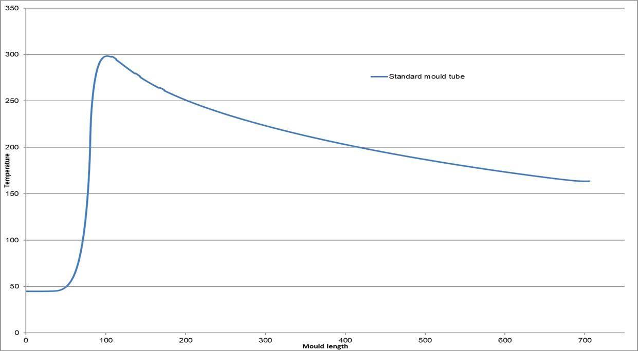
is inhomogeneous along the casting direction as well. In case of oil casting, the hot melt is provided via open stream pouring, resulting in a high thermal load in the meniscus and therefore the highest copper temperatures below the meniscus. The reason for this thermal load peak is the thin shell with its good contact to the wall, giving very good heat transfer. The attached graph of a thermal calculation shows the copper temperature over the length of a standard mould tube during casting including the extreme temperature peak below the meniscus level.
Fig.1 - Hot face temperature of standard mould tube vs. the mould length.
An inhomogeneous shell growth inside a mould is one reason for the negative impact on billet quality. A billet with such uneven shell thickness and its tendency for twisting creates an uneven wear inside the mould tube so that its lifetime will not reach the maximum potential.
Out of this knowledge, the task was generated to develop a mould tube with a moderated heat transfer in specific areas, in order to achieve a more homogeneous shell growth over the mould length. Therefore, the target is to produce a high-quality billet by smoothening the heat peak in the top part of the mould, without influencing the total shell thickness at the exit of the mould tube.
The physical properties of copper alloys (such as CuAg) with its drop in hardness at high temperatures is taken into consideration. For protecting the copper against overheating, all design changes of reducing the heat transfer have to be made on the inner surface of the mould tube. Otherwise, with a significant reduced heat transfer from the mould into the water, the copper temperature will increase and might reach the softening or recrystallization temperature when copper changes its physical properties. For example, the hardness will drop and a plastic deformation will occur much earlier. A worst-case safety scenario would be a collapsing mould with water penetration into the liquid steel. Therefore, the target of heat transfer reduction at the hot face is
reached by creating specific areas for moderation. This changed heat transfer from the steel to the mould improves the mentioned problems like the heat peak and the resulting inhomogeneous shell growth.
Using the texture, the idea is to influence the heat transfer by working with the material available in the mould such as air, lubrication (cracked oil) and FeO3 etc. The thermal conductivity of this combined material is much less compared to copper.
For example: CuAg ≈ 377 W/(m∙K) Casting Oil ≈ 0.16 W/(m∙K) Casting Powder ≈ 1-2 W/(m∙K) Air: ≈ 0.025 – 0.081W/m∙K
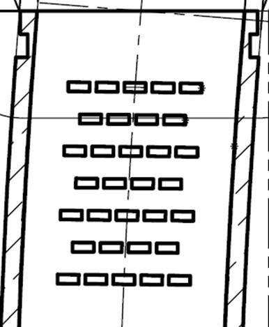
To utilize this resource of low conductivity material as an active heat transfer moderating tool in casting, KME brought in areas of specific topography at the mould top (Fig 2). By thus changing the heat transfer directly at the steel shell, an increase of the copper temperature can be avoided.
Fig.2 - Agglomeration areas in the top of a textured mould tube.
This deliberated zone of low conductivity material reduces the heat transfer and the heat absorption of the mould in such areas respectively and moderates the shrinkage of steel from top to bottom. In calculating the overall thermal conductivity, the heat peak is smoothed and the grown shell is created with less inner stress. Please see below the graph of a thermal calculation comparing a standard mould tube and a textured mould tube. (Fig. 3)
Fig.3 - Hot face temperature in the middle of the faces of the mould tube vs. mould length (textured & standard).
Reducing the heat peak shown on the calculated graph above results in a low stress steel shell with less geometrical defects with a more homogenous contact to the mould and consequently the overall heat transfer will not drop significantly. For this reason, when looking at the cross section, the shell thickness at the exit of the mould tube is more homogenous.

The hot face temperature and the thermal stress of the mould at meniscus level decreases and prevents the copper mould tube alloy (such as CuAg) from overheating. In addition to the temperature reduction, the textured structure improves the effect of lubrication during casting as the slots are amongst other things filled with cracked oil, working as an oil/lubrication reservoir.
A calculation of standard mould tube with and without the texture (filled with oil) shows a decrease of approx. 25°C (from 300°C to 275°C which is about 10%)
Mould tube: Size: Height: Casting radius: Wall thickness: Material: Coating: 160 mm x 160 mm 800 mm 9000 mm 13 mm CuAg-GS neglected
Filler material inside the texture: Casting oil: λ = 0.16 W/m∙K Air: λ = 0.025 – 0.081 W/m∙K
Thermal boundary conditions: HTC (mould - strand): 6.43–2.7kW/m²∙K at (1500 – 900 °C) Cooling water velocity: ~ 10 m/s Cooling water temperature: 35 – 40 °C
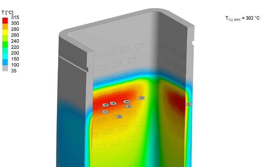
Fig.4 - Thermal calculation without texture.

Fig.5 - Thermal calculation calculation texture filled with oil.
Another positive effect of a cut heat peak is the reduction of the diffusion process of harmful elements into the copper. The negative effect of harmful elements such as Zn and S is due to their behaviour in combination with copper. Zinc is a "tramp" element coming from the steel (scrap) that diffuses into the copper when exposed to high temperatures for a prolonged time. To reach the copper these harmful elements have to pass the inner coating of the moulds. Most of the moulds for long product and open stream casting in use worldwide are only Chromium coated. This layer of about 0.1 mm thick electroplated hard-chromium does not stop the harmful elements because it contains a dense network of micro cracks. Due to the presence of these micro cracks, the zinc can diffuse into the copper quite easily.
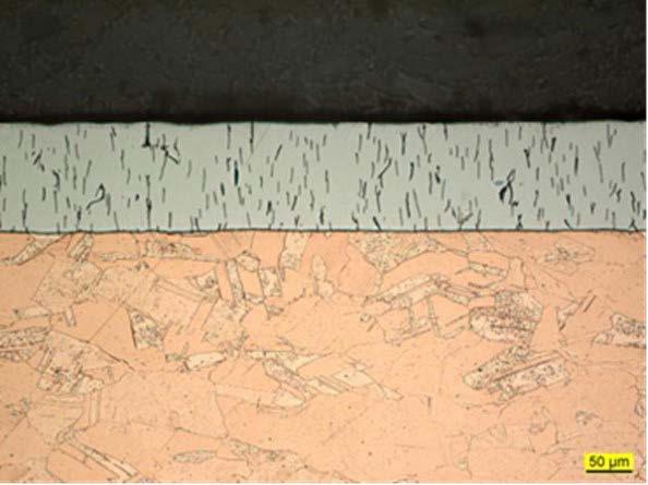
Fig.6 - Hard chromium with micro cracks.
After penetrating the copper, the base material is damaged: Higher zinc levels in the steel and higher local temperatures lead to the development of hard and brittle (bulky) brass phases at the copper surface, which accelerate the development of chrome chipping and cracking to the ductile copper. (4)
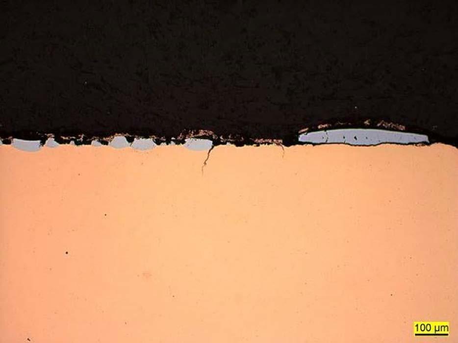
Fig.7 - Slight brass formation on the exposed surfaces.
Additionally, sulphur from the steel, or very often from mineral or synthetic casting oil, can penetrate through the chrome micro cracks into the copper. This penetration of sulphur in the copper damages the chrome due to the forming of voluminous, brittle copper-sulphides at elevated temperatures. Additionally cracks due to sulphur corrosion are generated. (5)
In addition, the very different coefficients of thermal expansion of Cr (~ 6x10⁻⁶ 1/K) and Cu (~ 17x10-6 1/K) make things more complicate. Therefore, you can often find an enlarged macro cracking in combination with high thermal stress. That is the reason why low quantity of heats might be sufficient for this type of damage if the temperature is high enough.
Appreciable diffusion in solid material starts around 0.4 x Ts (Ts = melting temperature in Kelvin) and increases exponentially at higher temperatures (6). The most common mould material for long product casting is CuAg with a melting point of 1083°C (7). The resulting appreciable diffusion start temperature for this copper alloy is theoretically 269°C. The exponentially increasing diffusion is the reason that the damage of the mould tube in the meniscus area speeds up very fast at higher temperatures. Due to the lower copper temperature in the texture zone, the diffusion process is slower in that area, resulting in higher lifetime especially for scrap-based steel production. The combination of both factors, the reduced copper temperature and the moderated heat transfer in the top part of the copper mould, results in an excellent mould performance in continuous casting.
The delayed attack in the meniscus area can be seen by comparing a standard mould and a textured mould from the same machine in a mini mill after casting 1500 heats. Size: 160 mm x 160 mm Strands: 5 Radius: 6 m Casting Speed: approx. 2.8 m/min Steel Grades: Rebar Ladle weight: 100 to

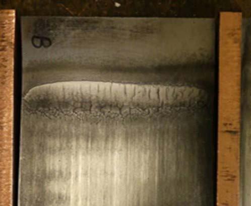
Fig.8 - Meniscus of moulds after 1500 heats.
Thus both improved billet quality and increased mould lifetime are the reasons that the KME textured mould is growing popularity around the world.
REFERENCES
[1] Definition and causes of continuous casting defects. ISI publication 106 [2] Metallurgie des Stranggießens Prof. Dr.-Ing K Schwerdtfeger pp.242-255 pp 262-279 [3] Stranggießen von Stahl Hans Schrewe, pp. 104-109 [4] KME Special Products GmbH & Co. KG, AMT® – Advanced Mould Technology pp21 [5] KME Special Products GmbH & Co. KG, AMC® - ML Coating for Mould Tubes [6] Handbuch Hochtemperatur Werkstofftechnik, Prof. Dr. Ralf Bürgel pp 18-19 [7] DKI (Deutsches Kupfer Institut) Datenblatt


