2.3 International case study – Lords Cricket Stadium :Brief History:-
Lord's today is not on its original site; it is the third of three grounds that Lord established between 1787 and 1814. His first ground, now referred to as Lord's Old Ground, was where Dorset Square now stands. His second ground, Lord's Middle Ground, was used from 1811 to 1813 before being abandoned to make way for the construction through its outfield of the Regent's Canal.
Thomas Lord opened his first ground in May 1787 on the site where Dorset Square now stands.
The White Conduit moved there from Islington soon afterwards and reconstituted themselves as Marylebone Cricket Club.
The "Middle Ground" was on the estate of the Eyre family, who offered Lord another plot nearby; and he again relocated his turf.
The new ground, on the present site, was opened in the 1814 season. The earliest known match was MCC v Hertfordshire on 22 June 1814.This is not rated a first-class match. MCC won by an innings and 27 runs.
The next match known to have been played at Lord's, from 13 to 15 July 1814, was the earliest first-class one, between MCC and the neighbouring St John's Wood club, which had several guest players for the occasion, including five leading professionals. MCC won by 4 wickets.
The first test match and ODI matches was played between England and Australia ind 1884.
The current ground celebrated its two hundredth anniversary in 2014. To mark the occasion, on 5 July an MCC XI captained by Sachin Tendulkar played a Rest of the World XI led by Shane Warne in a 50 overs match.
. The present Lord's ground is about 250 yards (230 m) north-west of the site of the Middle Ground. The ground can hold 30,000 spectators.
Lord’s hosts five icc cricket world cup matches, including its fifth men’s final. India won world final at this very stadium beating Windies by 43 runs in 1983.
Akhil Manikyam. R
1
()
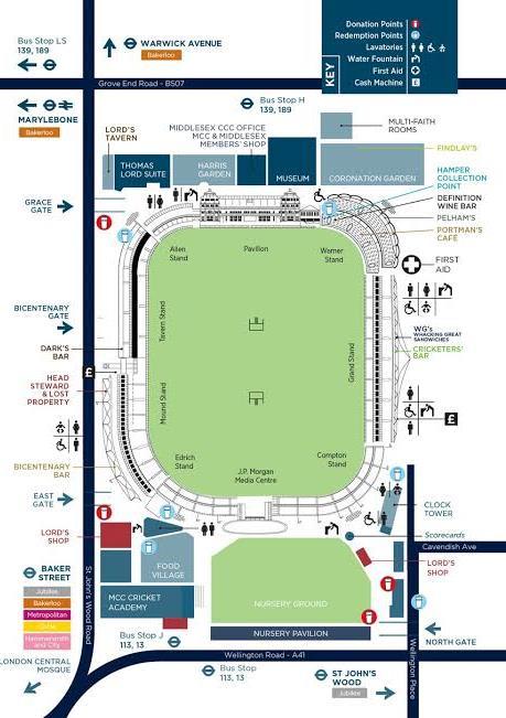
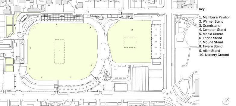
Figure 2 Site plan of lords cricket source: lords cricket stadium.co
SITE PLAN PLAN SHOWING DIFFERENT STANDS
SITE PLAN
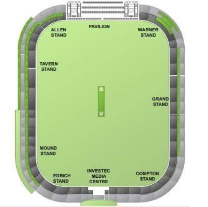
Figure 1 stands of Lord's cricket stadium source: lordscricketstadium.com
Stands at Lord's.
1.Pavilion
3.Grand Stand
5.Edrich Stand
7.Tavern Stand
2.Warner Stand
4.Compton Stand
6.Mound Stand
8.Allen Stand
Many of the stands were rebuilt in the late 20th century. In 1987 the new Mound Stand, designed by Michael Hopkins and Partners, was opened, followed by the Grand Stand (by Nicholas Grimshaw) in 1996.
] The Media Centre, opposite the Pavilion between the Compton and Erich Stands, was added in 1998-9; designed by Future Systems it won the Royal Institute of British Architects' Stirling Prize for 1999.
] The ground can currently hold up to 28,000 spectators. The two ends of the pitch are the Pavilion End (south-west), where the main members' pavilion is located, and the Nursery End (north-east), dominated by the Media Centre.
. In 1923, the W. G. Grace Memorial Gates were erected at the St John's Wood Road entrance to the ground.
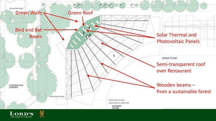
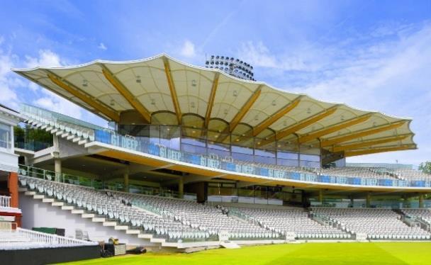
THE WARNER STAND:-The most striking feature of the new stand is its almost wing-like roof, formed using white oak glulam beams and profiled steel, with a high-tech translucent fabric canopy that shades spectators but also allows through some natural light.
Locating and securing the cantilevered glulam beams – at that time the longest ever created using American white oak – was a precision task.
The new stand is right in the corner of Lord’s, making it the hardest part of the ground to access. This also presented some challenges during construction, but BAM used a 200-ton mobile crane (positioned for a tight, three-day window on a track-way on the famous Lord’s turf) to lift the glulam beam and pre-cast terraces into place.
Akhil Manikyam. R
2
Figure 3 Different stands of stadium source :lordscricketstadium.com
Figure 5 Warner stand source :lordscricketstadium.com
Figure 4 Warner stand source :lordscricketstadium.com
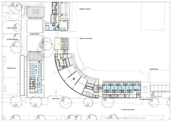
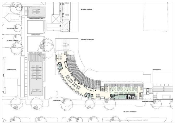
FLOOR PLANS OF WARNER STAND


Mound Stand:-
The brick arcade of the original 19th century Mound Stand was retained and extended, making the underside an attractive and usable public concourse. The seating tiers on the mound were renewed. A new steel superstructure, supported on only six columns, to minimise disruption to views, are linked by a plate girder, from which lattice trusses cantilever out, like ribs from a spine, forming the skeleton of a threestorey structure, which hovers over the mound below. Private boxes and dining rooms hang below the skeleton, while service rooms occupy the space between the ribs. A tier of raked seating backed by openair restaurants and bars sits on top.
The six columns continue up to become masts supporting a flamboyant canopy of PVC-coated, polyester fabric. The whole structure is held back by tension members anchored to the ground and strapped to the brick piers below to stiffen them.
The private boxes have folding, frameless glass doors opening onto a raking balcony facing the wicket, with party walls of fair faced concrete blockwork and rear walls, onto the corridor, of glass blocks
fullheight panels.
Allen Stand:-MEDIA BOX:-
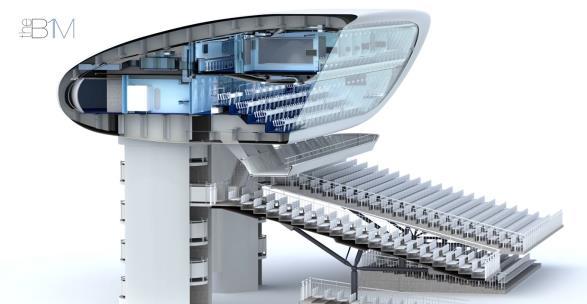
The media box was designed from 1995-98.
The construction was started in the year 1998 and completed in the 1999. The media box capacity is 100 people, which stands 15mts above the ground.
3 Akhil Manikyam. R
in
Figure 7 Warner stand floor plan source :lordscricketstadium.com
Figure 6 Warner stand floor plan source :lordscricketstadium.com
Figure 9 floor plan Allen stand source :lordscricketstadium.com
Figure 8 floor plan Allen stand source :lordscricketstadium.com
Figure 11 section of media box source :lordscricketstadium.com
FLOOD LIGHTS
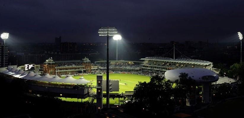
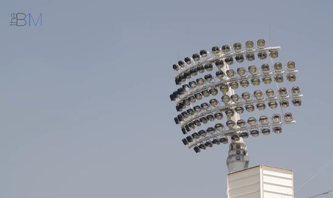
Flood lights was installed in 2009. 3 floodlights were used on each of the four head frames, each one incorporates a 2kw day-light lamp producing 200,000 lumens. The lighting design ensured vertical illuminance of 2,000 lux over the central wicket, 1,800 lux over the inner field and 1,300 lux over the boundary and horizontal illuminance uniformities in excess of 0.8. Bespoke cowls and louvers were fitted to the floodlights to ensure effective control of overspill.


FUTURE MASTER PLAN :-

4
R
Akhil Manikyam.
Figure 13 view of media box source :lordscricketstadium.co
VIEW OF MEDIA BOX
VIEW OF INSIDE OF MEDIA BOX
Figure 15 view of flood lights source :lordscricketstadium.com
Figure 16 master plan of Lord's cricket stadium source :lordscricketstadium.com
Figure 12 view of inside of media box source :lordscricketstadium.com
Figure 14 view of flood lights source :lordscricketstadium.com
2.4 International case study – The Melbourne Cricket Stadium :Brief History:-
It was founded in 1838 and is one of the oldest sports clubs in Australia. The Melbourne cricket stadium was built 1853 and it has undergone numerous renovations. The Melbourne Cricket Club (MCC) also known as “THE G” is a sports club based in Melbourne, Australia.
The first public grandstand was a 200-metre long 6000-seat temporary structure built in 1861. Another grandstand seating 2000, facing one way to the cricket ground and the other way to the park where football was played, was built in 1876 for the 1877 visit of James Lillywhite's English cricket team. It was during this tour that the MCG hosted the world's first Test match.
The foundation stone was laid by Prince George of Wales and Prince Albert Victor on 4 July and the stand opened in December that year. It was also in 1881 that a telephone was installed at the ground, and the wickets and goal posts were changed from an east-west orientation to north-south.
. In 1882 a scoreboard was built which showed details of the batsman's name and how he was dismissed.
The MCG was the home of Australia's first full colour video scoreboard, which replaced the old scoreboard in 1982, located on Level 4 of the Western Stand.
A second video screen added in 1994 almost directly opposite, on Level 4 of the Olympic stand.
In 1985, light towers were installed at the ground, allowing for night football and day-night cricket games. the stadium is oldest in Australia, which is 171 years old.
The total capacity of the MCG is 100,018. This includes 95,000 seats and approximately 5000 standing room spaces.
SITE PLAN:-
5
Akhil Manikyam. R
()
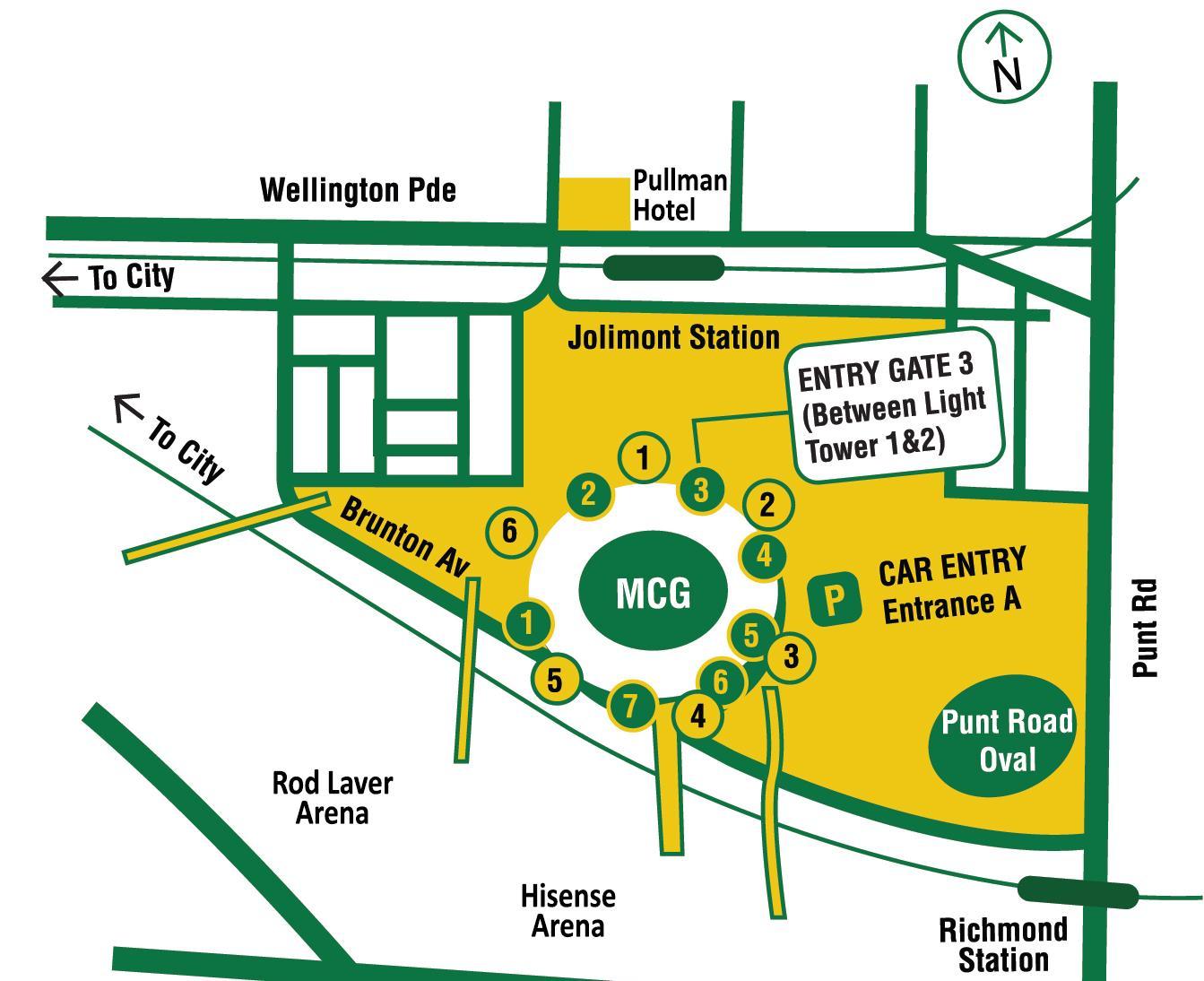
Figure 17 Site plan of Melbourne cricket stadium source:melbournecricketstadium.com
The is located in Melbourne in Australia. The site area is 89 acres , including Punt road oval ground. The site has road access on all the sides of the site which makes the stadium more access. The stadium is situation between two railway line which makes people the access the stadium better The connecting stations are Richmond Station and Jolimont Station. The 171m x 146m field at the MCG is surrounded by four stands - Great Southern Stand, MCC Members' Reserve, Olympic Stand and Pons ford Stand.
The stadium has 7 access gates to enter the stadium and 6 flood lights. The MCC is also an umbrella organisation for other sports, such as Australian football, baseball, bowls, field hockey, golf, lacrosse, netball, target shooting, squash and real tennis.
6 Akhil Manikyam. R
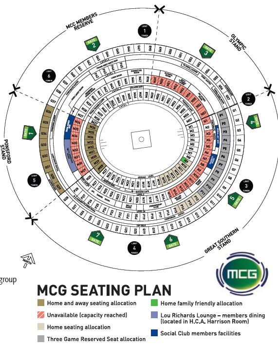
Figure 18 seating layout source :source:melbournecricketstadium.com
Gates 1, 2 & 3. (Three Atrium Entrances) as Underground car parking for spectators.

Roof Structure:-
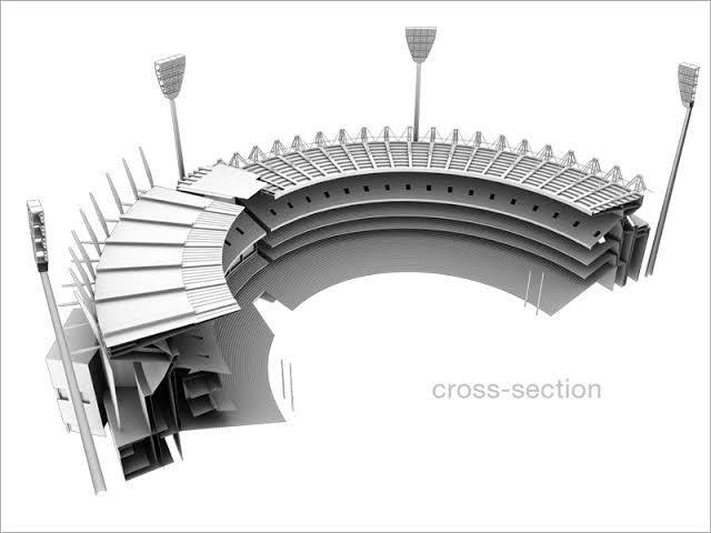
The main roof has 1,100 tonnes of structural steel and 5,300 lineal metres of steel cable supports
- 6,000 sq. metres of glass roof area and 14,000 sq. metres of metal deck roof
- 2,900 tonnes of other structural steel
- 72,000 metres of TV broadcast cabling
The main roof covers 80% of patrons.
The ground level stands has no roof cover.
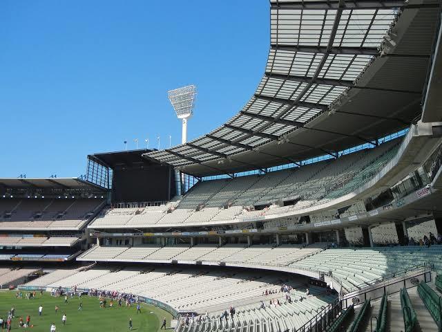
To support the roof structure it has steel member which is projected on top , which helps in cantilever the roof , which avoids the columns below which would be the obstruction to the spectators
7
Akhil Manikyam. R
Figure 19 section of stadium source:melbournecricketstadium.com
Figure 21 view of stands source:melbournecricketstadium.com
Figure 20 3d section of stadium source:melbournecricketstadium.com
Flood Lights:-
1984 - Six light towers averaging 75 metres in height (plus 10m high head frames) were built outside the stadium perimeter. The towers are made of 20mm steel plate and are 4.2 metres in diameter at the base. They were commissioned on December 3.
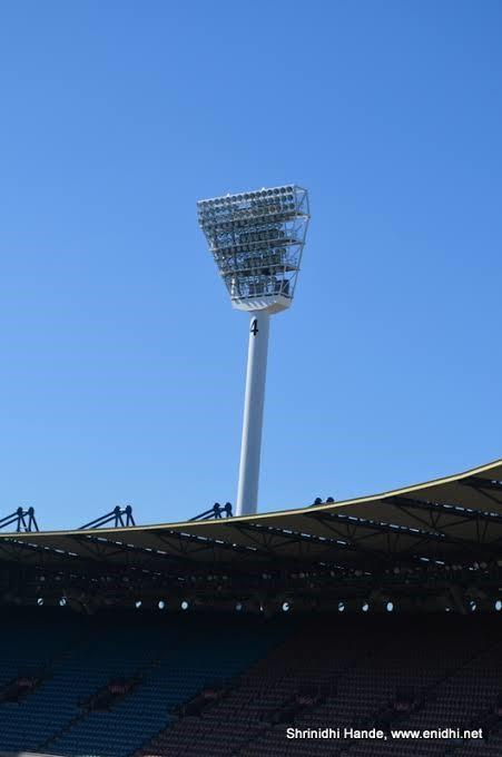
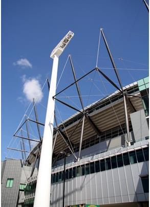
The light tower system comprises of six light towers which stand approximately 75 metres high (equivalent to a 24-story building) with the head frame a further 10 metres higher (85 metres overall).
The foundations for the towers consist of four reinforced concrete piers which are set down in depth from seven to 12 metres depending on the sub surface structure.
Each of the hollow tubular steel towers contains about 130 tonnes of steel. The diameter reduces from 4.2 metres at the base to two metres at the top. There are between 12 and 14 landings connecting ladders inside each tower.
The head frames of the towers are angled in at 15 Degrees in order to provide best possible level of light. Each light tower has an average of 140 no. 2KW (2000-Watt) Metal Halide lamps within the head frame. The lamps have an effective life of approximately 5000 running hours and about 30 lamps on average are replaced each year .The lights take approximately 10 minutes to become fully illuminated. If the lights are turned off they cannot be turned back on for another 15 minutes as they require time to cool down and then warm back up.
ELEVATION OF STADIUM

8
Akhil Manikyam. R
Figure 23 view of flood lights source:melbournecricketstadium.com
Figure 24 elevation of stadium source:melbournecricketstadium.com
Figure 22 view of flood lights source:melbournecricketstadium.com

9 Akhil Manikyam. R 2.5 COMPARATIVE ANALYSIS OF CASE STUDY OF STADIUMS
Table 1 Comparative Analysis of case study of stadiums
Chapter 3 : DATA COLLECTION
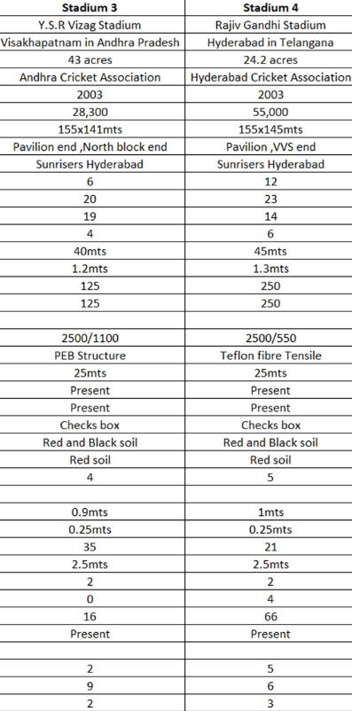

10 Akhil Manikyam. R COMPARATIVE ANALYSIS OF CASE STUDY OF STADIUMS
Table 2 Comparative Analysis of case study of stadiums
Cricket
The term cricket is variously thought to be derived from the target aimed at and the implement used to defend it. In the former case it is argued that the word is related to German words which mean something related to the wickets. Others believe the word has an English origin. The game had started off in England, so the inception of the word is more probable to be coming from an English background.

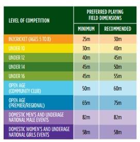
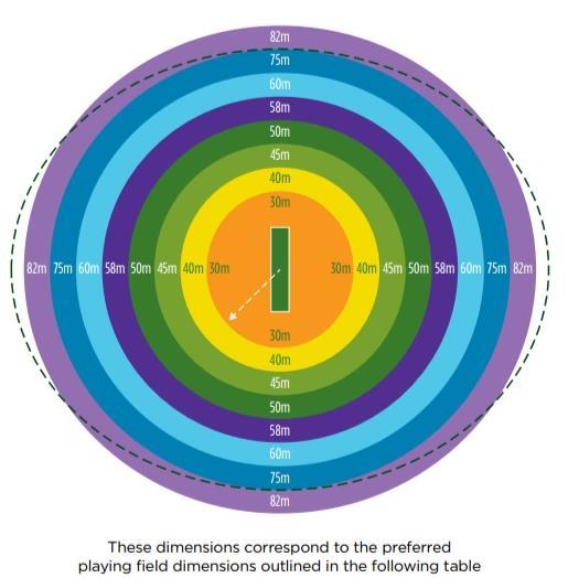
3.1 Cricket field
The entire area of grass, marked off by a boundary line around its outer edge, on which a game of cricket is played, as distinguished from the ‘pitch’ or central area between the two wickets. ( Steven Lynch, Wisden 2006, p 100
CRICKET PITCH
The area of ground between two sets of stumps is called a cricket pitch. It has length of 22 yards. The surface of the pitch is made up of clay. It is the main play area of cricket where the batsman stands.
11
Akhil Manikyam. R
Table 3 ground dimensions
Figure 25 cricket pitch source: aitiusdirctory.com
3.2 GEOMETRICAL FORM OF GROUND
A cricket ground is an elliptical stretch of grass where the game of cricket is officially played. Though there is no fixed shape of a cricket ground, deviating too much from a low-eccentricity ellipse is largely discouraged. The size too varies from 90 to 150 meters (100-160 yards) across. In recent times, the grounds are getting smaller by the day in order to propagate high-scoring matches. On most of the cricket grounds there is a rope that demarcates the perimeter of the field. This is known as the boundary.
BOUNDARY :-A boundary defines the limits of the playing area and it is marked by a line, a fence or a rope. If a player or any other foreign object disturbs a part of the boundary during play, then the boundary is considered to be at the same position as it was before the disturbance.
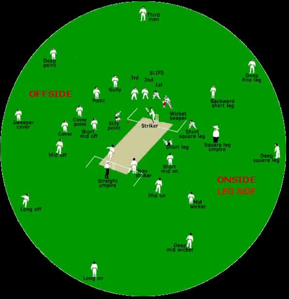
12 Akhil Manikyam. R PLAYERS POSITION ()
Figure 26 fielding position source: aitiusdirctory.com
References can be made to different sections of the boundary in terms of nearest fielding positions - for instance third-man boundary or mid-wicket boundary.
A ball in play, when touches or crosses the boundary without a bounce, gives six runs to the batsman. When the ball touches or crosses the boundary with one or more than one bounce, it gives four runs to the batsman. If a fielder touches the boundary while he is still in contact with the ball, the batsman is awarded four or six runs accordingly.
A turf pitch is 20.12m long and 3.05m wide. A non-turf pitch is a minimum length of 17.68m and a minimum of 1.83m wide. A pitch is bounded at either end by the bowling creases and a set of wickets in the centre of the bowling crease.
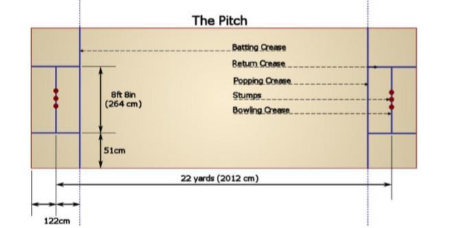
A pitch is generally made up of two kinds of surfaces. The surface generally used is a natural surface with a grass cover. The grass is usually cut extremely short so that the surface becomes flat.
At times, artificial turf is also used for the preparation of the pitch. This can be a slab of concrete overlaid with a coir-mat. Artificial pitches are mostly used in exhibition matches.
CONSTRUCTION OF PITCHES
1. Compacted Bed
2. Base (compacted Gravel and Sand)
3. Layer of clayey loam and

4. Top Soil
Akhil Manikyam. R
13
Figure 27 cricket pitch source: aitiusdirctory.com
Figure 28 typical section of pitches
PITCH
COMPOSITION
DRAINAGE
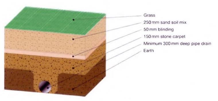
PITCH DRAINAGE: The drainage for the ground has been designed such that the entire ground gets dried within 15 minutes even after very heavy rainfall. A dense network of lateral pipes of 110mm dia collects the water penetrating the turf and drains to main pipes of 160mm dia which finally drains off to the inner peripheral drain.
Adequate drainage is a necessity, and the above methods may need to be supplemented to avoid standing pools of surface water after heavy rainfall and to minimize expensive 'down-time' in wet weather. There are basically two methods of drainage - passive and active.
The passive approach relies on gravity to drain away the water, and one method of enhancing the basic system described above would be the cutting of deep `slit drains' into the subsoil by specialist machine, and filling these with sand or fine gravel to help surface water flow down quickly into the land drains. This is quite expensive and needs to be carefully coasted before a decision is taken.
The active approach uses pumps, usually activated by water-sensing electronic devices in the field, to literally suck the water off the pitch and into underground storage chambers, thus clearing the surface very quickly and maximizing the availability of the pitch for revenue-generating activity. Special drainage pipes may be laid for this purpose, or alternatively cellular technology may use the same underground network of pipes both for irrigation and drainage simply by reversing the direction of flow by computer control.
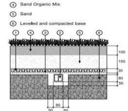
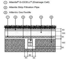
Drainage there are two types ;-1. Drain cell 2. Drain core
14 Akhil Manikyam. R
Figure 29 Layers of the playing field source : Stadia- 2007
Figure 31 section of pitches Stadia- 2007 IRRIGATION
Figure 30 section of pitches Stadia- 2007
Traditionally grass pitches have been watered by sprinklers, usually of the pop-up kind, but these are being challenged by underground water delivery systems. Using special porous low-pressure water supply pipes (or possibly the underground drainage system with the direction of flow reversed by computer control as suggested above) which allow a uniform `weep rate' along the whole length of the pipe, a steady supply of water - possibly mixed with fertilizer and weed-control additives - seeps directly to the grass root zone. The advantages that are claimed for sub-surface irrigation include:
. UNDERGROUND IRRIGATION PIPES ARE NORMALLY LAID BETWEEN 150 MM AND 350 MM BELOW THE SURFACE, SPACED FROM 450 MM TO 900 MM APART; BUT SPECIALIST ADVICE MUST BE SOUGHT.
LIGHTING
It is essential to have good quality lighting so that the players can follow the movement of the ball travelling at high speeds, either struck by the batsman or bowled by the bowler. The illuminance must be uniform throughout the hall, with the background walls behind both batsman and bowler providing a good viewing contrast. Safety is paramount and the lighting system must taken into account the propulsion of balls at speed. The recommended minimum lighting level for an indoor cricket sports centre is between 1000 and1500 lux. These requirements are generally met by a system of horizontal, fluorescent luminaires, fitted with reflectors and mounted at right angles to the pitch. The reflectors must screen both batsman and bowler from direct view of this light source.
The International Standard for lighting cricket grounds is as follows:
1. non-televised training ─ 250 lux
2. non-televised match ─ 500 to 700 lux
3. televised match ─ 1400 lux
15 Akhil Manikyam. R
()
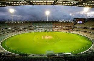
Figure 32 view of flood lights source:cricket.com
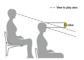
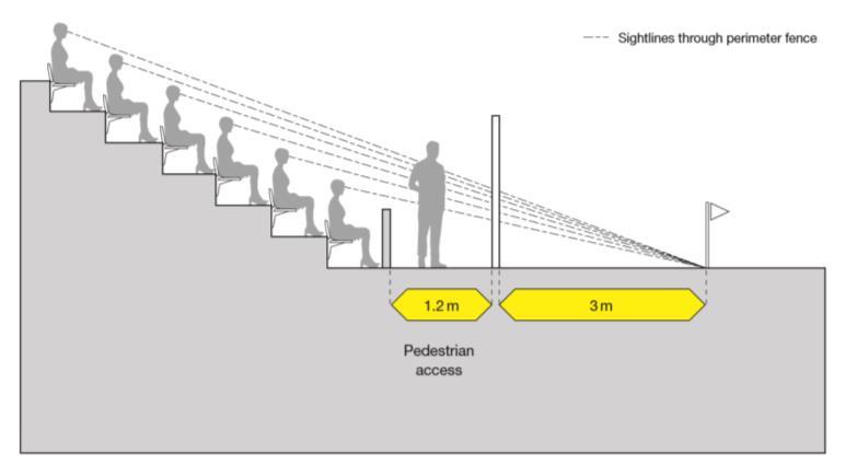
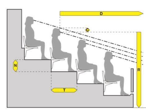
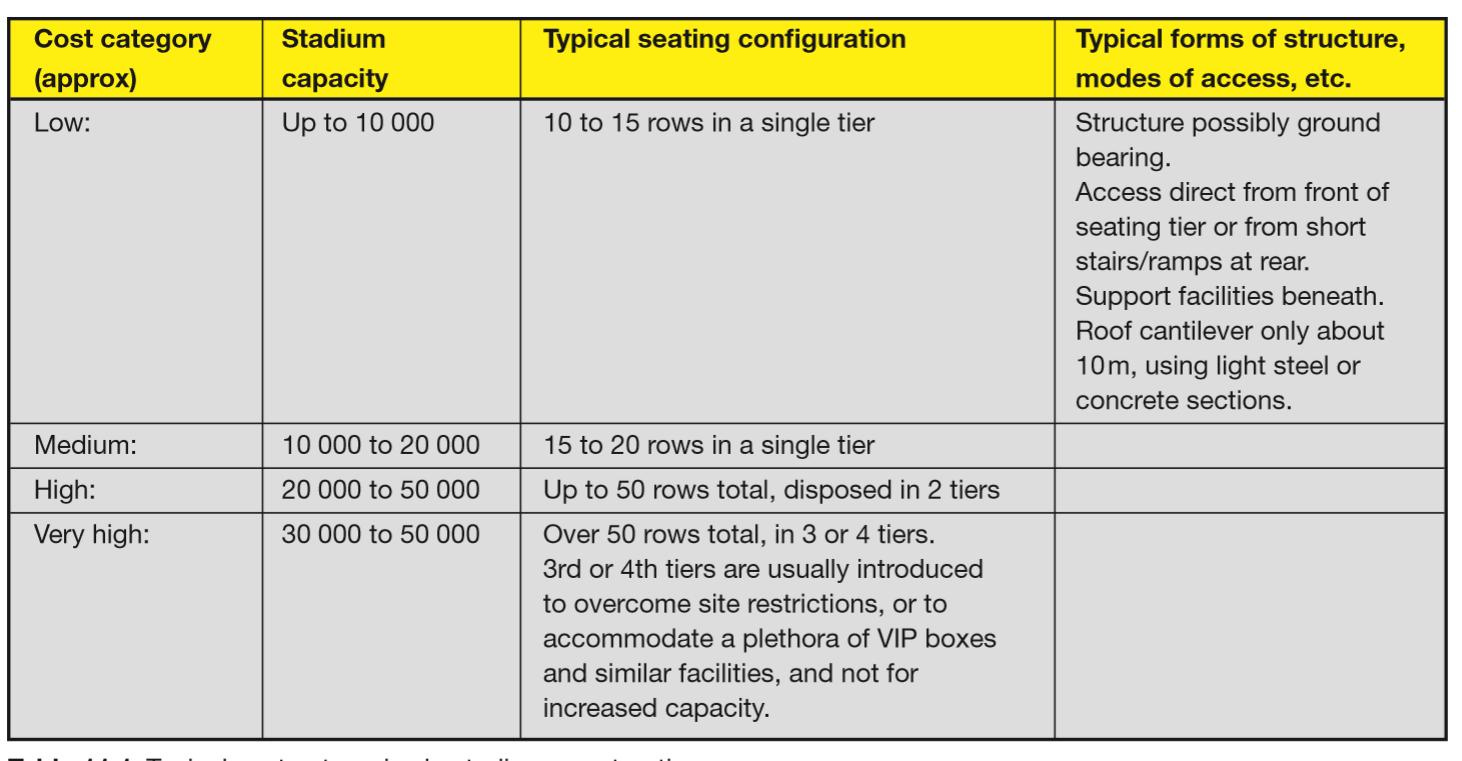
Having arrived at geometry which relates the spectator areas to the playing field so that the spectators can see the action clearly and without having to crane their necks, the next design tasks is the seats themselves. Seating design is a matter of reconciling four major factors: comfort, safety, robustness and economy.
16 Akhil Manikyam. R 3.3 SPECTATORS SEATING. ()
Table 4 Seating Capacity source: STADIA: A Design and Development Guide
Figure 34 sight line value source:Stadia-2007
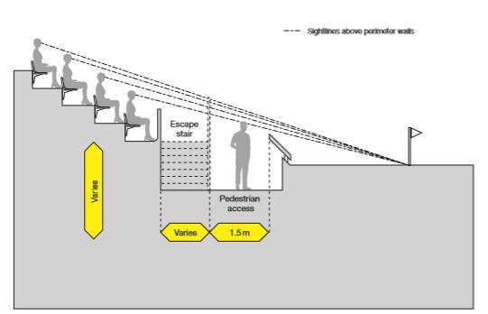
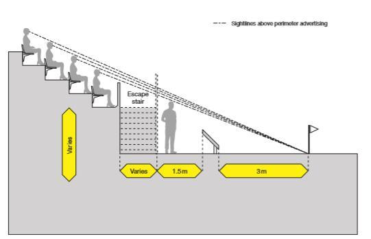
Figure 35 corridor width source:Stadia-2007
Figure 33 seating eye level source:Stadia2007
17 Akhil Manikyam. R
Figure 36 corridor width1 source:Stadia-2007
Figure 37 corridor width1 source:Stadia-2007

18 Akhil Manikyam. R
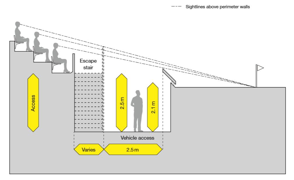
Figure 38 access moat source:Stadia-2007
Table 5 Wheelchair capacity source: Stadia
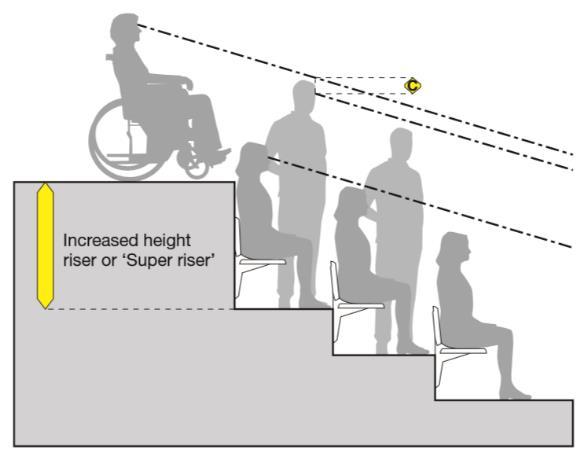
Figure 39 wheelchair sight line source:Stadia2007
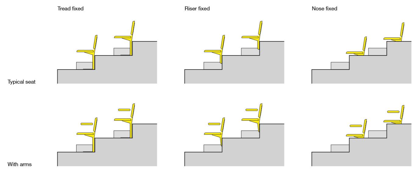
Figure 40 seating typologies source:Stadia-2007
RAKING ANGLE CALCULATION:-
19 Akhil Manikyam. R 3.4 RAKING ANGLE
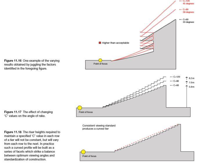
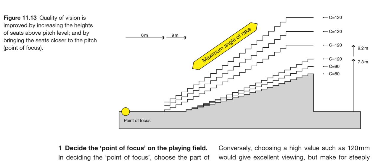
Figure 41 Raking angle calculation source:Stadia-2007
Figure 42 Raking angle calculation source:Stadia-2007
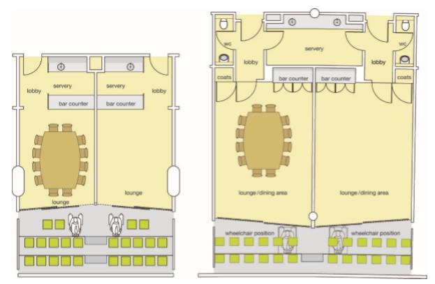
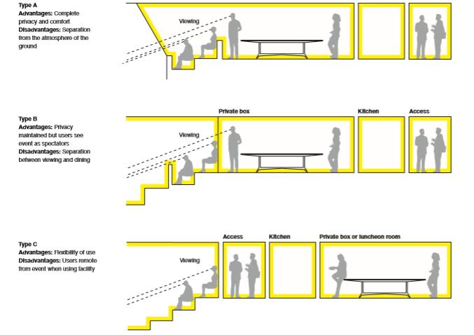
CONFRENCE ROOM
20
Manikyam. R VIP facilities
Akhil
Figure 43 VIP Boxes types source:Stadia-2007
Figure 44 Conference room source:Stadia-2007
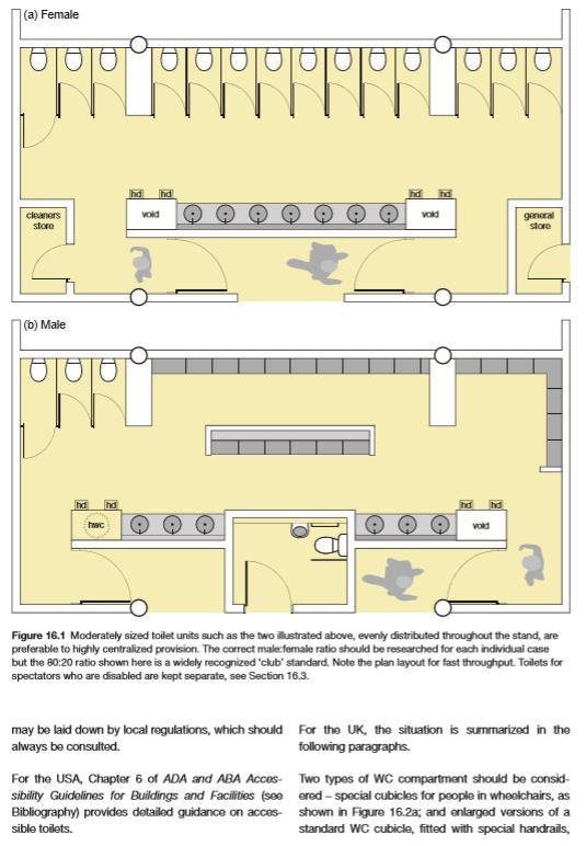
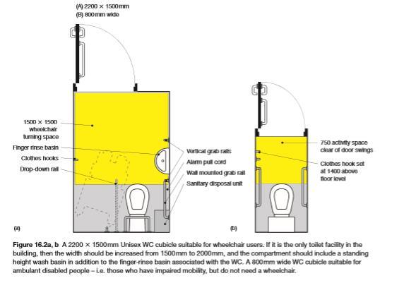
3.5 TOILET
Toilets and other ablutionary facilities may be needed for several individual types of stadium users in addition to those for the mass spectators. These facilities should be thought of if in conjunction with spectator toilets so as to minimize the number of sanitary appliances and drainage
21
Akhil Manikyam. R
Figure 45 Toilet calculations source:Stadia-2007
MEDIA FACILITIES


22 Akhil Manikyam. R
Figure 46 Handicap toilet source:Stadia-2007
Table 6 Toilet calculations source: Stadia
Table 7 Toilet calculation source: Stadia
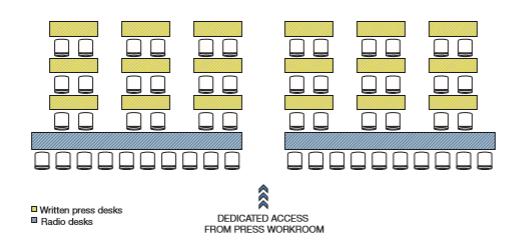
Facilities for media are an integral part of stadium design, not least because of the large sums of money that are now-a-days entered from the media rights for sporting events. These facilities involve the three main categories of public information and entertainment services- the press (including newspapers and magazines), radio and television. Clubs may also have their own media requirements club TV and websites.
23
Manikyam. R
Akhil
Figure 47 Media and radio centre source:Stadia-2007 SCHEMATIC SECTION
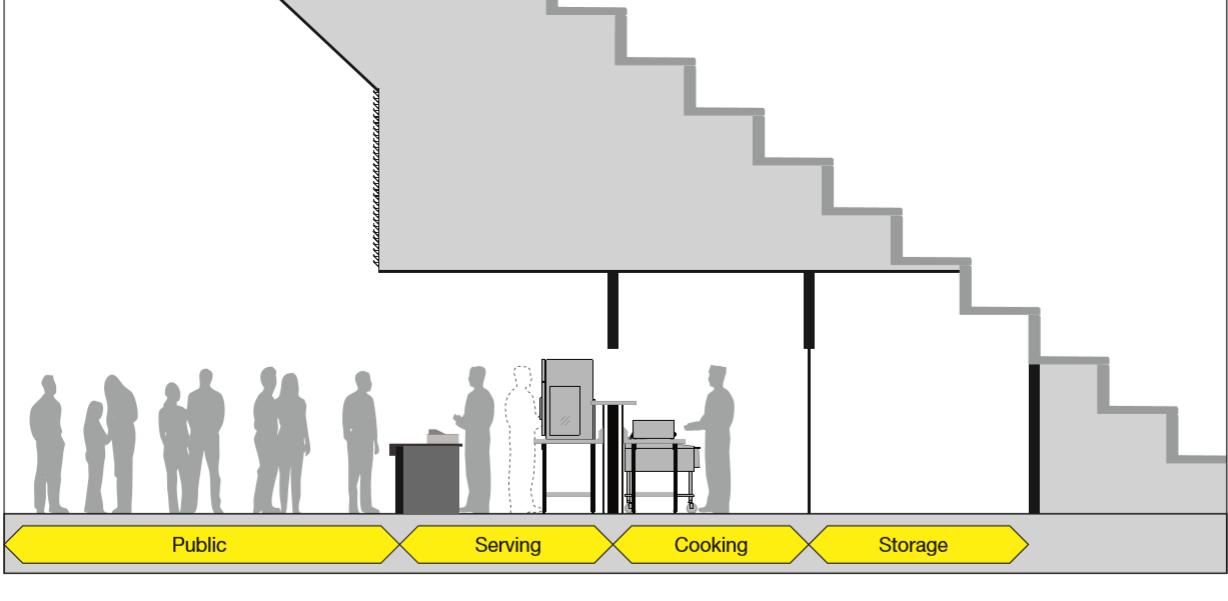
Figure 48 schematic section under tier FLOW CHART SHOWING PLAYER’S AND VIP’S FACILITES
PITCH ORIENTATION
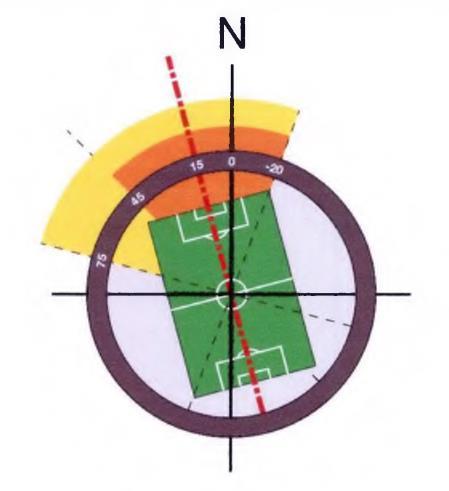
The cricket pitch orientation is extremely important because the game cannot be played across the direction of the wind. In order to play along the wind direction, the pith is oriented in the north-south direction, with a maximum deviation up to 15 degrees.
SHADING DEPTH AND ANGLE
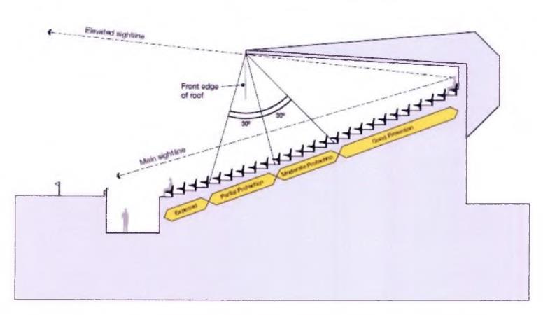
The shading depth and angle of the gallery spaces are important for comfort and quality of viewing so the spectators. The roof of the stadium provides such shading facilities to counter the direct sunlight and rainfall. For multi-tier gallery systems, the upper gallery provides shade to the lower one. The roof structure then provides shading for the upper gallery. Usually, half of the gallery must be shaded by the upper tier or the roof structure.
24
Akhil Manikyam. R
Figure 49 Pitch Orientation source:Stadia-2007
Figure 50 shading depth and angle source:Stadia-2007
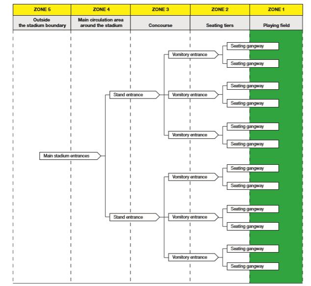
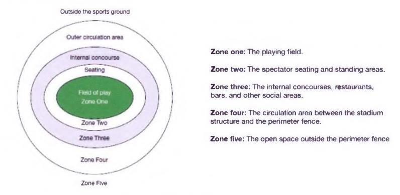
SECURITY ZONES
25 Akhil Manikyam. R
Figure 51 security zones source:Stadia-2007
Table 8 Security zones source: Stadia
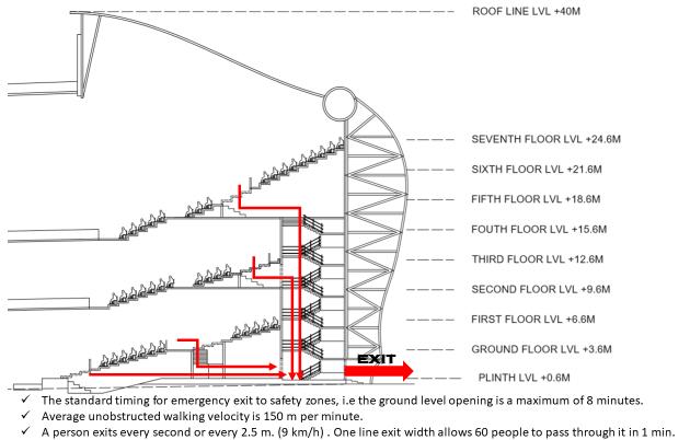
3.5 ENTRY AND EMERGENCY EXIT TIMING

The entry and exit timing has to be strictly controlled so that the spectators and all other people can be evacuated from the stadium within a limited given time. The standard timing for emergency exit to safety zones, i.e the ground level opening is a maximum of 8 minutes. This measurement is made from the basic walking velocities of the people through various modes of circulations such as horizontal and vertical circulation. This velocity, together with the unit width of the exit routes are calculated to form the efficient circulation system where the evacuation time of maximum 8 minutes is designed.
Average unobstructed walking velocity is 150 m per minute
A person exits every second or every 2.5 metres. (9 km/h)
One line exit width allows 60 people to pass through it in 1 minute
Average unobstructed walking on staircase 30m per minute (i ,8knvh». Spacing between people is 0.75 m.
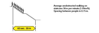
Timed exit analysis Safe exit time is regulation period minus exit time to place of safety.

26
Akhil Manikyam. R
Figure 52 showing running distance of fire exit source:Stadia-2007
Figure 53 showing fire exit source:Stadia-2007
Figure 54 showing running distance of fire exit source:Stadia-2007
3.6 BMICPA BY LAWS SET BACKS :-

Setbacks in dwelling house should be 15m away from any boundary line of the property.
Where the property abuts an urban road, the dwelling house building should be setback from the centreline of the road by 60m. Where the property abuts a village road, the building setback from the centreline of the road should be by 30m.
No development shall be allowed within 75 mtrs from the centreline of the Expressway.
27
Akhil Manikyam. R
Table 9 Site setbacks of BMICPA source: BMICPA
The maximum number of floors, percentage of plots coverage, FAR, height of the building for different plot size with existing road width as limiting factor are given in the following tables for various types of buildings like; Residential, Commercial, Public and Semi-Public, Industrial, etc.
1. Where the building lines are fixed in such cases the front setback or the building line, which is higher of the two, shall be considered as the setback to the building in the front.
2. In case of corner sites both the sides facing the road shall be treated as front side and regulations applied accordingly to maintain the building line on these roads and to provide better visibility.
3. In case of building facing more than two roads, the plot should be considered as corner plot taking two wider roads into consideration.
4. In case of sites facing roads both in front and rear, both the sides facing roads should be treated as front and other two sides not facing roads should be treated as right and the setbacks be applied accordingly.
5. In case where the plinth of the building is not parallel to the property line, the set back shall not be less than the specified setbacks at any given point on any side.
6. In case of building, which are existing prior to coming into force of these regulations, upper floor may be permitted according to the existing setbacks only, but limiting the F.A.R and No.of.floors according to the present regulations, subject to production of foundation certificate by a registered engineer.
7. In case of irregular plots the set-backs are to be calculated according to the depth or width at the points where the depths or widths are varying. Average setbacks shall not be considered in such cases.
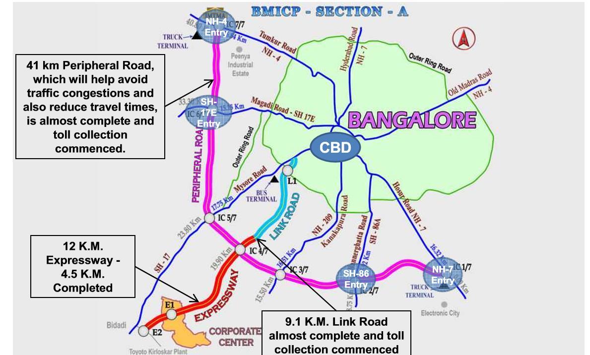
3.7 BMICPA PERIPHERAL ROAD MAP:-
The map showing the peripheral road network of Bangalore
28 Akhil Manikyam. R FAR :-
()
Figure 55 Map of BMICPA corridor source : BMICPA
Chapter 4 :SCOPE OF PROJECT
THIS STADIUM IS NOT ONLY TO PROVIDE SPACE FOR INTERNATIONAL MATCHES BUT ALSO PROVIDE A CRICKET ACADEMY TO YOUNGSTERS IN KARNATAKA.
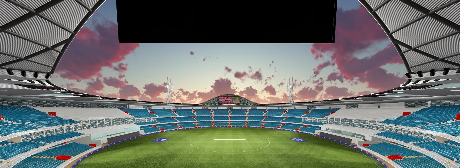
THIS STADIUM IS PLANNED TO ACCOMMODATE 90,000 SPEACTORS.
CRICKET MUSEUM.
AC VIEWING LOUNGE FOR VIP’S & VVIP’S
ACCOMODATION FOR PLAYERS & COACH .
DRESSING ROOM & TEAM MANGEMENT ROOMS.
PLAYER’S DINING AREA.
COPARATE BOXES.
MANGEMENT GROUND STAFF.
EQUIPMENT AREA.
SPECTATORS SEATING.
MULTI GYM FACILITY.
PRESS CONFERENCE ROOM
MEDIA ROOM.
MEDIA DINING ROOM.
DOPE TEST ROOM
MEDICAL ROOM
CONFERENCE ROOM.
COMMERICAL AREA.
CRICKET ACADEMY.
ADMIN BLOCK.
CLUBS HOUSE
PITCH PERPRATION ROOM.
UMPIRES ROOM.
COMMENTORY CABIN.
MATCH REFEEREE.
PRACTICE PITCHES.
PARKING.
29
Manikyam. R
Akhil
4.2 JUSTIFICATION OF THE SITE :-


THE SELECTION OF SITE TAKEN WITH THE MAJOR REQUIREMENTS THAT IS PEOPLE EASY TO ACCESS TO THE STADIUM.
SO TO THE SITE ALL 3 MODES OF TRANSPORT IS EASY TO ACCESS FROM THE MAJOR PARTS OF BANGALORE .

THE DEMOGRAPHICS SAYS , THAT BANGALORE AS PONTENTIAL OF SPECTATORS .
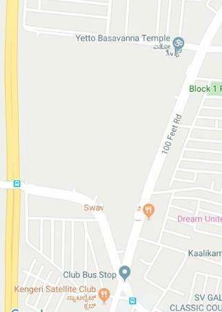
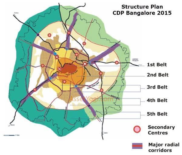
THE KENGERI SATELLITE TOWN WHICH IS CBD IS OF BANGALORE AND THERE A LOT OF INFRASTURCTURE NEEDED TO THE TOWN , THIS STADIUM PROJECT WILL PULL THE PEOPLE , TOWARDS THIS CBD AND TOWN WILL IMPROVE.
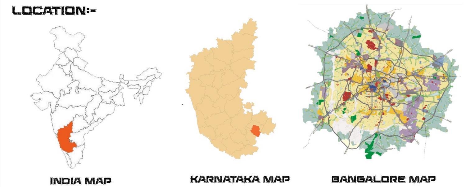
30
Manikyam. R 4.1BRIEF OF SITE
Akhil
Figure 58 article source:reddit.com
MASTER PLAN MASTER PLAN B M I C P A B M I C P A M
BMICPA MAP
SITE
Figure 56 Master plan source:CDP.com
BMICPA MAP
Figure 57 article source:reddit.com
4.3 SITE ACCESSIBILITY:-
SITE ANALYSIS


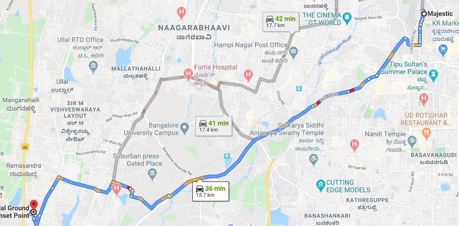
Distance From Majestic Bus Terminal:- 16.3 KMS (by bus & metro)
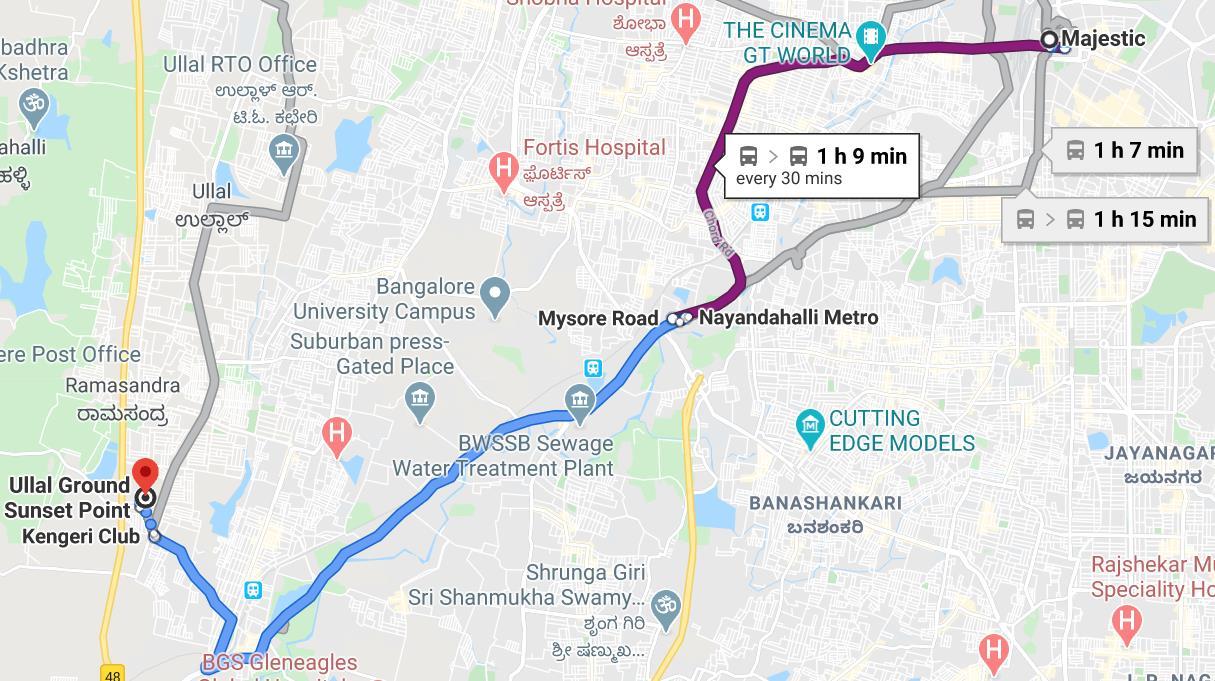
Time duration to reach the site from Bus terminal is 1hr 9mins
Distance From Majestic Bus Terminal:- 15.7 KMS (by car)
Time duration to reach the site from Bus terminal is 36mins
31 Akhil Manikyam. R
Distance From Majestic Bus Terminal:- 17.4 KMS (by bus)
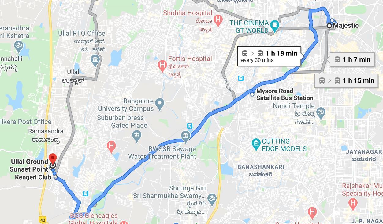
Time duration to reach the site from Bus terminal is 1hr19mins
Distance From Bangalore Airport:- 49.6KMS (by car)
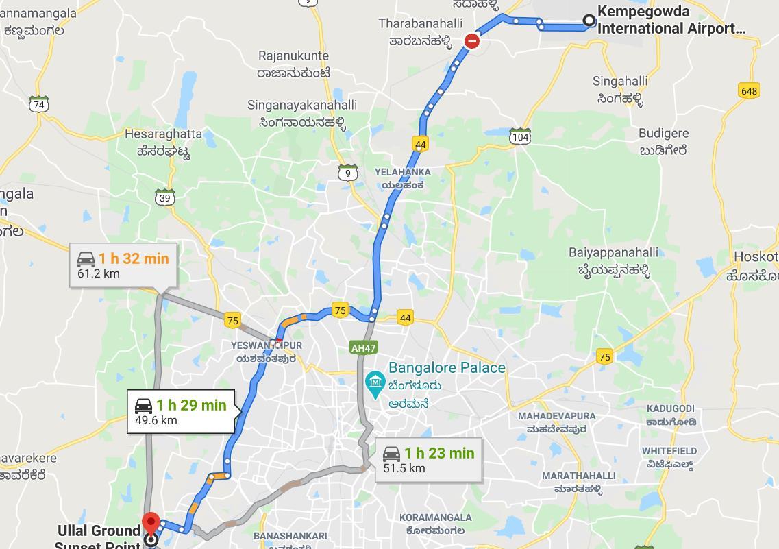

Time duration to reach the site from Bangalore airport is 1hr29mins.

32
R
Akhil Manikyam.
DISTANCE FROM NEAREST BUS TERMINAL:3.9Kms
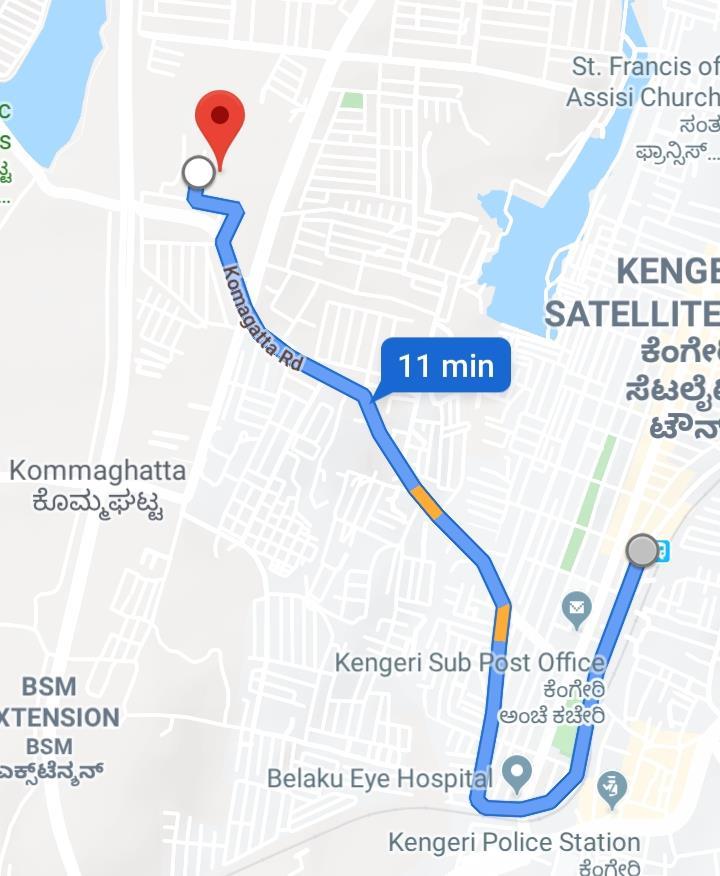

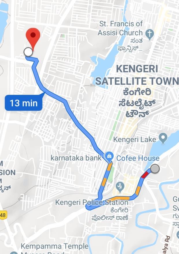
Time duration to reach the site from


DISTANCE FROM NEAREST METRO STATION:2.6 kms
Time duration to reach the site from metro station is 9mins
DISTANCE FROM NEAREST METRO STATION:2.6 kms
Time duration to reach the site from metro station is 9mins
DISTANCE FROM NEAREST RAILWAY STATION:- 2.6 Kms
Time duration to reach the site from Railway station is 9mins
DISTANCE FROM NEAREST RAILWAY STATION:- 2.6 Kms
Time duration to reach the site from Railway station is 9mins
33 Akhil Manikyam. R
DIFFERENT MODES TO REACH THE SITE:-
4.4 SITE SURROUNDINGS


34 Akhil Manikyam. R
Figure 59 site surroundings source: author
AVERAGE TEMPERATURE
AVERAGE TEMPERATURE
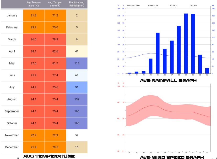
The Kengeri lies on 799m above sea level Kengeri's climate is classified as tropical.
In winter, there is much less rainfall in Kengeri than in summer.
This climate is considered to be Aw according to the Köppen-Geiger climate classification
The temperature here averages 24.5 °C | 76.1 °F. In a year, the rainfall is 856 mm | 33.7 inch.
Precipitation is the lowest in January, with an average of 2 mm | 0.1 inch. With an average of 166 mm | 6.5 inch, the most precipitation falls in September.
At an average temperature of 28.1 °C | 82.6 °F, April is the hottest month of the year. December has the lowest average temperature of the year. It is 21.4 °C | 70.5 °F.
Between the driest and wettest months, the difference in precipitation is 164 mm | 6 inch. During the year, the average temperatures vary by 6.7 °C | 44.1 °F.
35 Akhil Manikyam. R 1.5 CLIMATIC ANALYSIS
Figure 60 kengeri weather report source: weatherreport.com
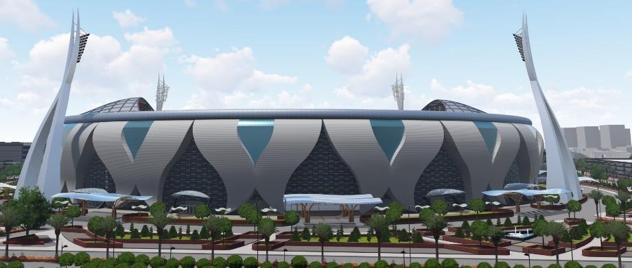
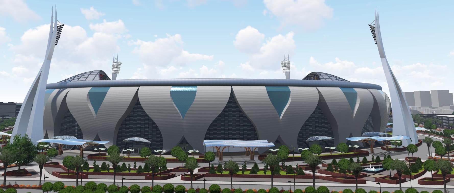
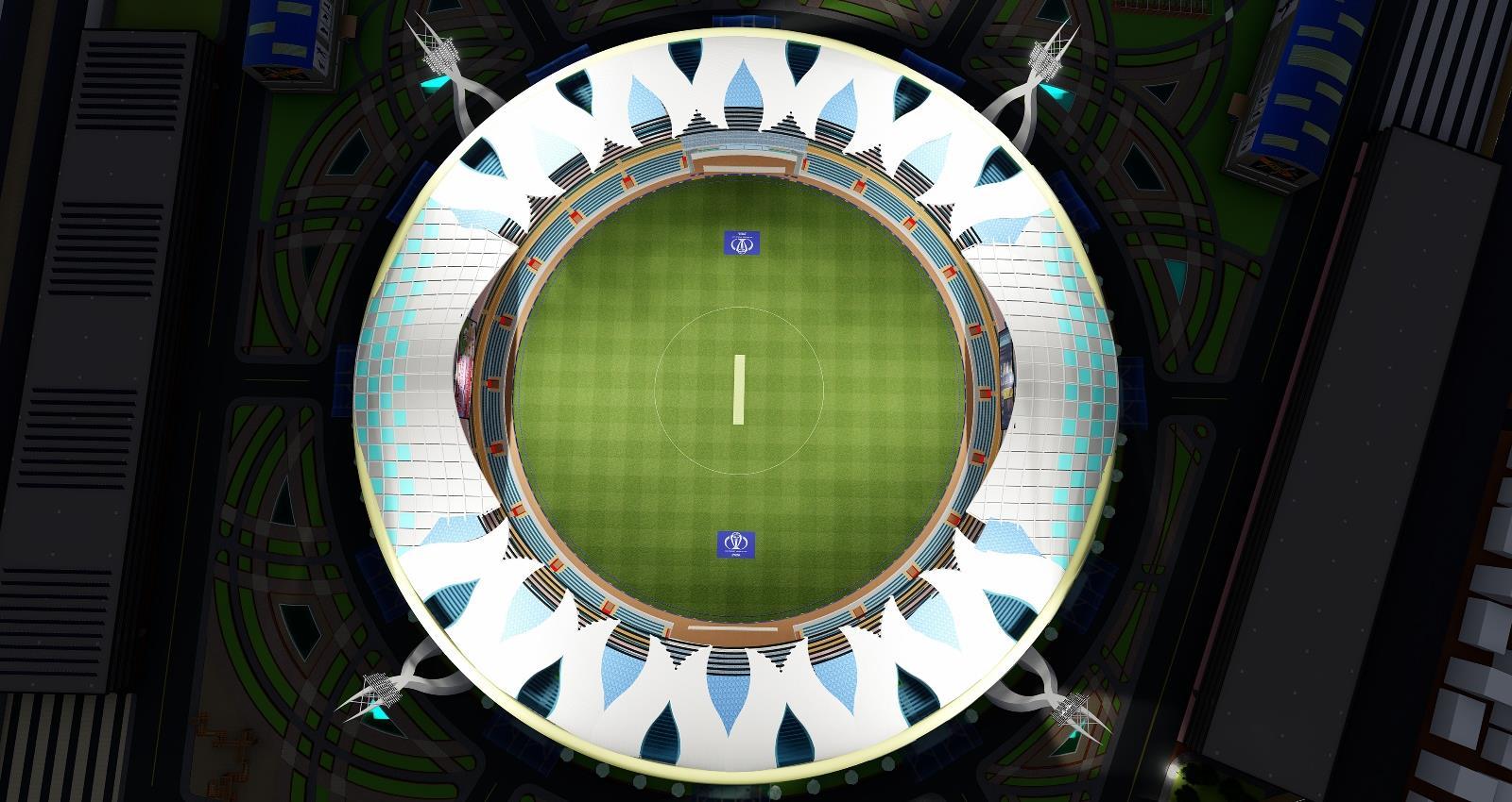
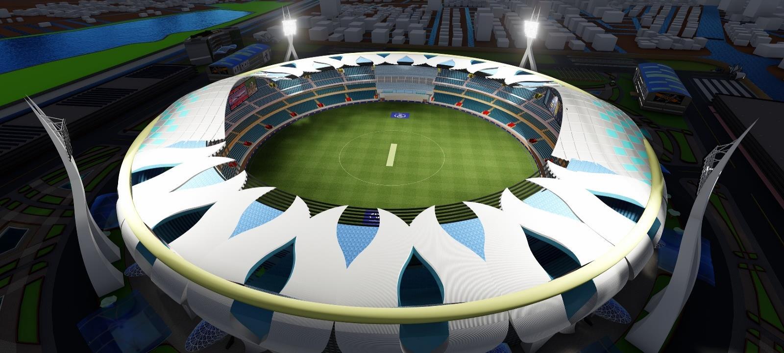
The concept of the stadium is the India Cricket Team logo.
Breaking down the logo outer most sector to derive stadium’s outer core .
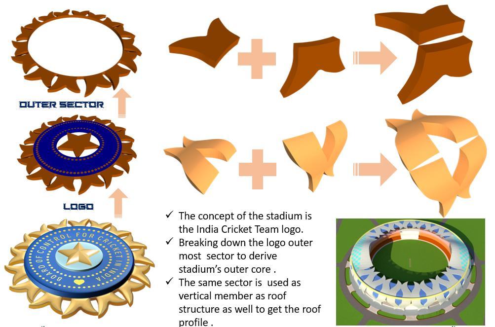
The same sector is used as vertical member as roof structure as well to get the roof profile .
There 18 units of the individual wedges which is used as the vertical members for the stadium forming the outer shell of the stadium .
36 Akhil Manikyam. R 4.6 CONCEPT OF THE STADIUM FORM:-
The advantages of combine planning are
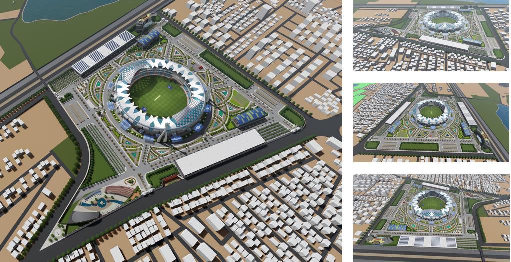
Combine planning consists of two planning which is gird and radial pattern , in which the radial pattern sits inside gird pattern.
The gird pattern becomes the peripheral road of the site.
The 6 radial roads becomes the secondary roads.
The ring road around stadium which acts as fire escape and access to all internal gates .
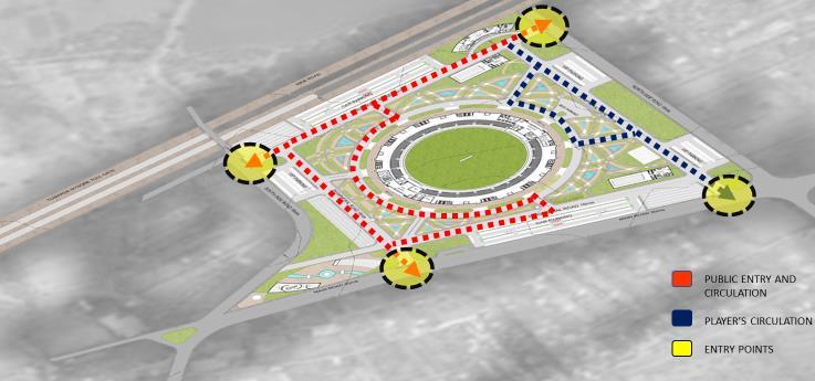
4.9 CIRCULATION PLAN OF THE SITE
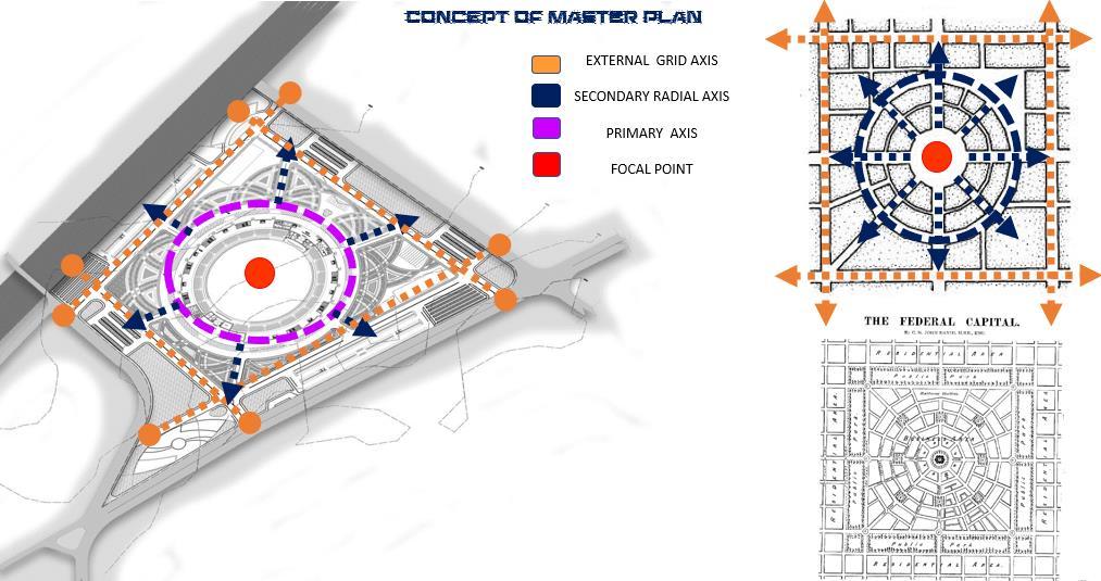
37 Akhil Manikyam. R 4.8 CONCEPT OF PROJECT:-
4.11 SITE PLAN OF STADIUM


38 Akhil Manikyam. R 4.10 MASTER PLAN OF STADIUM
EAST SIDE VIEW NORTH SIDE VIEW WEST SIDE VIEW
39 Akhil Manikyam. R
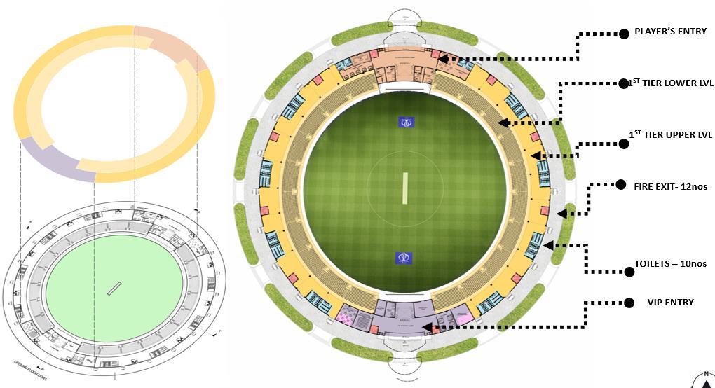
4.12 GROUND FLOOR PLAN OF STADIUM
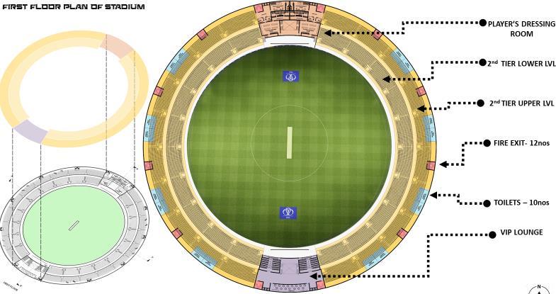
4.13 FIRST FLOOR PLAN OF STADIUM
4.14 SECOND FLOOR PLAN OF STADIUM
4.15 THIRD FLOOR PLAN OF STADIUM
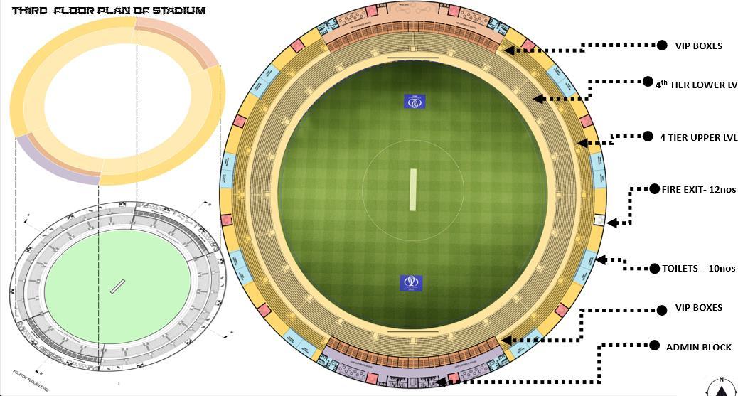
4.16 CALULATIONS
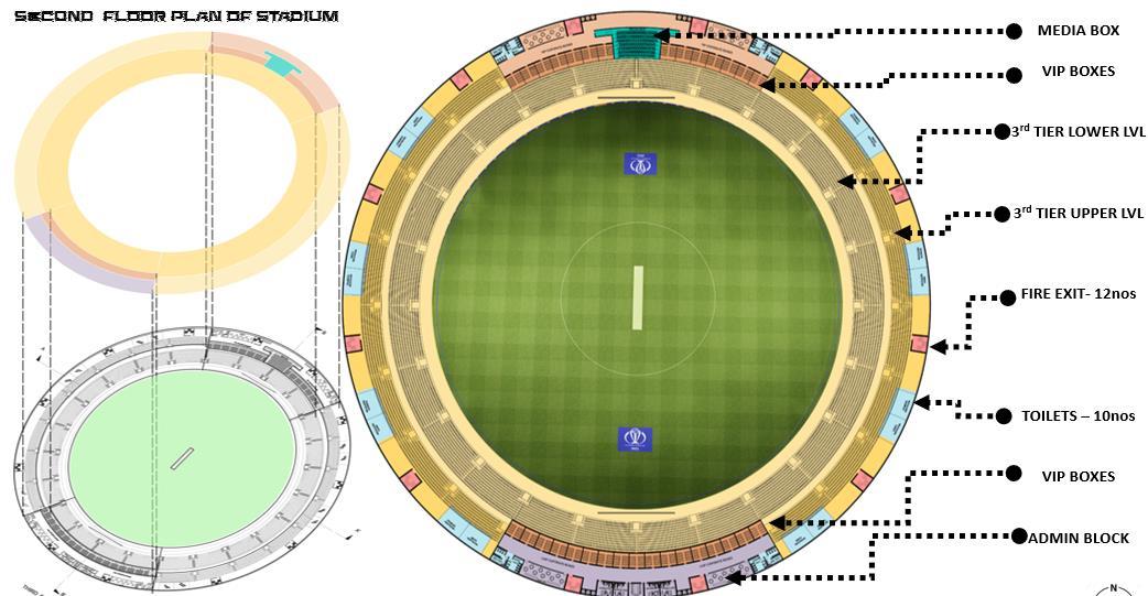
40 Akhil Manikyam. R
Ground floor Tier
Lower sector
1 sector as – 1104 seats
1104 X 10 sectors = 11,040 seats
Higher sector
1 sector as – 760 seats
760 X 20 sectors = 15,200 seats
First Floor Tier
Lower sector
1 sector as – 1104 seats
1104 X 12 sectors = 13,248 seats
Higher sector
1 sector as – 760 seats
760 X 20 sectors = 15,200 seats
VIP boxes:-
No of boxes – 62 boxes
One box – 32 VIP‘S
62X32 = 1984(2000)VIP’S
VVIP - 192 seats
Media box :- 132 seats.
Press conference – 72 seats
Players & team management – 50 people
Second Floor Tier
Lower sector
1 sector as – 1104 seats
1104 X 12 sectors = 13,248 seats
Higher sector
1 sector as – 760 seats
760 X 24 sectors = 18,240 seats
Total Ground tier - 26,240
First tier - 28,448
Second tier - 31,488
VIP seats - 1984
Others - 446
Total - 90,000
Akhil Manikyam. R
41
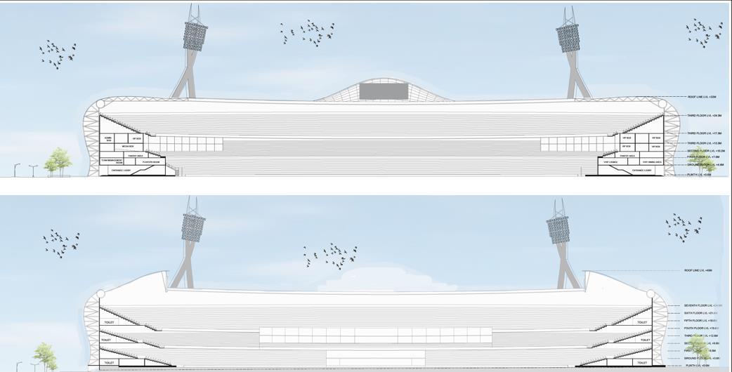
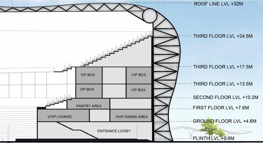
42 Akhil Manikyam. R 4.17 SECTIONS
DETAIL OF SOUTH STAND
SECTION AA’ OF THE STADIUM
SECTION BB’ OF THE STADIUM
DETAIL OF NORTH STAND
FIRE ESCAPE SECTION
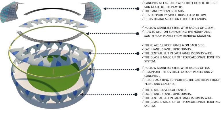
4.18 EXPLODED VIEW OF STADIUM STRUCTURAL SYSTEM

43 Akhil Manikyam. R
4.19 FLOOD LIGHT DETAIL
No of blubs = 80
1 blub = 900watt
Total =7200watt
Total turf area- 20106sqmts
Total lux required - 2000 lux(televised matches)
20106X2000 lux=40212000 lux

40212000/140= 287228 watts
288000 total watts of lights required (1 bulb = 900 watts)
288000/900 = 320 blubs
Total number flood lights tower = 4
320/4=80
one flood light tower as - 80 bubs

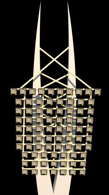
Inclination of the lights is 15˚
Flood light – LED floodlight
900 watt IP65 model

44 Akhil
R
Manikyam.
4.20 FAÇADE DETAILS
The stadium bowl’s unique design, the polycarbonate sheets which are installed across the width of the petal slope toward the edge connecting the polycarbonate with the metal roof, thereby creating a gutter.
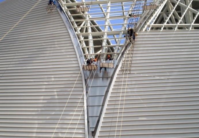
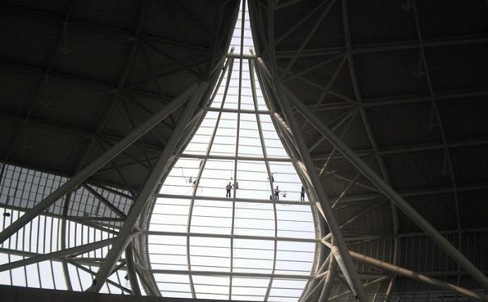
The polycarbonate sheets is laid out in a double curved according to design , each sheet plan is 12mts in length.
This material can withstand wind load capacity 310kg /sqm .

45 Akhil Manikyam. R
Fixing detail of the glass panels of the stadium
Fixing details of panels of the stadium
46
Akhil Manikyam. R
CLUB HOUSE
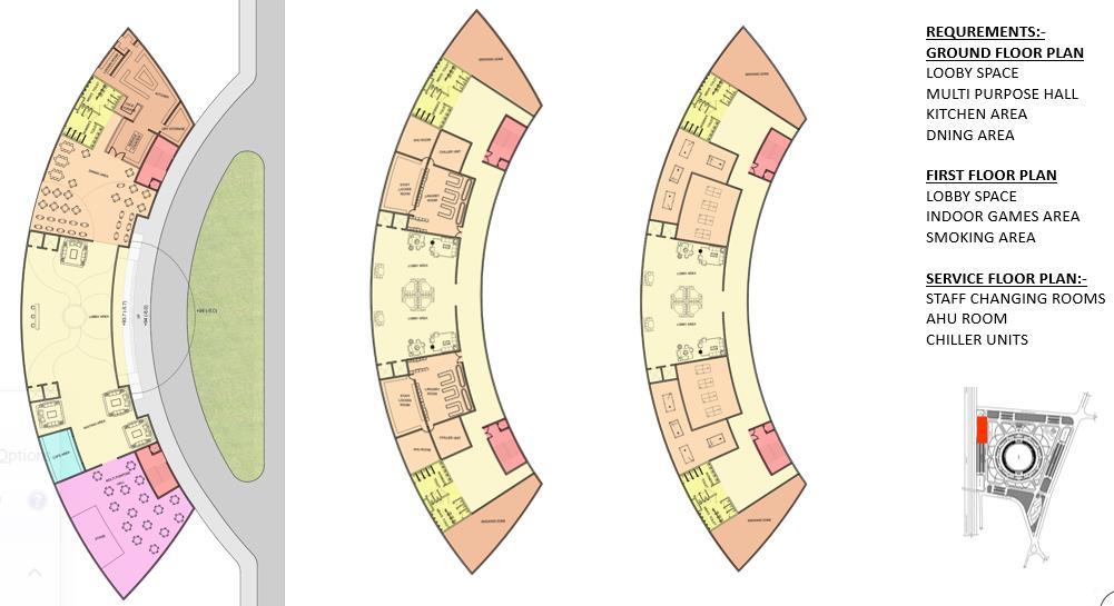
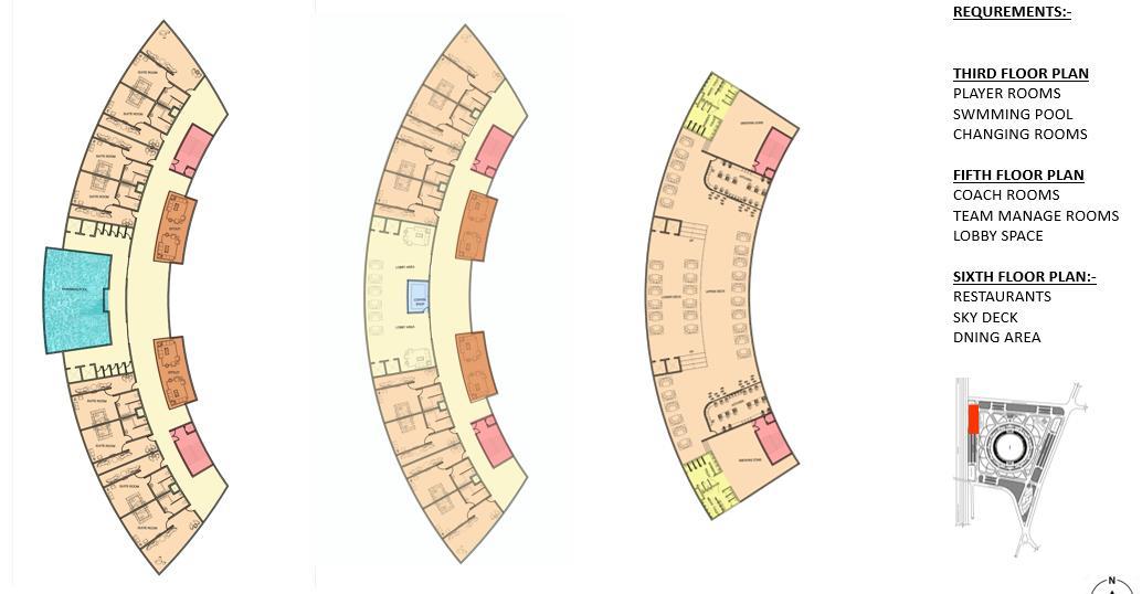
47 Akhil Manikyam. R GROUND FLOOR PLAN FIRST FLOOR PLAN SECOND FLOOR PLAN KEY PLAN THIRD FLOOR PLAN FOURTH FLOOR PLAN FIFTH FLOOR PLAN KEY PLAN
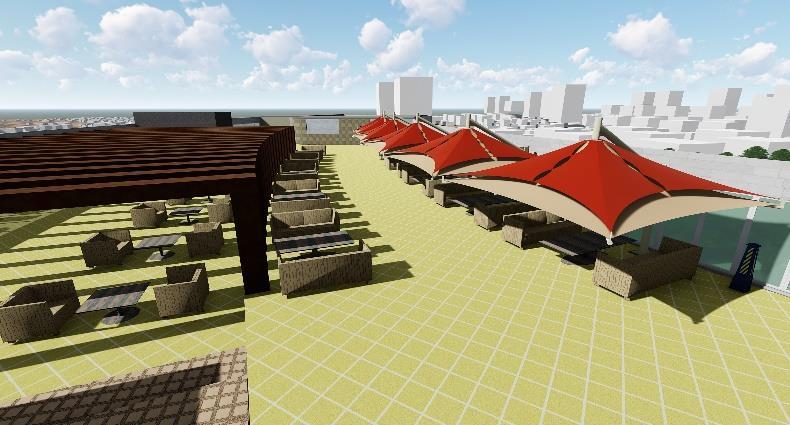
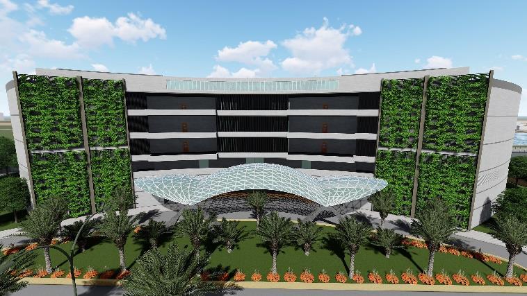
RENDERS OF CLUB HOUSE

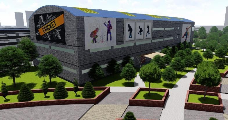
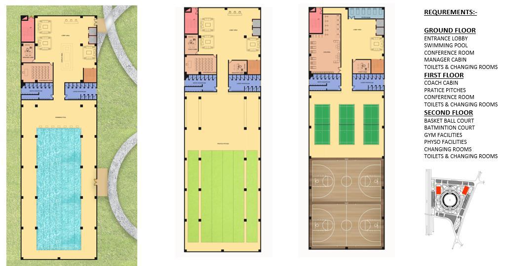
CRICKET ACADEMY
RENEDERS OF CRICKET ACADEMY
48
Manikyam. R
Akhil
FRONT ELEVATION OF CUB HOUSE
SKY DECK OF CLUB HOUSE
SOUTH SIDE VIEW OF CRICKET ACADEMY NORTH SIDE VIEW OF CRICKET ACADEMY
GROUND FLOOR PLAN FIRST FLOOR PLAN SECOND FLOOR PLAN KEY PLAN
SUSTAINABLE STRATEGIES
SOLAR PANEL CALCULATION
TOTAL POWER CONSUMPTION OF SITE :- 3,00,000 WATTS.
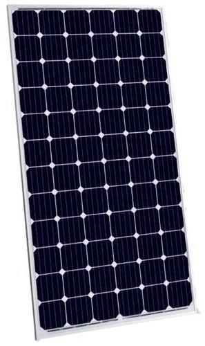
1 SOLAR PANEL = 350 WATTS .
EACH PANEL SIZE :- 1.65X0.99MTS
EACH PANEL CONSISTS OF 60 SOLAR CELLS. 3,00,000/350 = 860 SOLAR PANELS.
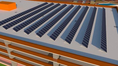
SO THE SOLAR PANEL YARD IS PANEL ON THE PARKING LOT ON THE WEST SIDE OF THE SITE .
THE PARKING LOT IS ABOUT 10,000 SQMTS WHICH IS SUFFICIENT FOR 860 PANELS.
RAINWATER HARVESTING CALCULATION
TOTAL WATER CONSUMPTION STADIUM:12,00,000 LITERS.
CONSUMPTION PER PERSON 10 X 90,000 = 9,00,000 LITERS.
CATCHMENT AREAS ON TOP OF PARKING LOTS:-
ANNUAL RAINFALL AT KENGERI – 33 in CAR PARKING LOT EAST :- 10,000sqm = 7,78,242 LITERS.
BIKE PARKING LOT EAST :- 3,400sqm = 2,64,600 LITERS.
BIKE PARKING LOT WEST :- 4,000sqm = 3,11,297 LITERS.
TOTAL WATER COLLECTED :- = 13,54,139 LITERS
49
Akhil Manikyam. R
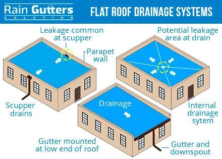
Figure 61 rainwater harvesting source: raingutter.com
References
Ben Vickery, G. J. (2007). STADIA . Burlington, MA: British Library Cataloguing .
BMICPA. (2006). Master plan . Retrieved from BMICPA .
cricket, L. (n.d.). Lord's cricket site plan. Retrieved from lors's cricket stadium.
cricket, m. (n.d.). melbourne cricket stadium site plan. Retrieved from melbourne cricket stadium. fielding position of cricketers. (n.d.). Retrieved from aitiusdictory.com.
floodlights . (2006). Retrieved from cricket stadium floodlights.
stadium, h. c. (2005, 03 13). Rajiv Gandhi cricket stadium. Retrieved from hyderbad cricket stadium. wikipedia. (2001, 01 15). history of cricket. Retrieved from Wikipedia.
Works Cited
Ben Vickery, G. J. (2007). STADIA . Burlington, MA: British Library Cataloguing .
BMICPA. (2006). Master plan . Retrieved from BMICPA .
cricket, L. (n.d.). Lord's cricket site plan. Retrieved from lors's cricket stadium.
cricket, m. (n.d.). melbourne cricket stadium site plan. Retrieved from melbourne cricket stadium. fielding position of cricketers. (n.d.). Retrieved from aitiusdictory.com. floodlights . (2006). Retrieved from cricket stadium floodlights.
stadium, h. c. (2005, 03 13). Rajiv Gandhi cricket stadium. Retrieved from hyderbad cricket stadium. wikipedia. (2001, 01 15). history of cricket. Retrieved from Wikipedia.
Akhil Manikyam. R
50


