11 minute read
Teules "Shingles" Pavilion
TEULES “Shingles” PAVILION
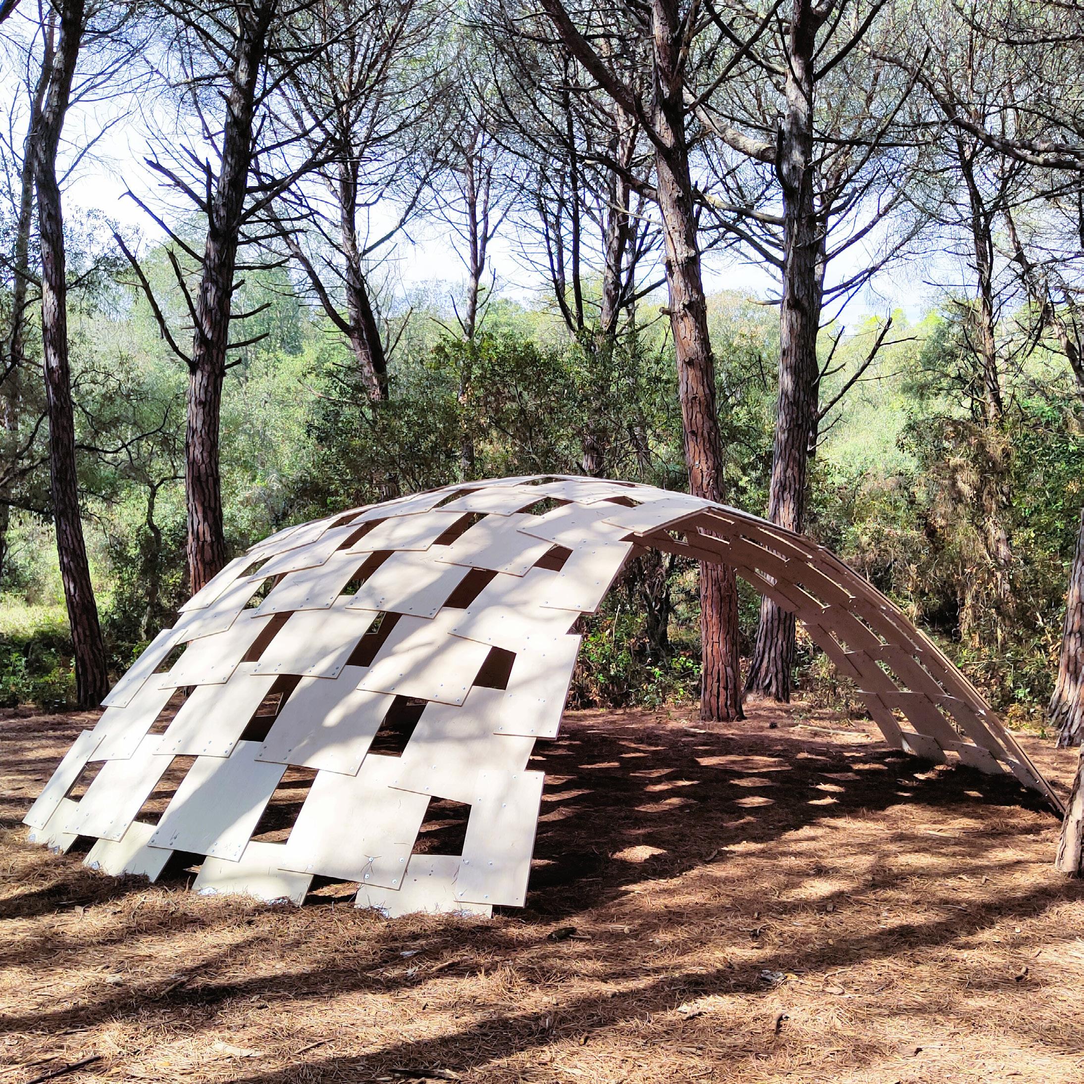
The Teules “shingles” Pavilion is a topology based doubly curved building system, based on active-bending of a single plate element. The pavilion was erected at the Art & Gavarres festival in Girona, Spain. The system used is an extension of R. Buckminster Fuller’s plydome research, with an algorithm to improve the overlaps, the digital analyses of the structural models, and to evaluate the panel sizes and bending of the panels. This was a material driven design where the properties of the material helped determine the radius of curvature as well as the bending of the panels.
Project Type // Masters Final Thesis and Research
Client // Art & Gavarres, Girona, Spain
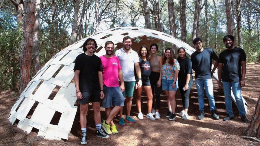
Team // Anna Nasrallah, Arshita Ravindranathan, Bindhuja Reddy, Mariona Rodriguez, Nayib Perez, Shylesh Kumar
Tutors // Enrique Soriano, Gerard Bertomeu, Pep Tornabell, Marc Serra, Anna Bauer, Julien Lienhard
Geodesic. Active-bending. Versatile.
https://www.artigavarres.cat/artista.php?id=106
https://www.researchgate.net/publication/374589448_Self-Strutted_Shingles_Shell_Design_and_Construction
Objective // Design
Aim
The core of this research is to explore the distribution of a set of boards so that a plydome structure with an overlap of two boards on each corner could be built. With the use of advanced computational tools, optimization algorithms were developed in order to find the most suitable overlaps. The project was further developed by experimenting the same system and methodology on different topologies to prove and validate the approach. Lastly, the results of different approaches, including the constructed one, were compared and evaluated giving an insight on the best performance.
Site
The shell, spanning around 6m, was designed in an academic framework during the Master in Parametric Design in Architecture at the Universitat Politècnica de Catalunya and constructed for the Art & Gavarres in Girona, Spain, a festival that starts from the idea that art can be a tool that helps us reflect and change our view of the landscape.
Form-finding
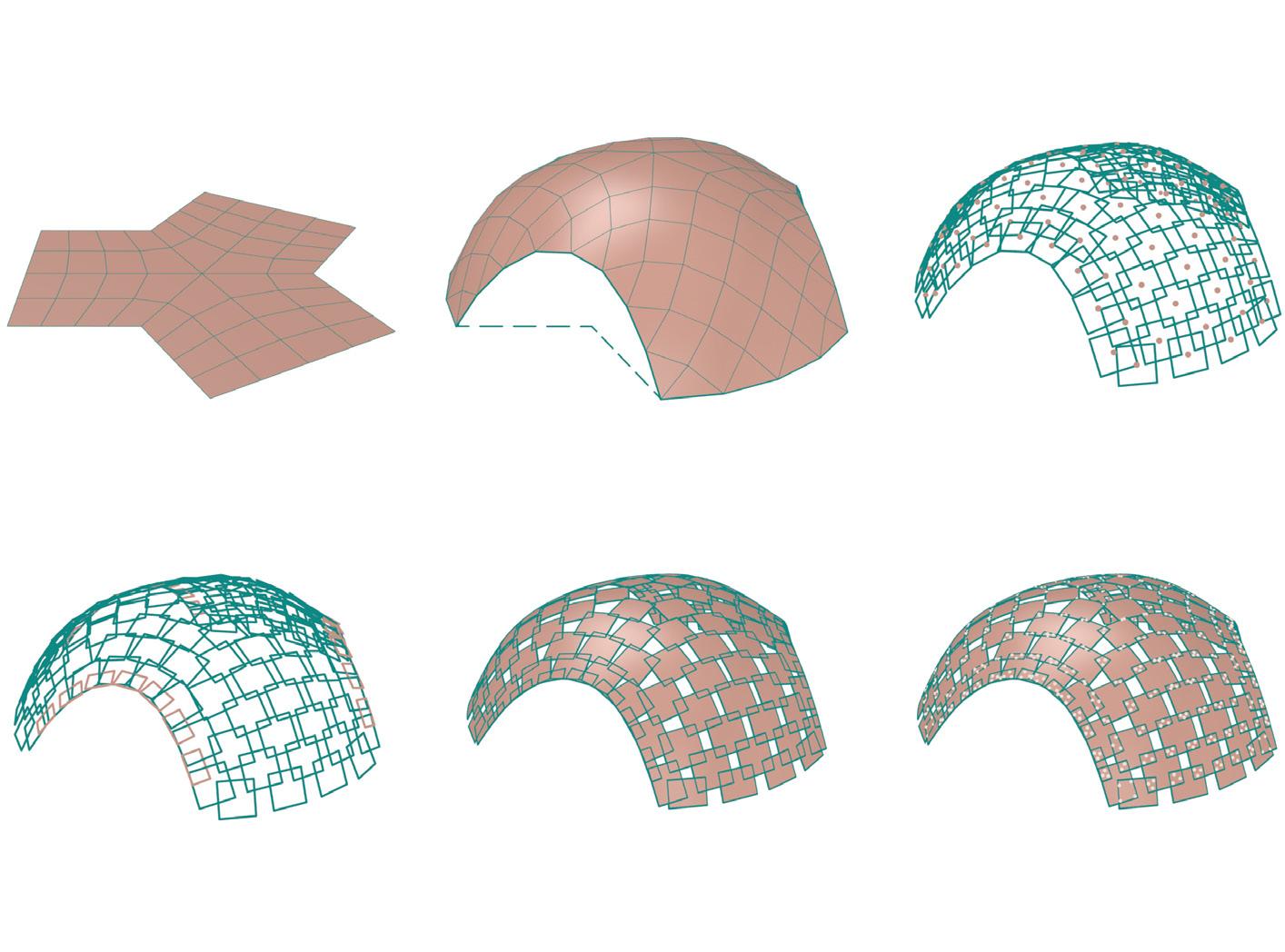
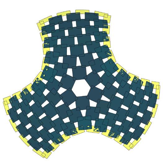
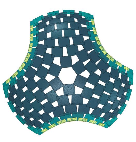
A base coarse mesh was made spanning 7m, which was dynamically relaxed to achieve the desired form. The mesh diagonalized to extract midpoints for each panels, from which the planes were oriented. This was used to construct panels of a particular size (1/8th of plywood board).
The shell was later optimized using the results from the structural analysis done with Karamba3d and Kiwi, which were two plug-ins used for structural analysis. One of the main optimizations was to reduce the deformation or breakage at the entrances, hence the arched openings were stiffened using doubly-layered rectangular panels (1/16th of plywood board). The form of the shell was dynamically relaxed in three consecutive steps using Kangaroo as seen above in the diagram.
site view // pavilion at Art & Gavarres festival
coarse mesh as base
relaxation 02 // optimizing the overlaps of the panels as per similar areas and equal lengths
relaxation 01 // form-finding and diagonalizing the mesh
relaxation 03 // projecting the planar panels onto the initial mesh to get bent panels
constructing the panels for the shell (1/8th of plywood board)
final form of the dome
Model 1 // perspective view 1
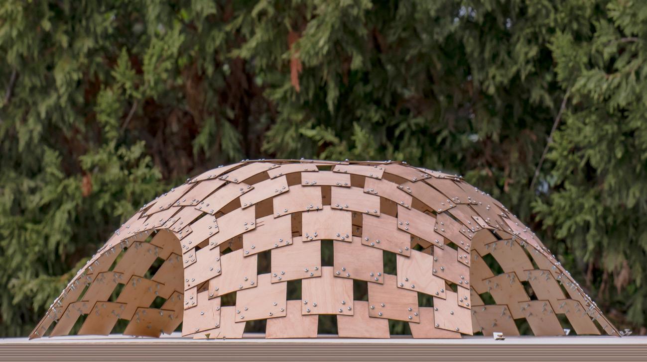
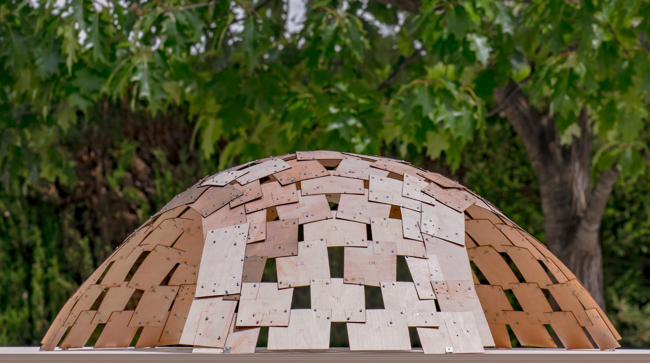
Model 2 // perspective view 2
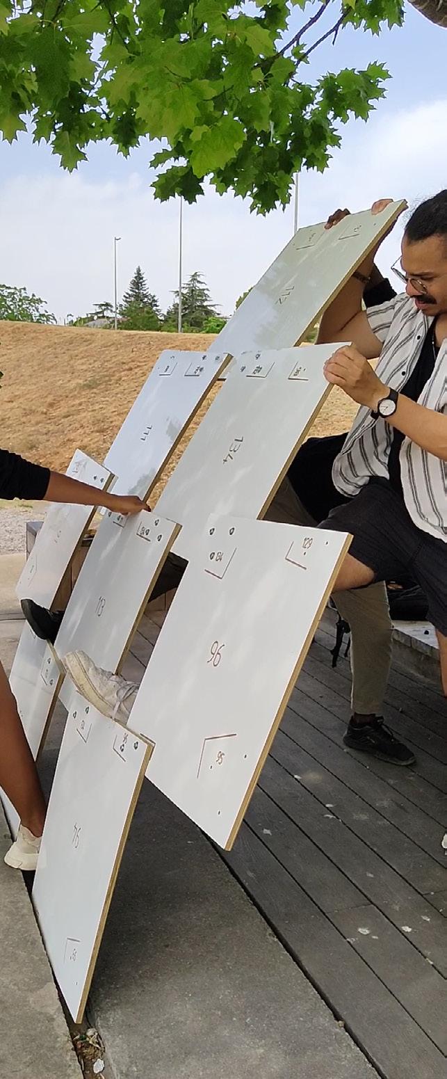
Mockup // bending test and curvature 3
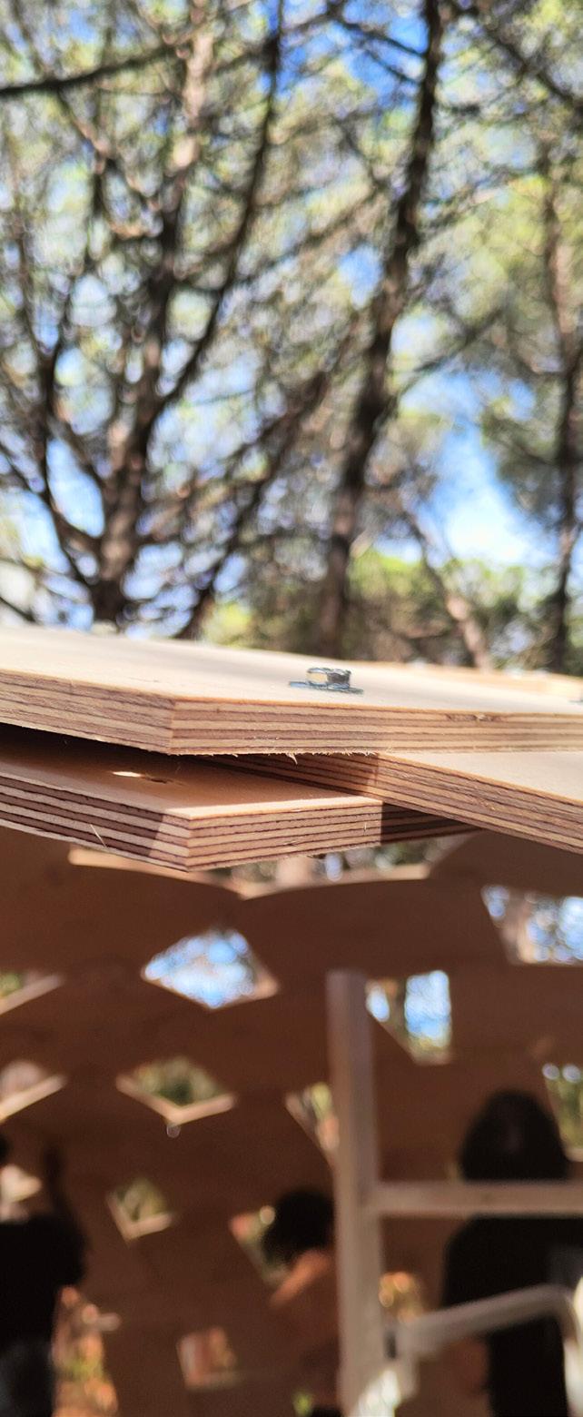
Joinery // M6 zinc bolts-washers-nuts 4
photography credits © Andrés Flajszer
mesh B // 135 panels // prototype mesh
138 panels //
COMPARATIVE ANALYSIS FOR TEULES PAVILION OF METRICS
mesh C // 53 panels
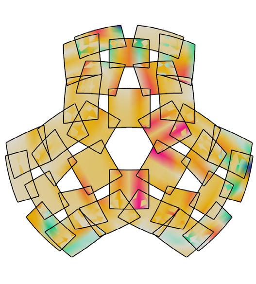
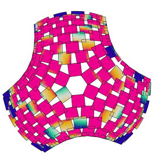
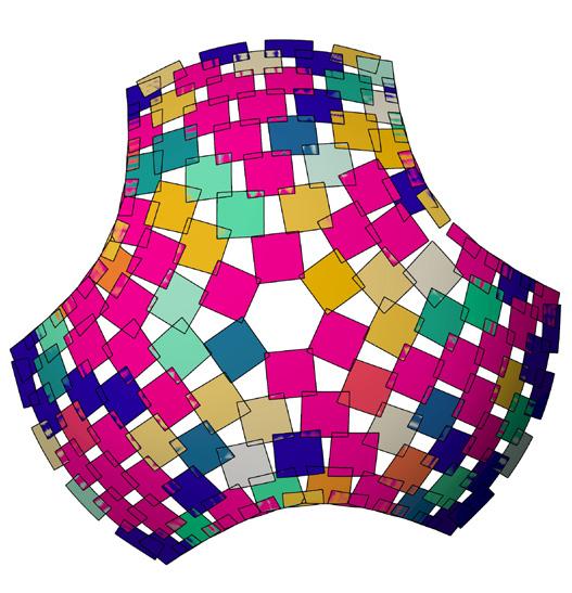
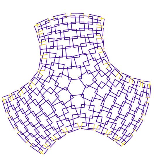
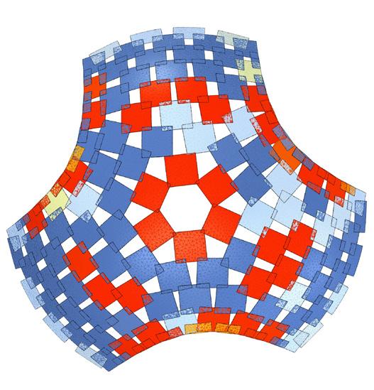
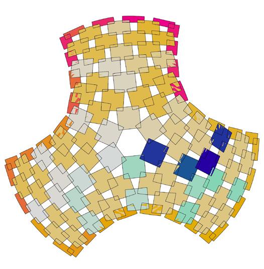
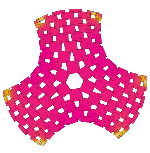
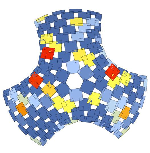
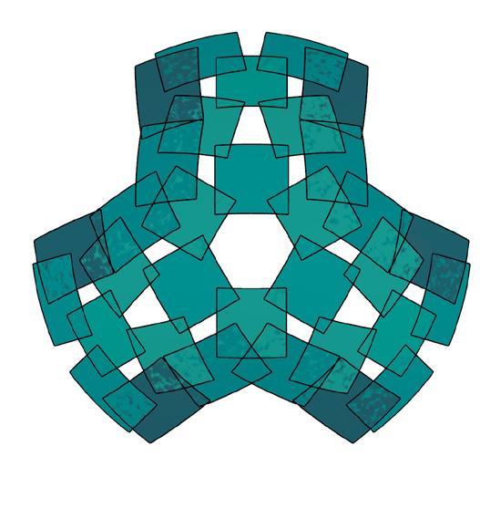
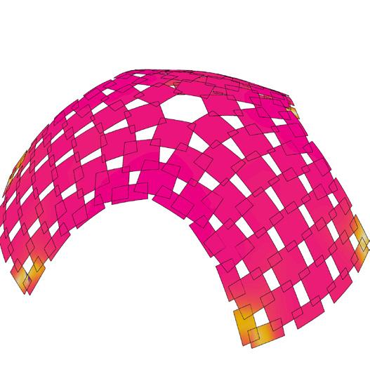
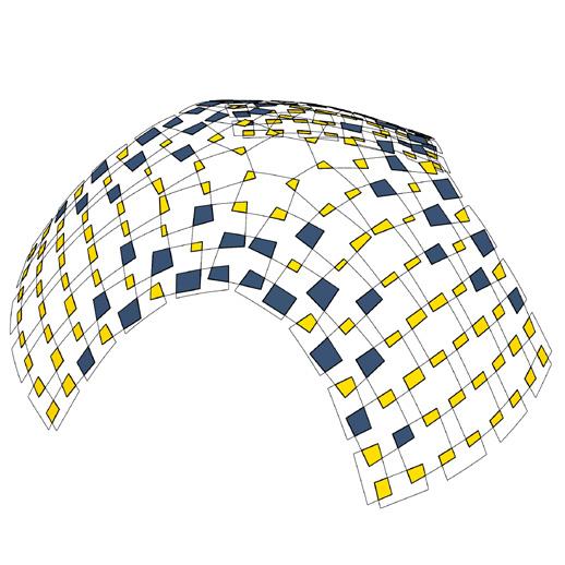
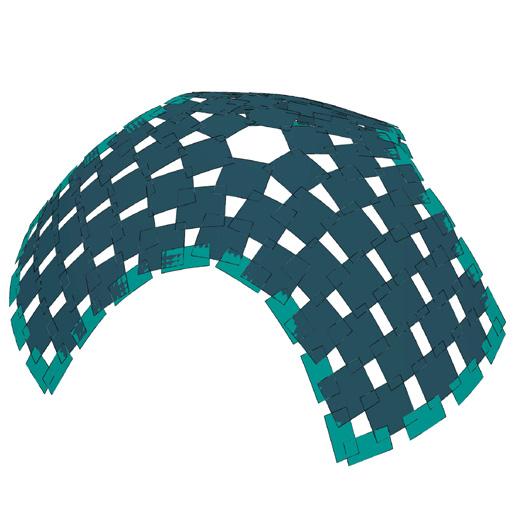
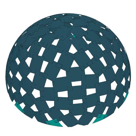
metric 1 // face area
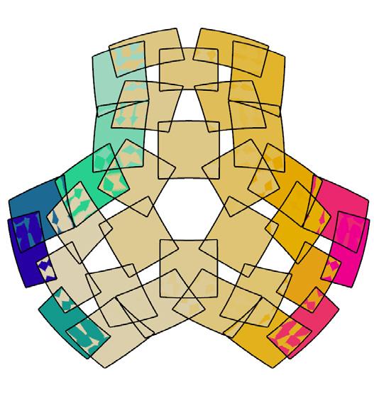
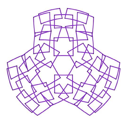
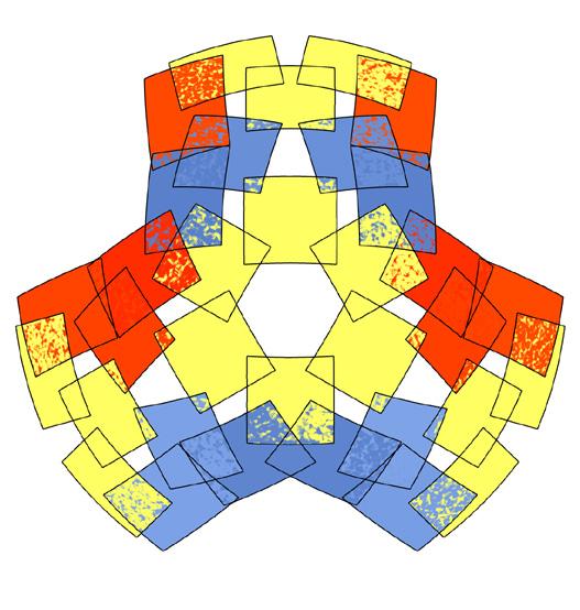
metric 2 // aspect ratio
metric 3 // edge lengths
The radius of curvature is calculated using J. Lienhard’s formula for bending, The radius is inversely proportional to thickness.
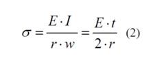
metric 5 // allowable thickness per panels
Day 01 // site setting 1
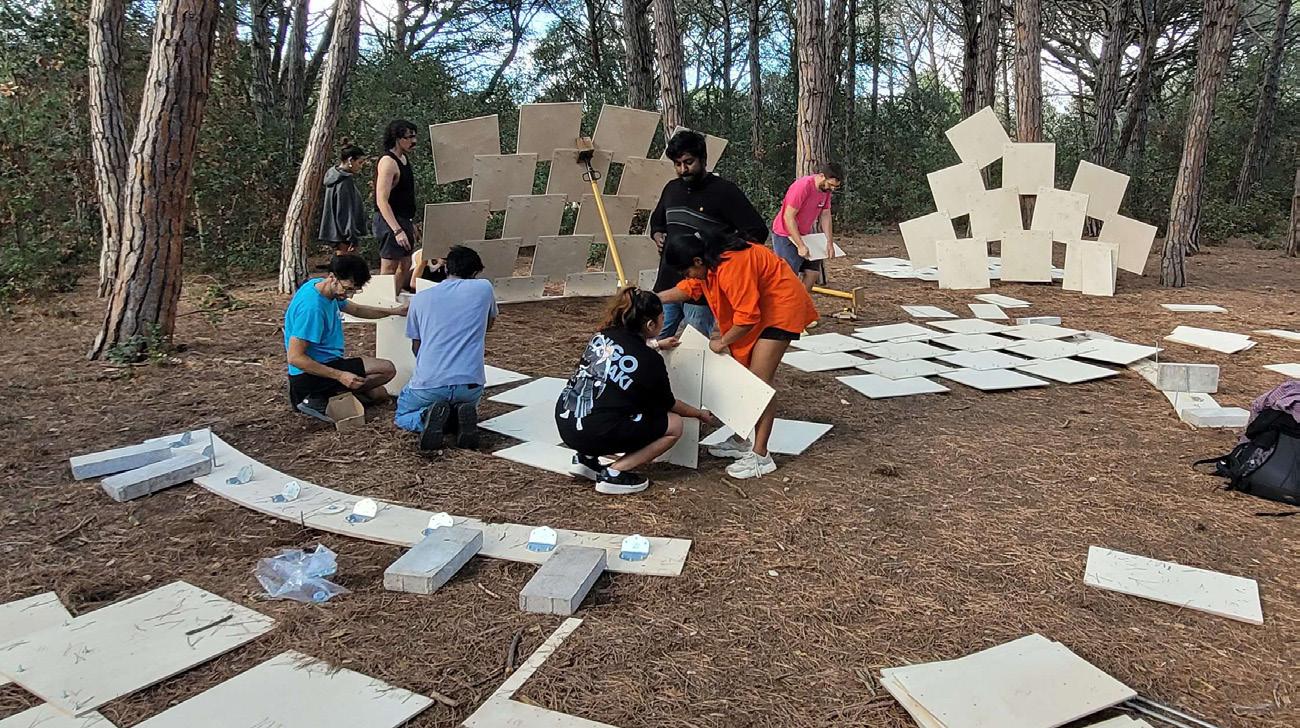
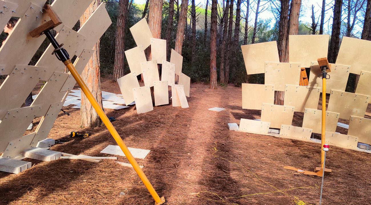
Day 01 // anchoring the legs 2
Day 02 // stiffening arched openings 3
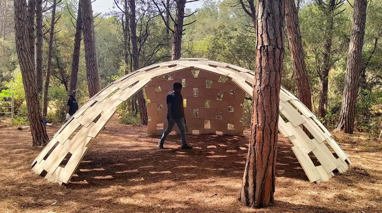
View // completed self-strutted shell 4
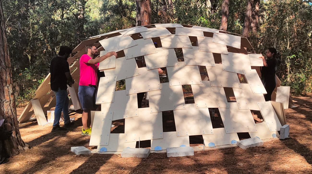
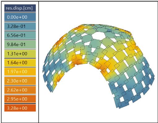
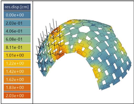
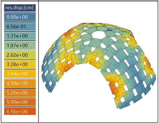
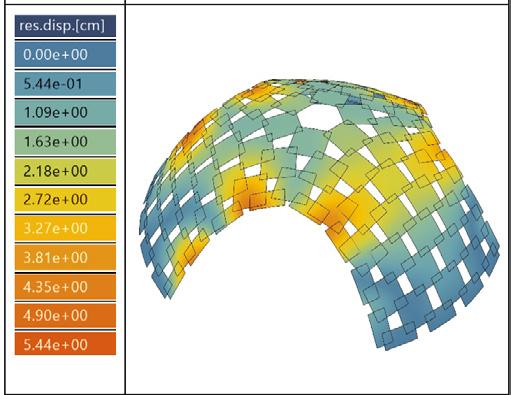
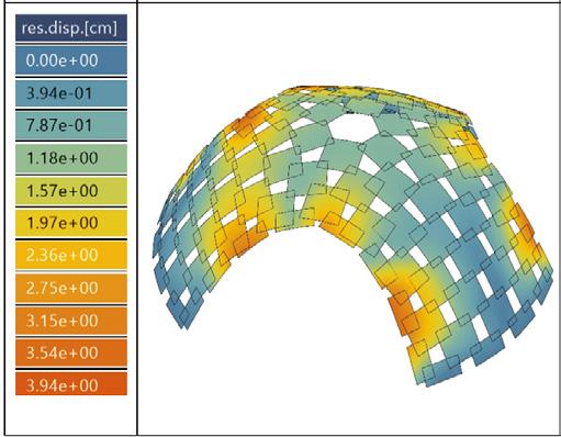
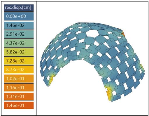
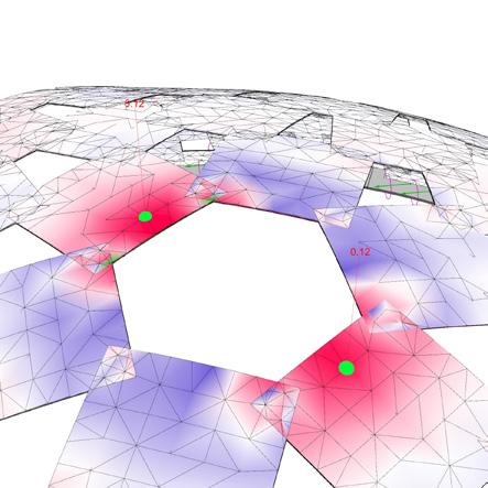
vertical displacements // various load cases
Structural Analysis
Brief
The structural analysis of the pavilion was done in Karamba 3d and Kiwi, structural plug-ins for Grasshopper. The different analysis done were:
1. Displacement under different load types (deflection)
2. Utilization of elements
3. Stresses across panels
4. Cross-section optimization
5. Displacements with prestressing The factors and co-efficients were taken from the eurocodes, UNEEN 14080:2013 and CTE DB SE-M. Along with this material properties were considered for accuracy. A part of the leg was built as mockup to test the bending and radius of curvature.
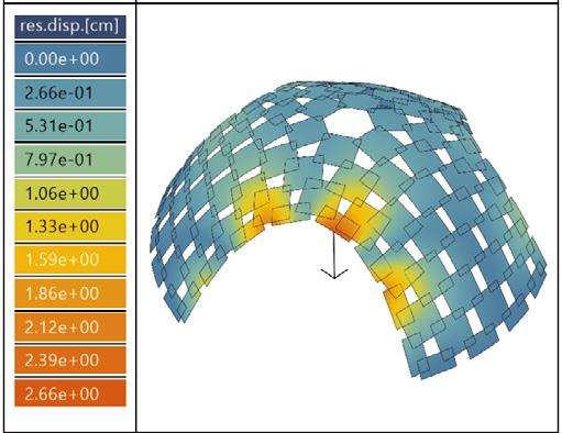
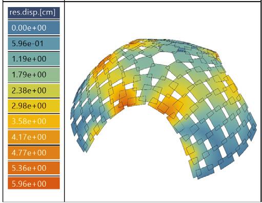
Material
Panels // 9mm thick birch plywood Base // 9mm thick birch plywood Connections // Stainless Steel plates
Spirafix (anchors)
The plywood properties were taken from the Handbook of Finnish Plywood by UPM, namely, Modulus of Elasticity, E = 11395 N/mm² Modulus of Rigidity, G = 620 N/mm² Tension, fc = 40.8 N/mm² Compression, ft = -28.3 N/mm² Density, p = 680 kg/m³ **Tensile strength utilization at 60%
Load and Combinations
The load types and their combinations were taken as per the European and Spanish guidelines.
The different load types are: Dead load or gravity, G Wind loads, Wx and Wy (Zone A with base velocity of 5m/s) Point loads, P (1 kN) Asymmetrical loads, As Simulated loads, P1-P2-P3 (varying conditions and loads)
The load combinations included Ultimate Limit State (ULS) and Serviceability Limit State (SLS) combinations.
Results
Total no.of panels: 138 (after stiffners)
No.of anchor points: 24 (base)
No.of joints: 620 (bolts)
Mass: 247.73 kg
Maximum displacement: 4.576 cm
Maximum stresses: 1.60 kN/cm²
Range of displacements as per load combinations: 0.108cm To 6.559cm (maximum limits)
load testing // stationary-dynamic loading
load combination, ULS3x max. displacement // 3.28cm
load combination, ULS3y max. displacement // 3.94cm
load combination, ULS2x max. displacement // 5.44cm
load combination, ULS2y max. displacement // 6.56cm
point load, P max. displacement // 2.66cm
load combination, ULS1 max. displacement // 0.146cm
asymmetrical loads, As max. displacement // 2.03cm
load combination, ULS_EV max. displacement // 5.96cm
Model A // Analysis from Karamba
• prestressing not considered
• results of verticcal displacements taken for comparison between analysis done with Karamba and Kiwi
• utilization of elements, principal stresses, equivalent stresses calculated additionally
• cross-section optimization using material properties, utilization of elements and maximum displacement
Model B // Analysis from Kiwi3d
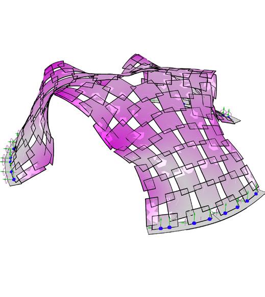
• prestressing considered
• prestressing helps evaluate true vertical displacements to its maximum limits
• maximum deformation observed mainly in panels along the arched entrances
• bending capacity, shear capacity and axial capacity calculated using various load conditions
• vonMises stress, S < bending strength of material, B
gravity or dead load, G max. displacement // 0.08cm
point load, P max. displacement // 1.84cm
envelope load, ULS_EV max. displacement // 4.18cm
gravity or dead load, G max. displacement // 0.28cm
structural performance comparison // Karamba and Kiwi
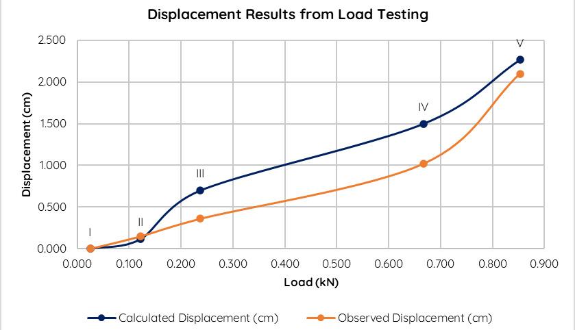
Calculation // Load Testing
Loads
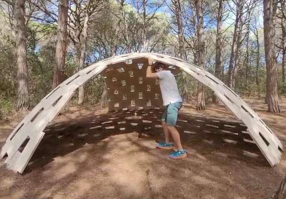
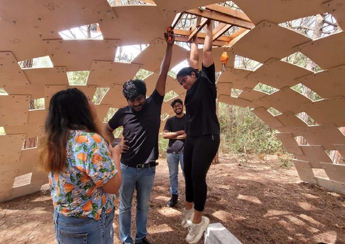
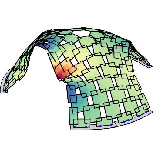
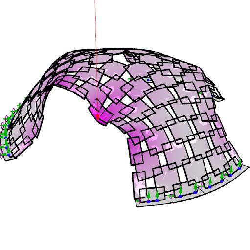
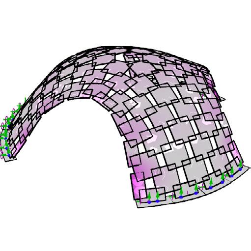
Similar load conditions were simulated to calculate and analyze the results from the structural model done in Karamba. Hence, the loads are placed at approximate positions and distances to get similar results to that of the observed results from the real-scale constructed shell.



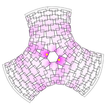
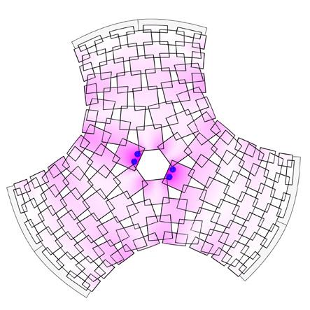
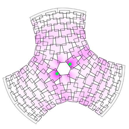

Load conditions
Condition I: Bag of bricks suspended
Condition II: Adult weighing 68kg (distributed evenly along two points)
Condition III: Adult weighing 87kg (even distribution along 4 points)
Observations
On suspension of loads, the vertical displacements are observed to be experienced locally, not globally. Thus preventing collapse of the whole shell These can be observed by bending of panels at the nodes (overlaps). Due to the bolt-washer-nut joints, the whole structure has rigid connections that result in the previously mentioned local failures.
point load, P max. displacement // 2.26cm
envelope load, ULS_EV max. displacement // 4.02cm
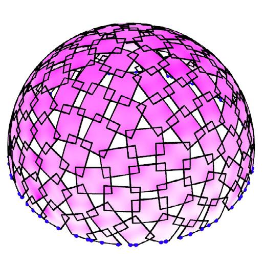
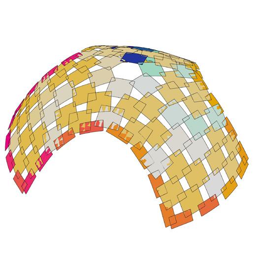
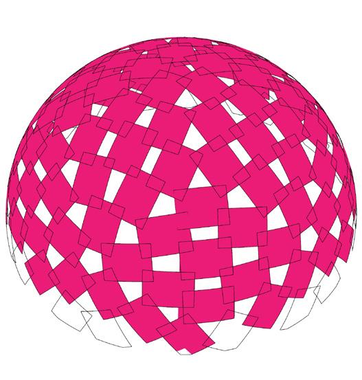
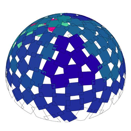
The plydome by Buckminster Fuller is considered as base model to evaluate the curvature and overlaps
model I // Fuller’s Plydome // predecessor
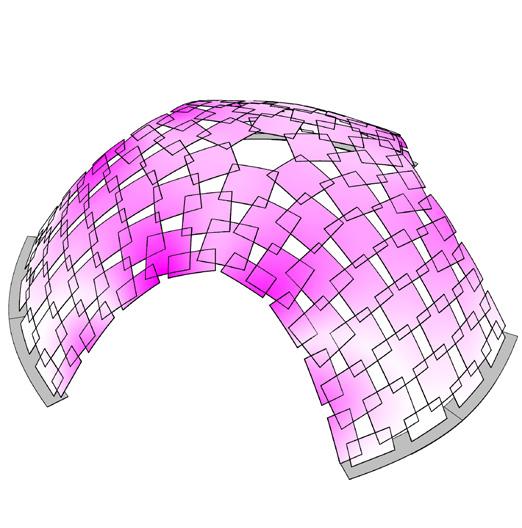
The proposed shell is a variation of its predecessor, where the size of panels were optimized to reduce the material wastage
model II // Teules Pavilion // proposal
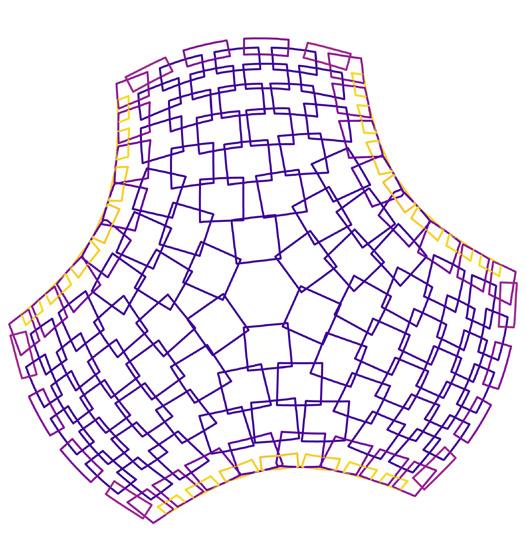
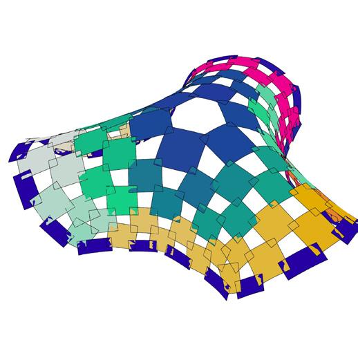
This topological mesh, spanning 8.35m, with a larger height is used to evaluate the efficacy of the algorithm.. It can be observed that the change in subdivisions help determine the panel overlaps.
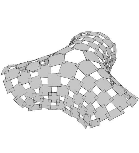
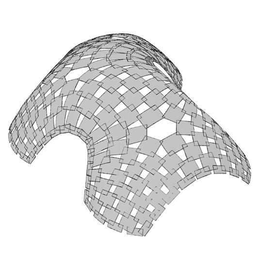
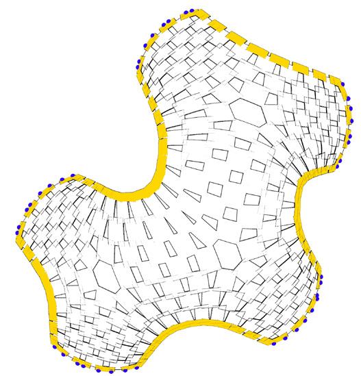
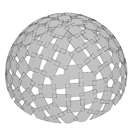
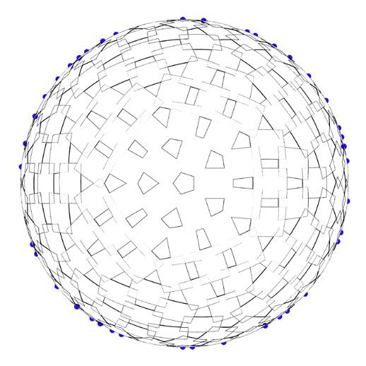
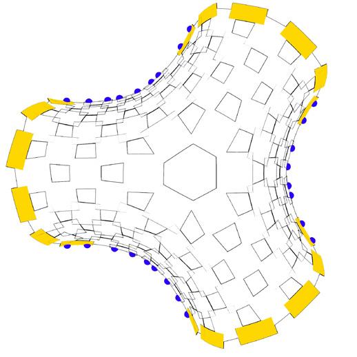
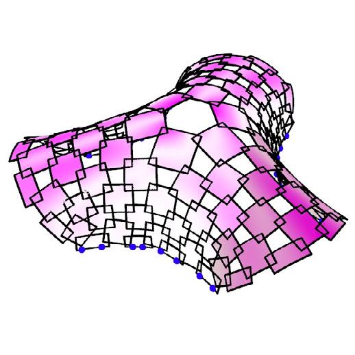
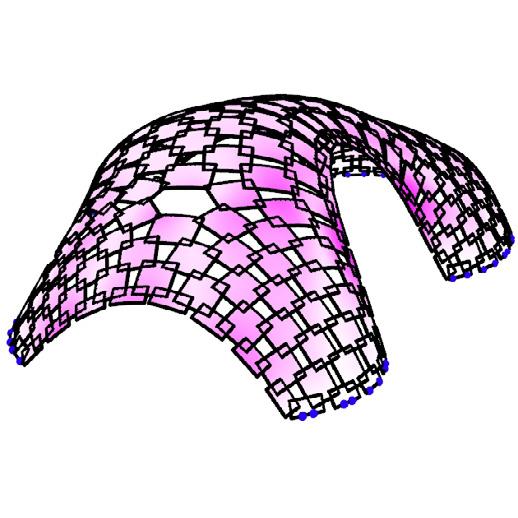
model III // topological mesh 01 with 5 legs
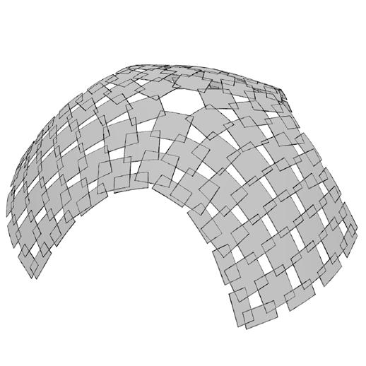
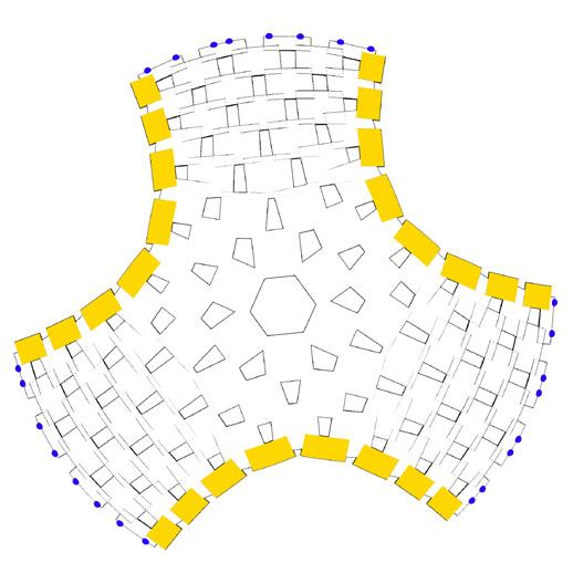
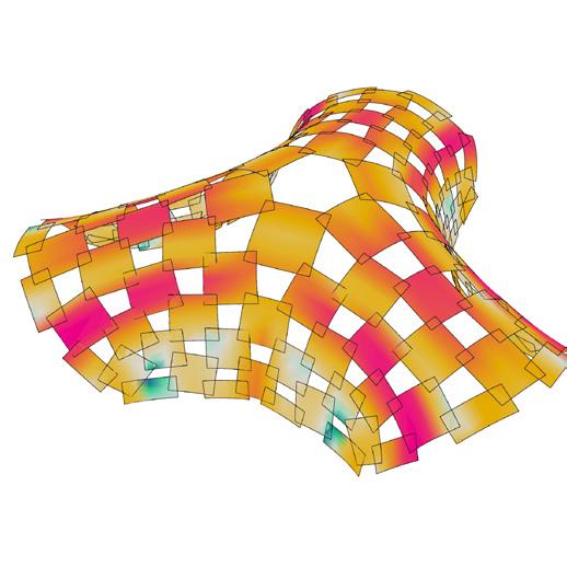
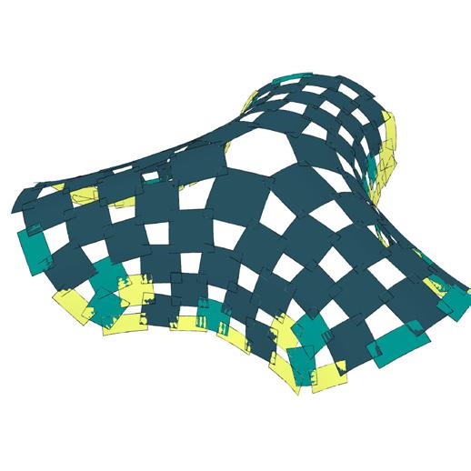
Similar to the above variant, the placement of singularities are evaluated and located at strategic areas to get better overlaps and have same or similar panel sizes. Another factor that aids in better design is the scale factor.
model IV // topological mesh 02 with 3 legs
Graph 01 // span vs mass 1
Graph 02 // displacement vs mass 2
Graph 03 // overlap percentage per panel 3
COMPARATIVE ANALYSIS FOR ALL VARIANTS
metric 4 // allowable thickness metric 3 // radius of curvature
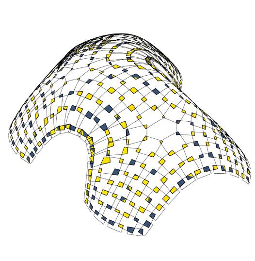
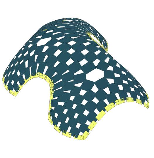
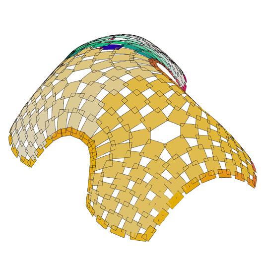
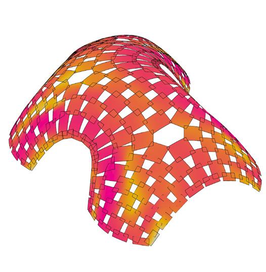
metric 5 // face area


metric 6 // area of overlaps
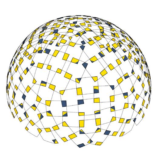
Face area of panels vs % of overlapping areas


