
5 minute read
Tetrápodo

photo credits © Andrés Flajszer
TETRAPODO
Across diverse architectural marvels like the Persepolis Entrance Pavilion in Iran and The Opus in Dubai, planarized quads have played a pivotal role in constructing facade panels, frameworks, gridshells, and more. Extensive study was done, delving into the utilization of quad meshes in construction, dissecting their metrics, geometric properties, and exploring methodologies to integrate algorithms across various structures. This meticulous study was then put into action on the “Tetrapod,” a four-legged form, ensuring optimal outcomes in planarity, surface precision, aspect ratio, linearity, and the fabrication of both convex and concave surfaces within the structure.
Project Type // Digital Fabrication // Rationalization
Team // Adriana M. Chavez, Arshita Ravindranathan, Cristian Cabezas, Miguel Cruz
Planarity. Quadrangular. Linearity.
Methodology
Planar Quadrangular Meshes
A quadrilateral mesh doesn’t inherently possess planar faces and might consist of single or double curved elements, although the latter tend to be more costly.
Advantages of PQ meshes: reduced material usage due to fewer edges, simpler nodes, and easier manufacturing.
Drawbacks: increased expenses for double curved elements, and stability against in-plane forces might require additional diagonal support or face material utilization.
Paramaterization
Mapping the surface onto a planar domain is key for forming a regular quad mesh. Two methods, conformal and harmonic parameterization, enable this. Conformal mapping, preserving surface angles, transforms it onto a planar domain, followed by techniques like Quadtree Decomposition or Circle Packing to construct the quad mesh.
Strategies
Planarity measures the deviation of a panel from a plane. This was gauged through two approaches:
1. distance measurement from three corners to the fourth to create a plane.
2. evaluation of the shortest distance between two diagonal lines.
Various methods explored for planarizing a quad mesh:
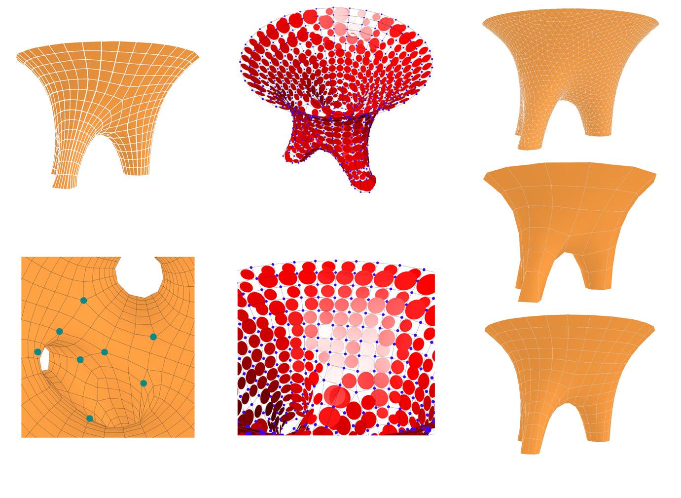
1. Smoothing
2. Simplification
3. Parametrization
4. Optimization (e.g., DR optimization)
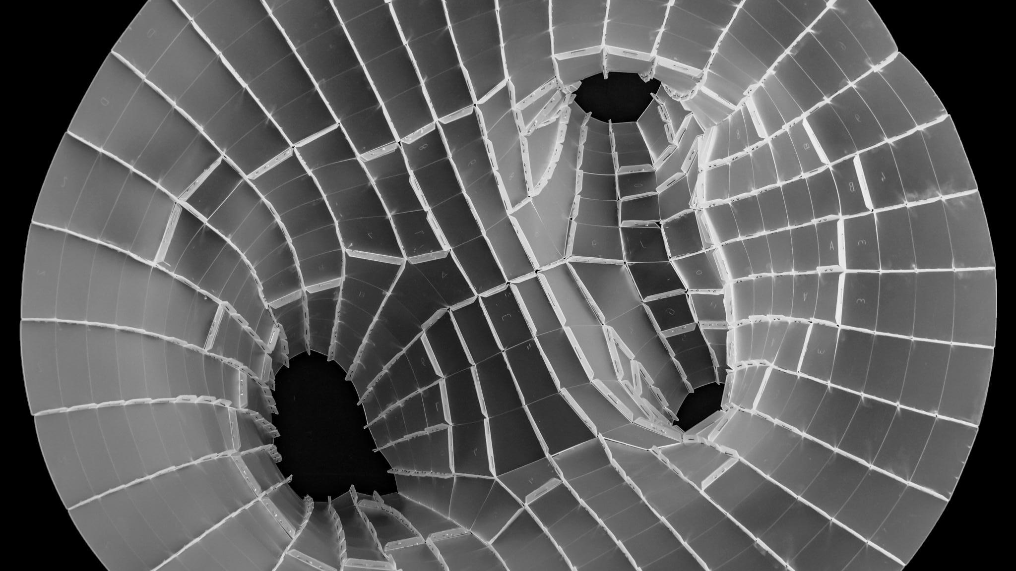
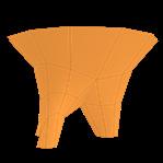
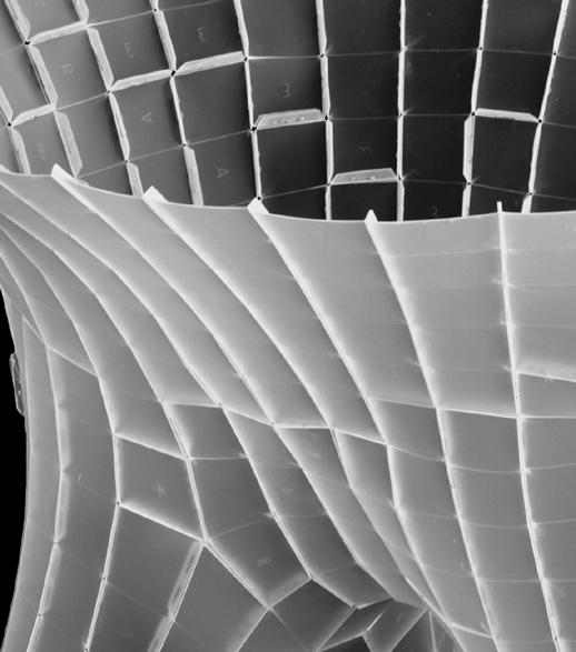
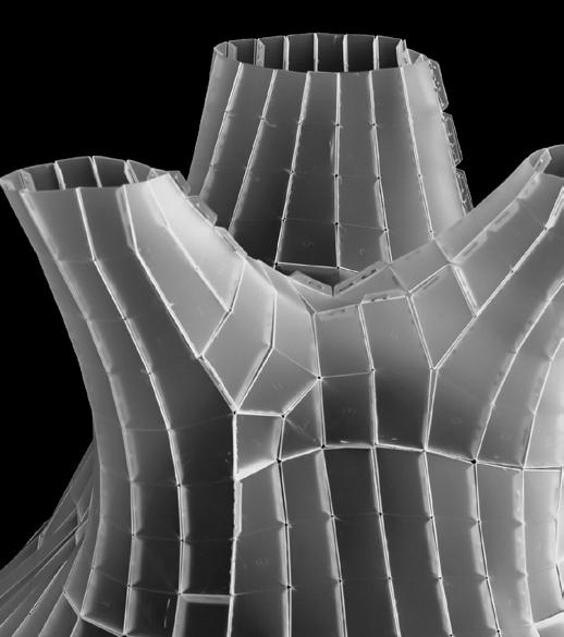
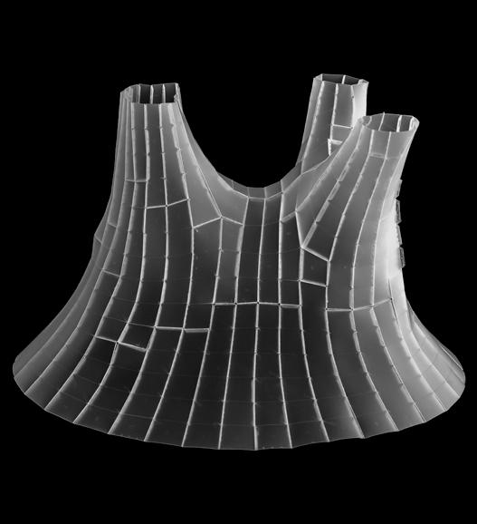
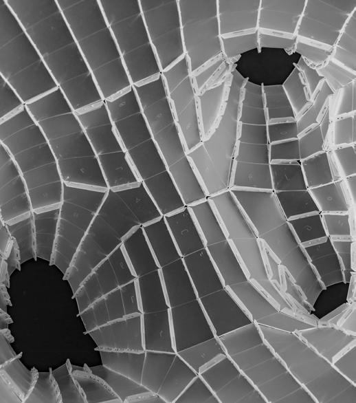
top view // constructed planarized tetrapod with tabs for connection
mesh I // subdividing the coarse quad mesh using catmull clark and C-Sharp
mesh II // triangulated mesh relaxed with a criteria for circle packing
circle packing after using “tangent incircles”and “planarize” goals
mesh III // triangulated mesh converted to a quad mesh and then subdivided for better
Graph 01 // planarity vs no.of faces 1
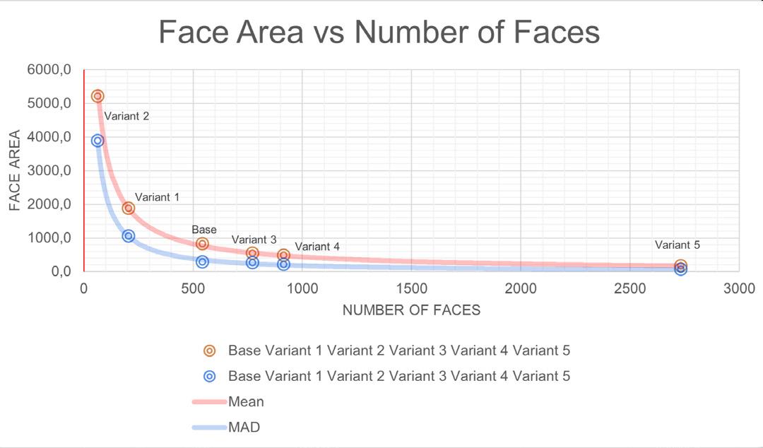
Graph 02 // face area vs no.of faces 2

Graph 03 // surface deviation vs no.of faces 3
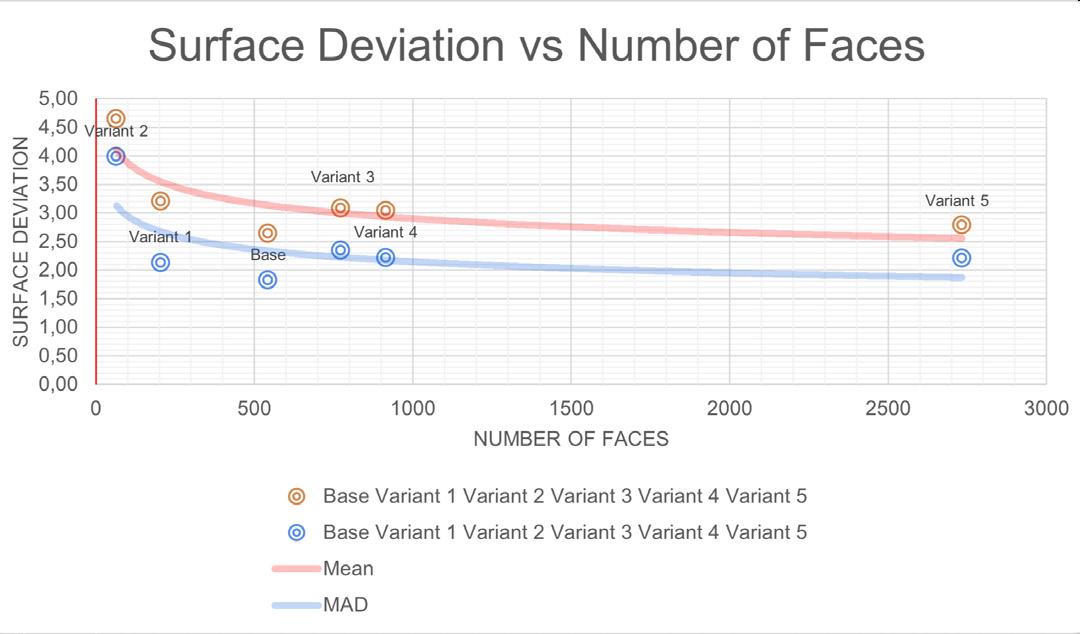
COMPARATIVE ANALYSIS OF MESH VARIANTS WITH REGARD TO FACES
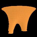


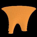
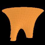
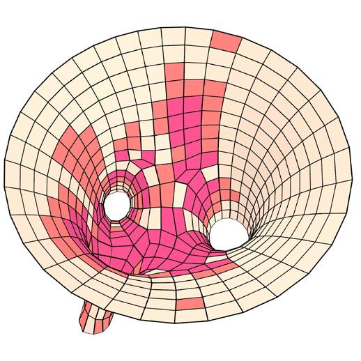
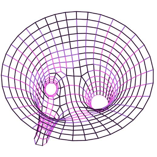
The meshes were planarized using methods described previously where Kangaroo2 solvers were used for relaxation with criteria such as planarize, tangent incircles, smooth mesh and more. The planarity values derived from this is mapped between 0.00 (planar) to 1.00 (non-planar).

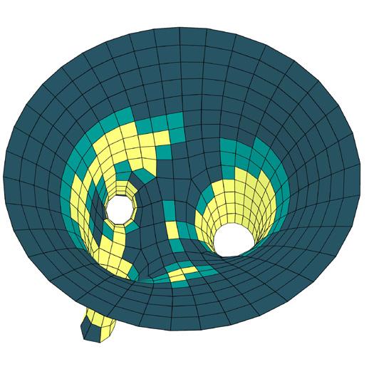
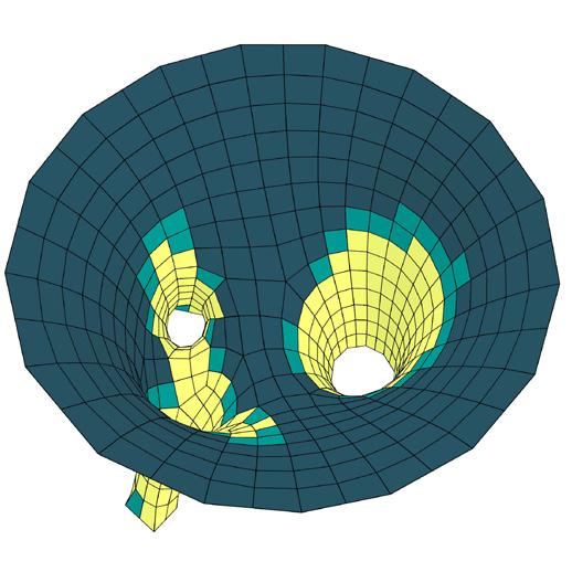
metric I // planarity analysis
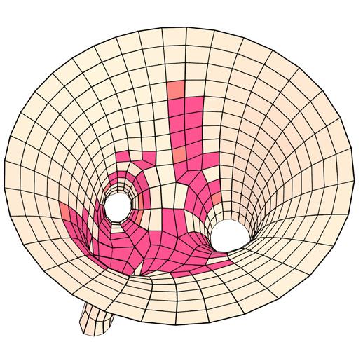
average length // 29.2 mm tolerance // avg. + 10% of avg. (mm)
metric II // edge lengths
This represents the deviation of the final planarized surface from the original surface.

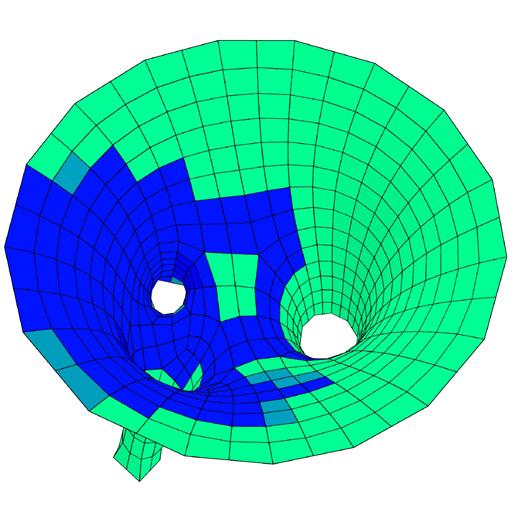
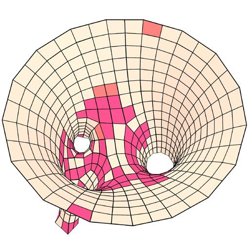

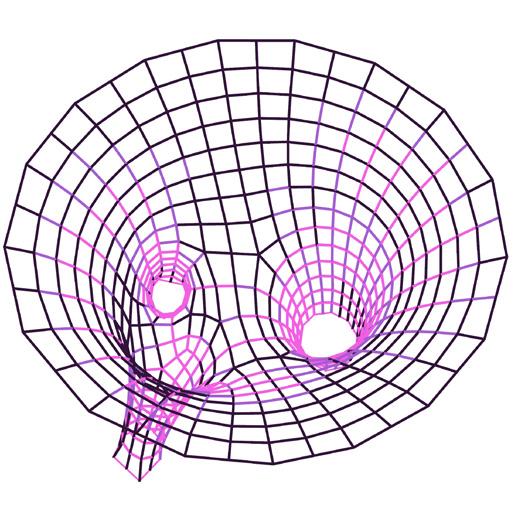


average deviation distance // 237.36 mm tolerance // avg. + 10% of avg. (mm)
metric III // surface deviation
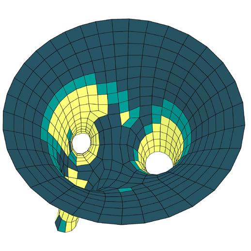
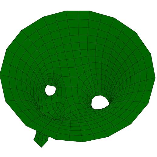
average area // 874 mm tolerance // avg. + 10% of avg. (mm²)
metric IV // face area
average aspect ratio // 1.00 tolerance // avg. + 10% of avg
metric V // aspect ratio
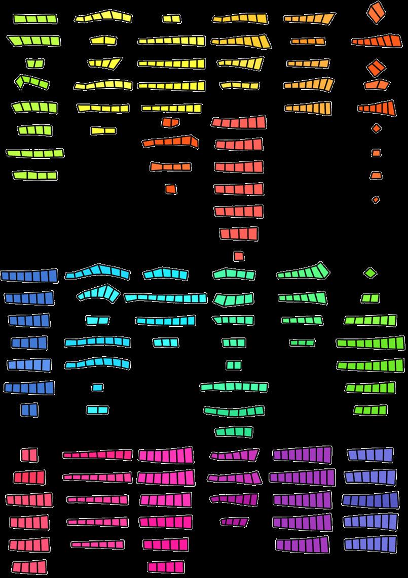
An optimization was done with a plugin “Galapagos”, which aims to minimize the number of clusters. The K-Means clustering is used as Genome, while the Fitness uses the average of the distance between the lines from the curve closest point to Fit Line.
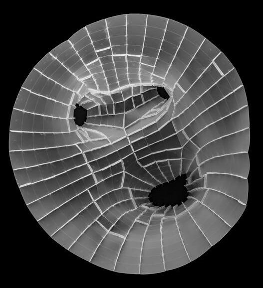
process // optimization & unrolling clusters
optimization 01 // building clusters (without a stream filter)
Clusters of quads were flattened, and tabs were created on the edges to facilitate connection between adjacent clusters.

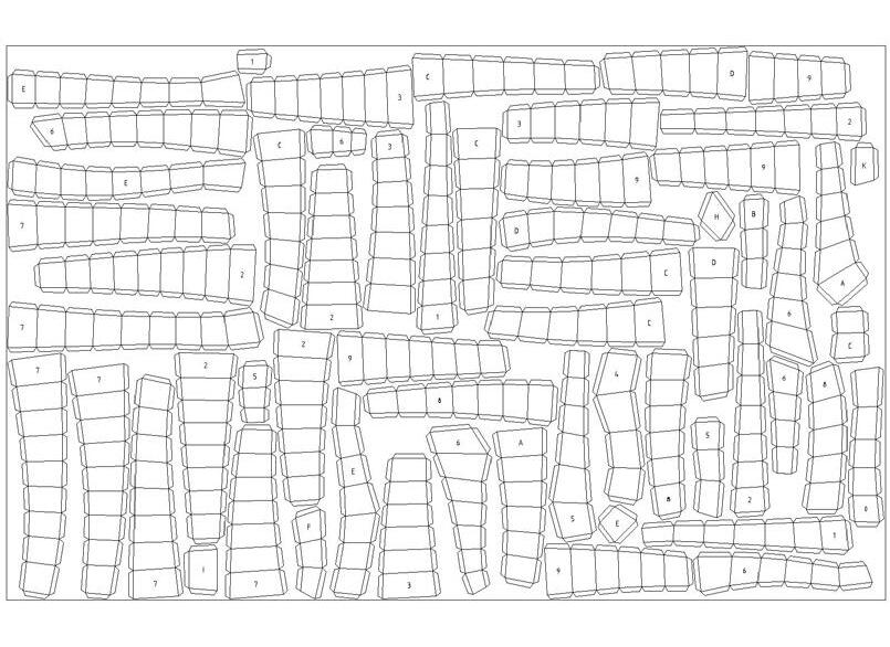

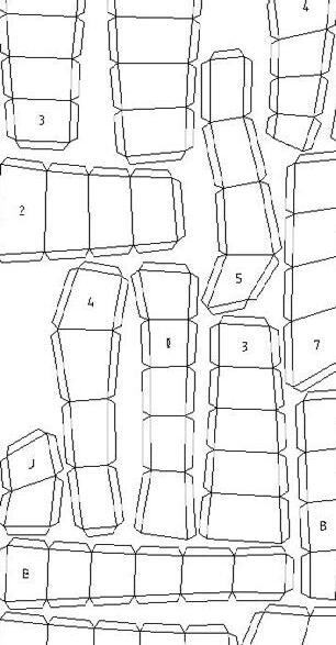
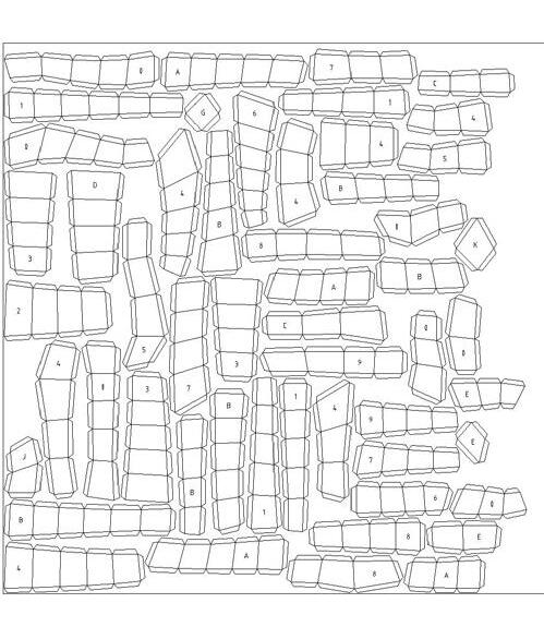
fabrication // clusters sent for lasercut
optimization 02 // orienting all clusters in the same direction (z-axis or vertical)
final result // prototype perspectives
photo credits © Andrés Flajszer


