13 minute read
Houston, we have a problem

from Auto Service Professional - March/April 2013
by EndeavorBusinessMedia-VehicleRepairGroup

Electric fuel pump diagnosis
Houston, we have a problem
Part one of two By Mike Mavrigian
All too often when a no-start condition or hard-start is encountered, some techs may be too quick to automatically blame the electric fuel pump. If you talk to any rebuilder/remanufacturer or new parts manufacturer’s warranty folks, they’ll tell you that in the majority of return cases, the fuel pump that was returned as faulty was in fact problem-free. Before you jump the gun and swap out a fuel pump, consider performing a simple voltage drop test to check the circuits that are responsible for pump activation. Do we have fuel?
We realize how basic this sounds, but before performing any type of diagnosis related to a suspected fuel pump problem, verify that there’s fuel in the vehicle tank. Whether you’re dealing with a gas or diesel engine, she’s not going to f re unless the pump has available fuel to suck out of the tank and push forward to the injectors. You may laugh at this reminder, but if we didn’t mention this, I’m sure we’d get letters criticizing us for not including this caution.
Electric fuel pumps on electronically controlled fuel injection systems need to produce enough “high” pressure to allow the injectors to produce a suff cient spray of atomized fuel into the intake path (or into the combustion chamber in a directinjection system). Fuel pressure is typically in the 35 to 45 psi range. The electric fuel pump needs to be able to produce more pressure and f ow than is needed, with pressure being controlled within the engine’s requirement range by the pressure
A non-delivery or weak delivery fuel problem shouldn’t automatically be blamed on the fuel pump. In far too many instances, fuel pumps are replaced needlessly.

regulator. With the engine at idle (low engine speed), the regulator allows more fuel to be returned to the tank in order to keep the fuel pressure from building beyond what the engine needs at the time. At higher engine speeds, the amount of fuel returned to the tank is reduced.
What else can stop the pump?
Aside from insuff cient power signal or poor ground issues that can affect pump operation, late model pumps incorporate previously separate components into the fuel pump assembly. This includes the pump, f lter, fuel level sensor and in some cases the pressure regulator. In many of these conf gurations, the signal produced by the crankshaft position sensor and monitored by the ECM will kill the pump when/if the engine dies/stalls out.
If the vehicle was involved in a collision, impact sensors can kill the pump signal, as well as signals generated through air bag systems.
Citing various diesel applications as an example, the diesel engine may feature an external high pressure oiling system that’s responsible for injector operation. If the high pressure oil pump (or related pump components) wear or fail, insuff cient (or no) high pressure oil will be available to run the injectors.
A fuel pressure drop can be caused by a clogged fuel f lter, which can result in the pump drawing vacuum, which leads to fuel aeration (air bubbles in the fuel). A dirty f lter will force the pump to over-work as it tries to push fuel, leading to premature pump failure.
A loss (or drastic reduction) of engine oil pressure can cause fuel pump intermittent or shut-off problems, when the oil pressure sensor signal indicates insuff cient oil pressure (a safety circuit shuts off the pump as a safeguard to help save the engine).
A faulty (stuck) fuel pressure regulator that causes a reduction in fuel pressure can easily be mistaken for a pump problem.
Fuel volume should be in the range of f ve to seven gallons per minute (check with a fuel volume tool).
Other potential causes for fuel pump interruption:
• Inertia switch. Common to many Ford vehicles, an inertia switch shuts off the fuel pump if the switch senses an impact, which could be caused by a collision, a sharp bump at the rear of the vehicle, or even in severe bumpy off-road driving.
Pressing the reset button on the switch will reactivate the pump circuit (the switch is often located in the trunk area). • Airf ow (if intake air ducting is leaking at the throttle plate or other air intake issues are present. • Grounds. Always check for loose, missing or badly rusted tank/pump grounds before wasting a bunch of time with extensive diagnosis. • Poorly installed or faulty theft-deterrent systems, which can kill the signal to the pump. • Faulty ignition switch and/or ignition key. • Faulty or improperly programmed remote-start ignition system.
Voltage drop test
A loss of voltage is caused by the f ow of current through a resistance. An increase in resistance increases voltage drop.
In order to perform a voltage drop test, the fuel pump must be running. Typical voltage drops on both the power and ground side of the circuit should not exceed 0.5V.
Use a quality DVOM with jumper leads
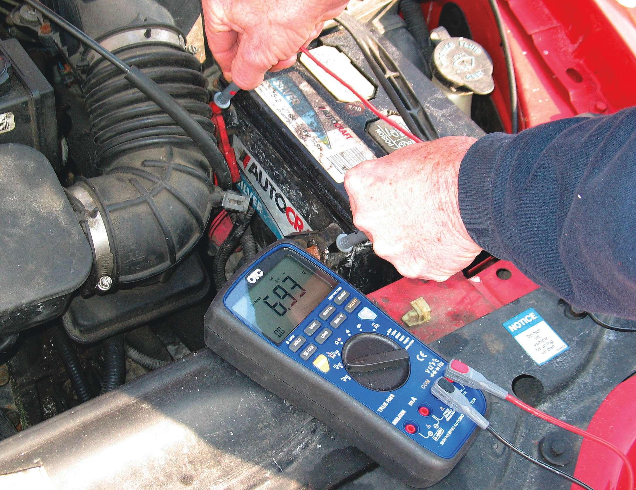
Verify battery status before checking circuits or performing drop tests. Charge or replace the battery as needed.
that are long enough to reach all the way back to the fuel pump.
Perform a voltage drop test on the positive side, with the DVOM red lead to the battery positive post. Turn the DVOM on. Connect the DVOM’s black lead to a red jumper that connects to the pump’s power wire.
You won’t read any drop in voltage until you get current f ow through the pump (again, the pump must be running).
Turn the ignition switch on (to the run position). The pump should run for about two seconds.
With the key on (run position), if, for example, you read a voltage drop of 0.2V, this is acceptable. If you read more than 0.5V, this is unacceptable. If the voltage drop reading is within the acceptable range, this shows that we have a good positive power circuit to the pump, so everything from the battery to the pump is OK.
To check the ground side, connect the DVOM negative lead to the negative battery post, and connect the DVOM positive lead to a long jumper wire that connects to the fuel pump’s ground (the ground at the pump).
It’s best to use a length of straight wire for the long lead, as opposed to a spiral or coiled wire, which may have too much resistance.
Now we need current f ow, so turn the key to the run position (the pump should run for about two seconds). Again, the maximum allowable voltage drop is 0.5V.
Check the ground at the fuel pump. Set the DVOM to DC amperage and select the 10 amp range. Turn the key to the run position. Again, the pump should run for about two seconds.
If the pump draws amperage through the ground circuit, the ground is then verif ed as OK. If the ground circuit does not draw amperage, the problem is likely either the pump’s ground connection or the pump itself.
In this case, drop the tank (if necessary, depending on the model) and perform a continuity test at the ground wire at the pump. If you have continuity, then you know that the pump itself is the problem. Quick check for a no-start condition • Check to see if you hear the electric fuel pump run (with the ignition switch in the run position). • Check the underhood fuel pump fuse. • Check the underhood fuel pump relay.
With the key cycled to the run position, you should hear/feel the relay “click.” • Install a fuel pressure gauge to the fuel injection’s fuel rail (via a Schrader valve port). With the key in the run position, monitor the gauge. Cycle the key on/off several times during this check.
Performing electrical system tests
Courtesy Charley Gipe
Training Operations Lead Engineer, Delphi products & Service Solutions
Fuel delivery problems can often be traced back to problems with the electrical system that prevent the fuel pump from receiving the correct power, which will cause the pump to perform poorly or not at all. Checking for power, ground and understanding how to perform an accurate voltage drop test will be important for correctly diagnosing a suspect fuel delivery system and making the needed repairs.
Although all vehicles provide power and ground to the electric fuel pump, the circuitry used to do this may vary from vehicle to vehicle. Therefore it is important to have a good wiring diagram of the fuel delivery system for the vehicle you are working on in order to determine where electrical connections are located, how current f ows in the circuit and what terminals should be probed when performing diagnostics.
In order to check the electrical system, a DMM (digital multi-meter), ammeter, load tool and a number of test leads will be needed to measure voltage in the system at various points. Probing the electrical connections in the fuel system is necessary when diagnosing it, but care should always be taken so as not to damage the connections. Always probe an electrical connector with the correct test lead to prevent potential damage. Incorrectly probing an electrical connector can result in damage

to the connector, a future failure and a customer comeback.
A number of electrical tests can be performed using the tools mentioned above so let’s review each of these tests and see how they are performed.
Open circuit tests
If a fuel pump is not operating it may be caused by a loss of power or ground to the pump. A simple method of testing for the presence of power and ground to the pump is to remove the vehicle wiring harness from the fuel pump or module, connect a DMM to the power and ground terminals in the vehicle electrical connector, energize the electrical circuit by turning the vehicle key to “ON,” or commanding the fuel pump on with a scan tool and measuring the voltage at the electrical connector. This is referred to as an open circuit test because the voltage value being measured is done with no current f owing in the circuit, while the circuit is electrically “open.”
The equipment you will need to perform this test includes: • A DMM set to the DC volt scale. • Any necessary test leads or electrical terminals to properly probe the electrical connector. • A wiring diagram of the fuel delivery circuit.
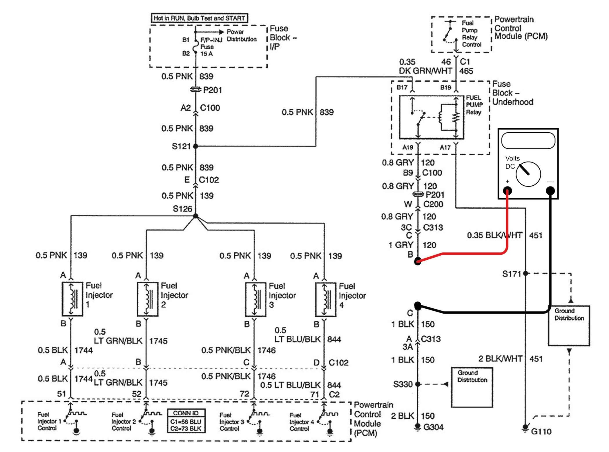
To perform this test: 1. Disconnect the vehicle wiring harness from the fuel pump or fuel module. 2. Using the positive lead of the DMM carefully probe the fuel pump power terminal in the connector (see Figure 1). 3. Using the negative lead of the DMM carefully probe the fuel pump ground terminal in the connector (see Figure 1). 4. Set the DMM so it reads voltage values down to .001 volt. 5. Energize the fuel pump circuit and monitor the DMM voltage. 6. If the circuit is not open the voltage
Figure 1: Shown here is a wiring schematic of the fuel delivery system with the digital multimeter (DMM) connected to measure the open circuit voltage of the fuel delivery circuit.

Circle 117 on Reader Service Card
should climb to approximately 12 volts (battery voltage). 7. If the value noted on the DMM is approximately 0 volts, the circuit is open and should be inspected to locate the open and repaired.
When performing any electrical test on the fuel delivery system it is important to make sure the battery is suff ciently charged and able to provide the necessary power for accurate test results. If needed, test the battery prior to any fuel system test to assure it is charged and in good serviceable condition.
If the voltage noted when the pump circuit was energized is at or near 0 volts there is an open somewhere in the circuit, which is preventing power from f owing to the fuel pump. The open could be on either the power or ground side of the circuit. The location of the open can be determined by testing the circuit with the DMM in the following manner.
Fuel pump ground circuit testing
1. Connect the positive lead of the DMM to a known good voltage supply such as the positive battery terminal of the battery (see Figure 2). 2. Using the negative lead of the DMM carefully probe the fuel pump ground terminal at the connector (see Figure 2). 3. Set the DMM so it reads voltage values down to .001. 4. Note the voltage value on the DMM. 5. If the value noted on the DMM is approximately 12 volts the circuit is not open. 6. If the value noted on the DMM is approximately 0 volts the ground circuit is open and should be inspected to locate the open and repaired. 7. An open in the fuel pump ground circuit can be caused by: • A broken ground wire connection to the vehicle chassis due to rust/ corrosion. • A missing ground wire connection

Figure 2: This illustration depicts the digital multi-meter (DMM) connected to measure the open circuit voltage of the fuel delivery ground circuit.

Circle 119 on Reader Service Card
due to work that was done previously on the vehicle. • A corroded or damaged electrical connection or junction in the ground circuit causing an open.
Fuel pump power circuit testing
1. Connect the negative lead of the
DMM to a known good ground such as the negative battery terminal (see
Figure 3). 2. Using the positive lead of the DMM carefully probe the fuel pump power terminal at the connector (again, see
Figure 3). 3. Set the DMM so it reads voltage values down to 0.001. 4. Energize the fuel pump circuit. 5. Note the voltage value on the DMM. 6. If the value noted on the DMM is approximately 12 volts the circuit is not open. 7. If the value noted on the DMM is approximately 0 volts, the power circuit is open and should be inspected to locate the open and repaired.
An open in the fuel pump power circuit can be caused by:
1. A “blown” or open fuse. 2. A failed fuel pump relay. 3. A vehicle anti-theft or safety system preventing power from being applied to the fuel pump. 4. A damaged electrical connector in the power circuit causing an open. 5. If an open is detected in either the power or ground circuit further testing to isolate the open can be done by using the DMM and wiring diagram to systematically probe the suspect circuit at junction points between the known good connection (either the power or ground) and the vehicle harness electrical connector. When two DMM readings are noted, one at 12 volts and the other at 0 volts, the open exits between these two points in the circuit and the repair work can be focused in this area.
Look for part two in our next issue.
Figure 3: The DMM is connected to measure the open circuit voltage of the fuel delivery ground circuit. Note that the DMM negative is connected to battery negative.