20 minute read
Spark plugs: past and presentP

from Auto Service Professional - March/April 2013
by EndeavorBusinessMedia-VehicleRepairGroup

Fire in the hole!
Spark plugs: past and present
By Bob Weber
Weber is president of Virginia-based Write Stuff. He is an award-winning freelance automotive and technical writer and photographer with over two decades of journalism experience. He is an ASE-certif ed Master Automobile Technician, and has worked on automobiles, trucks and small engines. He is a member of the Society of Automotive Engineers (SAE) and numerous other automotive trade associations. He has worked as an auto service technician, a shop manager and a regional manager for an automotive service franchise operation. F ire in the hole. That, as you know, is how the internal combustion engine works. Mixing fuel and air then igniting it causes a rapid rise in pressure. This is often called an explosion, but in an engine, it is in reality a controlled burn.
Igniting that air/fuel mixture has been a challenge since the f rst engine was built. The challenge continues to f nd better, more durable, more accurate, more timely and more precise ways of burning the fuel.
This is especially true as engineers strive to meet the goals of better fuel economy and reduced emissions. That was of little concern back when the internal

combustion, gasoline engine was born.
The earliest motor vehicle engines used a system called a “hot tube” to provide the ignition. (Prior to the hot tube, slow spinning engines used a slide plate the exposed the cylinder mixture to a f ame, but these typically ran at about 100 rpm). Gottlieb Daimler’s early engines spun up to 600 rpm thanks to the hot tube.
The hot tube was kind of like a glow plug. The heated tube was closed at one end similar to an inverted test tube and was heated by an external f ame. During the compression stroke, some of the air/fuel mixture got pushed into the hot tube where ignition began. Clever, yes, but not very precise. But these were also extremely low compression engines.
Meanwhile, Robert Bosch was f ddling with electricity and inventing something called the magneto. It, too, was a clever device that generated voltage using coils of wire and permanent magnets. The magneto is extremely reliable and durable — so durable and dependable that its magnetos are still used in not only small engines such as lawn mowers, but in small personal airplanes.
At the same time another new device was under development that used the magneto’s electricity to make a spark jump a gap to ignite the mixture for a stationary engine. Gottlieb Daimler was the f rst to test this thing we call a spark plug in non-stationary, automobile and truck engines in 1898.
The spark plug has been the way to make f re in the hole ever since.
Through the years, despite the fact that it remains recognizable, the spark plug has gone through enormous changes.
The latest innovation is the use of iridium which may replace platinum as the rare metal of choice. Incidentally, one of the earliest spark devices was a pair of platinum wires aff xed to a couple porcelain insulators.
It was platinum center electrodes that permitted spark plugs to go up to 100,000 miles and they have dominated the market since their introduction in the mid-1980s.
Just about a decade later, the f rst iridium plugs were introduced. Iridium has the advantage of having a higher melting point than platinum, is six times harder and
The corona ignition spark plug developed by Champion produces a high energy, high frequency electrical f eld to produce multiple streams of ions up to 25mm long to provide stronger ignition for the fuel mixture.

is more corrosion resistant, reports the Automotive Aftermarket Service Association (AASA), of which the major spark plug manufacturers are members.
Another reported benef t is cost, but both are currently selling for over $1,000 per ounce. As of this writing, platinum was $1,596 an ounce and iridium was $1,025 an ounce. According to AASA, “...industrial demand is driving the cost of iridium more than platinum.” About 20% of the iridium is being used in spark plugs.
Although a tiny bit of precious metal is used on each plug, millions of them are sold every year. Additionally, some spark plugs have not only a platinum or iridium center electrode; they have a bit of the metal welded to the ground electrode, as well. They are often used on waste spark ignition systems since the plugs f re twice as often as a conventional system or a COP (coil on plug) system.

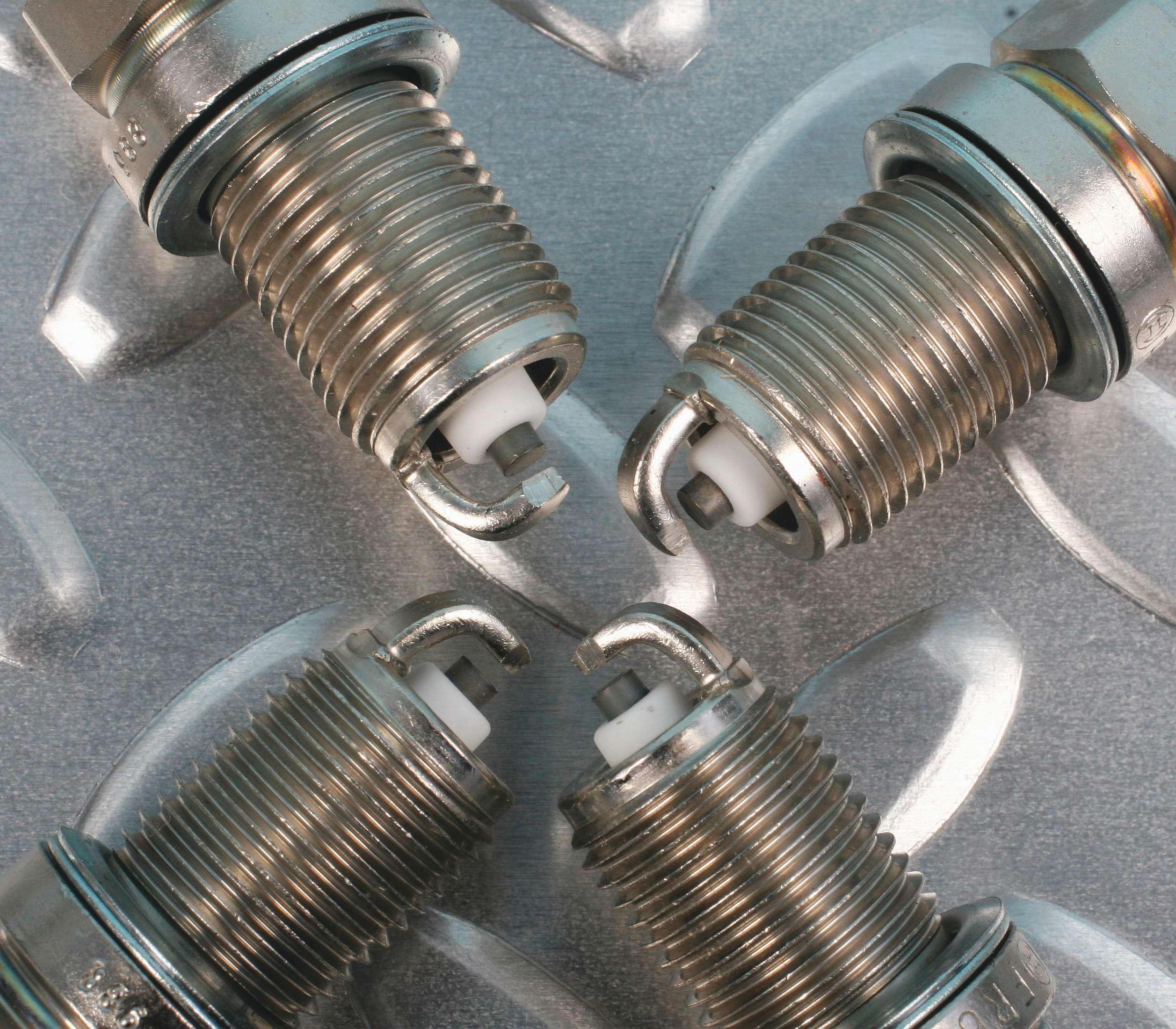
There are numerous ground electrode designs aimed at decreasing the possibility of misf ring while increasing the likelihood of producing a good spark with a large kernel to light off the air/fuel mixture. For instance, the groove design of some of Denso’s plugs effectively create a wider gap in the channel while providing a smaller gap for the initial spark to bridge.
NGK’s V-Power spark plugs have a grooved center electrode that helps achieve the same goal.
One-hundred-thousand-mile replacement intervals are now the norm. Prior to the platinum plug, it was common to replace spark plugs in as little as 20,000 miles.
Not only are extended change intervals attractive to the modern car owner who is often lax about maintenance, those intervals may save money and hassle.
As you know, with many vehicles, it is nearly impossible to reach one or more of the plugs due to engine design, layout or under hood space. Dropping the engine cradle to change one of the plugs is labor intensive.
Although most spark plugs will probably work f ne, even well beyond the 100,000 mile mark, the gradually eroding gaps can put a strain on the rest of the ignition system. That’s something worth explaining to your customers. And remember that short trip driving, worn mechanical parts, such as rings and valve guides, can lead to plug fouling and the need for replacement.
Spark plug of the future
What may become of the spark plug in the future? For one thing, it may get much smaller. Heads are becoming full of holes. Along with multiple valves, there is now direct injection. As displacement continues to shrink so does the space in the head for spark plugs so they may become as thin as pencils.
Another possible solution is lasers. They are already being employed on large stationary industrial engines.
Yet another possibility is plasma ignition. It is found on some race car engines and jet aircraft engines.
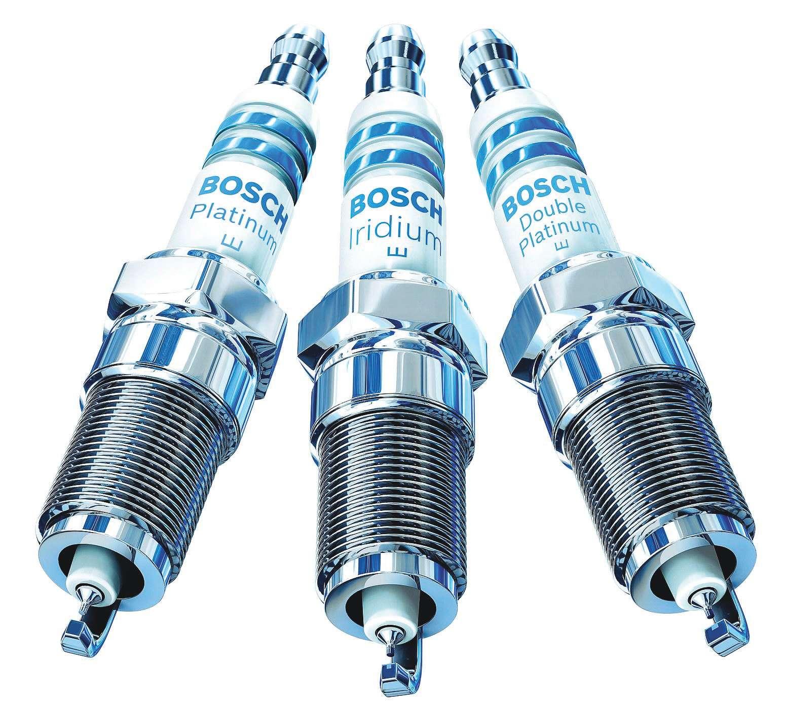
Bosch iridium spark plugs. Iridium is harder and more corrosion resistant than platinum.
Bosch reports that homogenous charged compression ignition (HCCI), which is similar to that used by diesel engines, is a technology being investigated.
Corona discharge is another technology on the near horizon. Champion Spark Plugs has as patent pending on a spark plug that creates long streams of ionization to replace the small spark created across a conventional gap.
Then again, ignition may be supplied by something completely new and ingenious like what happened over a century ago.
Spark plug replacement
Spark plug replacement is such a routine job, that it is often assigned to a rookie in the shop. But it does not hurt anyone to review the steps for proper plug replacement.
• Start with a cold or cool engine. This helps avoid thread damage, especially in aluminum heads. • Unless the plugs are protected from the environment such as COP plugs, used compressed air to blow any sand, dirt or debris from the spark plug wells. • Crack the plugs loose using a spark plug socket. If they f ght back, squirt a little penetrant into the well and allow it to soak in for several minutes. Ford Triton engines may need to soak as long as overnight. (See ASP May/June 2011.) • If the plugs did not come out smoothly,

Circle 122 on Reader Service Card
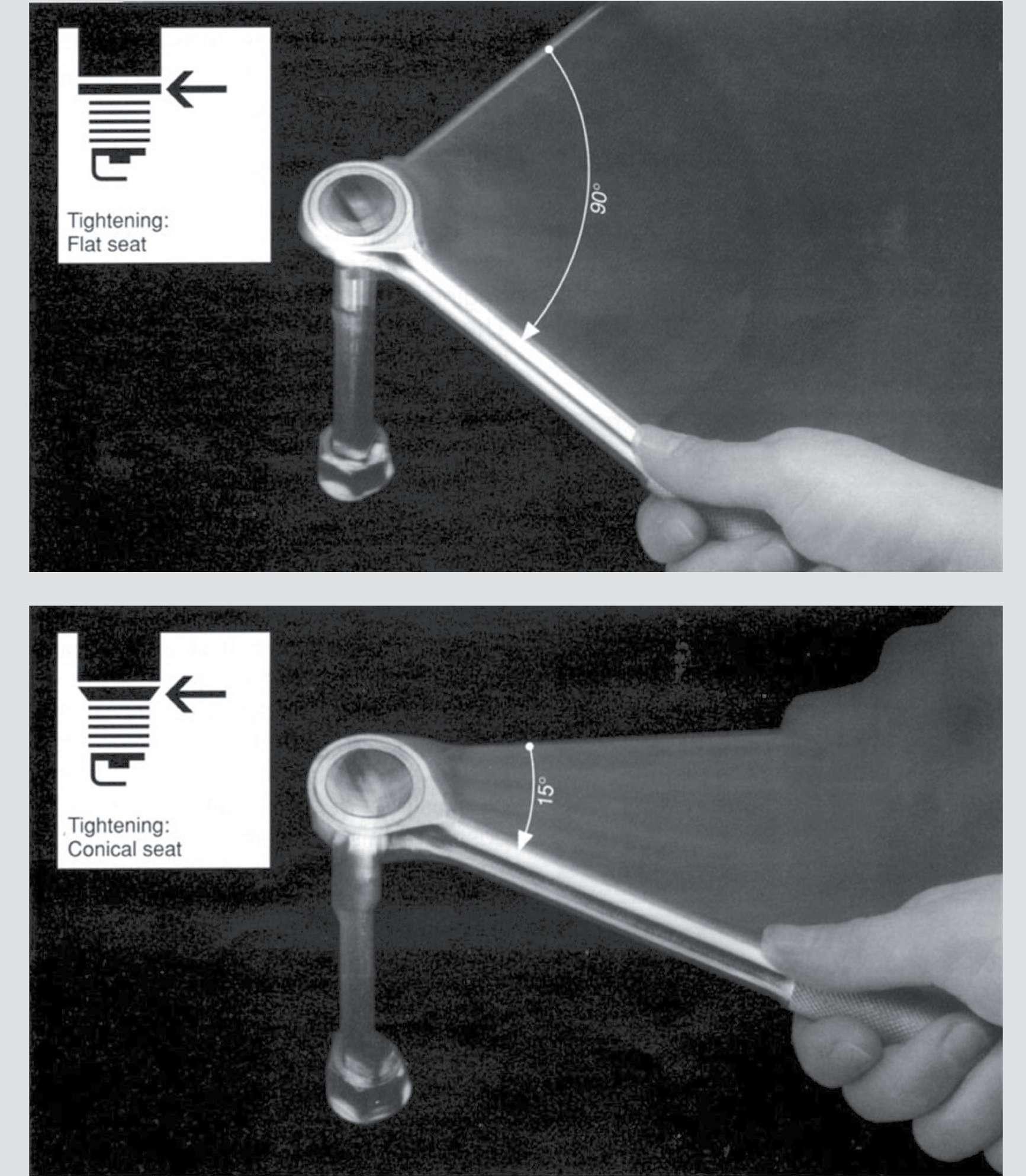
Here’s a tidbit of information for tightening spark plugs when the use of a torque wrench isn’t practical or preferred. Once seat contact is achieved, tighten a f at-seat style spark plug by 90-degrees and a conical-seat spark plug by 15 degrees.
you may want to chase the threads in the cylinder head (use a chaser tap to re-form the threads, not a cutting tap.) • Check the gap on new plugs. Most spark plugs come properly gapped from the factory, but it never hurts to verify. If you need to re-gap do not pry on the center electrode as it will likely snap off. • Do not use anti-seize compound even if
those old timers say you must. It can lead to fouling and over-tightening. Today’s plugs are treated to prevent seizure. If you insist, apply anti-seize very sparingly to only the top few threads to prevent it from getting on the electrodes and reduce torque by about 30%. • Install the new plugs by hand to avoid cross-threading. In deep, hard-to-reach
places, put a length of vacuum hose on the plug to extend your reach. • Use a torque wrench in order to properly tighten according to the engine manufacturer’s specs. Improperly torqued spark plugs can lead to costly damage. • If you refuse to use a torque wrench, give f at seat (gasketed) plugs a 90-degree turn after they make seat contact. Give conical-seat plugs a 15-degree turn. Do not use a half-inch drive ratchet.
Spark plug heat ranges
There is a common misconception about spark plug heat ranges, even among some technicians. The error is in thinking a hotter spark plug creates a hotter spark, hence it must be a better spark. Nope. Heat range refers to the plug’s ability to dissipate heat from the tip. Hotter plugs dissipate the heat slower which helps prevent deposits. Colder plugs dissipate the heat quicker to reduce the likelihood of knock. Here is how NGK explains the conditions and solutions:
Fuel type/quality
• Low quality and/or low octane fuel can cause knock which will elevate cylinder temperatures. The increased cylinder temperature will cause the temperature of the combustion chamber components (spark plug, valves, piston, etc.) to rise, and will lead to pre-ignition if the knock is uncontrolled. • When using an ethanol blend fuel with high ethanol content in high performance applications, a colder heat range may be necessary. The spark timing can be advanced further because ethanol blend fuel has a higher resistance to knock (higher octane). Due to the decreased knock, there will be less audible “warning” from knock before the spark plug overheats and pre-ignites. • Some types of fuel additives in lower quality fuels can cause spark plug deposits that can lead to misf res, pre-ignition, etc.
Ignition timing
• Advancing ignition timing by 10 degrees will cause the spark plug tip temperature
to increase by approximately 70 degrees to 100 degrees Celcius. • A colder heat range spark plug may be necessary if the ignition timing has been advanced to near the knock level. Higher cylinder temperatures near the knock level will bring the spark plug f ring end temperature closer to the pre-ignition range.
Compression ratio
• Signif cantly increasing the static/ dynamic compression ratio will increase cylinder pressures and the octane requirement of the engine. Knock may occur more easily. If the engine is operated near the knock level, a colder heat range spark plug may be necessary due to the resulting increased cylinder temperatures.
Forced induction (turbocharging, supercharging)
• A colder heat range spark plug may be necessary due to the increased cylinder temperature as boost pressure (manifold pressure) and subsequent cylinder pressure and temperature increase.
Ambient air temperature/humidity
• As the air temperature or humidity decreases, the air density increases, requiring a richer air-fuel mixture. If the air-fuel mixture is not properly richened, and the mixture is too lean, higher cylinder pressures/temperatures, knocking, and the subsequent increase in the spark plug tip temperatures can result. • As the air temperature or humidity increases, the air density decreases, requiring a leaner air-fuel mixture. If the air-fuel mixture is too rich, decreased performance and/or carbon fouling can result.
Barometric pressure/altitude
• Air (atmospheric) pressure and cylinder pressure decrease as altitude increases. As a result, spark plug tip temperature will also decrease. • Fouling can occur more easily if the air-fuel mixture is not adjusted to compensate for the altitude. Higher altitude = less air = less fuel. ●
Circle 124 on Reader Service Card
Noise/vibration/ harshness
Chasing the irritant gremlins
Part two of two By Mike Mavrigian
In part one of this article in our January/ February 2013 issue we covered various sources of vibrations and noises that may be described by your customers. We also covered radial force variation (RFV) and its causes and solutions. In this article, we will take a closer look at the types of vibration plus harshness complaints and solutions.
Vibration is a shaking or trembling that can be felt by the customer when an object/component moves back and forth or up and down consistently. Abnormal vibrations usually occur under certain vehicle operating conditions.
There are three types of vibrations:
1. Free vibration — a vibration that continues after the cause has been removed. For example, a tire hitting a pothole will continue to vibrate after the initial impact has passed. 2. Forced vibration — a vibration that only occurs as long as the force that initiated the vibration remains. For example, an unbalanced driveshaft only causes a vibration as long as it is rotating. Another example would be an unbalanced tire, which would stop vibrating when it stops rotating. Forced vibrations are the most common type dealt with in automotive applications. 3. Torsional vibration — vibration caused by a constant twisting force that is felt in the f oor and seats
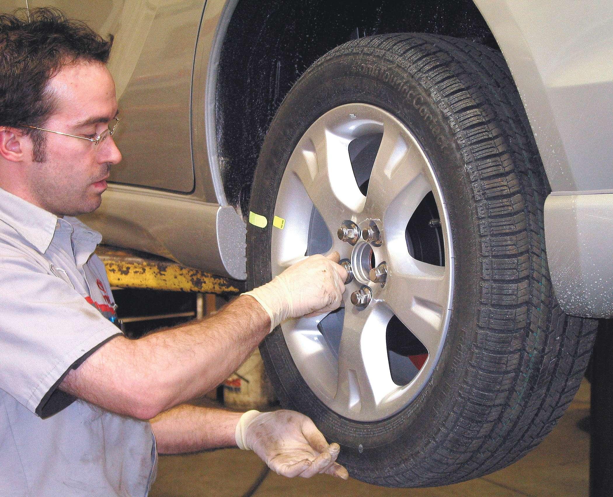
It may seem obvious, but the wheel must be properly centered on the hub. If the wheel is lug centric, the position of the wheel studs dictate centering. If hub centric, the center of the hub engages to the wheel’s center hole for proper wheel position. of the vehicle. This type of vibration is most noticeable during hard acceleration and is amplif ed by the application of torque.
Under normal circumstances, a rotating component will not produce a noticeable vibration. However, if the component has improper weight distribution (imbalance) or is rotating in an eccentric pattern (outof-round or bent), then a vibration may be produced. If the frequency and amplitude of the vibration can be measured, then those characteristics along with the vehicle speed and engine rpm at which the vibration occurs, can be matched with components that would likely cause the vibration at that particular speed. This procedure can help f nd the source quickly and accurately.
Vibrations are often noticed in a component far removed from where they are generated. This is called transfer path or telegraphing. For example, an out-ofbalance front tire and wheel assembly may result in a noticeable steering wheel shake.

In this case, we would call the wheel and tire assembly the origin (or originator), the steering linkage the conductor, and the steering wheel the reactor.
Damaged or worn engine and body mounts or a grounded exhaust hanger are components that could transmit (conduct) a normal engine vibration (originator) into the passenger compartment (reactor) as an NVH concern.
Harshness
Harshness is a concern that is related to the customer’s perception or expectation of a vehicle’s ability to absorb vibrations caused by road imperfections.
Harshness is usually the result of:
• Deterioration of vehicle components — such as worn or damaged suspension components that cannot move within their normal range of motion, or that have lost their isolating grommets or bearings. • Modif cation of original equipment — such as over-sized tires or heavy-duty springs and shocks. • Improper tire inf ation — over– or underinf ated tires can cause a harsh ride.
Advanced electronic listening devices, such as the ChassisEAR, can be used to quickly identify a noise and its location under the chassis while the vehicle is being road-tested.
These versatile devices can identify the noise and location of bad wheel bearings and various problems in the differential transmission, CV joints, brakes, leaf and coil springs, transfer case, pinion bearings or carrier bearings.
For example, the ChassisEAR has a sixposition input selection control switch with six microphone clamps that are attached to 16-foot leads. The leads are secured to the vehicle with clamps and Velcro ties.
The ChassisEAR provides instant comparisons between any of the six channels during the road test. The unit is equipped with headphones that block out surrounding noises. Road test with customer
Observe the following when preparing for the road test:
• Check the customer repair order before beginning the road test. It is important to know what specif c concern the customer has with the automobile. This prevents correcting the wrong concern, and increasing the cost of repair. • Do not be misled by the reported location of the noise or vibration. The cause may actually be some distance away. • Remember that the vibrating component (originator) may only generate a small vibration. This small vibration may in turn cause a larger vibration or noise with a component (reactor), due to contact with other components (conductor). • Conduct the road test on a quiet street where safely duplicating the noise or vibration is possible. The ideal testing route is an open, low-traff c area. It must be possible to operate the vehicle at the speed in which the condition occurs. • If possible, lower the radio antenna in order to minimize turbulence. Inspect the vehicle for add-on items that may be creating a noise. Turn off the radio and blower for the heater and air conditioner.
Slow acceleration test
The f rst vehicle test used in determining an NVH concern is the slow acceleration test. This test is used to identify the noise or vibration if a road test with the customer is not possible. The steps of the slow acceleration test are:
• Slowly accelerate the vehicle to the speed where the problem occurs. Note the vehicle speed and the engine RPM. If possible, determine the frequency of the vibration. • Attempt to identify the location of the concern (front or rear, and right or left) on the vehicle. • Attempt to identify the noise or vibration.
Heavy acceleration test
This test is done to determine if a concern is torque related.

• Accelerate hard from 0-40 mph. • Decelerate in a lower gear at the reported speed. • If the concern is duplicated during this test, it is torque related.
Neutral coast down speed test
The next step when performing the road test is the Neutral coast down speed test. This test determines if an NVH concern is vehicle speed-related. The steps of the Neutral coast down speed test are:
• Drive the vehicle at a speed higher than where the noise or vibration was obvious in the slow acceleration test. • Place the vehicle in Neutral and coast down through the speed where the concern occurs. • If the noise or vibration exists, the concern is vehicle speed-related. This eliminates the engine and torque converter. • If the NVH concern did not occur during the Neutral coast down speed test, perform a downshift speed test to conf rm the concern as engine speed-related.
Downshift speed test
This vehicle test helps to conf rm the NVH concern as engine speed-related.
The steps of the downshift speed test are:
• Stop the vehicle and place the transmission in a lower gear. • Drive the vehicle at the engine RPM where the noise or vibration occurs. • If the noise or vibration exists, the concern is engine speed-related. This eliminates tires, wheels, brakes, and suspension components. • If necessary, repeat the test using other gears and Neutral to conf rm the results.
Steering input test
This test determines how wheel bearings and other suspension components contribute to a vehicle speed-related condition. The steps of the steering input test are:

NVH concern exists, while making sweeping turns in both directions. • If the concern goes away or gets worse, wheel bearings, hubs, U-joints (contained in the axles of 4WD applications), and tire tread wear can be the components causing the concern.
Road test over bumps
The road test over bumps is used to help isolate a noise that occurs when going over a rough road or a bump. By driving the vehicle across a bump or dip diagonally, one wheel at a time will hit the bump or dip. This will isolate the noise to one quadrant of the vehicle.
• To determine if the noise is coming from the front or the back, drive only the front or rear wheels over a bump. • To determine if the noise is on the left or the right, drive one wheel over a bump.
Engine run-up tests
Engine run-up tests are performed on a hoist with an accurate tachometer connected to the engine. Even if the vehicle has a tachometer, it is a good idea to use one that has clearly def ned increments of less than 50 rpm so that an exact reading of engine speed can be recorded. Engine speed will be an important factor in arriving at a f nal conclusion.
Perform the Neutral run-up and engine loaded tests if the NVH concern is engine speed-related.
Neutral run-up test
Use the Neutral run-up test as a follow-up to the downshift test or when the NVH concern occurs at idle. The steps of the Neutral run-up test are:
• Increase the engine rpm while in Park on front wheel drive vehicles, or Neutral on rear wheel drive vehicles. • Make note of the rpm and frequency of the NVH concern.
Engine loaded test
The second in-shop test is the engine loaded test. This test may help reproduce engine speed-related concerns not evident with the Neutral run-up or Neutral coast down tests.
The engine loaded test also identif es noise and vibration sensitive to engine load or torque. These NVH concerns often appear during heavy acceleration or when climbing a hill.
WARNING: Block the front and back wheels, or injury to personnel may result. Do not exceed f ve seconds when performing the engine loaded test or damage to the transaxle may result.
The steps of the engine loaded test are: • Block the front and back wheels. • Apply the parking and service brakes. • Put the transmission in Drive and increase the engine rpm to where the NVH concern appears. Make note of the rpm and frequency of the NVH concern. • Be sure to perform the test in Drive and then in Reverse. If the noise or vibration occurs, check engine and transaxle mounts. • If the concern is def nitely engine speedrelated, perform the engine accessory test to narrow down the trouble source.
Engine accessory test
Noises from specif c accessories can usually be identif ed with electronic listening devices, such as the EngineEAR.
CAUTION: Block the front and back wheels, or injury to personnel may result. Limit running time with belts removed or overheating may result.
The steps of the engine accessory test are: • Remove the accessory drive belts. • Increase engine rpm to where the NVH concern is obvious. • If the vibration occurs, the belts and accessories are not the source. • If the belts and accessories are the source of the NVH concern, continue to add or remove specif c accessory belts to locate the concern.
NOTE: Some of the information provided here was gleaned from Toyota and Ford training materials. ●


